EP0721541B1 - Verfahren und vorrichtung zur darstellung des betriebszustandes einer turbine während eines anfahrvorgangs - Google Patents
Verfahren und vorrichtung zur darstellung des betriebszustandes einer turbine während eines anfahrvorgangs Download PDFInfo
- Publication number
- EP0721541B1 EP0721541B1 EP94926772A EP94926772A EP0721541B1 EP 0721541 B1 EP0721541 B1 EP 0721541B1 EP 94926772 A EP94926772 A EP 94926772A EP 94926772 A EP94926772 A EP 94926772A EP 0721541 B1 EP0721541 B1 EP 0721541B1
- Authority
- EP
- European Patent Office
- Prior art keywords
- turbine
- starting
- speed
- time
- determined
- Prior art date
- Legal status (The legal status is an assumption and is not a legal conclusion. Google has not performed a legal analysis and makes no representation as to the accuracy of the status listed.)
- Expired - Lifetime
Links
- 238000000034 method Methods 0.000 title claims abstract description 32
- 238000003384 imaging method Methods 0.000 title abstract 3
- 230000002123 temporal effect Effects 0.000 description 3
- 238000005259 measurement Methods 0.000 description 2
- 230000001419 dependent effect Effects 0.000 description 1
- 238000010586 diagram Methods 0.000 description 1
- 238000012544 monitoring process Methods 0.000 description 1
- 230000036962 time dependent Effects 0.000 description 1
Images
Classifications
-
- F—MECHANICAL ENGINEERING; LIGHTING; HEATING; WEAPONS; BLASTING
- F01—MACHINES OR ENGINES IN GENERAL; ENGINE PLANTS IN GENERAL; STEAM ENGINES
- F01D—NON-POSITIVE DISPLACEMENT MACHINES OR ENGINES, e.g. STEAM TURBINES
- F01D19/00—Starting of machines or engines; Regulating, controlling, or safety means in connection therewith
Definitions
- the invention relates to a method of representation the operating state of a turbine during a start-up process according to the preamble of claim 1. It relates further on a device for performing the method according to the preamble of claim 4.
- the starting process of a turbine e.g. a steam turbine, from Standstill up to idle or operating speed continues usually together from different speed increases and waiting times.
- the temporal increase in speed depends on this until the operating speed is reached in particular from turbine-specific parameters and from thermal Condition of the turbine.
- the invention is therefore based on the object of a method specify with which a suitable representation of the operating state the turbine is possible during the start-up process. With a suitable device, this should be done with simple means can be achieved.
- the reference curve represents the functional dependency the temporal change in the turbine speed from the turbine-specific parameters and those derived from measured values operational parameters.
- Each starting characteristic is expediently by a value for the downtime of the turbine and by a value for marked the turbine temperature. Therefore, advantageously the turbine temperature as operationally relevant parameters and the downtime of the turbine is detected.
- the downtime is derived from the turbine speed, by standing still or approaching Standstill of the turbine past time is recorded.
- the time shown is expedient History of the turbine speed saved at the same time.
- the storage process is between a start signal and a Stop signal which is reached when an idling or operating speed is reached the turbine is released.
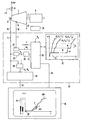
- An embodiment of the invention is based on a Drawing explained in more detail. It shows schematically a device to illustrate the starting process of a turbine.
- the figure shows the turbine 2 on a shaft 4, over the one Unit 6, e.g. a generator or an air compressor becomes.
- the turbine 2 is turned on via a valve 8
- Working medium AM supplied supplied, the whole or in the turbine is partially relaxed and drives the turbine 2.
- the working medium AM flows out via an outflow line 10 the turbine 2.
- the turbine 2 is a steam or gas turbine.
- a first sensor 12 for measuring the turbine speed n and a second sensor 14 for measuring the turbine temperature T provided.
- One from each of the sensors 12 and 14 Signal line 16 or 18 from the turbine speed n and signals corresponding to the turbine temperature T are dashed shown device 20 for processing measured values and processing.
- the temperature T is expediently measured on the turbine housing.
- the device 20 comprises a converter 22 connected to the signal line 16 and a converter 24 connected to the signal line 18.
- a signal k s characteristic of the rotational state of the turbine 2 is formed in the converter 22 by limit value monitoring of the turbine speed n. This indicates whether the turbine 2 is at a standstill or approximately at a standstill.
- the signal k s is forwarded to a time module 26 connected downstream of the converter 22. When the signal k s arrives, the time module 26 is started. This forms a time factor k z from the signal k s , which informs a first arithmetic unit 28 of the period of time that has passed since the standstill signal k s arrived.
- the position of a quick-closing valve of the actuator 8 is additionally queried in the form of a feedback signal s. If the actuator 8 is closed, there is a corresponding feedback s to the arithmetic unit 28. If the converter 22 detects that the turbine speed n falls below the limit value and generates a signal k s , the time factor k z is used to indicate the start of the standstill period where the turbine speed n is zero.
- a temperature factor k T which describes the thermal state of the turbine 2, is formed in the converter 24 from a measurement of the temperature T of the turbine 2, for example by means of a characteristic curve.
- the temperature factor k T is forwarded to the computing unit 28.
- an adjustable process factor k p which is derived from the process criteria, is fed to the computing unit 28 via an operating element 30.
- the arithmetic unit 28 uses the factors k T , k z and k p and turbine-specific parameters stored in a memory 32 to determine a reference curve RV for a starting process of the turbine 2.
- the memory 32 contains a number of starting characteristics A n , each of which Starting characteristic curve A n is provided with an identifier for a downtime t n and a turbine temperature T n .
- Starting characteristic curve A n is provided with an identifier for a downtime t n and a turbine temperature T n .
- Some typical starting characteristic curves A n with their time-dependent setpoint or reference speed curve are illustrated in a diagram 33.
- Each start-up characteristic curve A n is assigned turbine-specific parameters, such as, for example, speed increase gradients m, waiting times w and a critical speed range b, which must be passed through particularly quickly.
- the starting characteristic curve A n with the longer waiting times w and / or flatter speed increase gradient m is determined as the reference curve RV .
- the process factor k p also takes into account the case where the unit 6 driven by the turbine 2 requires longer waiting times w or flatter speed increase gradients m compared to the turbine 2. In this case too, a starting characteristic curve A n-1, which takes into account the turbine 2 alone, the next flatter starting characteristic curve A n is determined. This avoids unnecessary loads on the turbine 2 and / or the unit 6.
- the reference curve RV determined by means of the factors k T , k z and k p is passed on to a display device 36 via a signal line 34 and is shown there in a coordinate field 38.
- the abscissa forms the time axis labeled t and the ordinate the speed axis labeled n.
- a start signal k a is generated in a converter 39 by means of the signal k s and the speed n. This is forwarded to a second computing unit 40.
- a signal from a turbine controller can also be used to form the start signal k a .
- the instantaneous actual value of the speed n is forwarded by the computing unit 40 to the display device 36 via a signal line 42.
- the current time course AV up to the current actual value I is shown there.
- the current actual value I and the setpoint S of the reference curve RV that is present at the same time t are shown in a bar chart 44. If a limit value query of the speed n in the converter 38 indicates that an idling or operating speed of the turbine 2 has been reached, the converter 38 forwards a stop signal k b to the computing unit 40; the saving process is then ended.
- the memory content of the computing units is via the display device 36 28 and 40 in curve form RV, AV available. Consequently any start of the turbine 2 by displaying the reference course RV and the current one temporal course AV are retrieved, so that both during a current starting process as well as a later one Control a direct comparison between the actual Speed curve AV and the reference curve RV during the starting process of the turbine 2 is possible.
Landscapes
- Engineering & Computer Science (AREA)
- Mechanical Engineering (AREA)
- General Engineering & Computer Science (AREA)
- Control Of Turbines (AREA)
- Control Of Eletrric Generators (AREA)
Applications Claiming Priority (3)
| Application Number | Priority Date | Filing Date | Title |
|---|---|---|---|
| DE4332078A DE4332078A1 (de) | 1993-09-21 | 1993-09-21 | Verfahren und Vorrichtung zur Darstellung des Betriebszustandes einer Turbine während eines Anfahrvorgangs |
| DE4332078 | 1993-09-21 | ||
| PCT/DE1994/001039 WO1995008700A1 (de) | 1993-09-21 | 1994-09-09 | Verfahren und vorrichtung zur darstellung des betriebszustandes einer turbine während eines anfahrvorgangs |
Publications (2)
| Publication Number | Publication Date |
|---|---|
| EP0721541A1 EP0721541A1 (de) | 1996-07-17 |
| EP0721541B1 true EP0721541B1 (de) | 1998-04-22 |
Family
ID=6498220
Family Applications (1)
| Application Number | Title | Priority Date | Filing Date |
|---|---|---|---|
| EP94926772A Expired - Lifetime EP0721541B1 (de) | 1993-09-21 | 1994-09-09 | Verfahren und vorrichtung zur darstellung des betriebszustandes einer turbine während eines anfahrvorgangs |
Country Status (12)
| Country | Link |
|---|---|
| US (1) | US5807069A (OSRAM) |
| EP (1) | EP0721541B1 (OSRAM) |
| JP (1) | JP3784406B2 (OSRAM) |
| KR (1) | KR100363072B1 (OSRAM) |
| CN (1) | CN1057815C (OSRAM) |
| AT (1) | ATE165423T1 (OSRAM) |
| AU (1) | AU679563B2 (OSRAM) |
| CA (1) | CA2172254C (OSRAM) |
| DE (2) | DE4332078A1 (OSRAM) |
| ES (1) | ES2115972T3 (OSRAM) |
| TW (1) | TW264520B (OSRAM) |
| WO (1) | WO1995008700A1 (OSRAM) |
Families Citing this family (6)
| Publication number | Priority date | Publication date | Assignee | Title |
|---|---|---|---|---|
| KR100815706B1 (ko) * | 2001-12-21 | 2008-03-20 | 주식회사 포스코 | 기력발전 터빈의 열팽창에 따른 승속 제어장치 |
| KR20040051794A (ko) * | 2002-12-13 | 2004-06-19 | 주식회사 포스코 | 터빈 기동 시 터빈 회전 속도 제어 방법 |
| DE102004015126A1 (de) * | 2004-03-27 | 2005-10-13 | Robert Bosch Gmbh | Verfahren und Vorrichtung zur Übertragung einer Kennung für den Typ eines Generators an ein Steuergerät eines Kraftfahrzeugs |
| DE102008021102A1 (de) * | 2008-04-28 | 2009-10-29 | Siemens Aktiengesellschaft | Wirkungsgradüberwachung eines Verdichters |
| US8839664B2 (en) | 2012-04-06 | 2014-09-23 | Siemens Energy, Inc. | Detection and classification of failures of power generating equipment during transient conditions |
| CN103364200B (zh) * | 2013-07-03 | 2015-12-02 | 哈尔滨工程大学 | 一种燃气轮机启动过程状态评估方法 |
Family Cites Families (10)
| Publication number | Priority date | Publication date | Assignee | Title |
|---|---|---|---|---|
| DE269032C (OSRAM) * | ||||
| DE1576952A1 (de) * | 1967-10-05 | 1970-07-02 | Escher Wyss Gmbh | Schaltungsanordnung und Fahrleitgeraet zum Anfahren von Dampfturbinen |
| DE2206780A1 (de) * | 1972-02-12 | 1973-08-16 | Siemens Ag | Anfahreinrichtung fuer einen an eine turbine angekuppelten generator |
| US4181840A (en) * | 1975-02-13 | 1980-01-01 | Westinghouse Electric Corp. | Anticipative turbine control |
| DD146359B3 (de) * | 1979-09-26 | 1992-07-30 | Veag Vereinigte Energiewerke Ag | Verfahren zur bauteilueberwachung und prozesssteuerung in dampferzeugeranlagen |
| DD206440A1 (de) * | 1981-07-17 | 1984-01-25 | Orgreb Inst Fuer Kraftweke | Verfahren zur darstellung und bewertung von prozessfuehrungsbedingungen |
| US4644270A (en) * | 1982-08-31 | 1987-02-17 | Westinghouse Electric Corp. | Apparatus for monitoring housed turbine blading to obtain blading-to-housing distance |
| DD269032A1 (de) * | 1985-12-20 | 1989-06-14 | Zittau Ing Hochschule | Verfahren zur bestimmung zulaessiger betriebsbereiche von drehstromasynchronmotorantrieben |
| EP0275192A3 (en) * | 1987-01-16 | 1989-07-19 | General Electric Company | Reconfigurable integrated controls and displays for a turbomachine |
| DE4120602C2 (de) * | 1991-06-21 | 1995-02-02 | Porsche Ag | Verfahren zur selbsttätigen Steuerung einer drehzahlwandelnden Anfahreinrichtung eines Kraftfahrzeugs |
-
1993
- 1993-09-21 DE DE4332078A patent/DE4332078A1/de not_active Withdrawn
-
1994
- 1994-09-09 CN CN94193471A patent/CN1057815C/zh not_active Expired - Fee Related
- 1994-09-09 WO PCT/DE1994/001039 patent/WO1995008700A1/de not_active Ceased
- 1994-09-09 JP JP50947995A patent/JP3784406B2/ja not_active Expired - Fee Related
- 1994-09-09 CA CA002172254A patent/CA2172254C/en not_active Expired - Fee Related
- 1994-09-09 AU AU76507/94A patent/AU679563B2/en not_active Ceased
- 1994-09-09 DE DE59405807T patent/DE59405807D1/de not_active Expired - Lifetime
- 1994-09-09 EP EP94926772A patent/EP0721541B1/de not_active Expired - Lifetime
- 1994-09-09 ES ES94926772T patent/ES2115972T3/es not_active Expired - Lifetime
- 1994-09-09 KR KR1019960701408A patent/KR100363072B1/ko not_active Expired - Fee Related
- 1994-09-09 AT AT94926772T patent/ATE165423T1/de active
- 1994-09-15 TW TW083108534A patent/TW264520B/zh not_active IP Right Cessation
-
1996
- 1996-03-21 US US08/619,088 patent/US5807069A/en not_active Expired - Lifetime
Also Published As
| Publication number | Publication date |
|---|---|
| ES2115972T3 (es) | 1998-07-01 |
| AU7650794A (en) | 1995-04-10 |
| CA2172254A1 (en) | 1995-03-30 |
| TW264520B (OSRAM) | 1995-12-01 |
| ATE165423T1 (de) | 1998-05-15 |
| CN1057815C (zh) | 2000-10-25 |
| JPH09506945A (ja) | 1997-07-08 |
| DE59405807D1 (de) | 1998-05-28 |
| EP0721541A1 (de) | 1996-07-17 |
| KR960705124A (ko) | 1996-10-09 |
| JP3784406B2 (ja) | 2006-06-14 |
| CA2172254C (en) | 2005-09-06 |
| AU679563B2 (en) | 1997-07-03 |
| CN1131450A (zh) | 1996-09-18 |
| DE4332078A1 (de) | 1995-03-30 |
| US5807069A (en) | 1998-09-15 |
| KR100363072B1 (ko) | 2003-03-10 |
| WO1995008700A1 (de) | 1995-03-30 |
Similar Documents
| Publication | Publication Date | Title |
|---|---|---|
| DE69526148T2 (de) | Ladeeinrichtung für ein Fahrzeug | |
| DE3443276C2 (de) | Einrichtung und Verfahren zum Bestimmen der verbleibenden unklaren Lebensdauer eines Motors | |
| DE69610723T2 (de) | Flurförderfahrzeug mit interner Temperaturüberwachung | |
| EP1240703B1 (de) | Verfahren zur überwachung des radialen spalts zwischen rotor und stator elektrischer generatoren und vorrichtung zu dessen durchführung | |
| DE102004012222B4 (de) | Umgebungslufttemperaturvorhersage | |
| DE10037968B4 (de) | Elektrischer Antrieb mit Motoridentifizierung und Verfahren zur Motoridentifizierung | |
| DE202007019440U1 (de) | Vorbeugendes Instandhaltungssystem | |
| EP0713580B1 (de) | Verfahren und vorrichtung zur temperaturüberwachung eines elektrischen generators | |
| EP1490960A1 (de) | Verfahren und vorrichtung zur ermittlung der rotortemperatur bei einer pm-synchronmaschine | |
| EP3454071A1 (de) | Verfahren zur überwachung der funktion eines kühlsystems einer magnetresonanzeinrichtung, magnetresonanzeinrichtung, computerprogramm und elektronisch lesbarer datenträger | |
| DE112020005865B4 (de) | Verarbeitungseinrichtung und Verfahren zur Bestimmung eines Modells zur Berechnung von Wicklungstemperaturen | |
| DE102018207004A1 (de) | System zum Kühlen einer Elektromaschine | |
| DE69619318T2 (de) | Verfahren zur Detektion einer Fehlfunktion in einer Kühlerlüfteranlage | |
| DE102005045249B4 (de) | Elektronische Steuereinheit für Fahrzeuge | |
| EP0721541B1 (de) | Verfahren und vorrichtung zur darstellung des betriebszustandes einer turbine während eines anfahrvorgangs | |
| DE102014005706A1 (de) | Verfahren und Vorrichtung zum Betreiben eines Elektromotors | |
| DE102004055073A1 (de) | Überlastschutz für Gleichstrommotoren | |
| DE102019217814A1 (de) | Gasturbine und verfahren zum steuern eines zapfluftvolumens für die gasturbine | |
| DE102009053088B4 (de) | Vorrichtung und Verfahren zur Solenoidstromregelung mit direkter Vorwärtsprognose und iterativer Rückwärtsstatusschätzung | |
| DE102015207710B4 (de) | Verfahren zur Erhöhung der Genauigkeit einer sensorlosen Druckerfassung | |
| DE102015210226A1 (de) | Verfahren und Vorrichtung zur Erhöhung der Leistung eines Verbrennungsmotors durch Nutzung eines Turboladerdrehzahlmodells und eines Turboladerdrehzahlsensors | |
| DE102009045147A1 (de) | Verfahren zum Schutz eines Kraftfahrzeuggenerators vor einer Überhitzung | |
| DE102005023276A1 (de) | Verfahren zur Bestimmung der Initialwerte für ein Temperaturschätzverfahren von Komponenten eines Kraftfahrzeugs | |
| DE102019005013A1 (de) | Motorsteuerung und motorsteuerverfahren | |
| EP1082806B1 (de) | Verfahren und schaltungsanordnung zur stromerfassung elektronisch kommutierter elektromotoren |
Legal Events
| Date | Code | Title | Description |
|---|---|---|---|
| PUAI | Public reference made under article 153(3) epc to a published international application that has entered the european phase |
Free format text: ORIGINAL CODE: 0009012 |
|
| 17P | Request for examination filed |
Effective date: 19960207 |
|
| AK | Designated contracting states |
Kind code of ref document: A1 Designated state(s): AT CH DE ES FR GB IT LI NL SE |
|
| GRAG | Despatch of communication of intention to grant |
Free format text: ORIGINAL CODE: EPIDOS AGRA |
|
| GRAG | Despatch of communication of intention to grant |
Free format text: ORIGINAL CODE: EPIDOS AGRA |
|
| GRAH | Despatch of communication of intention to grant a patent |
Free format text: ORIGINAL CODE: EPIDOS IGRA |
|
| 17Q | First examination report despatched |
Effective date: 19970930 |
|
| GRAH | Despatch of communication of intention to grant a patent |
Free format text: ORIGINAL CODE: EPIDOS IGRA |
|
| GRAA | (expected) grant |
Free format text: ORIGINAL CODE: 0009210 |
|
| AK | Designated contracting states |
Kind code of ref document: B1 Designated state(s): AT CH DE ES FR GB IT LI NL SE |
|
| REF | Corresponds to: |
Ref document number: 165423 Country of ref document: AT Date of ref document: 19980515 Kind code of ref document: T |
|
| REG | Reference to a national code |
Ref country code: CH Ref legal event code: NV Representative=s name: SIEMENS SCHWEIZ AG Ref country code: CH Ref legal event code: EP |
|
| REF | Corresponds to: |
Ref document number: 59405807 Country of ref document: DE Date of ref document: 19980528 |
|
| ET | Fr: translation filed | ||
| REG | Reference to a national code |
Ref country code: ES Ref legal event code: FG2A Ref document number: 2115972 Country of ref document: ES Kind code of ref document: T3 |
|
| ITF | It: translation for a ep patent filed | ||
| GBT | Gb: translation of ep patent filed (gb section 77(6)(a)/1977) |
Effective date: 19980623 |
|
| PLBE | No opposition filed within time limit |
Free format text: ORIGINAL CODE: 0009261 |
|
| STAA | Information on the status of an ep patent application or granted ep patent |
Free format text: STATUS: NO OPPOSITION FILED WITHIN TIME LIMIT |
|
| 26N | No opposition filed | ||
| PGFP | Annual fee paid to national office [announced via postgrant information from national office to epo] |
Ref country code: ES Payment date: 19990921 Year of fee payment: 6 |
|
| PG25 | Lapsed in a contracting state [announced via postgrant information from national office to epo] |
Ref country code: ES Free format text: LAPSE BECAUSE OF NON-PAYMENT OF DUE FEES Effective date: 20000910 |
|
| REG | Reference to a national code |
Ref country code: GB Ref legal event code: IF02 |
|
| REG | Reference to a national code |
Ref country code: ES Ref legal event code: FD2A Effective date: 20011011 |
|
| REG | Reference to a national code |
Ref country code: CH Ref legal event code: PCAR Free format text: SIEMENS SCHWEIZ AG;INTELLECTUAL PROPERTY FREILAGERSTRASSE 40;8047 ZUERICH (CH) |
|
| PGFP | Annual fee paid to national office [announced via postgrant information from national office to epo] |
Ref country code: GB Payment date: 20120917 Year of fee payment: 19 Ref country code: SE Payment date: 20120911 Year of fee payment: 19 |
|
| PGFP | Annual fee paid to national office [announced via postgrant information from national office to epo] |
Ref country code: FR Payment date: 20121002 Year of fee payment: 19 Ref country code: IT Payment date: 20120927 Year of fee payment: 19 |
|
| PGFP | Annual fee paid to national office [announced via postgrant information from national office to epo] |
Ref country code: CH Payment date: 20121210 Year of fee payment: 19 Ref country code: DE Payment date: 20121119 Year of fee payment: 19 |
|
| PGFP | Annual fee paid to national office [announced via postgrant information from national office to epo] |
Ref country code: NL Payment date: 20120911 Year of fee payment: 19 Ref country code: AT Payment date: 20120810 Year of fee payment: 19 |
|
| REG | Reference to a national code |
Ref country code: NL Ref legal event code: V1 Effective date: 20140401 |
|
| REG | Reference to a national code |
Ref country code: SE Ref legal event code: EUG |
|
| PG25 | Lapsed in a contracting state [announced via postgrant information from national office to epo] |
Ref country code: SE Free format text: LAPSE BECAUSE OF NON-PAYMENT OF DUE FEES Effective date: 20130910 |
|
| REG | Reference to a national code |
Ref country code: CH Ref legal event code: PL |
|
| REG | Reference to a national code |
Ref country code: AT Ref legal event code: MM01 Ref document number: 165423 Country of ref document: AT Kind code of ref document: T Effective date: 20130909 |
|
| GBPC | Gb: european patent ceased through non-payment of renewal fee |
Effective date: 20130909 |
|
| REG | Reference to a national code |
Ref country code: DE Ref legal event code: R119 Ref document number: 59405807 Country of ref document: DE Effective date: 20140401 |
|
| REG | Reference to a national code |
Ref country code: FR Ref legal event code: ST Effective date: 20140530 |
|
| PG25 | Lapsed in a contracting state [announced via postgrant information from national office to epo] |
Ref country code: GB Free format text: LAPSE BECAUSE OF NON-PAYMENT OF DUE FEES Effective date: 20130909 Ref country code: CH Free format text: LAPSE BECAUSE OF NON-PAYMENT OF DUE FEES Effective date: 20130930 Ref country code: LI Free format text: LAPSE BECAUSE OF NON-PAYMENT OF DUE FEES Effective date: 20130930 |
|
| PG25 | Lapsed in a contracting state [announced via postgrant information from national office to epo] |
Ref country code: FR Free format text: LAPSE BECAUSE OF NON-PAYMENT OF DUE FEES Effective date: 20130930 Ref country code: AT Free format text: LAPSE BECAUSE OF NON-PAYMENT OF DUE FEES Effective date: 20130909 Ref country code: NL Free format text: LAPSE BECAUSE OF NON-PAYMENT OF DUE FEES Effective date: 20140401 Ref country code: IT Free format text: LAPSE BECAUSE OF NON-PAYMENT OF DUE FEES Effective date: 20130909 Ref country code: DE Free format text: LAPSE BECAUSE OF NON-PAYMENT OF DUE FEES Effective date: 20140401 |