EP0721134A2 - Frame for spectacles with improved hinge for the temples - Google Patents
Frame for spectacles with improved hinge for the temples Download PDFInfo
- Publication number
- EP0721134A2 EP0721134A2 EP96200225A EP96200225A EP0721134A2 EP 0721134 A2 EP0721134 A2 EP 0721134A2 EP 96200225 A EP96200225 A EP 96200225A EP 96200225 A EP96200225 A EP 96200225A EP 0721134 A2 EP0721134 A2 EP 0721134A2
- Authority
- EP
- European Patent Office
- Prior art keywords
- arm
- frame
- eyelets
- spectacles
- connecting element
- Prior art date
- Legal status (The legal status is an assumption and is not a legal conclusion. Google has not performed a legal analysis and makes no representation as to the accuracy of the status listed.)
- Granted
Links
Images


Classifications
-
- G—PHYSICS
- G02—OPTICS
- G02C—SPECTACLES; SUNGLASSES OR GOGGLES INSOFAR AS THEY HAVE THE SAME FEATURES AS SPECTACLES; CONTACT LENSES
- G02C5/00—Constructions of non-optical parts
- G02C5/008—Spectacles frames characterized by their material, material structure and material properties
-
- G—PHYSICS
- G02—OPTICS
- G02C—SPECTACLES; SUNGLASSES OR GOGGLES INSOFAR AS THEY HAVE THE SAME FEATURES AS SPECTACLES; CONTACT LENSES
- G02C1/00—Assemblies of lenses with bridges or browbars
- G02C1/02—Bridge or browbar secured to lenses without the use of rims
-
- G—PHYSICS
- G02—OPTICS
- G02C—SPECTACLES; SUNGLASSES OR GOGGLES INSOFAR AS THEY HAVE THE SAME FEATURES AS SPECTACLES; CONTACT LENSES
- G02C5/00—Constructions of non-optical parts
- G02C5/22—Hinges
-
- G—PHYSICS
- G02—OPTICS
- G02C—SPECTACLES; SUNGLASSES OR GOGGLES INSOFAR AS THEY HAVE THE SAME FEATURES AS SPECTACLES; CONTACT LENSES
- G02C2200/00—Generic mechanical aspects applicable to one or more of the groups G02C1/00 - G02C5/00 and G02C9/00 - G02C13/00 and their subgroups
- G02C2200/10—Frame or frame portions made from wire
Definitions
- the invention relates to a spectacle frame.
- the invention relates to an improvement to a frame comprising: a pair of arms or temples; for each arm, an element for connection to the respective lens and a hinge between each arm and the relevant connecting element.
- Frames of this type are described, for example, in US-A-718,363.
- the arms are each formed by a metal wire which, in the end portion adjacent to the lens, forms a helical spring portion constituting a resilient articulation, and a clip for anchoring to the lens.
- Each arm is linked to the respective lens just by the fact of the resilient force exerted by the clip, and this does not ensure a reliable connection between arm and lens.
- EP-B-0 256 098 discloses a frame for spectacles having connecting elements and relevant arms made by separate portions of wire. Each arm and the relevant connecting element are mutually articulated by a hinge formed by a wire portion making up the pivot and by a helically wound end portion surrounding the pivot and formed by the arm. This arrangement is expensive and the hinge difficult to produce.
- the subject of the present invention is constituted by a frame which overcomes the disadvantages of the conventional frames.
- a first subject of the present invention is the construction of a frame of the initially mentioned type, in which the arms and possibly the intermediate bridge can be linked to the lenses in a secure and reliable manner, without the risk of a relative movement with respect to the lenses and without risks of breakage of said lenses.
- a further subject of the present invention is a frame which is of low cost and which is easy to assemble.
- Figs. 1 to 9 show all the elements of a first embodiment of the frame according to the invention.
- Reference numeral 1 generally indicates, in Fig. 1, a pair of spectacles having two lenses L which are self-supporting, or without surround, and to which the arms 3 and the intermediate bridge 5 are connected.
- Each arm 3 is connected to the respective lens by means of a connecting element 7, by means of a hinge 9 between the arm and the connecting element, which hinge permits the articulation of said arm.
- the arms 3, the intermediate bridge 5 and the connecting elements 7 are constructed of resilient and non-allergic metal wire, such as for example stainless steel, gold or its alloys, titanium, or the like.
- each arm 3 which is linked to the respective connecting element 7, is bent to form an eyelet 3A and a loop 3B.
- Each intermediate element 7 forms, at a first end, a helical spring 7A, the external diameter of which is of dimensions such as to be inserted, with slight forcing, in a hole LF of the respective lens.
- the second end of each intermediate element 7 forms an eyelet 7B which, in the assembled condition, is disposed coaxially with the eyelet 3A to form an articulation hinge, supplemented by a pivot pin, constituted by a screw 13 and by a nut 14 or by an appropriately smoothed washer.
- the opening oscillation of each arm is limited by the abutment of the loop 3B against the connecting element 7.
- the connecting element 7 forms a U-shaped loop indicated by 7C, one branch of which is caught in a notch LT along the peripheral edge of the lens L.
- each connecting element 7, and thus of the respective arm 3, to the pertinent lens L takes place by means of a screw 15 which is inserted in the spring 7A and engages in a threaded bushing 17 with which two attachments 19 are integral, which attachments, in the assembled condition, embrace a portion of the respective connecting element 7, and thus the portion between the end which is helically wound to form the spring 7A and the U-shaped loop 7C.
- the threaded bushing 17 is fixed against rotation and accidental unscrewing.
- a washer 21 of plastic or similar material is disposed between the head of the screw 15 and the front surface of the lens L.
- Figs. 4A and 4B show a modified embodiment of the hinge 9. More particularly, Fig. 4A shows an exploded axonometric view of the hinge and Fig. 4B shows a cross section along a plane containing the axis of the hinge.
- the arm 3 forms, at its own end fixed to the connecting element 7, two eyelets 3X, 3Y which are spaced from one another along the axis of the hinge. Between the two eyelets 3X, 3Y there is inserted an eyelet 7X formed by the corresponding end of the connecting element 7. The mutual locking takes place by means of the insertion, under pressure, of a sphere 8, the diameter of which corresponds to the internal diameter of the eyelet 7X.
- the eyelets 3X and 3Y of lesser diameter retain the sphere in its position and are constructed in such a manner as to permit the insertion of the sphere in its working position by simple pressure and radial deformation of one of the eyelets 3X or 3Y, according to whether the sphere is inserted from one side or from the other.
- This configuration of the hinge is particularly simple to construct and to assemble, and avoids any problem of unscrewing, which may arise with the conventional hinges making use of screw means.
- Figs. 5 to 8 show the system for locking the bridge 5 to the lenses L.
- the terminal ends of the wire forming the bridge 5 are helically wound to form respective helical springs 5A, similar to the springs 7A formed with the wire of the connecting element 7.
- the springs 5A are inserted in corresponding holes LF' (Fig. 9) of the respective lens L, which are identical with the holes LF.
- a screw 23 is inserted coaxially in each spring 5A and engages into a corresponding threaded bushing or nut 25, similar to the threaded bushing 17 and exhibiting attachments 27 and 29 which embrace a portion of the wire forming the bridge 5 (Fig. 5).
- the attachment 29 is extended so as to form a stirrup, to which is integrally fixed the respective pad 31 for support of the frame on the nose.
- the metal wire forming the bridge 5 exhibits two intermediate portions 5B which engage in corresponding notches LT' constructed peripherally along the edge of the lens. In this way, once the screws 23 have been tightened, any relative movement between the lenses L and the bridge 5 is prevented.
- Figs. 10 to 18 show a number of constructional variants of the frame which is described in detail with reference to Figs. 1 to 9. Identical numerals are used to indicate identical or corresponding parts.
- Fig. 10 shows a variant embodiment of the system for locking the connecting element 7 to the lens L.
- the screw engages on a threaded bushing constituted by a simple nut 17A, having no anti-unscrewing attachments.
- a second washer 21 Between the nut 17A and the rear surface of the lens L there is disposed a second washer 21.
- Figs. 11 and 12 show a variant of construction of the articulation hinge between arm 3 and connecting element 7.
- the articulation is obtained by means of a central pivot pin 13, inserted in two eyelets 3A and 7B which are formed by the arm 3 and by the connecting element 7 respectively.
- the connecting element 7 forms a double eyelet 7B and between the two turns of the double eyelet there is inserted the eyelet 3A formed by the end of the arm 3.
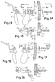
- Figs. 13 to 15 illustrate a different system of construction of the pads 31 for support on the nose.
- each pad 31 is carried by a respective stirrup 33 which forms an eyelet 33A and a terminal hook portion 33B which engages on the bridge 5, as shown in particular in Fig. 13.
- the hook 33B prevents the rotation of the pad 31 once the screw 23 has been tightened.
- Figs. 16 to 18 show, finally, a variant in which the stirrups which carry the pads 31 are constructed from terminal ends 5D of the wire forming the bridge 5. Said wire also forms eyelets 5C into which the tightening screws 23 are inserted.
Landscapes
- Physics & Mathematics (AREA)
- Health & Medical Sciences (AREA)
- General Physics & Mathematics (AREA)
- Ophthalmology & Optometry (AREA)
- Optics & Photonics (AREA)
- Eyeglasses (AREA)
- Glass Compositions (AREA)
- Inorganic Insulating Materials (AREA)
- Hinges (AREA)
Abstract
Description
- The invention relates to a spectacle frame.
- More particularly, the invention relates to an improvement to a frame comprising: a pair of arms or temples; for each arm, an element for connection to the respective lens and a hinge between each arm and the relevant connecting element.
- Frames of this type are described, for example, in US-A-718,363. In this frame, the arms are each formed by a metal wire which, in the end portion adjacent to the lens, forms a helical spring portion constituting a resilient articulation, and a clip for anchoring to the lens. Each arm is linked to the respective lens just by the fact of the resilient force exerted by the clip, and this does not ensure a reliable connection between arm and lens.
- For the purpose of guaranteeing a more secure connection, alternative systems of connection between lenses and frame, and in particular between lenses and intermediate bridge, as well as between lenses and arms, have been devised. By way of example, US-A-4,502,765 contains a description of a connecting system in which each lens exhibits eyelet holes and in which in each hole there are inserted two pivot pins which are spaced from one another and which are integral with the intermediate bridge or with the arm. A locking screw is inserted between the pivot pins. This locking system exhibits the disadvantage that the eyelet hole in the lens is difficult and costly to construct. Furthermore, this hole exhibits sharp corners which constitute points of weakening and of initiation of phenomena of breakage of the lens.
- In other known spectacles there is provided a circular hole, through which there passes the screw, surrounded by a resilient sleeve. The disadvantage of this solution is represented by the fact that the tightening of the screw gives rise to an expansion of the sleeve and consequently a breakage of the lens in correspondence with the hole. Spectacles of this type are illustrated, for example, in FOCUS, No. 6/94,
page 47, but in a version having a semi-surround for the lenses. - EP-B-0 256 098 discloses a frame for spectacles having connecting elements and relevant arms made by separate portions of wire. Each arm and the relevant connecting element are mutually articulated by a hinge formed by a wire portion making up the pivot and by a helically wound end portion surrounding the pivot and formed by the arm. This arrangement is expensive and the hinge difficult to produce.
- The subject of the present invention is constituted by a frame which overcomes the disadvantages of the conventional frames.
- In particular, a first subject of the present invention is the construction of a frame of the initially mentioned type, in which the arms and possibly the intermediate bridge can be linked to the lenses in a secure and reliable manner, without the risk of a relative movement with respect to the lenses and without risks of breakage of said lenses.
- A further subject of the present invention is a frame which is of low cost and which is easy to assemble.
- The aforementioned objects and further objects and advantages, which will become clear to persons skilled in the art upon reading the text which follows, are obtained with a frame according to claim 1.
- Further advantageous features of the frame according to the invention are described in the text which follows, with reference to a number of embodiments, and in the appended claims.
- The invention will be better understood upon following the description and the accompanying drawing, which shows a non-limiting practical exemplification of said invention. In the drawing:
- Fig. 1 shows a front view of a pair of spectacles equipped with a frame according to the present invention;
- Fig. 2 shows an exploded view of the elements constituting the connection between the arm and the lens;
- Fig. 3 shows a view according to III-III of Fig. 2;
- Fig. 4 shows a view according to IV-IV of Fig. 2;
- Figs. 4A and 4B show a different embodiment of the articulating hinge between the arm and the connecting element;
- Fig. 5 shows a detail, in front view, of the pad for support on the nose;
- Fig. 6 shows an exploded view of the elements for connecting the pad and the intermediate bridge to the lens;
- Fig. 7 shows a view according to VII-VII of Fig. 6;
- Fig. 8 shows, separately, in front view, the element carrying the pad for support on the nose;
- Fig. 9 shows, separately, one lens;
- Fig. 10 shows a view similar to the view of Fig. 4, of a slightly modified embodiment;
- Fig. 11 shows an exploded view, similar to the view of Fig. 2, in a further embodiment;
- Fig. 12 shows a view according to XII-XII of Fig. 11;
- Fig. 13 shows a front view, similar to Fig. 5, in a modified embodiment;
- Fig. 14 shows an exploded view of the system for connecting the pad for support on the nose in the embodiment of Fig. 13;
- Fig. 15 shows a view according to XV-XV of Fig. 14;
- Fig. 16 shows a view, similar to the view of Fig. 13, in a modified embodiment;
- Fig. 17 shows an exploded view, similar to the view of Fig. 14, of the embodiment of Fig. 16; and
- Fig. 18 shows a view according to XVIII-XVIII of Fig. 17.
- Figs. 1 to 9 show all the elements of a first embodiment of the frame according to the invention. Reference numeral 1 generally indicates, in Fig. 1, a pair of spectacles having two lenses L which are self-supporting, or without surround, and to which the
arms 3 and theintermediate bridge 5 are connected. Eacharm 3 is connected to the respective lens by means of a connectingelement 7, by means of a hinge 9 between the arm and the connecting element, which hinge permits the articulation of said arm. - The
arms 3, theintermediate bridge 5 and theconnecting elements 7 are constructed of resilient and non-allergic metal wire, such as for example stainless steel, gold or its alloys, titanium, or the like. - The end of each
arm 3, which is linked to the respective connectingelement 7, is bent to form aneyelet 3A and aloop 3B. Eachintermediate element 7 forms, at a first end, ahelical spring 7A, the external diameter of which is of dimensions such as to be inserted, with slight forcing, in a hole LF of the respective lens. The second end of eachintermediate element 7 forms aneyelet 7B which, in the assembled condition, is disposed coaxially with theeyelet 3A to form an articulation hinge, supplemented by a pivot pin, constituted by ascrew 13 and by anut 14 or by an appropriately smoothed washer. The opening oscillation of each arm is limited by the abutment of theloop 3B against the connectingelement 7. During this oscillation, the risk of unscrewing of thescrew 13 from the washer or from thenut 14 is avoided in that both the head of the screw and the nut are in contact with surfaces of the wire forming thearm 3, and accordingly any relative sliding movement between screw and arm or between nut and arm is prevented. - Between the two
ends element 7 forms a U-shaped loop indicated by 7C, one branch of which is caught in a notch LT along the peripheral edge of the lens L. - The locking of each connecting
element 7, and thus of therespective arm 3, to the pertinent lens L takes place by means of ascrew 15 which is inserted in thespring 7A and engages in a threadedbushing 17 with which twoattachments 19 are integral, which attachments, in the assembled condition, embrace a portion of the respective connectingelement 7, and thus the portion between the end which is helically wound to form thespring 7A and the U-shaped loop 7C. In this way, the threadedbushing 17 is fixed against rotation and accidental unscrewing. Awasher 21 of plastic or similar material is disposed between the head of thescrew 15 and the front surface of the lens L. - Figs. 4A and 4B show a modified embodiment of the hinge 9. More particularly, Fig. 4A shows an exploded axonometric view of the hinge and Fig. 4B shows a cross section along a plane containing the axis of the hinge. According to this embodiment, the
arm 3 forms, at its own end fixed to the connectingelement 7, twoeyelets 3X, 3Y which are spaced from one another along the axis of the hinge. Between the twoeyelets 3X, 3Y there is inserted aneyelet 7X formed by the corresponding end of the connectingelement 7. The mutual locking takes place by means of the insertion, under pressure, of asphere 8, the diameter of which corresponds to the internal diameter of theeyelet 7X. Theeyelets 3X and 3Y of lesser diameter retain the sphere in its position and are constructed in such a manner as to permit the insertion of the sphere in its working position by simple pressure and radial deformation of one of theeyelets 3X or 3Y, according to whether the sphere is inserted from one side or from the other. This configuration of the hinge is particularly simple to construct and to assemble, and avoids any problem of unscrewing, which may arise with the conventional hinges making use of screw means. - Figs. 5 to 8 show the system for locking the
bridge 5 to the lenses L. For this purpose, the terminal ends of the wire forming thebridge 5 are helically wound to form respectivehelical springs 5A, similar to thesprings 7A formed with the wire of the connectingelement 7. Thesprings 5A are inserted in corresponding holes LF' (Fig. 9) of the respective lens L, which are identical with the holes LF. - A
screw 23 is inserted coaxially in eachspring 5A and engages into a corresponding threaded bushing ornut 25, similar to the threadedbushing 17 and exhibitingattachments attachment 29 is extended so as to form a stirrup, to which is integrally fixed therespective pad 31 for support of the frame on the nose. - The metal wire forming the
bridge 5 exhibits twointermediate portions 5B which engage in corresponding notches LT' constructed peripherally along the edge of the lens. In this way, once thescrews 23 have been tightened, any relative movement between the lenses L and thebridge 5 is prevented. - Figs. 10 to 18 show a number of constructional variants of the frame which is described in detail with reference to Figs. 1 to 9. Identical numerals are used to indicate identical or corresponding parts.
- Fig. 10 shows a variant embodiment of the system for locking the connecting
element 7 to the lens L. In this configuration, the screw engages on a threaded bushing constituted by a simple nut 17A, having no anti-unscrewing attachments. Between the nut 17A and the rear surface of the lens L there is disposed asecond washer 21. - Figs. 11 and 12 show a variant of construction of the articulation hinge between
arm 3 and connectingelement 7. In this case, the articulation is obtained by means of acentral pivot pin 13, inserted in twoeyelets arm 3 and by the connectingelement 7 respectively. In this case, the connectingelement 7 forms adouble eyelet 7B and between the two turns of the double eyelet there is inserted theeyelet 3A formed by the end of thearm 3. - Figs. 13 to 15 illustrate a different system of construction of the
pads 31 for support on the nose. In this case, eachpad 31 is carried by arespective stirrup 33 which forms aneyelet 33A and aterminal hook portion 33B which engages on thebridge 5, as shown in particular in Fig. 13. Thehook 33B prevents the rotation of thepad 31 once thescrew 23 has been tightened. - Figs. 16 to 18 show, finally, a variant in which the stirrups which carry the
pads 31 are constructed from terminal ends 5D of the wire forming thebridge 5. Said wire also forms eyelets 5C into which the tightening screws 23 are inserted. - The various illustrated variants can be combined with one another according to any arrangement.
- It is understood that the drawing shows only an exemplification given only by way of practical demonstration of the invention, it being possible for this invention to vary in forms and arrangements without nevertheless departing from the scope of the concept which forms the basis of said invention. The possible presence of reference numerals in the appended claims has the purpose of facilitating the reading of the claims with reference to the description and to the drawing, and does not limit the scope of the protection represented by the claims.
Claims (6)
- A frame for spectacles comprising: a pair of arms (3); for each arm, an element (7) for connection to the respective lens (L); each arm (3) being connected to the relevant connecting element (7) by means of a hinge, said arms and said connecting elements being constructed of metal wire,
characterized in that
each of said hinges includes:- a first eyelet (7B; 7X; 3A) formed by said arm (3) or said connecting element (7);- two spaced and substantially axially aligned second eyelets (3A, 3B; 3X, 3Y; 7B, 7B) formed by said connecting element (7) or said arm (3);- and a pivoting member (13, 14; 8; 13) extending coaxially to said first and said second eyelets. - Frame according to claim 1, in which said pivoting member includes a screw (13) and a corresponding nut (14).
- Frame according to claim 1, in which said pivoting member is a spherical element (8) retained between said first and said second eyelets.
- Frame according to claim 3, in which said arm (3) forms two eyelets (3X, 3Y) which are substantially coaxial and spaced along the common axis, said intermediate element (7) forms an eyelet (7X) of greater diameter than the eyelets (3X, 3Y) formed by said arm and disposed coaxially with respect to these and between these, the spherical element (8) being caught and retained between the three eyelets (3X, 3Y, 7X).
- Frame according to one or more of claims 1 to 4, in which the terminal end of each arm forms an abutment which limits the opening oscillation of the arm.
- Spectacles comprising a pair of lenses and a frame, said spectacles being characterized in that said frame is constructed according to one or more of the preceding claims.
Applications Claiming Priority (5)
| Application Number | Priority Date | Filing Date | Title |
|---|---|---|---|
| ITFI940077 | 1994-07-11 | ||
| IT94FI000077 IT234446Y1 (en) | 1994-07-11 | 1994-07-11 | GLASSES ENTIRELY BUILT OR WITH STEEL WIRE OR WITH GOLD WIRE OR WITH TITANIUM WIRE OF A DIAMETER LOWER THAN THE MILLIMETER. |
| ITFI940122 IT234483Y1 (en) | 1994-11-17 | 1994-11-17 | FRAME FOR GLASSES WITHOUT CIRCLING |
| ITFI940122 | 1994-11-17 | ||
| EP95906470A EP0772793A1 (en) | 1994-07-11 | 1995-01-04 | Frame for spectacles without surround |
Related Parent Applications (2)
| Application Number | Title | Priority Date | Filing Date |
|---|---|---|---|
| EP95906470A Division EP0772793A1 (en) | 1994-07-11 | 1995-01-04 | Frame for spectacles without surround |
| EP95906470.0 Division | 1996-02-26 |
Publications (3)
| Publication Number | Publication Date |
|---|---|
| EP0721134A2 true EP0721134A2 (en) | 1996-07-10 |
| EP0721134A3 EP0721134A3 (en) | 1996-07-17 |
| EP0721134B1 EP0721134B1 (en) | 1997-11-12 |
Family
ID=26330531
Family Applications (3)
| Application Number | Title | Priority Date | Filing Date |
|---|---|---|---|
| EP96200225A Expired - Lifetime EP0721134B1 (en) | 1994-07-11 | 1995-01-04 | Frame for spectacles with improved hinge for the temples |
| EP95906470A Withdrawn EP0772793A1 (en) | 1994-07-11 | 1995-01-04 | Frame for spectacles without surround |
| EP96200227A Expired - Lifetime EP0717301B1 (en) | 1994-07-11 | 1995-01-04 | Frame for spectacles |
Family Applications After (2)
| Application Number | Title | Priority Date | Filing Date |
|---|---|---|---|
| EP95906470A Withdrawn EP0772793A1 (en) | 1994-07-11 | 1995-01-04 | Frame for spectacles without surround |
| EP96200227A Expired - Lifetime EP0717301B1 (en) | 1994-07-11 | 1995-01-04 | Frame for spectacles |
Country Status (9)
| Country | Link |
|---|---|
| US (1) | US5781270A (en) |
| EP (3) | EP0721134B1 (en) |
| JP (1) | JP2744851B2 (en) |
| CN (1) | CN1141677A (en) |
| AT (2) | ATE165172T1 (en) |
| AU (1) | AU1465295A (en) |
| DE (2) | DE69502077T2 (en) |
| ES (1) | ES2109827T3 (en) |
| WO (1) | WO1996002014A1 (en) |
Cited By (2)
| Publication number | Priority date | Publication date | Assignee | Title |
|---|---|---|---|---|
| WO1997023803A1 (en) * | 1995-12-22 | 1997-07-03 | Ticoline A/S | Hinge structure for eyeglasses or eyeglass frames and eyeglasses and eyeglass frames, and a method of fitting a lens into an eyeglass frame |
| EP0950916A1 (en) * | 1998-04-15 | 1999-10-20 | Bottega D'arte In Firenze S.R.L. | System consisting of a spectacle frame and a support for protective sun lenses |
Families Citing this family (32)
| Publication number | Priority date | Publication date | Assignee | Title |
|---|---|---|---|---|
| IT1280837B1 (en) * | 1995-03-31 | 1998-02-11 | Pietro Devercelli | PERFECT FRAME FOR EYEWEAR. |
| IT1281251B1 (en) * | 1995-12-06 | 1998-02-17 | Armando Rattaro | FIXING DEVICE FOR BRIDGE AND ARMS TO LENSES OF FRAMELESS GLASSES. |
| FR2747482A1 (en) * | 1996-04-16 | 1997-10-17 | Vision Universelle Europ | Flexible joint for spectacle legs |
| WO1997041480A1 (en) * | 1996-05-02 | 1997-11-06 | Safilo Societa' Azionaria Fabbrica Italiana Lavorazione Occhiali S.P.A | Improved spectacles |
| IT240637Y1 (en) * | 1996-05-03 | 2001-04-02 | Filospiave Group S P A | FRAME FOR GLASSES WITH HIGH STRUCTURAL SIMPLICITY AND LIGHTNESS |
| EP0898728A1 (en) * | 1996-05-16 | 1999-03-03 | Bottega D'arte In Firenze S.R.L. | Wire frame for spectacles |
| IT1286108B1 (en) * | 1996-06-18 | 1998-07-07 | Pietro Devercelli | PERFECTED HINGE FOR A GLASSES FRAME. |
| IT242021Y1 (en) * | 1996-08-05 | 2001-05-24 | Gb Srl | SHAFT FOR GLASSES WITH ELASTICIZATION CAM TO BE APPLIED SHAPE OF SHAPED WIRE. |
| DE29614235U1 (en) * | 1996-08-16 | 1997-12-18 | Owp Brillen Gmbh | Arrangement for connecting a temple or a cheek piece to glasses |
| FR2754914B1 (en) * | 1996-10-21 | 1998-12-18 | L Amy | METHOD OF LINKING BETWEEN A BRANCH AND A EYEWEAR FRONT AND EYEGLASS HINGE |
| IT1286861B1 (en) * | 1996-10-22 | 1998-07-17 | Bottega Arte Firenze Srl | FRAME FOR WIRED GLASSES WITH CIRCLE |
| FR2754913B1 (en) * | 1996-10-23 | 1998-12-11 | Airess | FRAME OF WIRE GLASSES |
| AU4699597A (en) * | 1996-10-25 | 1998-05-22 | Pro Design International A/S | A pair of spectacles |
| JP2001511901A (en) * | 1997-03-10 | 2001-08-14 | サフィロ・ソシエタ・アツィオナリア・ファブリカ・イタリアナ・ラボラツィオーネ・オクチアリ・エス・ピー・エー | Improved eyeglass frame |
| IT242923Y1 (en) * | 1997-03-12 | 2002-02-04 | Cosmo Line Optic Sas Di Gaiga | FRAME STRUCTURE FOR TITANIUM WIRE GLASSES WITHOUT SCREWS |
| IT1291824B1 (en) * | 1997-04-08 | 1999-01-21 | Bottega Arte Firenze Srl | FRAME FOR GLASSES WITH ANTI-UNSCREWING SCREW HINGE |
| US5818568A (en) * | 1997-05-07 | 1998-10-06 | Eye-Protor Kobayashi Inc. | Eyeglass frame assembly having screw-less hinges |
| ITVR970035A1 (en) * | 1997-05-09 | 1998-11-09 | Bline Optic Srl | HOLDING ELEMENT FOR GOGGLES SUPPORT |
| JP3133965B2 (en) * | 1997-09-11 | 2001-02-13 | 株式会社小林 | Eyeglass parts connection structure |
| EP0997763A1 (en) * | 1998-10-29 | 2000-05-03 | Stepper Limited | Spectacles |
| US6050685A (en) * | 1999-08-05 | 2000-04-18 | Lin; Haan-Yeou | Eyeglasses without a frame |
| DE19958005C1 (en) * | 1999-12-02 | 2001-07-26 | Rainer Weber | glasses |
| EP1164410A1 (en) * | 2000-06-16 | 2001-12-19 | Arcadio Vignato | Eyeglasses of the type which are free of mounting and having supplementary structures |
| FR2811773B1 (en) * | 2000-07-17 | 2002-10-11 | Timon | GLASSES WITH WIRED BRANCHES |
| ITFI20010044A1 (en) * | 2001-03-16 | 2002-09-16 | Bottega Arte Firenze Srl | WIRE FRAME WITHOUT CIRCLE FOR GLASSES AND GLASSES INCLUDING THE FRAME |
| FR2826463B1 (en) * | 2001-06-21 | 2003-11-14 | Francois Lambert | NEW MOUNTING SYSTEM FOR EYEWEAR BRANCHES |
| ITGE20010100A1 (en) * | 2001-12-21 | 2003-06-21 | Armando Rattaro | METHOD OF ASSEMBLING GLASSES PROVIDED WITH OPEN FRAME AND DEVICE TO IMPLEMENT THIS METHOD. |
| ITTV20020085A1 (en) * | 2002-07-22 | 2004-01-22 | Foval Srl | SIMPLIFIED HINGE DEVICE AND AUCTION SO OBTAINED, ESPECIALLY FOR GLASSES FRAMES |
| WO2004011988A1 (en) * | 2002-07-25 | 2004-02-05 | Paris Miki Inc. | Hinge mechanism of a pair of spectacles |
| US20160178926A1 (en) * | 2013-09-18 | 2016-06-23 | Yuet-Charn Leung | Modular glasses and method for manufacturing same |
| CN105204178B (en) * | 2014-06-03 | 2019-06-14 | 郑永林 | Configure the glasses of flexible nose-pad bracket |
| GB2582324A (en) * | 2019-03-19 | 2020-09-23 | Derek Snelgrove John | Spectacles |
Citations (5)
| Publication number | Priority date | Publication date | Assignee | Title |
|---|---|---|---|---|
| US962549A (en) * | 1910-06-28 | Lewis H Broome | Temple for eyeglasses. | |
| GB191311431A (en) * | 1913-05-16 | 1913-10-16 | Louis Blanc | Improvements in Spectacles and the like. |
| US5073020A (en) * | 1988-12-19 | 1991-12-17 | Paul Jorn Lindberg | Eyeglasses having oblong receiving means |
| WO1992008158A1 (en) * | 1990-10-25 | 1992-05-14 | Jan Houmand | Spectacles |
| WO1994002876A1 (en) * | 1992-07-17 | 1994-02-03 | Murai Co., Ltd. | Spectacles |
Family Cites Families (4)
| Publication number | Priority date | Publication date | Assignee | Title |
|---|---|---|---|---|
| US718363A (en) * | 1902-04-30 | 1903-01-13 | Emil L Lembke | Temple and spring-clamp for lenses or the like. |
| US943085A (en) * | 1909-05-01 | 1909-12-14 | Sydney S Lawrence | Spectacles, eyeglasses, and the like. |
| FR447381A (en) * | 1912-02-01 | 1912-12-31 | Robert James Fleming | Improvements to the eyeglasses or nose clip to glasses not encased in a frame |
| GB523295A (en) * | 1938-10-27 | 1940-07-10 | American Optical Corp | Improvements in ophthalmic mountings |
-
1995
- 1995-01-04 DE DE69502077T patent/DE69502077T2/en not_active Expired - Fee Related
- 1995-01-04 CN CN95191793A patent/CN1141677A/en active Pending
- 1995-01-04 AU AU14652/95A patent/AU1465295A/en not_active Abandoned
- 1995-01-04 AT AT96200227T patent/ATE165172T1/en not_active IP Right Cessation
- 1995-01-04 WO PCT/IT1995/000001 patent/WO1996002014A1/en not_active Application Discontinuation
- 1995-01-04 JP JP8504218A patent/JP2744851B2/en not_active Expired - Lifetime
- 1995-01-04 AT AT96200225T patent/ATE160227T1/en not_active IP Right Cessation
- 1995-01-04 EP EP96200225A patent/EP0721134B1/en not_active Expired - Lifetime
- 1995-01-04 US US08/615,276 patent/US5781270A/en not_active Expired - Fee Related
- 1995-01-04 EP EP95906470A patent/EP0772793A1/en not_active Withdrawn
- 1995-01-04 EP EP96200227A patent/EP0717301B1/en not_active Expired - Lifetime
- 1995-01-04 DE DE69501036T patent/DE69501036T2/en not_active Expired - Fee Related
- 1995-01-04 ES ES96200225T patent/ES2109827T3/en not_active Expired - Lifetime
Patent Citations (5)
| Publication number | Priority date | Publication date | Assignee | Title |
|---|---|---|---|---|
| US962549A (en) * | 1910-06-28 | Lewis H Broome | Temple for eyeglasses. | |
| GB191311431A (en) * | 1913-05-16 | 1913-10-16 | Louis Blanc | Improvements in Spectacles and the like. |
| US5073020A (en) * | 1988-12-19 | 1991-12-17 | Paul Jorn Lindberg | Eyeglasses having oblong receiving means |
| WO1992008158A1 (en) * | 1990-10-25 | 1992-05-14 | Jan Houmand | Spectacles |
| WO1994002876A1 (en) * | 1992-07-17 | 1994-02-03 | Murai Co., Ltd. | Spectacles |
Cited By (4)
| Publication number | Priority date | Publication date | Assignee | Title |
|---|---|---|---|---|
| WO1997023803A1 (en) * | 1995-12-22 | 1997-07-03 | Ticoline A/S | Hinge structure for eyeglasses or eyeglass frames and eyeglasses and eyeglass frames, and a method of fitting a lens into an eyeglass frame |
| EP1326125A2 (en) * | 1995-12-22 | 2003-07-09 | Ticoline A/S | Hinge structure for eyeglasses or eyeglass frames and eyeglasses and eyeglass frames, and a method of fitting a lens into an eyeglass frame |
| EP1326125A3 (en) * | 1995-12-22 | 2003-09-10 | Copenhagen Eyes A/S | Hinge structure for eyeglasses or eyeglass frames and eyeglasses and eyeglass frames, and a method of fitting a lens into an eyeglass frame |
| EP0950916A1 (en) * | 1998-04-15 | 1999-10-20 | Bottega D'arte In Firenze S.R.L. | System consisting of a spectacle frame and a support for protective sun lenses |
Also Published As
| Publication number | Publication date |
|---|---|
| DE69501036D1 (en) | 1997-12-18 |
| DE69502077T2 (en) | 1998-10-15 |
| DE69502077D1 (en) | 1998-05-20 |
| CN1141677A (en) | 1997-01-29 |
| EP0721134B1 (en) | 1997-11-12 |
| JPH09507924A (en) | 1997-08-12 |
| EP0772793A1 (en) | 1997-05-14 |
| JP2744851B2 (en) | 1998-04-28 |
| ATE160227T1 (en) | 1997-11-15 |
| DE69501036T2 (en) | 1998-03-12 |
| EP0717301A2 (en) | 1996-06-19 |
| ATE165172T1 (en) | 1998-05-15 |
| WO1996002014A1 (en) | 1996-01-25 |
| EP0717301B1 (en) | 1998-04-15 |
| US5781270A (en) | 1998-07-14 |
| ES2109827T3 (en) | 1998-01-16 |
| EP0717301A3 (en) | 1996-07-24 |
| AU1465295A (en) | 1996-02-09 |
| EP0721134A3 (en) | 1996-07-17 |
Similar Documents
| Publication | Publication Date | Title |
|---|---|---|
| EP0721134B1 (en) | Frame for spectacles with improved hinge for the temples | |
| JPH0774864B2 (en) | Eye mirror | |
| US5684559A (en) | Lens positioning device for spectacles | |
| US6113235A (en) | Eyeglasses frame having elastically deformable rim-to-temple joints | |
| JP3040995B1 (en) | Eyeglass lens fastening mechanism | |
| EP0895114A1 (en) | Eyeglass frame having metal-and-string rims | |
| EP0762178A1 (en) | A structure for rimless spectacles of the type fashioned from wire | |
| JP2533009Y2 (en) | Frameless glasses | |
| EP0796454B1 (en) | Rimless spectacles | |
| EP0898728A1 (en) | Wire frame for spectacles | |
| US5412440A (en) | Rimless spectacles with adjustable temples and lenses | |
| EP0601849A1 (en) | Rimless spectacles | |
| US6464352B1 (en) | Detachable shelter frame for mounting in front of a primary spectacle frame | |
| KR20150112922A (en) | Spectacle frame | |
| CN218647245U (en) | Glasses with elastic legs | |
| US6834954B2 (en) | Spectacles of the type without a surround | |
| WO2004003635A1 (en) | Spectacles hinge | |
| JP3006215U (en) | Spiral joint structure for eyeglass frames | |
| JP3381160B2 (en) | Eyeglass lens fastening structure | |
| JP3011177U (en) | Spiral joint and joint structure for eyeglass frames | |
| JPH1144865A (en) | Mount for semi-rimless spectacles | |
| JPH0322736Y2 (en) | ||
| JP3001671U (en) | Eye mirror | |
| JP3073359U (en) | Glasses frame | |
| JP2002311391A (en) | Spectacle frame |
Legal Events
| Date | Code | Title | Description |
|---|---|---|---|
| PUAI | Public reference made under article 153(3) epc to a published international application that has entered the european phase |
Free format text: ORIGINAL CODE: 0009012 |
|
| PUAL | Search report despatched |
Free format text: ORIGINAL CODE: 0009013 |
|
| AK | Designated contracting states |
Kind code of ref document: A2 Designated state(s): AT BE CH DE DK ES FR GB IE IT LI LU NL SE |
|
| AK | Designated contracting states |
Kind code of ref document: A3 Designated state(s): AT BE CH DE DK ES FR GB IE IT LI LU NL SE |
|
| 17P | Request for examination filed |
Effective date: 19960926 |
|
| ITCL | It: translation for ep claims filed |
Representative=s name: UFFICIO TECNICO ING. A. MANNUCCI |
|
| GRAG | Despatch of communication of intention to grant |
Free format text: ORIGINAL CODE: EPIDOS AGRA |
|
| GRAH | Despatch of communication of intention to grant a patent |
Free format text: ORIGINAL CODE: EPIDOS IGRA |
|
| 17Q | First examination report despatched |
Effective date: 19970422 |
|
| GRAH | Despatch of communication of intention to grant a patent |
Free format text: ORIGINAL CODE: EPIDOS IGRA |
|
| RAP1 | Party data changed (applicant data changed or rights of an application transferred) |
Owner name: BOTTEGA D'ARTE IN FIRENZE S.R.L. |
|
| GRAA | (expected) grant |
Free format text: ORIGINAL CODE: 0009210 |
|
| AC | Divisional application: reference to earlier application |
Ref document number: 772793 Country of ref document: EP |
|
| AK | Designated contracting states |
Kind code of ref document: B1 Designated state(s): AT BE CH DE DK ES FR GB IE IT LI LU NL SE |
|
| PG25 | Lapsed in a contracting state [announced via postgrant information from national office to epo] |
Ref country code: NL Free format text: LAPSE BECAUSE OF FAILURE TO SUBMIT A TRANSLATION OF THE DESCRIPTION OR TO PAY THE FEE WITHIN THE PRESCRIBED TIME-LIMIT Effective date: 19971112 Ref country code: LI Free format text: LAPSE BECAUSE OF FAILURE TO SUBMIT A TRANSLATION OF THE DESCRIPTION OR TO PAY THE FEE WITHIN THE PRESCRIBED TIME-LIMIT Effective date: 19971112 Ref country code: DK Free format text: LAPSE BECAUSE OF NON-PAYMENT OF DUE FEES Effective date: 19971112 Ref country code: CH Free format text: LAPSE BECAUSE OF FAILURE TO SUBMIT A TRANSLATION OF THE DESCRIPTION OR TO PAY THE FEE WITHIN THE PRESCRIBED TIME-LIMIT Effective date: 19971112 Ref country code: BE Free format text: LAPSE BECAUSE OF FAILURE TO SUBMIT A TRANSLATION OF THE DESCRIPTION OR TO PAY THE FEE WITHIN THE PRESCRIBED TIME-LIMIT Effective date: 19971112 |
|
| REF | Corresponds to: |
Ref document number: 160227 Country of ref document: AT Date of ref document: 19971115 Kind code of ref document: T |
|
| REG | Reference to a national code |
Ref country code: CH Ref legal event code: EP |
|
| REF | Corresponds to: |
Ref document number: 69501036 Country of ref document: DE Date of ref document: 19971218 |
|
| PGFP | Annual fee paid to national office [announced via postgrant information from national office to epo] |
Ref country code: FR Payment date: 19971230 Year of fee payment: 4 |
|
| PG25 | Lapsed in a contracting state [announced via postgrant information from national office to epo] |
Ref country code: LU Free format text: LAPSE BECAUSE OF NON-PAYMENT OF DUE FEES Effective date: 19980104 |
|
| PG25 | Lapsed in a contracting state [announced via postgrant information from national office to epo] |
Ref country code: IE Free format text: LAPSE BECAUSE OF NON-PAYMENT OF DUE FEES Effective date: 19980112 |
|
| REG | Reference to a national code |
Ref country code: ES Ref legal event code: FG2A Ref document number: 2109827 Country of ref document: ES Kind code of ref document: T3 |
|
| PGFP | Annual fee paid to national office [announced via postgrant information from national office to epo] |
Ref country code: AT Payment date: 19980126 Year of fee payment: 4 |
|
| PGFP | Annual fee paid to national office [announced via postgrant information from national office to epo] |
Ref country code: DE Payment date: 19980203 Year of fee payment: 4 |
|
| PG25 | Lapsed in a contracting state [announced via postgrant information from national office to epo] |
Ref country code: SE Free format text: LAPSE BECAUSE OF FAILURE TO SUBMIT A TRANSLATION OF THE DESCRIPTION OR TO PAY THE FEE WITHIN THE PRESCRIBED TIME-LIMIT Effective date: 19980212 |
|
| ET | Fr: translation filed | ||
| NLV1 | Nl: lapsed or annulled due to failure to fulfill the requirements of art. 29p and 29m of the patents act | ||
| REG | Reference to a national code |
Ref country code: CH Ref legal event code: PL |
|
| PLBE | No opposition filed within time limit |
Free format text: ORIGINAL CODE: 0009261 |
|
| STAA | Information on the status of an ep patent application or granted ep patent |
Free format text: STATUS: NO OPPOSITION FILED WITHIN TIME LIMIT |
|
| 26N | No opposition filed | ||
| PG25 | Lapsed in a contracting state [announced via postgrant information from national office to epo] |
Ref country code: GB Free format text: LAPSE BECAUSE OF NON-PAYMENT OF DUE FEES Effective date: 19990104 Ref country code: AT Free format text: LAPSE BECAUSE OF NON-PAYMENT OF DUE FEES Effective date: 19990104 |
|
| PGFP | Annual fee paid to national office [announced via postgrant information from national office to epo] |
Ref country code: ES Payment date: 19990104 Year of fee payment: 5 |
|
| GBPC | Gb: european patent ceased through non-payment of renewal fee |
Effective date: 19990104 |
|
| PG25 | Lapsed in a contracting state [announced via postgrant information from national office to epo] |
Ref country code: FR Free format text: LAPSE BECAUSE OF NON-PAYMENT OF DUE FEES Effective date: 19990930 |
|
| PG25 | Lapsed in a contracting state [announced via postgrant information from national office to epo] |
Ref country code: DE Free format text: LAPSE BECAUSE OF NON-PAYMENT OF DUE FEES Effective date: 19991103 |
|
| REG | Reference to a national code |
Ref country code: FR Ref legal event code: ST |
|
| PG25 | Lapsed in a contracting state [announced via postgrant information from national office to epo] |
Ref country code: ES Free format text: LAPSE BECAUSE OF NON-PAYMENT OF DUE FEES Effective date: 20000105 |
|
| REG | Reference to a national code |
Ref country code: ES Ref legal event code: FD2A Effective date: 20010910 |
|
| PG25 | Lapsed in a contracting state [announced via postgrant information from national office to epo] |
Ref country code: IT Free format text: LAPSE BECAUSE OF NON-PAYMENT OF DUE FEES;WARNING: LAPSES OF ITALIAN PATENTS WITH EFFECTIVE DATE BEFORE 2007 MAY HAVE OCCURRED AT ANY TIME BEFORE 2007. THE CORRECT EFFECTIVE DATE MAY BE DIFFERENT FROM THE ONE RECORDED. Effective date: 20050104 |