EP0721040A2 - Haltevorrichtung - Google Patents
Haltevorrichtung Download PDFInfo
- Publication number
- EP0721040A2 EP0721040A2 EP95308736A EP95308736A EP0721040A2 EP 0721040 A2 EP0721040 A2 EP 0721040A2 EP 95308736 A EP95308736 A EP 95308736A EP 95308736 A EP95308736 A EP 95308736A EP 0721040 A2 EP0721040 A2 EP 0721040A2
- Authority
- EP
- European Patent Office
- Prior art keywords
- connecting member
- retaining means
- bore
- retaining
- operating position
- Prior art date
- Legal status (The legal status is an assumption and is not a legal conclusion. Google has not performed a legal analysis and makes no representation as to the accuracy of the status listed.)
- Granted
Links
Images


Classifications
-
- E—FIXED CONSTRUCTIONS
- E05—LOCKS; KEYS; WINDOW OR DOOR FITTINGS; SAFES
- E05B—LOCKS; ACCESSORIES THEREFOR; HANDCUFFS
- E05B73/00—Devices for locking portable objects against unauthorised removal; Miscellaneous locking devices
-
- E—FIXED CONSTRUCTIONS
- E05—LOCKS; KEYS; WINDOW OR DOOR FITTINGS; SAFES
- E05B—LOCKS; ACCESSORIES THEREFOR; HANDCUFFS
- E05B15/00—Other details of locks; Parts for engagement by bolts of fastening devices
- E05B15/0093—Weight arrangements in locks; gravity activated lock parts
-
- E—FIXED CONSTRUCTIONS
- E05—LOCKS; KEYS; WINDOW OR DOOR FITTINGS; SAFES
- E05B—LOCKS; ACCESSORIES THEREFOR; HANDCUFFS
- E05B35/00—Locks for use with special keys or a plurality of keys ; keys therefor
- E05B35/008—Locks for use with special keys or a plurality of keys ; keys therefor for simple tool-like keys
Definitions
- This invention relates to a fastening device, and particularly, but not exclusively, to a fastening device for resisting removal of objects by thieves or vandals.
- a fastening device comprises a connecting member, a body having a bore therein which is inclined in use of the device, and retaining means movable downwardly along the bore, under the action of its own weight, the retaining means having an operating position in the bore in which it is engageable with the connecting member so as to prevent separation of the connecting member therefrom.
- actuating means is provided for moving the retaining means away from its operating position to enable separation of the connecting member therefrom.
- an object to be secured is attached to the connecting member, and the body is firmly installed at a fixed location. After engagement between the retaining means and the connecting member, subsequent operation of the actuating means by an authorised person will enable the object to be removed from the fixed location with minimum difficulty.
- an example of a further use of the invention is for preventing unauthorised removal of valuable goods from shops. Still another use is for securing valuable or vulnerable garden ornaments or furniture.
- the body of the device is desirably provided with an opening which intersects with the bore so as to enable the connecting member to be inserted within the body for engagement with the retaining means.
- the device may be conveniently provided with displacing means for moving the retaining means away from its operating position during insertion of the connecting member, but allowing the retaining means to return to the operating position under the action of its own weight to engage the connecting member after insertion.
- the displacing means conveniently comprises a camming surface on the connecting member.
- the displacing means may comprise the actuating means.
- the connecting member comprises balking means for urging the retaining means against a stop to ensure that the retaining means remains in the operating position when an attempt is made to remove the connecting member from engagement with the retaining means.
- the stop may conveniently comprise an end wall of the bore.
- the wall of the bore may be shaped so as to urge the retaining means against the stop when attempting to remove the connecting member.
- the connecting member may desirably be adjustable after engagement with the retaining means for example using screw-threaded means, so as to tighten the engagement between the connecting member and the retaining means.
- the retaining means desirably comprises a ball.
- the connecting member preferably comprises a ring or a hook for engagement with the retaining means, an outwardly directed surface of the ring or the hook conveniently comprising the camming surface of the displacing means, with an inwardly directed surface of the ring or the hook also comprising a camming surface to form said balking means.
- the actuating means preferably comprises a striking member which is operated, either manually or by other means such as electrically driven solenoid means, to strike the retaining means so as to move the retaining means away from its operating position.
- the device may be configured such that a certain level of skill is required by a person in order to coordinate the operation of the actuating means and removal of the connecting member, before the retaining means returns to its operating position. Operation of the actuating means may desirably be adjustable.
- the body of the device may conveniently comprise a plastics moulding.
- the body is preferably provided with a drainage channel to prevent the bore filling with water.
- the opening of the bore is preferably provided with a cover.
- a method of installing the body of the device at a fixed location comprises forming a hole to receive a concrete footing, placing the body in the hole together with a channel means extending above the body, and casting the footing around the body and the channel means such that the channel means remains open to allow insertion of the connecting member into the body.
- a control link is preferably also provided between the body and the surface of the ground, or between the body and a point near to the surface of the ground, for operating the actuating means.
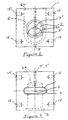
- the body of the device comprises a plastics moulding in the form of a block 1 having an inclined main bore 2 which contains a retaining means in the form of a stainless steel ball 3.
- the opening of the bore is sealed by a cover 4 to prevent the ball dropping out prior to installation, and to prevent the ingress of water and solids through the opening after installation.
- a drainage outlet 5 is provided towards the lower end of the bore.
- a slot 6 Communicating between the bore 2 and the upper face of the block 1 is a slot 6 which intersects both the bore 2 and the drainage outlet 5.
- the slot 6 provides access to the bore 2 for the connecting member 8 shown in Figures 4, 5 and 6.
- the rim of the opening of the slot 6 at the surface of the block 1 is provided with a chamfer 6a to facilitate insertion of the connecting member 8 in use.
- a relatively small bore 7' Coaxial with the main bore 2 is a relatively small bore 7' which connects bore 2 with the outside and provides access for a striker member in the form of a pin (not shown).
- a striker member in the form of a pin (not shown).
- Screw holes 15 may be provided in the sides of the block 1 for use in installation, as described hereinafter.
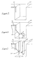
- the upper end of the connecting member 8 in this embodiment comprises a threaded portion 9 which may be screwed into the object to be secured (such as a post 10, the lower end of which is illustrated in Figure 12) in order to join the object to the connecting member prior to use of the device. Also prior to use of the device, the block 1 will have been installed at a fixed location as described hereinafter.
- the lower end 11 of the connecting member 8 comprises a ring 12, the function of which will now be described with reference to Figure 6.
- the lower end 11 of the connecting member 8 is inserted into the slot 6 of block 1, until ring 12 is locked by ball 3 in the position shown in Figure 6.
- the ball 3 must be displaced upwardly along the bore 2 from the operating position shown in Figure 6, in order to allow ring 12 of the connecting member to pass across the bore 2 to the final position shown in Figure 6.
- This displacement is achieved by provision of displacing means in the form of a camming surface 12a forming a lower, outwardly directed surface of the ring 12.
- the direction of insertion of the connecting member 8 is defined by the axis 6b of the slot 6, and camming surface 12a is angled with respect to axis 6b as shown in Figure 6, such that ball 3 is deflected upwardly along bore 2 when camming surface 12a engages with the ball 3 during insertion. Only when the ring has reached the position shown in Figure 6 is the ball 3 free to roll through the ring 12 back to its starting position, thus achieving the locked condition illustrated in Figure 6.
- the striking member located in either bore 7' or 7" must be operated to strike ball 3 and drive it upwardly along bore 2 towards the cover 4.
- the brief interval during which the ball remains in the upper portion of the bore 2 is sufficient to raise connecting member 8 to a position in which the ball can no longer pass back through the ring to lock it in position.
- the connecting member 8 can then be removed fully from the block 1 so that the object attached to the connecting member can be taken away.
- the striking member may be operated by manual, electrical or other actuating means.
- Manual actuating means are utilised in the second embodiment as shown in Figure 13 in a view which corresponds generally to the view of the first embodiment shown in Figure 6.
- Like reference numerals have been used for like parts in Figures 6 and 13.
- the striking member which is in the form of a pin, is indicated by reference 13.
- the striking member 13 is housed in bore 7, and the enlarged opening 7a of the bore 7 is covered by a flexible plate 14. If the centre of plate 14 is hit, for example with the foot, it will distort within enlarged opening 7a so as to project striking member 13 forwardly against ball 3 so driving ball 3 up the inclined bore 2 towards cover 4. Return of striking member 13 from its forward position to the position shown in Figure 13 is achieved by the action of a return spring 15 on a lug 13a on the striking member 13.
- the first stage in the installation is to dig a hole 20 in the ground to receive a concrete footing.
- the hole is illustrated diagrammatically in Figure 7 with the front wall cut away for clarity.
- the hole 20 is extended to one side by a slot 21, the base of which runs at approximately 45° to the horizontal.
- the second stage is to place the block 1 approximately centrally at the base of the hole, and to ensure that it is level, with the opening of slot 6 in the block facing upwards.
- a control link 22 is positioned so that it extends from an attachment with the opening to bore 7" on the block 1 to the surface of the ground, or near to the surface of the ground, along slot 21.
- channel member 23 The next stage in the installation, illustrated in Figure 9, is to place a channel member 23 over the block.
- the front wall of channel member 23 is shown cut away in the drawing for clarity, but is in fact a tubular member of square cross-section, which is apparent in Figure 10.
- a slot 24 is provided one side wall of the channel member 23, extending from the lower edge thereof, in order to allow the channel member to pass over the control link 22.
- the channel member may be joined to the body 1 using screws fastened in holes 15 in the body.
- the channel member may be joined to the body in other ways.
- the channel member and body may be formed to snap-fit together.
- the final stage in installation of the block 1 is to cast the concrete footing 25 around channel member 23 and the communication link 22, as shown in Figure 11, and to cover slot 21 for the communication link, or to fill it with earth, concrete or other suitable material according to requirements.
- the communication link may be held in place by pouring concrete into slot 21.
- the end of the communication link may be hidden below the surface of the ground, so that it can be operated only by persons aware of its location.
- the communication link could be covered with earth, the earth being used to fill the slot 21.
- the device When the concrete has set, the device is ready for use.
- the connecting member 8 is fastened centrally in the lower end of the post, with the ring 12 of the connecting member oriented transversely.
- the end of the post can then be lowered into channel member 23 so that ring 12 enters the slot 6 in block 1 and becomes locked in position by the ball 3.
- the post can only be removed thereafter by use of control link 22 to operate the striking member located in bore 7" of the block 1.
Landscapes
- Hooks, Suction Cups, And Attachment By Adhesive Means (AREA)
- Refuge Islands, Traffic Blockers, Or Guard Fence (AREA)
- Piles And Underground Anchors (AREA)
Applications Claiming Priority (3)
| Application Number | Priority Date | Filing Date | Title |
|---|---|---|---|
| GB9424600A GB2295845B (en) | 1994-12-06 | 1994-12-06 | Fastening device |
| GB9424600 | 1994-12-06 | ||
| US08/736,258 US5819495A (en) | 1994-12-06 | 1996-10-24 | Fastening device |
Publications (3)
| Publication Number | Publication Date |
|---|---|
| EP0721040A2 true EP0721040A2 (de) | 1996-07-10 |
| EP0721040A3 EP0721040A3 (de) | 1997-03-05 |
| EP0721040B1 EP0721040B1 (de) | 2000-11-15 |
Family
ID=26306119
Family Applications (1)
| Application Number | Title | Priority Date | Filing Date |
|---|---|---|---|
| EP95308736A Expired - Lifetime EP0721040B1 (de) | 1994-12-06 | 1995-12-04 | Haltevorrichtung |
Country Status (3)
| Country | Link |
|---|---|
| US (1) | US5819495A (de) |
| EP (1) | EP0721040B1 (de) |
| GB (1) | GB2295845B (de) |
Families Citing this family (2)
| Publication number | Priority date | Publication date | Assignee | Title |
|---|---|---|---|---|
| DE19817729C1 (de) * | 1998-04-21 | 1999-08-12 | Helmut Seidel | Verriegelbare Steckverbindung |
| US8028510B2 (en) * | 2008-02-27 | 2011-10-04 | Teleflex Canada Inc. | Link for a linear actuator |
Family Cites Families (15)
| Publication number | Priority date | Publication date | Assignee | Title |
|---|---|---|---|---|
| GB932795A (en) * | 1960-07-19 | 1963-07-31 | Atomic Energy Authority Uk | Improvements in or relating to ball lock clamping devices |
| GB1361397A (en) * | 1970-12-11 | 1974-07-24 | Gen Descaling Co Ltd | Cover plate assembly |
| US3863975A (en) * | 1971-06-04 | 1975-02-04 | Alvin B Oldenettel | Apparatus for lifting heavy objects |
| US4085916A (en) * | 1974-03-06 | 1978-04-25 | Jorgen Gammelgaard Pedersen | Releasable locking device |
| IT1190964B (it) * | 1981-08-25 | 1988-02-24 | Ken Yamamoto | Meccanismo di bloccaggio ausiliario per valigie,borse e simili articoli |
| AU570500B2 (en) * | 1983-09-14 | 1988-03-17 | Gearhart Australia Limited | Earth anchor member |
| KR900008444B1 (en) * | 1983-10-28 | 1990-11-22 | Ken Yamamoto | Locking device for bag |
| US5024474A (en) * | 1989-10-24 | 1991-06-18 | Selsys Corporation | Locking cam latch mechanism |
| DE4041310A1 (de) * | 1990-12-21 | 1992-06-25 | Herbert Dischinger | Verriegelungsmechanismus fuer einen kofferverschluss |
| US5149153A (en) * | 1991-04-25 | 1992-09-22 | Drewry Thomas L | Self-disengaging locking device |
| US5152562A (en) * | 1991-11-05 | 1992-10-06 | Stevenson John M | Shock-actuated lock with resettable ball |
| DE59300320D1 (de) * | 1992-02-18 | 1995-08-10 | Fatzer Ag | Spiraldrahtseilanker, insbesondere zur Verankerung von Steinschlag- und Lawinenschutzsystemen. |
| US5309691A (en) * | 1992-02-26 | 1994-05-10 | Tolliver Wilbur E | Shear connected structural units |
| US5384993A (en) * | 1993-11-15 | 1995-01-31 | Phillips; Belton R. | Tie down for building structures |
| US5490365A (en) * | 1994-05-11 | 1996-02-13 | Roth; Steven A. | Anchor bolt assembly |
-
1994
- 1994-12-06 GB GB9424600A patent/GB2295845B/en not_active Expired - Fee Related
-
1995
- 1995-12-04 EP EP95308736A patent/EP0721040B1/de not_active Expired - Lifetime
-
1996
- 1996-10-24 US US08/736,258 patent/US5819495A/en not_active Expired - Fee Related
Non-Patent Citations (1)
| Title |
|---|
| None |
Also Published As
| Publication number | Publication date |
|---|---|
| EP0721040A3 (de) | 1997-03-05 |
| EP0721040B1 (de) | 2000-11-15 |
| GB2295845B (en) | 1998-08-19 |
| GB2295845A (en) | 1996-06-12 |
| US5819495A (en) | 1998-10-13 |
| GB9424600D0 (en) | 1995-01-25 |
Similar Documents
| Publication | Publication Date | Title |
|---|---|---|
| US4483506A (en) | Temporary signpost support sleeve and tool for unsetting same | |
| US5337989A (en) | Two-piece self-locking pole stand assembly | |
| US5176437A (en) | Anchor clip for preventing tipping of storage cabinets | |
| US5249831A (en) | Security lock for safes and the like having inertial operated counterweight | |
| US4455795A (en) | Post anchoring device | |
| US6409419B1 (en) | Removable security post assembly | |
| WO1999045209A1 (en) | Self-installing post | |
| CA2052021A1 (en) | Trailer security device and method | |
| RU2001106604A (ru) | Способ запираемой доставки на дом | |
| US5454202A (en) | Flagpole assembly with anti-theft protection | |
| EP0976324B1 (de) | Vorrichtung zum Befestigen von Köderdosen am Erdboden | |
| US6047999A (en) | Mausoleum crypt lock | |
| US5803426A (en) | Locking footing socket to improve post implantation | |
| EP0721040B1 (de) | Haltevorrichtung | |
| GB2199610A (en) | Security bolt | |
| US6732555B1 (en) | Lock for a meter box lid | |
| WO1996023118A1 (en) | Ground fixing | |
| US10518746B1 (en) | Detachable trailer jack locking assembly | |
| US3871284A (en) | Coin box and lock mechanism | |
| US4986406A (en) | Anti-theft parking meter anchoring device | |
| GB2297781A (en) | Retractable post assembly | |
| GB2264730A (en) | Ground anchor | |
| AU585255B2 (en) | Retaining assemblies | |
| US4290636A (en) | Security device | |
| US4790577A (en) | Door push-bar lock-out retainer |
Legal Events
| Date | Code | Title | Description |
|---|---|---|---|
| PUAI | Public reference made under article 153(3) epc to a published international application that has entered the european phase |
Free format text: ORIGINAL CODE: 0009012 |
|
| AK | Designated contracting states |
Kind code of ref document: A2 Designated state(s): AT BE CH DE DK ES FR GR IE IT LI LU MC NL PT SE |
|
| PUAL | Search report despatched |
Free format text: ORIGINAL CODE: 0009013 |
|
| AK | Designated contracting states |
Kind code of ref document: A3 Designated state(s): AT BE CH DE DK ES FR GR IE IT LI LU MC NL PT SE |
|
| 17P | Request for examination filed |
Effective date: 19970904 |
|
| 17Q | First examination report despatched |
Effective date: 19990520 |
|
| GRAG | Despatch of communication of intention to grant |
Free format text: ORIGINAL CODE: EPIDOS AGRA |
|
| 17Q | First examination report despatched |
Effective date: 19990520 |
|
| GRAG | Despatch of communication of intention to grant |
Free format text: ORIGINAL CODE: EPIDOS AGRA |
|
| GRAH | Despatch of communication of intention to grant a patent |
Free format text: ORIGINAL CODE: EPIDOS IGRA |
|
| GRAH | Despatch of communication of intention to grant a patent |
Free format text: ORIGINAL CODE: EPIDOS IGRA |
|
| GRAH | Despatch of communication of intention to grant a patent |
Free format text: ORIGINAL CODE: EPIDOS IGRA |
|
| GRAA | (expected) grant |
Free format text: ORIGINAL CODE: 0009210 |
|
| AK | Designated contracting states |
Kind code of ref document: B1 Designated state(s): AT BE CH DE DK ES FR GR IE IT LI LU MC NL PT SE |
|
| PG25 | Lapsed in a contracting state [announced via postgrant information from national office to epo] |
Ref country code: NL Free format text: LAPSE BECAUSE OF FAILURE TO SUBMIT A TRANSLATION OF THE DESCRIPTION OR TO PAY THE FEE WITHIN THE PRESCRIBED TIME-LIMIT Effective date: 20001115 Ref country code: LI Free format text: LAPSE BECAUSE OF FAILURE TO SUBMIT A TRANSLATION OF THE DESCRIPTION OR TO PAY THE FEE WITHIN THE PRESCRIBED TIME-LIMIT Effective date: 20001115 Ref country code: IT Free format text: LAPSE BECAUSE OF FAILURE TO SUBMIT A TRANSLATION OF THE DESCRIPTION OR TO PAY THE FEE WITHIN THE PRESCRIBED TIME-LIMIT;WARNING: LAPSES OF ITALIAN PATENTS WITH EFFECTIVE DATE BEFORE 2007 MAY HAVE OCCURRED AT ANY TIME BEFORE 2007. THE CORRECT EFFECTIVE DATE MAY BE DIFFERENT FROM THE ONE RECORDED. Effective date: 20001115 Ref country code: GR Free format text: LAPSE BECAUSE OF NON-PAYMENT OF DUE FEES Effective date: 20001115 Ref country code: ES Free format text: THE PATENT HAS BEEN ANNULLED BY A DECISION OF A NATIONAL AUTHORITY Effective date: 20001115 Ref country code: CH Free format text: LAPSE BECAUSE OF FAILURE TO SUBMIT A TRANSLATION OF THE DESCRIPTION OR TO PAY THE FEE WITHIN THE PRESCRIBED TIME-LIMIT Effective date: 20001115 Ref country code: BE Free format text: LAPSE BECAUSE OF FAILURE TO SUBMIT A TRANSLATION OF THE DESCRIPTION OR TO PAY THE FEE WITHIN THE PRESCRIBED TIME-LIMIT Effective date: 20001115 Ref country code: AT Free format text: LAPSE BECAUSE OF FAILURE TO SUBMIT A TRANSLATION OF THE DESCRIPTION OR TO PAY THE FEE WITHIN THE PRESCRIBED TIME-LIMIT Effective date: 20001115 |
|
| REF | Corresponds to: |
Ref document number: 197624 Country of ref document: AT Date of ref document: 20001215 Kind code of ref document: T |
|
| REG | Reference to a national code |
Ref country code: CH Ref legal event code: EP |
|
| PG25 | Lapsed in a contracting state [announced via postgrant information from national office to epo] |
Ref country code: LU Free format text: LAPSE BECAUSE OF NON-PAYMENT OF DUE FEES Effective date: 20001204 Ref country code: IE Free format text: LAPSE BECAUSE OF NON-PAYMENT OF DUE FEES Effective date: 20001204 |
|
| REG | Reference to a national code |
Ref country code: IE Ref legal event code: FG4D |
|
| REF | Corresponds to: |
Ref document number: 69519417 Country of ref document: DE Date of ref document: 20001221 |
|
| PG25 | Lapsed in a contracting state [announced via postgrant information from national office to epo] |
Ref country code: MC Free format text: LAPSE BECAUSE OF NON-PAYMENT OF DUE FEES Effective date: 20010115 |
|
| PG25 | Lapsed in a contracting state [announced via postgrant information from national office to epo] |
Ref country code: SE Free format text: LAPSE BECAUSE OF FAILURE TO SUBMIT A TRANSLATION OF THE DESCRIPTION OR TO PAY THE FEE WITHIN THE PRESCRIBED TIME-LIMIT Effective date: 20010215 Ref country code: PT Free format text: LAPSE BECAUSE OF FAILURE TO SUBMIT A TRANSLATION OF THE DESCRIPTION OR TO PAY THE FEE WITHIN THE PRESCRIBED TIME-LIMIT Effective date: 20010215 Ref country code: DK Free format text: LAPSE BECAUSE OF FAILURE TO SUBMIT A TRANSLATION OF THE DESCRIPTION OR TO PAY THE FEE WITHIN THE PRESCRIBED TIME-LIMIT Effective date: 20010215 |
|
| ET | Fr: translation filed | ||
| NLV1 | Nl: lapsed or annulled due to failure to fulfill the requirements of art. 29p and 29m of the patents act | ||
| REG | Reference to a national code |
Ref country code: CH Ref legal event code: PL |
|
| PLBE | No opposition filed within time limit |
Free format text: ORIGINAL CODE: 0009261 |
|
| STAA | Information on the status of an ep patent application or granted ep patent |
Free format text: STATUS: NO OPPOSITION FILED WITHIN TIME LIMIT |
|
| REG | Reference to a national code |
Ref country code: IE Ref legal event code: MM4A |
|
| 26N | No opposition filed | ||
| PGFP | Annual fee paid to national office [announced via postgrant information from national office to epo] |
Ref country code: FR Payment date: 20061214 Year of fee payment: 12 |
|
| PGFP | Annual fee paid to national office [announced via postgrant information from national office to epo] |
Ref country code: DE Payment date: 20070122 Year of fee payment: 12 |
|
| PG25 | Lapsed in a contracting state [announced via postgrant information from national office to epo] |
Ref country code: DE Free format text: LAPSE BECAUSE OF NON-PAYMENT OF DUE FEES Effective date: 20080701 |
|
| REG | Reference to a national code |
Ref country code: FR Ref legal event code: ST Effective date: 20081020 |
|
| PG25 | Lapsed in a contracting state [announced via postgrant information from national office to epo] |
Ref country code: FR Free format text: LAPSE BECAUSE OF NON-PAYMENT OF DUE FEES Effective date: 20071231 |