EP0720132B1 - A transaction terminal - Google Patents
A transaction terminal Download PDFInfo
- Publication number
- EP0720132B1 EP0720132B1 EP95309413A EP95309413A EP0720132B1 EP 0720132 B1 EP0720132 B1 EP 0720132B1 EP 95309413 A EP95309413 A EP 95309413A EP 95309413 A EP95309413 A EP 95309413A EP 0720132 B1 EP0720132 B1 EP 0720132B1
- Authority
- EP
- European Patent Office
- Prior art keywords
- terminal
- control means
- notes
- atm
- sensors
- Prior art date
- Legal status (The legal status is an assumption and is not a legal conclusion. Google has not performed a legal analysis and makes no representation as to the accuracy of the status listed.)
- Expired - Lifetime
Links
- 230000007257 malfunction Effects 0.000 claims description 9
- 238000010926 purge Methods 0.000 claims description 9
- 230000004044 response Effects 0.000 claims description 6
- 238000012544 monitoring process Methods 0.000 claims description 4
- 230000002441 reversible effect Effects 0.000 claims description 4
- 238000004891 communication Methods 0.000 claims description 3
- 230000008021 deposition Effects 0.000 claims description 3
- 230000007613 environmental effect Effects 0.000 claims description 3
- 230000009471 action Effects 0.000 description 5
- 230000003534 oscillatory effect Effects 0.000 description 4
- 230000001419 dependent effect Effects 0.000 description 3
- 230000006870 function Effects 0.000 description 3
- 230000000712 assembly Effects 0.000 description 2
- 238000000429 assembly Methods 0.000 description 2
- 238000005094 computer simulation Methods 0.000 description 2
- 238000012423 maintenance Methods 0.000 description 2
- 230000003287 optical effect Effects 0.000 description 2
- 238000003491 array Methods 0.000 description 1
- 230000008901 benefit Effects 0.000 description 1
- 230000008859 change Effects 0.000 description 1
- 230000003247 decreasing effect Effects 0.000 description 1
- 238000001514 detection method Methods 0.000 description 1
- 238000010586 diagram Methods 0.000 description 1
- 238000003384 imaging method Methods 0.000 description 1
- 238000003780 insertion Methods 0.000 description 1
- 230000037431 insertion Effects 0.000 description 1
- 230000007246 mechanism Effects 0.000 description 1
- 238000000034 method Methods 0.000 description 1
- 230000008569 process Effects 0.000 description 1
- 230000008439 repair process Effects 0.000 description 1
- 230000007723 transport mechanism Effects 0.000 description 1
Images


Classifications
-
- G—PHYSICS
- G07—CHECKING-DEVICES
- G07F—COIN-FREED OR LIKE APPARATUS
- G07F19/00—Complete banking systems; Coded card-freed arrangements adapted for dispensing or receiving monies or the like and posting such transactions to existing accounts, e.g. automatic teller machines
- G07F19/20—Automatic teller machines [ATMs]
- G07F19/201—Accessories of ATMs
-
- G—PHYSICS
- G07—CHECKING-DEVICES
- G07F—COIN-FREED OR LIKE APPARATUS
- G07F19/00—Complete banking systems; Coded card-freed arrangements adapted for dispensing or receiving monies or the like and posting such transactions to existing accounts, e.g. automatic teller machines
- G07F19/20—Automatic teller machines [ATMs]
- G07F19/207—Surveillance aspects at ATMs
-
- G—PHYSICS
- G07—CHECKING-DEVICES
- G07F—COIN-FREED OR LIKE APPARATUS
- G07F9/00—Details other than those peculiar to special kinds or types of apparatus
- G07F9/02—Devices for alarm or indication, e.g. when empty; Advertising arrangements in coin-freed apparatus
Definitions
- the invention relates to a transaction terminal, and has application for example to an automated teller machine (ATM).
- ATM automated teller machine
- a standard ATM having the facility to dispense bank notes includes electronic control means connected to both a currency dispenser unit and a user interface device.
- a user inserts a user identity card into the machine and then enters certain data, such as a personal identification number (PIN) and the quantity of currency required to be dispensed, by means of a key pad incorporated in the user interface device.
- PIN personal identification number
- the ATM will then process the requested transaction, dispense notes extracted from one or more storage cassettes within the currency dispenser unit, update the user's account to reflect the transaction and return the card to the user as part of a routine operation.
- bank notes held in one or more of the storage cassettes in the cash dispenser unit of the ATM are extracted by pick means and fed one by one to stacking means from where they are fed to an output slot in the ATM.
- the feed means for feeding notes to and from the stacking means typically include arrays of rubber rollers and/or endless belts. Documents and envelopes deposited in the ATM may be conveyed to a deposit storage bin.
- pick means commonly used in ATMs includes pivotably mounted pick arms provided with rubber suction pads and connected to an air pump means. In operation, a bank note is picked out of an associated storage cassette by a pair of pick arms and moved into engagement with the note feed means.
- various malfunctions may occur from time to time. For example, bank notes may become jammed in the feed path, the pick means may fail to pick a bank note from the associated storage cassette, or there may occur multiple feeding in which two or more notes are fed in superposed relationship to the stacking means.
- the problems discussed above may be caused by wear of components in the dispenser unit or by changes in the ambient conditions in the vicinity of the ATM. For example, if the ambient temperature is low the rubber suction pads and the feed rollers and belts will be less resilient and will grip the notes less securely. This may result in the suction pads failing to form a vacuum seal with a note and consequently failing to pick the note, or in the feed means slipping with respect to each of the notes and causing bunching which may result in the notes becoming jammed or giving rise to multiple or gulp feeding.
- the ATM may be shut down until the malfunction is rectified, which will require the intervention of a trained operator, or in the event of multiple feeding the picked notes will be diverted to a purge bin resulting in less efficient operation of the ATM.
- US 4,813,475 discloses a walk-in kiosk housing an ATM, where the kiosk has temperature and humidity controllers for controlling the ambient conditions (temperature and humidity) in the kiosk so that the ATM operates correctly.
- temperature and humidity controllers for controlling the ambient conditions (temperature and humidity) in the kiosk so that the ATM operates correctly.
- sensors for monitoring the operating characteristics of the ATM, and for controlling the operation of the ATM in response to the monitored operating characteristics.
- US 5,253,167 discloses a remote maintenance system comprising a supervisor and an ATM.
- the ATM has imaging means located therein for sending an image to the remote supervisor to aid in remote maintenance to repair a fault. There is no disclosure of any means for monitoring the operating characteristics of an ATM for optimising the operation of the ATM.
- a transaction terminal including control means for controlling the operation of said terminal, and a plurality of ambient environmental condition sensors in communication with said control means, characterized in that the terminal further comprises a plurality of sensors for monitoring the operating characteristics of said terminal, and said control means has stored therein data characteristic of predetermined acceptable terminal operation, and is arranged to compare the outputs of said sensors with said data, said control means being arranged to alter terminal operation in response_to said outputs in order to maintain said acceptable terminal operation.
- An advantage of the present invention is that the terminal can alter its operation in order to compensate for wear of components and changes in ambient conditions, and thereby reduce the likelihood of terminal malfunctions occurring.
- the terminal may also be controlled so as to rectify malfunctions without the need for intervention by an operator, thereby reducing the downtime of the terminal, i.e. the time for which the terminal is out of service.
- an ATM 2 in accordance with the present invention, which includes a control means in the form of a central processor unit (CPU) 4 which has stored therein a control program which controls the operation of the ATM 2 in dependence upon information gained from a plurality of sensors 110-120. If sensors are added or removed from the terminal 2 the program may be updated.
- the program monitors and optimises the operation of the ATM 2.
- the CPU 4 is connected to a user interface device 6 incorporating a slot 8 (Fig. 1), connected to a conventional card reader 130 (Fig.4), for receiving a user identity card, a key pad 10 for inputting data, a screen 12 for displaying user information, and an output slot 14 for dispensing bank notes to a user.
- the CPU 4 is also connected to a cash dispenser unit 16 (Fig.2) and a conventional printer 122 (Fig.4) for printing documents such as statements, receipts and account balances.
- the cash dispenser unit 16 includes two similar pick means 18 arranged one above the other and respectively associated with two storage cassettes 20 which are removably mounted in a supporting framework 22 of the dispenser unit 16.
- Each of the storage cassettes 20 is arranged to contain a stack of bank notes 24, corresponding long edges of which are supported on a horizontal support plate 26 mounted in the storage cassette 20.
- the stack of notes 24 in each storage cassette 20 is urged by a spring loaded pusher member 28 towards a stop member 30 mounted at the front end of each storage cassette 20.
- An opening 32 is formed in the front end of each storage cassette 20, the opening 32 being closed normally by conventional shutter means (not shown) when the storage cassette 20 is not mounted in the dispenser unit 16.
- the shutter is automatically retracted to enable notes 24 to be extracted through the opening 32 by the associated pick means 18.
- Each pick means 18 includes a tubular member 34 which extends between, and is rotatably mounted with respect to, side walls 36 and 38 (Fig.3) of the framework 22.
- Two conventional pick arms 40 are secured on each tubular member 34, each pick arm 40 communicating with the interior of the associated tubular member 34.
- Corresponding ends of the tubular members 34 project beyond the side wall 38, and are each connected by a respective swivel elbow connector 44 to a respective rubber tube 46 via which reduced pressure is applied in operation to the respective tubular member 34.
- the suction force produced by a suction pump 140 (Fig.4) is applied to a first note 24' in the stack of notes 24 in the storage cassette 20 via the tubular members 34 and suction pads 42, when the suction pads 42 are in contact with the first note 24' and a solenoid valve 142 (Fig.4) located between the suction pump 140 and the suction pads 42 is opened.
- a gear segment 48 is secured to that part of each tubular member 34 projecting beyond the side wall 38, the gear segment 48 being in co-operative engagement with a toothed end portion 50 of a first arm of a respective bell crank lever 52 which is pivotably mounted on a stud 54 secured to the outer surface of the wall 38.
- Each lever 52 is urged to rotate in a counter clockwise direction with reference to Fig.3 by means of a spring 56 the ends of which are respectively attached to the side wall 38 and to the end of the second arm of the lever 52.
- a stud 58 is secured to one side of each lever 52, the stud 58 engaging in a cam track 60 formed in an associated cam member 62.
- Each cam member 62 is secured to a respective gear wheel 64 which is rotatably mounted on a respective shaft 66 projecting from the outer surface of the side wall 38.
- the gear wheels 64 are driven by gear wheels 68 forming part of a gear mechanism 69 operated by a main electric drive motor 70 (Fig.4).
- a main electric drive motor 70 Fig.4
- the gear wheels 64 are rotated in a clockwise direction with reference to Fig. 3.
- This rotation of the gear wheels 64 brings about an oscillatory pivotal movement of the levers 52 by virtue of the engagement of the studs 58 in the cam tracks 60, the springs 56 holding the studs 58 in engagement with the inner edges of the cam tracks 60.
- the oscillatory movement of the levers 52 brings about an oscillatory pivotal movement of the assemblies of the tubular members 34 and the associated pick arms 40.
- the oscillatory movement of either of the assemblies of the tubular members 34 and the associated pick arms 40 is effective to cause notes 24 to be picked one by one from the stack of notes 24 held in the associated storage cassette 20.
- the ATM 2 incorporates a motor sensor 110 which includes a timing disc 72 (Fig.3) secured to the face of each gear wheel 64 remote from an associated cam member 62.
- the timing disc 72 is for the most part transparent but incorporates an arcuate opaque strip 74 extending around just over half the periphery of the disc 72.
- Each timing disc 72 is associated with optical sensing means, comprising an LED (not shown) and a co-operating photo- transistor sensor 113, which is arranged to sense the opaque strip 74.
- optical sensing means comprising an LED (not shown) and a co-operating photo- transistor sensor 113, which is arranged to sense the opaque strip 74.
- the associated sensor 113 generates output signals in response to the sensing of the leading and trailing edges of the associated opaque strip 74. It should be understood that the signals generated by each of the sensors 113 provide indications as to the precise positions of the associated pick arms 40 at the times when these signals are generated.
- the speed of rotation of the drive motor 70 can be varied in order to vary the time for which the pick arms 40 hold the associated suction pads 42 in contact with a first note 24' in the stack of notes 24 in one of the storage cassettes 20, before attempting to pick the first note 24' from the storage cassette 20. If the solenoid valve 142 is opened just after the suction pads 42 are brought into contact with the first note 24' then varying the period for which the suction pads 42 are held in contact with the first note 24' will vary the suction force applied to the first note 24', as will be discussed in more detail below.
- the suction force applied to the first note 24' prior to attempting to pick the first note 24' from the storage cassette 20 can also be varied by varying the delay between operating the pump 140 and opening the solenoid valve 142 to apply the suction force to the first note 24'. The longer the delay prior to opening the solenoid valve 142 the larger the suction force produced by the suction pump 140 will be.
- the suction force used in picking the first note 24' can be varied by varying either the speed of rotation of the drive motor 70 or varying the delay prior to opening the solenoid valve 142.
- the dispenser unit 16 also incorporates feed rollers 77 for feeding the bank notes 24 along a feed path 78 from each of the storage cassettes 20 to a stacking wheel 82 and on to the output slot 14, the rollers 77 being associated with co-operating first and second rollers 79 and 80 which are positioned at the opening 32 in the front of each storage cassette 20.
- the stacking wheel 82 is arranged to receive notes 24 fed along the feed path 78.
- the stacking wheel 82 serves to stack notes 24 picked from one or both of the storage cassettes 20 so as to form a bundle 84 of notes for delivery to the output slot 14 for collection by the user.
- the stacking wheel 82 is driven by the drive motor 70 and is arranged to rotate continuously in operation in a counter clockwise direction.
- Multiple note detection means 144 (Fig.4) are provided between the upper transport mechanism 85 and the stacking wheel 82 for detecting any multiple feeding of notes.
- the stacking plates 86 are spaced apart in parallel relationship along the stacker wheel shaft 88, each stacking plate 86 incorporating a series of curved tines 90.
- the tines 90 of the stacking plates 86 pass between portions of a rockably mounted stripper plate assembly 94.
- each note fed along the feed path 78 to the stacking wheel 82 enters between adjacent tines 90 and is carried partly around the axis of the stacking wheel 82, the note being stripped from the wheel 82 by the portions of the stripper plate assembly 94 and being stacked against belt means 95.
- the belt means 95 co-operates with belt means 98 normally held in the position shown in Fig.2.
- the belt means 98 is rocked in a clockwise direction about a shaft 100 so as to trap the bundle 84 of notes between the belt means 95 and the belt means 98. It should be understood that in the course of this rocking movement separate belts making up the belt means 98 pass between adjacent pairs of the stacking plates 86.
- the belt means 95 and 98 are operated so as to drive the bundle 84 to an adjacent pair of belt means 102 and 104.
- the belt means 102 and 104 serve to drive the bundle 84 through the output slot 14 to a position where the bundle 84 can be collected by the user of the ATM 2, a shutter 106, which serves to close the slot 14 when the ATM is note in operation, having previously been retracted to an open position.
- the belt means 95 and 98 are mounted in resilient relationship relative to each other, and the belt means 102 and 104 are also mounted in resilient relationship relative to each other, so that bundles of notes of varying thickness can be held between, and fed by, the belt means 95 and 98 and the belt means 102 and 104.
- the belt means 95,98,102 and 104 are driven under the control of the CPU 4 by a bi-directional stepping motor 71.
- the stripper plate assembly 94 is rocked into the position shown in chain outline in Fig.2, and the belt means 95 and 98 are operated to feed the bundle 84 in a direction opposite to the normal feed direction, the bundle 84 being deposited in a purge bin 108 via an opening in the top thereof.
- An ATM 2 in accordance with the present invention incorporates a plurality of sensors 110-120 (Fig.4) in communication with the CPU 4 arranged to monitor the operation of the ATM 2 and the ambient conditions.
- the CPU 4 is adapted to alter the operation of the ATM 2 in dependence on the output of the sensors 110-120 so as to reduce the number of malfunctions that occur in operation.
- the sensors 110-120 comprise: the first motor sensor 110 located adjacent the drive motor 70; a second motor sensor 112 located adjacent the stepping motor 71, the second motor sensor 112 including a photo-transistor sensor (not shown) arranged to detect the speed of the stepping motor 71; a purge bin sensor 114 located adjacent the entrance to the purge bin 108 and arranged to detect the deposition of a single note 24 or a bundle 84 of notes in the purge bin 108; a plurality of optical bank note location sensors 116 located along the feed path 78 and between the stacking wheel 82 and the output slot 14 and arranged to monitor at any instant the presence or absence of notes 24 at different locations within the ATM 2; a plurality of temperature sensors 118 located within the ATM 2, providing the CPU 4 with an accurate measure of the temperatures at selected locations throughout the ATM 2; and a plurality of humidity sensors 120 also located within the ATM 2 so as to provide the CPU 4 with an accurate measure of the ambient humidity at selected locations throughout the ATM 2.
- the sensors 110-120 When the ATM 2 is operating, the sensors 110-120 continually monitor the operation of the ATM 2 and ambient conditions and communicate the information obtained to the CPU 4. For example, the temperature sensors 118 may detect that the ambient temperature within the ATM 2 is lower than a predetermined temperature. On receipt of this information the CPU 4 will bring about one or more of a number of actions in order to reduce the likelihood of a malfunction occurring. Thus, for example, the CPU 4 may reduce the speed of the drive motor 70 which drives the rollers 77, 79, 80 thereby reducing the likelihood of slippage between a note 24 and the rollers 77, 79, 80 while the note 24 is being fed through the dispenser unit 16.
- the drive motor 70 also controls the positioning of the pick arms 40, reducing the speed of the drive motor 70 will cause the rubber suction pad 42 of the pick arms 40 to be held adjacent the first note 24' in the corresponding storage cassette 20 for an increased period of time thereby increasing the suction force applied to the note 24'.
- the exact increase in time that the rubber suction pads 42 are held in contact with the first note 24' prior to picking will depend on the ambient temperature detected by the temperature sensors 118.
- the CPU 4 may increase the suction force applied to the first note 24' by increasing the delay prior to opening the solenoid valve 142 to apply the suction force to the first note 24', as discussed above.
- the CPU 4 obtains temperature information from each of the temperature sensors 118 which can be processed separately so that the CPU 4 can vary the operation of individual components of the ATM 2 dependent on their temperatures so as to optimize the operation of the ATM 2.
- a temperature sensor 118 is located in each of the storage cassettes 20 and at various locations throughout the feed path 78. If the first storage cassette 20 is at a higher temperature than the second storage cassette 20 a note 24 will be picked from the second storage cassette 20 more slowly than from the first storage cassette 20 in order to compensate for the lower temperature in the second storage cassette 20. Also the speed of the motor 70 can be altered while a note 24 is being fed along the feed path 78 in order to compensate for differences in ambient temperature detected by the temperature sensors 118 located throughout the feed means 78.
- the CPU 4 also monitors by means of the sensor 114 the deposition of a note 24 or a bundle 84 of notes in the purge bin 108. If the CPU 4 finds that the rejection rate is tending to increase then the CPU 4 will cause the speed of the drive motor 70 to be reduced, which action will normally be successful in reducing the rejection rate. Under the control of the control program stored therein, the CPU 4 maintains the time taken to dispense a bundle 84 of notes as low as possible while limiting the number of times that notes 24 are rejected to a predetermined acceptable percentage of total pick operations.
- a feature of the ATM 2 in accordance with the present invention is that the operating characteristics and ambient conditions of the ATM 2 are monitored and its operation is altered in dependence thereon in order to optimise its operation.
- the ATM 2 is also arranged to attempt to rectify malfunctions, such as currency jams, which would normally require the intervention of an operator. For example, if a jam has occurred, depending on where the jam has occurred, the CPU 4 may cause different actions to be carried out in order to attempt to clear the jam. If the jam is located between the stacking wheel 82 and the output slot 14 the stepping motor 71 can be caused to follow a particular routine likely to succeed in freeing the jam, which may involve driving the belt means 94,95 ,102 and 104 at different speeds and in the forward and reverse direction.
- the ambient humidity which may affect the suction force required to pick notes 24 from the stack of notes 24 in the selected storage cassette 20 is monitored through humidity sensors 120 and the ATM operation is altered as necessary in order to compensate for variations in humidity.
- the suction means 42 As with ambient temperature, humidity affects the ability of the suction means 42 to pick notes 24. If the ambient humidity is low so that the notes 24 are dry the suction pads 42 will be able to separate the first note 24' from the remaining notes 24 in the storage cassette 20 relatively easily. However, if humidity is high, the notes 24 may become moist and each may tend to stick to the adjacent note 24. Therefore, if humidity is high, the pick means 18 will require a greater suction force to pick notes 24 from the storage cassettes 20. Therefore, with high humidity, the suction pads 42 may be held in contact with the first note 24' for a longer period of time than would be the case for a low ambient humidity.
- an engineer When designing an ATM 2 in accordance with the present invention an engineer will in parallel create a plurality of computer models of acceptable ATM operation.
- Each of the models will relate to a specific ATM function and will comprise "objects” which define the component parts of the ATM 2 and “tasks” which define the function to be carried out by each component i.e. the range of times for which the suction pads 42 can be held in contact with a first note 24' to pick the note 24' from the storage cassette 20.
- the objects and their associated tasks model predetermined acceptable operation of the ATM 2, when in use.
- the sensors 110-120 transmit their data to a task processor 124, within the CPU 4, through an input/output (I/O) card 126 which incorporates a plurality of individual ports (not shown) assigned to each of the sensors 110-120. Additional ports on the I/O card 126 are each assigned to individual components of the ATM 2, through which the CPU 4 controls the operation of the ATM 2.
- the CPU 4 further includes a "rule base" which is stored in a first memory 136 and which is accessed when the sensors 110-116 detect a trend away from the predetermined acceptable operation of the ATM 2.
- the rule base defines a set of sequential steps which can be taken by the task processor 124 to determine why said trend has arisen and how, if possible, the condition which caused the trend can be rectified.
- the task processor 124 may, in accordance with the rule base, determine that there has been a change in ambient temperature through the temperature sensors 118. The rule base may then instruct the task processor 124 to alter the speed of rotation of the motor 70 and/or the motor 71 in an attempt to alleviate the problem.
- the initial model which is loaded into the task processor 124 is a card reader model which models predetermined acceptable operation of the card reader 130 (Fig.4).
- the model is loaded automatically when a card is input into the card slot 8 (Fig. 1) in the ATM 2.
- the model includes a list of initial and final settings for, and details of acceptable operation of, components of the reader 130 including: a card transport means; a transport means motor; and a reader head, as well as details of the time for which the motor must operate to pass the card under the reader head so as to read data from the card.
- the model also includes the instruction required from the ATM 2 to cause the reader to present the card to the user.
- an initialisation model is loaded into the task processor 124.
- the initialisation model includes initial settings for the movable components of the ATM 2 including the main drive motor 70, the stepping motor 71, the pick means 18, the stripper plate assembly 94 and the pivotably mounted belt means 98.
- the task processor 124 causes each of these components or objects to become operational and to move, in their normal manner, until sensors associated with one or more of the components detect movement of the components and send signals to the task processor 124, through the I/O card 126, thus confirming that the each of the sensors is operating correctly.
- the task processor 124 then instructs each of these components to move to their initial operating position, which is confirmed by the associated sensors.
- the ATM 2 is then ready to act upon a service request from the user.
- the appropriate currency withdrawal model will be loaded into the task processor 124.
- a request for an amount of currency to be dispensed will be processed by the task processor 124 into a combination of dispensing actions, picking notes from one or other of the storage cassettes 20 dependent on the amount of currency requested and the quantity and denominations of the notes in each of the storage cassettes 20. For example, if the first storage cassette 20 contains Georgia notes and the second storage cassette 20 contains £20 notes, a request for the withdrawal of £40 can be completed by picking two £20 notes or four réelle notes or one £20 note and two hundred notes. Depending on the quantity of notes in each of the storage cassettes 20 the task processor 124 will make a determination as to which of the above combinations of notes will be dispensed, and will instruct the pick means 18 to pick the appropriate number of notes from one or both of the storage cassettes 20.
- the appropriate first or second currency withdrawal model will be run in the task processor 124 and the actual operation of the ATM 2, determined by the sensors 110-116, will be compared with predetermined acceptable ATM operation as defined by the model. For example, if the sum is to be made up of four réelle notes taken from the first storage cassette 20, then the first currency withdrawal model will be run in the task processor 124 four times, i.e. each time a note 24 is picked, and the actual picking operation will be compared in the task processor 124 with the predetermined acceptable operation, as defined in the model.
- the models can best be explained by considering the passage of a note 24 through the ATM 2.
- the currency withdrawal models commence with the movable components of the ATM 2 in their initial positions, as the initialisation model will have been run prior to the request for a cash withdrawal.
- the models each state the range of acceptable times for which the suction pads 42 can be held in contact with the note 24' as a vacuum force is built up to pick the note 24' from the associated storage cassette 20, as discussed above.
- the actual time the suction pads 42 are held against the note 24' will be determined by the task processor 124 dependent on information from the sensors 110-120, as discussed above, thus the time may be longer if slippage of notes 24 or multiple feeds have been detected due to wear of components or low ambient temperature.
- the model also includes a time table for the passage of each of the picked notes 24 through sections of the feed path 78 to the stacking wheel 82 and on to the dispense slot 14, each section containing a bank note location sensor 116, the passage of each of the notes being detected by the plurality of bank note location sensors 116.
- the time taken for the passage of a note 24 is compared in the task processor 124 with the predetermined acceptable time included in the model.
- the task processor 124 alters the speed of rotation of one or both of the motors 70 and 71 to maintain the time taken within the predetermined acceptable range, as set out in the currency withdrawal model. Also, if slippage or multiple feeding of notes 24 occurs the motor speed is altered in an attempt to alleviate the problem.
- the model also includes a range of acceptable rotational speeds for the stepping motor 71.
- the card reading model and first currency withdrawal model are down loaded by the task processor 124 to the memory 136 and the task processor 124 awaits the insertion of the next user identification card by the next user of the ATM 2.
- the task processor 124 When the ATM 2 is in use, information regarding the success or failure of a pick operation will be forwarded to the task processor 124 from the purge bin sensor 114 (Fig.4). This information will be added to the information relating to pick success already stored in the task processor 124. If the most recent result tend towards the boundaries of the predetermined acceptable range then the task processor 124 will activate the rule base, from the first memory 136 in the CPU 4, to determine the probable cause of the increase in the number of mis-picks. For example, ambient conditions will be monitored to see if the temperature has fallen or risen. If the temperature has fallen the rule base states that the number of mis-picks may be reduced by increasing the dispense time as described above.
- the rule base may suggest that the variation between the desired operation of the ATM 2 as defined by the currency withdrawal model (ratio of unsuccessful pick operations to successful pick operations being less than a predetermined maximum) and the actual operation of the ATM 2 as detected by the sensor 114 may be overcome by increasing dispense time by reducing the speed of rotation of the drive motor 70.
- the speed of rotation of the motor 70 may be decreased incrementally as each successive request for currency from the ATM 2 is processed until the ratio of unsuccessful pick operations to successful pick operations is once again well below the predetermined maximum, while maintaining as low as possible a dispense time.
- Ambient temperature and ATM operation can continue to be monitored and ATM operation altered in dependence on fluctuations in ambient temperature.
- a table of optimum dispense times for given temperatures can also be stored in the task processor 124 so that the speed of rotation of the motor 70 (and possibly also that of the motor 71) can be set so as to optimise ATM operation.
- the rule base may also be utilised when a currency jam is detected and the ATM 2 fails to dispense currency successfully.
- the rule base will instruct the task processor 124 to enter an "unblocking" program, in which the stepping motor 71 may be instructed to run at different speeds and sequentially in forward and reverse direction, as discussed above.
- an ATM 2 in accordance with the present invention can alter its operation in dependence upon information provided by a plurality of sensors 110-120 positioned throughout the ATM 2.
Landscapes
- Physics & Mathematics (AREA)
- General Physics & Mathematics (AREA)
- Business, Economics & Management (AREA)
- Accounting & Taxation (AREA)
- Finance (AREA)
- Sheets, Magazines, And Separation Thereof (AREA)
- Financial Or Insurance-Related Operations Such As Payment And Settlement (AREA)
- Controlling Sheets Or Webs (AREA)
- Air Conditioning Control Device (AREA)
- Selective Calling Equipment (AREA)
Description
- The invention relates to a transaction terminal, and has application for example to an automated teller machine (ATM).
- One function of an ATM is to dispense bank notes to a user. With some ATMs the user can also deposit documents or envelopes containing bank notes and obtain financial information. A standard ATM having the facility to dispense bank notes includes electronic control means connected to both a currency dispenser unit and a user interface device. As is well known, in operation of such an ATM a user inserts a user identity card into the machine and then enters certain data, such as a personal identification number (PIN) and the quantity of currency required to be dispensed, by means of a key pad incorporated in the user interface device. The ATM will then process the requested transaction, dispense notes extracted from one or more storage cassettes within the currency dispenser unit, update the user's account to reflect the transaction and return the card to the user as part of a routine operation.
- In order to dispense cash to a user, bank notes held in one or more of the storage cassettes in the cash dispenser unit of the ATM are extracted by pick means and fed one by one to stacking means from where they are fed to an output slot in the ATM. The feed means for feeding notes to and from the stacking means typically include arrays of rubber rollers and/or endless belts. Documents and envelopes deposited in the ATM may be conveyed to a deposit storage bin.
- One form of pick means commonly used in ATMs includes pivotably mounted pick arms provided with rubber suction pads and connected to an air pump means. In operation, a bank note is picked out of an associated storage cassette by a pair of pick arms and moved into engagement with the note feed means.
- In operation of an ATM, various malfunctions may occur from time to time. For example, bank notes may become jammed in the feed path, the pick means may fail to pick a bank note from the associated storage cassette, or there may occur multiple feeding in which two or more notes are fed in superposed relationship to the stacking means.
- The problems discussed above may be caused by wear of components in the dispenser unit or by changes in the ambient conditions in the vicinity of the ATM. For example, if the ambient temperature is low the rubber suction pads and the feed rollers and belts will be less resilient and will grip the notes less securely. This may result in the suction pads failing to form a vacuum seal with a note and consequently failing to pick the note, or in the feed means slipping with respect to each of the notes and causing bunching which may result in the notes becoming jammed or giving rise to multiple or gulp feeding.
- When ATM malfunctions, such as those discussed above, occur the ATM may be shut down until the malfunction is rectified, which will require the intervention of a trained operator, or in the event of multiple feeding the picked notes will be diverted to a purge bin resulting in less efficient operation of the ATM.
- US 4,813,475 discloses a walk-in kiosk housing an ATM, where the kiosk has temperature and humidity controllers for controlling the ambient conditions (temperature and humidity) in the kiosk so that the ATM operates correctly. However, there is no disclosure of sensors for monitoring the operating characteristics of the ATM, and for controlling the operation of the ATM in response to the monitored operating characteristics.
- US 5,253,167 discloses a remote maintenance system comprising a supervisor and an ATM. The ATM has imaging means located therein for sending an image to the remote supervisor to aid in remote maintenance to repair a fault. There is no disclosure of any means for monitoring the operating characteristics of an ATM for optimising the operation of the ATM.
- It is an object of the present invention to alleviate the problems discussed above and to enhance terminal operation.
- According to the present invention there is provided a transaction terminal including control means for controlling the operation of said terminal, and a plurality of ambient environmental condition sensors in communication with said control means, characterized in that the terminal further comprises a plurality of sensors for monitoring the operating characteristics of said terminal, and said control means has stored therein data characteristic of predetermined acceptable terminal operation, and is arranged to compare the outputs of said sensors with said data, said control means being arranged to alter terminal operation in response_to said outputs in order to maintain said acceptable terminal operation.
- An advantage of the present invention is that the terminal can alter its operation in order to compensate for wear of components and changes in ambient conditions, and thereby reduce the likelihood of terminal malfunctions occurring. The terminal may also be controlled so as to rectify malfunctions without the need for intervention by an operator, thereby reducing the downtime of the terminal, i.e. the time for which the terminal is out of service.
- An embodiment of the present invention will now be described, by way of example, with reference to the accompanying drawings, in which:
- Fig.1 is a perspective view of an ATM in accordance with the present invention;
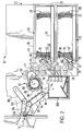
- Fig.2 is a side elevational view of a cash dispenser unit of the ATM of Fig. 1, the dispenser unit having two pick means, and parts of said unit being omitted;
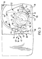
- Fig.3 is an enlarged side elevational view of one of the pick means of Fig.2; and
- Fig.4 is a block circuit diagram of the ATM of Fig. 1.
-
- With reference to Figs. 1 and 4 there is illustrated an ATM 2 in accordance with the present invention, which includes a control means in the form of a central processor unit (CPU) 4 which has stored therein a control program which controls the operation of the ATM 2 in dependence upon information gained from a plurality of sensors 110-120. If sensors are added or removed from the terminal 2 the program may be updated. The program monitors and optimises the operation of the ATM 2.
- The CPU 4 is connected to a
user interface device 6 incorporating a slot 8 (Fig. 1), connected to a conventional card reader 130 (Fig.4), for receiving a user identity card, akey pad 10 for inputting data, ascreen 12 for displaying user information, and anoutput slot 14 for dispensing bank notes to a user. The CPU 4 is also connected to a cash dispenser unit 16 (Fig.2) and a conventional printer 122 (Fig.4) for printing documents such as statements, receipts and account balances. - Referring particularly to Figs.2 and 3, the
cash dispenser unit 16 includes two similar pick means 18 arranged one above the other and respectively associated with twostorage cassettes 20 which are removably mounted in a supportingframework 22 of thedispenser unit 16. Each of thestorage cassettes 20 is arranged to contain a stack ofbank notes 24, corresponding long edges of which are supported on ahorizontal support plate 26 mounted in thestorage cassette 20. The stack ofnotes 24 in eachstorage cassette 20 is urged by a spring loadedpusher member 28 towards astop member 30 mounted at the front end of eachstorage cassette 20. Anopening 32 is formed in the front end of eachstorage cassette 20, the opening 32 being closed normally by conventional shutter means (not shown) when thestorage cassette 20 is not mounted in thedispenser unit 16. When astorage cassette 20 is mounted correctly in thedispenser unit 16, the shutter is automatically retracted to enablenotes 24 to be extracted through theopening 32 by the associated pick means 18. - Each pick means 18 includes a
tubular member 34 which extends between, and is rotatably mounted with respect to,side walls 36 and 38 (Fig.3) of theframework 22. Twoconventional pick arms 40, each incorporating arubber suction pad 42, are secured on eachtubular member 34, eachpick arm 40 communicating with the interior of the associatedtubular member 34. Corresponding ends of thetubular members 34 project beyond theside wall 38, and are each connected by a respectiveswivel elbow connector 44 to arespective rubber tube 46 via which reduced pressure is applied in operation to the respectivetubular member 34. The suction force produced by a suction pump 140 (Fig.4) is applied to a first note 24' in the stack ofnotes 24 in thestorage cassette 20 via thetubular members 34 andsuction pads 42, when thesuction pads 42 are in contact with the first note 24' and a solenoid valve 142 (Fig.4) located between thesuction pump 140 and thesuction pads 42 is opened. - A
gear segment 48 is secured to that part of eachtubular member 34 projecting beyond theside wall 38, thegear segment 48 being in co-operative engagement with atoothed end portion 50 of a first arm of a respectivebell crank lever 52 which is pivotably mounted on astud 54 secured to the outer surface of thewall 38. Eachlever 52 is urged to rotate in a counter clockwise direction with reference to Fig.3 by means of aspring 56 the ends of which are respectively attached to theside wall 38 and to the end of the second arm of thelever 52. Astud 58 is secured to one side of eachlever 52, thestud 58 engaging in acam track 60 formed in an associatedcam member 62. Eachcam member 62 is secured to arespective gear wheel 64 which is rotatably mounted on arespective shaft 66 projecting from the outer surface of theside wall 38. Thegear wheels 64 are driven bygear wheels 68 forming part of agear mechanism 69 operated by a main electric drive motor 70 (Fig.4). In operation, with thedrive motor 70 energised, thegear wheels 64 are rotated in a clockwise direction with reference to Fig. 3. This rotation of thegear wheels 64 brings about an oscillatory pivotal movement of thelevers 52 by virtue of the engagement of thestuds 58 in thecam tracks 60, thesprings 56 holding thestuds 58 in engagement with the inner edges of thecam tracks 60. By virtue of the engagement of thegear segments 44 with thetoothed portions 50 of thelevers 52, the oscillatory movement of thelevers 52 brings about an oscillatory pivotal movement of the assemblies of thetubular members 34 and the associatedpick arms 40. As will be explained in more detail later, the oscillatory movement of either of the assemblies of thetubular members 34 and the associatedpick arms 40 is effective to causenotes 24 to be picked one by one from the stack ofnotes 24 held in the associatedstorage cassette 20. - The ATM 2 incorporates a
motor sensor 110 which includes a timing disc 72 (Fig.3) secured to the face of eachgear wheel 64 remote from an associatedcam member 62. Thetiming disc 72 is for the most part transparent but incorporates an arcuateopaque strip 74 extending around just over half the periphery of thedisc 72. Eachtiming disc 72 is associated with optical sensing means, comprising an LED (not shown) and a co-operating photo-transistor sensor 113, which is arranged to sense theopaque strip 74. In operation, as each assembly of agear wheel 64 and the associatedcam member 62 andtiming disc 72 rotates in response to energization of thedrive motor 70, the associatedsensor 113 generates output signals in response to the sensing of the leading and trailing edges of the associatedopaque strip 74. It should be understood that the signals generated by each of thesensors 113 provide indications as to the precise positions of the associatedpick arms 40 at the times when these signals are generated. - As the
drive motor 70 is a variable speed motor then the speed of rotation of thedrive motor 70 can be varied in order to vary the time for which thepick arms 40 hold the associatedsuction pads 42 in contact with a first note 24' in the stack ofnotes 24 in one of thestorage cassettes 20, before attempting to pick the first note 24' from thestorage cassette 20. If thesolenoid valve 142 is opened just after thesuction pads 42 are brought into contact with the first note 24' then varying the period for which thesuction pads 42 are held in contact with the first note 24' will vary the suction force applied to the first note 24', as will be discussed in more detail below. - The suction force applied to the first note 24' prior to attempting to pick the first note 24' from the
storage cassette 20 can also be varied by varying the delay between operating thepump 140 and opening thesolenoid valve 142 to apply the suction force to the first note 24'. The longer the delay prior to opening thesolenoid valve 142 the larger the suction force produced by thesuction pump 140 will be. - Therefore, the suction force used in picking the first note 24' can be varied by varying either the speed of rotation of the
drive motor 70 or varying the delay prior to opening thesolenoid valve 142. - The
dispenser unit 16 also incorporatesfeed rollers 77 for feeding thebank notes 24 along afeed path 78 from each of thestorage cassettes 20 to astacking wheel 82 and on to theoutput slot 14, therollers 77 being associated with co-operating first andsecond rollers storage cassette 20. - In the course of a normal pick operation the lower long edge of the first bank note 24' of the stack of
notes 24 in a selected one of thestorage cassettes 20 is pulled partly out of thestorage cassette 20 under the suction force applied by therespective suction pads 42, and is fed between the associated first andsecond rollers rollers feed path 78 for feeding by therollers 77. - The stacking
wheel 82 is arranged to receivenotes 24 fed along thefeed path 78. The stackingwheel 82 serves to stacknotes 24 picked from one or both of thestorage cassettes 20 so as to form abundle 84 of notes for delivery to theoutput slot 14 for collection by the user. - The stacking
wheel 82 is driven by thedrive motor 70 and is arranged to rotate continuously in operation in a counter clockwise direction. Multiple note detection means 144 (Fig.4) are provided between theupper transport mechanism 85 and the stackingwheel 82 for detecting any multiple feeding of notes. The stackingplates 86 are spaced apart in parallel relationship along thestacker wheel shaft 88, each stackingplate 86 incorporating a series ofcurved tines 90. Thetines 90 of the stackingplates 86 pass between portions of a rockably mountedstripper plate assembly 94. In operation, each note fed along thefeed path 78 to the stackingwheel 82 enters betweenadjacent tines 90 and is carried partly around the axis of the stackingwheel 82, the note being stripped from thewheel 82 by the portions of thestripper plate assembly 94 and being stacked against belt means 95. The belt means 95 co-operates with belt means 98 normally held in the position shown in Fig.2. When the bundle of notes 84 (or possibly a single note only) to be dispensed to a user, in response to a cash withdrawal request, has been stacked against the belt means 95, the belt means 98 is rocked in a clockwise direction about ashaft 100 so as to trap thebundle 84 of notes between the belt means 95 and the belt means 98. It should be understood that in the course of this rocking movement separate belts making up the belt means 98 pass between adjacent pairs of the stackingplates 86. - Assuming that none of the
notes 24 in thebundle 84 have been rejected for any reason, the belt means 95 and 98 are operated so as to drive thebundle 84 to an adjacent pair of belt means 102 and 104. The belt means 102 and 104 serve to drive thebundle 84 through theoutput slot 14 to a position where thebundle 84 can be collected by the user of the ATM 2, ashutter 106, which serves to close theslot 14 when the ATM is note in operation, having previously been retracted to an open position. - It should be understood that the belt means 95 and 98 are mounted in resilient relationship relative to each other, and the belt means 102 and 104 are also mounted in resilient relationship relative to each other, so that bundles of notes of varying thickness can be held between, and fed by, the belt means 95 and 98 and the belt means 102 and 104.
- The belt means 95,98,102 and 104 are driven under the control of the CPU 4 by a
bi-directional stepping motor 71. - If a multiple feeding has been detected in the course of stacking the bundle of
notes 84 against the belt means 95, or if one or more of the notes in thebundle 84 have been rejected for any other reason, then thestripper plate assembly 94 is rocked into the position shown in chain outline in Fig.2, and the belt means 95 and 98 are operated to feed thebundle 84 in a direction opposite to the normal feed direction, thebundle 84 being deposited in apurge bin 108 via an opening in the top thereof. Also, if abundle 84 of notes or asingle note 24 is mis-aligned or becomes jammed between the stackingwheel 82 and theoutput slot 14 then the steppingmotor 71 can be operated so as to cause the belt means 95,98,102 and 104 to drive thenote 24 or bundle 84 of notes in the forward and the reverse direction repeatedly, in an attempt to unblock the currency jam or to realign thebank note 24 or bundle 84 of bank notes. - An ATM 2 in accordance with the present invention incorporates a plurality of sensors 110-120 (Fig.4) in communication with the CPU 4 arranged to monitor the operation of the ATM 2 and the ambient conditions. The CPU 4 is adapted to alter the operation of the ATM 2 in dependence on the output of the sensors 110-120 so as to reduce the number of malfunctions that occur in operation. The sensors 110-120 comprise: the
first motor sensor 110 located adjacent thedrive motor 70; asecond motor sensor 112 located adjacent the steppingmotor 71, thesecond motor sensor 112 including a photo-transistor sensor (not shown) arranged to detect the speed of the steppingmotor 71; apurge bin sensor 114 located adjacent the entrance to thepurge bin 108 and arranged to detect the deposition of asingle note 24 or abundle 84 of notes in thepurge bin 108; a plurality of optical banknote location sensors 116 located along thefeed path 78 and between the stackingwheel 82 and theoutput slot 14 and arranged to monitor at any instant the presence or absence ofnotes 24 at different locations within the ATM 2; a plurality oftemperature sensors 118 located within the ATM 2, providing the CPU 4 with an accurate measure of the temperatures at selected locations throughout the ATM 2; and a plurality ofhumidity sensors 120 also located within the ATM 2 so as to provide the CPU 4 with an accurate measure of the ambient humidity at selected locations throughout the ATM 2. - When the ATM 2 is operating, the sensors 110-120 continually monitor the operation of the ATM 2 and ambient conditions and communicate the information obtained to the CPU 4. For example, the
temperature sensors 118 may detect that the ambient temperature within the ATM 2 is lower than a predetermined temperature. On receipt of this information the CPU 4 will bring about one or more of a number of actions in order to reduce the likelihood of a malfunction occurring. Thus, for example, the CPU 4 may reduce the speed of thedrive motor 70 which drives therollers note 24 and therollers note 24 is being fed through thedispenser unit 16. As thedrive motor 70 also controls the positioning of thepick arms 40, reducing the speed of thedrive motor 70 will cause therubber suction pad 42 of thepick arms 40 to be held adjacent the first note 24' in the correspondingstorage cassette 20 for an increased period of time thereby increasing the suction force applied to the note 24'. The exact increase in time that therubber suction pads 42 are held in contact with the first note 24' prior to picking will depend on the ambient temperature detected by thetemperature sensors 118. - Alternatively, the CPU 4 may increase the suction force applied to the first note 24' by increasing the delay prior to opening the
solenoid valve 142 to apply the suction force to the first note 24', as discussed above. - The CPU 4 obtains temperature information from each of the
temperature sensors 118 which can be processed separately so that the CPU 4 can vary the operation of individual components of the ATM 2 dependent on their temperatures so as to optimize the operation of the ATM 2. For example, atemperature sensor 118 is located in each of thestorage cassettes 20 and at various locations throughout thefeed path 78. If thefirst storage cassette 20 is at a higher temperature than the second storage cassette 20 anote 24 will be picked from thesecond storage cassette 20 more slowly than from thefirst storage cassette 20 in order to compensate for the lower temperature in thesecond storage cassette 20. Also the speed of themotor 70 can be altered while anote 24 is being fed along thefeed path 78 in order to compensate for differences in ambient temperature detected by thetemperature sensors 118 located throughout the feed means 78. - The CPU 4 also monitors by means of the
sensor 114 the deposition of anote 24 or abundle 84 of notes in thepurge bin 108. If the CPU 4 finds that the rejection rate is tending to increase then the CPU 4 will cause the speed of thedrive motor 70 to be reduced, which action will normally be successful in reducing the rejection rate. Under the control of the control program stored therein, the CPU 4 maintains the time taken to dispense abundle 84 of notes as low as possible while limiting the number of times that notes 24 are rejected to a predetermined acceptable percentage of total pick operations. - A feature of the ATM 2 in accordance with the present invention is that the operating characteristics and ambient conditions of the ATM 2 are monitored and its operation is altered in dependence thereon in order to optimise its operation.
- The ATM 2 is also arranged to attempt to rectify malfunctions, such as currency jams, which would normally require the intervention of an operator. For example, if a jam has occurred, depending on where the jam has occurred, the CPU 4 may cause different actions to be carried out in order to attempt to clear the jam. If the jam is located between the stacking
wheel 82 and theoutput slot 14 the steppingmotor 71 can be caused to follow a particular routine likely to succeed in freeing the jam, which may involve driving the belt means 94,95 ,102 and 104 at different speeds and in the forward and reverse direction. However, if the jam is located between one of thestorage cassettes 20 and the stackingwheel 82 no action can be taken to unblock the jam as thedrive motor 70 is a unidirectional motor and consequently the feed means 77,79 and 80 can only be driven in one direction with respect to thefeed path 78. In this case an error message is produced by the CPU 4 to inform the operator of the location of the currency jam. - Other parameters and errors may be detected by the sensors 110-120 and the above examples are presented in order to illustrate the operation of an ATM 2 in accordance with the present invention. For example, the ambient humidity, which may affect the suction force required to pick
notes 24 from the stack ofnotes 24 in the selectedstorage cassette 20, is monitored throughhumidity sensors 120 and the ATM operation is altered as necessary in order to compensate for variations in humidity. - As with ambient temperature, humidity affects the ability of the suction means 42 to pick notes 24. If the ambient humidity is low so that the
notes 24 are dry thesuction pads 42 will be able to separate the first note 24' from the remainingnotes 24 in thestorage cassette 20 relatively easily. However, if humidity is high, thenotes 24 may become moist and each may tend to stick to theadjacent note 24. Therefore, if humidity is high, the pick means 18 will require a greater suction force to picknotes 24 from thestorage cassettes 20. Therefore, with high humidity, thesuction pads 42 may be held in contact with the first note 24' for a longer period of time than would be the case for a low ambient humidity. - When designing an ATM 2 in accordance with the present invention an engineer will in parallel create a plurality of computer models of acceptable ATM operation. Each of the models will relate to a specific ATM function and will comprise "objects" which define the component parts of the ATM 2 and "tasks" which define the function to be carried out by each component i.e. the range of times for which the
suction pads 42 can be held in contact with a first note 24' to pick the note 24' from thestorage cassette 20. - Thus the objects and their associated tasks model predetermined acceptable operation of the ATM 2, when in use.
- The sensors 110-120 transmit their data to a
task processor 124, within the CPU 4, through an input/output (I/O)card 126 which incorporates a plurality of individual ports (not shown) assigned to each of the sensors 110-120. Additional ports on the I/O card 126 are each assigned to individual components of the ATM 2, through which the CPU 4 controls the operation of the ATM 2. The CPU 4 further includes a "rule base" which is stored in afirst memory 136 and which is accessed when the sensors 110-116 detect a trend away from the predetermined acceptable operation of the ATM 2. The rule base defines a set of sequential steps which can be taken by thetask processor 124 to determine why said trend has arisen and how, if possible, the condition which caused the trend can be rectified. For example, thetask processor 124 may, in accordance with the rule base, determine that there has been a change in ambient temperature through thetemperature sensors 118. The rule base may then instruct thetask processor 124 to alter the speed of rotation of themotor 70 and/or themotor 71 in an attempt to alleviate the problem. - When the ATM 2 is activated for use, the first of the plurality of computer models is loaded into the
task processor 124 from a second memory 138 (Fig.4) and becomes operational. The initial model which is loaded into thetask processor 124 is a card reader model which models predetermined acceptable operation of the card reader 130 (Fig.4). The model is loaded automatically when a card is input into the card slot 8 (Fig. 1) in the ATM 2. The model includes a list of initial and final settings for, and details of acceptable operation of, components of thereader 130 including: a card transport means; a transport means motor; and a reader head, as well as details of the time for which the motor must operate to pass the card under the reader head so as to read data from the card. Also, as the card is normally stored in thecard reader 130 until the ATM transaction is complete, the model also includes the instruction required from the ATM 2 to cause the reader to present the card to the user. - Once the user has gained access to the ATM 2 and prior to the initial service being requested by the user, an initialisation model is loaded into the
task processor 124. The initialisation model includes initial settings for the movable components of the ATM 2 including themain drive motor 70, the steppingmotor 71, the pick means 18, thestripper plate assembly 94 and the pivotably mounted belt means 98. When the initialisation model is loaded into thetask processor 124, thetask processor 124 causes each of these components or objects to become operational and to move, in their normal manner, until sensors associated with one or more of the components detect movement of the components and send signals to thetask processor 124, through the I/O card 126, thus confirming that the each of the sensors is operating correctly. Thetask processor 124 then instructs each of these components to move to their initial operating position, which is confirmed by the associated sensors. The ATM 2 is then ready to act upon a service request from the user. - Assuming the user requests the withdrawal of currency from the ATM 2, then the appropriate currency withdrawal model will be loaded into the
task processor 124. There are two currency withdrawal models, a first model which models acceptable ATM operation when picking a note from thefirst storage cassette 20 and a second model which models acceptable ATM operation when picking a note from thesecond storage cassette 20. - A request for an amount of currency to be dispensed will be processed by the
task processor 124 into a combination of dispensing actions, picking notes from one or other of thestorage cassettes 20 dependent on the amount of currency requested and the quantity and denominations of the notes in each of thestorage cassettes 20. For example, if thefirst storage cassette 20 contains £10 notes and thesecond storage cassette 20 contains £20 notes, a request for the withdrawal of £40 can be completed by picking two £20 notes or four £10 notes or one £20 note and two £10 notes. Depending on the quantity of notes in each of thestorage cassettes 20 thetask processor 124 will make a determination as to which of the above combinations of notes will be dispensed, and will instruct the pick means 18 to pick the appropriate number of notes from one or both of thestorage cassettes 20. Each time anote 24 is picked from the first orsecond storage cassette 20, the appropriate first or second currency withdrawal model will be run in thetask processor 124 and the actual operation of the ATM 2, determined by the sensors 110-116, will be compared with predetermined acceptable ATM operation as defined by the model. For example, if the sum is to be made up of four £10 notes taken from thefirst storage cassette 20, then the first currency withdrawal model will be run in thetask processor 124 four times, i.e. each time anote 24 is picked, and the actual picking operation will be compared in thetask processor 124 with the predetermined acceptable operation, as defined in the model. - The models can best be explained by considering the passage of a
note 24 through the ATM 2. The currency withdrawal models commence with the movable components of the ATM 2 in their initial positions, as the initialisation model will have been run prior to the request for a cash withdrawal. The models each state the range of acceptable times for which thesuction pads 42 can be held in contact with the note 24' as a vacuum force is built up to pick the note 24' from the associatedstorage cassette 20, as discussed above. The actual time thesuction pads 42 are held against the note 24' will be determined by thetask processor 124 dependent on information from the sensors 110-120, as discussed above, thus the time may be longer if slippage ofnotes 24 or multiple feeds have been detected due to wear of components or low ambient temperature. The model also includes a time table for the passage of each of the picked notes 24 through sections of thefeed path 78 to the stackingwheel 82 and on to the dispenseslot 14, each section containing a banknote location sensor 116, the passage of each of the notes being detected by the plurality of banknote location sensors 116. Again the time taken for the passage of anote 24 is compared in thetask processor 124 with the predetermined acceptable time included in the model. Again if the time taken for each of thenotes 24 to pass from one section to the next tends towards the minimum or maximum allowed time, according to the model, thetask processor 124 alters the speed of rotation of one or both of themotors notes 24 occurs the motor speed is altered in an attempt to alleviate the problem. - Individual notes 24 are fed into the stacking
wheel 82 forming abundle 84 of notes prior to being presented to the user through theoutput slot 14 by the belt means 95,98,102 and 104, after being stripped from the stackingwheel 82 by thestripper plate assembly 94. Therefore, the model also includes a range of acceptable rotational speeds for the steppingmotor 71. - Thus the entire passage of
notes 24 from either of thestorage cassettes 20 to the dispenseslot 14 is modelled by the currency withdrawal model. - Once a
note 24 or bundle 84 ofnotes 24 have been successfully dispensed to the user and the user has removed thenotes 24 and the user identity card, the card reading model and first currency withdrawal model are down loaded by thetask processor 124 to thememory 136 and thetask processor 124 awaits the insertion of the next user identification card by the next user of the ATM 2. - There are also additional models which model predetermined acceptable operation of other components of the ATM 2 such as the printer 122 (Fig.4).
- When the ATM 2 is in use, information regarding the success or failure of a pick operation will be forwarded to the
task processor 124 from the purge bin sensor 114 (Fig.4). This information will be added to the information relating to pick success already stored in thetask processor 124. If the most recent result tend towards the boundaries of the predetermined acceptable range then thetask processor 124 will activate the rule base, from thefirst memory 136 in the CPU 4, to determine the probable cause of the increase in the number of mis-picks. For example, ambient conditions will be monitored to see if the temperature has fallen or risen. If the temperature has fallen the rule base states that the number of mis-picks may be reduced by increasing the dispense time as described above. Therefore, the rule base may suggest that the variation between the desired operation of the ATM 2 as defined by the currency withdrawal model (ratio of unsuccessful pick operations to successful pick operations being less than a predetermined maximum) and the actual operation of the ATM 2 as detected by thesensor 114 may be overcome by increasing dispense time by reducing the speed of rotation of thedrive motor 70. The speed of rotation of themotor 70 may be decreased incrementally as each successive request for currency from the ATM 2 is processed until the ratio of unsuccessful pick operations to successful pick operations is once again well below the predetermined maximum, while maintaining as low as possible a dispense time. - Ambient temperature and ATM operation can continue to be monitored and ATM operation altered in dependence on fluctuations in ambient temperature. A table of optimum dispense times for given temperatures can also be stored in the
task processor 124 so that the speed of rotation of the motor 70 (and possibly also that of the motor 71) can be set so as to optimise ATM operation. - The rule base may also be utilised when a currency jam is detected and the ATM 2 fails to dispense currency successfully. The rule base will instruct the
task processor 124 to enter an "unblocking" program, in which the steppingmotor 71 may be instructed to run at different speeds and sequentially in forward and reverse direction, as discussed above. - In conclusion, an ATM 2 in accordance with the present invention can alter its operation in dependence upon information provided by a plurality of sensors 110-120 positioned throughout the ATM 2.
Claims (9)
- A transaction terminal (2) including control means (4) for controlling the operation of said terminal (2), and a plurality of ambient environmental condition sensors (118-120) in communication with said control means (4), characterized in that the terminal (2) further comprises a plurality of sensors (110-116) for monitoring the operating characteristics of said terminal (2), and said control means (4) has stored therein data characteristic of predetermined acceptable terminal operation, and is arranged to compare the outputs of said sensors (110-116) with said data, said control means (4) being arranged to alter terminal operation in response to said outputs in order to maintain said acceptable terminal operation.
- A terminal according to claim 1, characterized by currency dispense means (16) arranged to pick bank notes from bank note storage means (20) and to dispense picked bank notes to a user of the terminal (2), said sensors (110-116) including a sensor (114) which detects the deposition of a bank note (24) or a bundle of bank notes (84) in a purge bin (108), due to a malfunction during a currency dispense transaction, and which transmits a signal to said control means (4) each time a bank note (24) or bundle (84) of bank notes is deposited in said purge bin (108).
- A terminal according to claim 2, characterized in that said control means (4) controls the speed of operation of feed means (77,78,79) utilised in transporting bank notes (24) to be dispensed to a user, said control means (4) being arranged to maintain a predetermined acceptably short dispense time while maintaining the ratio of unsuccessful pick operations to successful pick operations below a predetermined maximum.
- A terminal according to either claim 2 or claim 3, characterized in that said currency dispense means (16) includes suction means (18) for picking bank notes (24) from said storage means (20), said control means (4) being arranged to alter the suction force applied to a bank note (24) to be picked from said storage means (20).
- A terminal according to claim 4, characterized in that said control means (4) is arranged to alter said suction force by altering the time for which said suction means (18) is in contact with a bank note (24) to be picked.
- A terminal according to claim 4, characterized in that said control means (4) is arranged to alter said suction force by altering the delay between operating a suction pump (140) which generates said suction force and opening a valve (142) which connects said suction pump (140) to said suction means (18).
- A terminal according to any one of claims 2 to 6, characterized in that said sensors (110-116) include bank note location sensor means (116) arranged to detect when a bank note jam has occurred within said terminal (2), said control means (4) being responsive to outputs of said bank note location sensor means (116) to reverse the operation of a motor (71) for driving feed means (102,104) where a jam has occurred in an attempt to free the jam.
- A terminal according to any preceding claim, characterized in that said control means (4) is arranged to alter terminal operation in response to outputs of said ambient environmental condition sensors (118-120).
- A terminal according to any preceding claim, characterized in that said control means (4) has stored therein a plurality of models each of which contains data characteristic of predetermined acceptable terminal operation for a function provided by said terminal (2), said control means (4) being arranged to load a model corresponding to a particular function into a task processor (124) for use, when said function is to be performed by said terminal (2).
Applications Claiming Priority (2)
| Application Number | Priority Date | Filing Date | Title |
|---|---|---|---|
| GB9426341 | 1994-12-29 | ||
| GBGB9426341.5A GB9426341D0 (en) | 1994-12-29 | 1994-12-29 | A transaction terminal |
Publications (3)
| Publication Number | Publication Date |
|---|---|
| EP0720132A2 EP0720132A2 (en) | 1996-07-03 |
| EP0720132A3 EP0720132A3 (en) | 1996-08-28 |
| EP0720132B1 true EP0720132B1 (en) | 1999-07-14 |
Family
ID=10766676
Family Applications (1)
| Application Number | Title | Priority Date | Filing Date |
|---|---|---|---|
| EP95309413A Expired - Lifetime EP0720132B1 (en) | 1994-12-29 | 1995-12-22 | A transaction terminal |
Country Status (7)
| Country | Link |
|---|---|
| US (1) | US5719383A (en) |
| EP (1) | EP0720132B1 (en) |
| JP (1) | JP3816561B2 (en) |
| DE (1) | DE69510761T2 (en) |
| ES (1) | ES2136257T3 (en) |
| GB (1) | GB9426341D0 (en) |
| ZA (1) | ZA9510988B (en) |
Cited By (2)
| Publication number | Priority date | Publication date | Assignee | Title |
|---|---|---|---|---|
| US7946576B2 (en) | 2004-02-23 | 2011-05-24 | Mei, Inc. | Document stacker with fault detection |
| US8186672B2 (en) | 2006-05-22 | 2012-05-29 | Mei, Inc. | Currency cassette capacity monitoring and reporting |
Families Citing this family (39)
| Publication number | Priority date | Publication date | Assignee | Title |
|---|---|---|---|---|
| US6264101B1 (en) * | 1997-11-28 | 2001-07-24 | Diebold, Incorporated | Control system for currency recycling automated banking machine |
| US6607081B2 (en) * | 1996-11-15 | 2003-08-19 | Diebold, Incorporated | Automated transaction machine system |
| JP3909115B2 (en) * | 1997-06-09 | 2007-04-25 | 株式会社日立製作所 | Apparatus information acquisition apparatus and apparatus apparatus information collection method |
| AU8899398A (en) * | 1997-08-13 | 1999-03-08 | Citicorp Development Center, Inc. | Personal banking machine |
| US6082616A (en) * | 1998-06-02 | 2000-07-04 | Diebold, Incorporated | Automated banking machine enclosure |
| US6845907B1 (en) * | 1998-11-13 | 2005-01-25 | Diebold, Incorporated | Cash delivery apparatus for motor fuel dispenser or other self service facility |
| JP3952635B2 (en) * | 1999-06-01 | 2007-08-01 | 富士通株式会社 | Automatic transaction equipment |
| GB2353388B (en) * | 1999-08-19 | 2003-10-15 | Ncr Int Inc | Media processing |
| SE518965C2 (en) * | 1999-11-04 | 2002-12-10 | Ruben Haegglund | Currency Management Device |
| US6443359B1 (en) * | 1999-12-03 | 2002-09-03 | Diebold, Incorporated | Automated transaction system and method |
| JP2001256532A (en) * | 2000-03-14 | 2001-09-21 | Fujitsu Ltd | Medium issue device using paper roll medium and automatic transaction machine using this device |
| GB2364591A (en) * | 2000-07-07 | 2002-01-30 | Ncr Int Inc | Self service terminal with an escrow unit |
| EP1220167A1 (en) * | 2000-12-28 | 2002-07-03 | Mars Inc. | Banknote store |
| JP3999476B2 (en) * | 2001-06-21 | 2007-10-31 | 日立オムロンターミナルソリューションズ株式会社 | Banknote handling equipment |
| US6945456B2 (en) * | 2002-11-25 | 2005-09-20 | Diebold Self-Service Systems A Division Of Diebold, Incorporated | Automated banking machine including temperature controlled housing |
| US8100323B1 (en) | 2002-12-26 | 2012-01-24 | Diebold Self-Service Systems Division Of Diebold, Incorporated | Apparatus and method for verifying components of an ATM |
| US7780073B2 (en) * | 2002-12-31 | 2010-08-24 | Diebold Self-Service Systems, Division Of Diebold, Incorporated | Polymer divert cassette for ATM currency |
| CN101866512B (en) * | 2002-12-31 | 2011-09-14 | 迪布尔特有限公司 | ATM currency cassette arrangement and its operation method |
| US7044366B2 (en) * | 2003-03-10 | 2006-05-16 | Diebold Self-Service Systems Division Of Diebold, Incorporated | Cash dispensing automated banking machine deposit accepting system and method |
| US20040178559A1 (en) * | 2003-03-10 | 2004-09-16 | Diebold Self-Service Systems Division Of Diebold, Incorporated | Picker shaft arrangement for ATM currency dispenser |
| SE527837C2 (en) * | 2004-01-08 | 2006-06-20 | Unjo Ab | Control system for banknotes handlers |
| JP4076165B2 (en) | 2004-02-05 | 2008-04-16 | インターナショナル・ビジネス・マシーンズ・コーポレーション | Management device, storage cassette, automatic teller machine, information processing system, management method, and control method |
| US7513416B1 (en) * | 2004-07-29 | 2009-04-07 | Diebold Self-Service Systems | Cash dispensing automated banking machine deposit printing system and method |
| JP4622377B2 (en) * | 2004-08-10 | 2011-02-02 | 沖電気工業株式会社 | Banknote deposit and withdrawal machine |
| CH695124A5 (en) * | 2004-12-10 | 2005-12-15 | Wincor Nixdorf Ag | Control system for automatic teller machine (ATM), includes control unit that regulates operation of memory of ATM based on stored software, and evaluates transaction data stored in memory using logical control system |
| GB0427693D0 (en) * | 2004-12-17 | 2005-01-19 | Ncr Int Inc | An automated teller machine |
| GB0427694D0 (en) * | 2004-12-17 | 2005-01-19 | Ncr Int Inc | A method of determining the cause of an error state in an apparatus |
| KR101001690B1 (en) * | 2004-12-30 | 2010-12-28 | 노틸러스효성 주식회사 | Bill recycling machine |
| JP4942330B2 (en) * | 2005-11-21 | 2012-05-30 | 日立オムロンターミナルソリューションズ株式会社 | Paper sheet handling equipment |
| US20070138733A1 (en) * | 2005-12-16 | 2007-06-21 | Chris Gray | Pick mechanism |
| US7641185B2 (en) * | 2005-12-22 | 2010-01-05 | Ncr Corporation | Vacuum pick mechanisms |
| US7789299B1 (en) * | 2006-03-15 | 2010-09-07 | Diebold Self-Service Systems, Division Of Diebold, Incorporated | Automated banking machine that allows servicer to use customer display to view images from a camera located inside the machine |
| US20100082494A1 (en) * | 2008-09-29 | 2010-04-01 | Infosys Technologies Limited | Method and system for cash transfer |
| US20100131374A1 (en) * | 2008-11-25 | 2010-05-27 | Bank Of America Corporation | Integrated Currency Scales |
| US8157078B1 (en) * | 2008-11-25 | 2012-04-17 | Bank Of America Corporation | Cash handling device having environmental condition monitoring system |
| US8608056B2 (en) * | 2011-12-20 | 2013-12-17 | Ncr Corporation | Guiding pathway |
| JP5900251B2 (en) * | 2012-09-03 | 2016-04-06 | 沖電気工業株式会社 | Banknote handling equipment |
| US10467842B2 (en) | 2017-03-17 | 2019-11-05 | Bank Of America Corporation | Portable item transfer container |
| JP7362654B2 (en) * | 2018-04-27 | 2023-10-17 | エヌチェーン ライセンシング アーゲー | Maintenance and management of blockchain blocks in a divided blockchain network |
Family Cites Families (26)
| Publication number | Priority date | Publication date | Assignee | Title |
|---|---|---|---|---|
| US3937925A (en) * | 1974-06-25 | 1976-02-10 | Ibm Corporation | Modular transaction terminal with microprocessor control |
| US4589712A (en) * | 1977-08-25 | 1986-05-20 | Hastings Otis | Data processing equipment enclosures |
| US4377847A (en) * | 1981-02-17 | 1983-03-22 | Gould Inc. | Microprocessor controlled micro-stepping chart drive |
| US4413738A (en) * | 1981-03-11 | 1983-11-08 | Owens-Illinois, Inc. | Apparatus and method for controlling the inspection of finished products |
| US4544149A (en) * | 1982-02-04 | 1985-10-01 | Diebold, Incorporated | Multi-picker mechanism for automatic banking machines |
| JPS59184989A (en) * | 1983-04-04 | 1984-10-20 | 株式会社東芝 | Segmental integrator |
| US4660168A (en) * | 1984-03-14 | 1987-04-21 | Grant Elwyn E | Apparatus for completing a customer initiated ATM transaction |
| JPS61208516A (en) * | 1985-03-13 | 1986-09-16 | Toshiba Corp | Supervisory unit |
| JPS61276089A (en) * | 1985-05-31 | 1986-12-06 | 株式会社東芝 | Paper money transport controller |
| DE3639755A1 (en) * | 1985-11-22 | 1987-05-27 | Oki Electric Ind Co Ltd | SELF-DIAGNOSIS METHOD FOR A DEVICE |
| US4928230A (en) * | 1987-03-23 | 1990-05-22 | Kabushiki Kaisha Toshiba | Automatic transacting apparatus |
| EP0288300B1 (en) * | 1987-04-23 | 1993-05-26 | Oki Electric Industry Co. Ltd. | Ticket processing terminal device |
| US5019249A (en) * | 1987-09-18 | 1991-05-28 | Hitachi, Ltd. | Apparatus for handling sheets of paper |
| US4813475A (en) * | 1988-03-07 | 1989-03-21 | Couvrette Edward F | Temperature control means for a self service banking system |
| US4885676A (en) * | 1988-03-09 | 1989-12-05 | Storage Technology Corporation | Control loop instability detection and correction apparatus |
| JP2754745B2 (en) * | 1989-06-15 | 1998-05-20 | 株式会社日立製作所 | Remote maintenance system for automatic teller machine |
| JP2854611B2 (en) * | 1989-07-07 | 1999-02-03 | キヤノン株式会社 | Image forming device |
| JPH0378082A (en) * | 1989-08-21 | 1991-04-03 | Hitachi Ltd | Reservation transaction processing method |
| JP2641595B2 (en) * | 1990-05-07 | 1997-08-13 | 富士写真フイルム株式会社 | Sheet-fed sheet method |
| CA2073899A1 (en) * | 1991-07-19 | 1993-01-20 | Tatsuya Hashinaga | Burn-in apparatus and method |
| GB2261304B (en) * | 1991-11-11 | 1994-11-16 | Daewoo Electronics Co Ltd | Apparatus and method for controlling the rotational speed of a motor |
| GB2269205B (en) * | 1992-07-08 | 1996-03-20 | P A Terry | Improvements in or relating to the security of paper items |
| US5452962A (en) * | 1993-01-28 | 1995-09-26 | Stop Stick, Inc. | Apparatus for deflating tires of moving vehicles |
| JPH0737138A (en) * | 1993-07-16 | 1995-02-07 | Toshiba Corp | Money processor |
| GB9320072D0 (en) * | 1993-09-29 | 1993-11-17 | Ncr Int Inc | Self-service system having predictive capability |
| GB9323489D0 (en) * | 1993-11-08 | 1994-01-05 | Ncr Int Inc | Self-service business system |
-
1994
- 1994-12-29 GB GBGB9426341.5A patent/GB9426341D0/en active Pending
-
1995
- 1995-12-22 EP EP95309413A patent/EP0720132B1/en not_active Expired - Lifetime
- 1995-12-22 ES ES95309413T patent/ES2136257T3/en not_active Expired - Lifetime
- 1995-12-22 DE DE69510761T patent/DE69510761T2/en not_active Expired - Fee Related
- 1995-12-27 ZA ZA9510988A patent/ZA9510988B/en unknown
- 1995-12-28 JP JP34277595A patent/JP3816561B2/en not_active Expired - Fee Related
-
1996
- 1996-12-22 US US08/754,333 patent/US5719383A/en not_active Expired - Lifetime
Cited By (2)
| Publication number | Priority date | Publication date | Assignee | Title |
|---|---|---|---|---|
| US7946576B2 (en) | 2004-02-23 | 2011-05-24 | Mei, Inc. | Document stacker with fault detection |
| US8186672B2 (en) | 2006-05-22 | 2012-05-29 | Mei, Inc. | Currency cassette capacity monitoring and reporting |
Also Published As
| Publication number | Publication date |
|---|---|
| JP3816561B2 (en) | 2006-08-30 |
| GB9426341D0 (en) | 1995-03-01 |
| JPH08263725A (en) | 1996-10-11 |
| ZA9510988B (en) | 1996-06-25 |
| US5719383A (en) | 1998-02-17 |
| DE69510761D1 (en) | 1999-08-26 |
| ES2136257T3 (en) | 1999-11-16 |
| EP0720132A3 (en) | 1996-08-28 |
| DE69510761T2 (en) | 1999-12-23 |
| EP0720132A2 (en) | 1996-07-03 |
Similar Documents
| Publication | Publication Date | Title |
|---|---|---|
| EP0720132B1 (en) | A transaction terminal | |
| US4521008A (en) | Fail safe document dispensing system | |
| US7815103B2 (en) | Method of and system for prediction of the state of health of an apparatus | |
| US5295675A (en) | Sheet handling apparatus having controlled pressure rolls to ensure feeding of a single sheet | |
| US5597996A (en) | Cash dispensing apparatus (ATM) and method for separating rejected bank notes | |
| GB2124005A (en) | Automatic bank note transaction apparatus | |
| EP3485469B1 (en) | Contact stripper/feed wheel implementation | |
| EP3485467B1 (en) | A center de-skew subassembly to center align documents | |
| US5110105A (en) | Sheet handling apparatus | |
| EP0448385B1 (en) | Sheet handling apparatus | |
| JP3865171B2 (en) | Banknote handling equipment | |
| JPH11339100A (en) | Paper money storage device | |
| CA2046568A1 (en) | Torque limiting mechanism for use in a drive system | |
| US20070139524A1 (en) | Method of determining the cause of an error state in an apparatus | |
| JP2000132728A (en) | Paper money storing device | |
| JPH06162324A (en) | Paper money paying and receiving device | |
| JP3822036B2 (en) | Medium transport device | |
| JP2000067302A (en) | Bill storing device | |
| JPH1063921A (en) | Processing terminal and bank note control method | |
| EP3484714A1 (en) | Dual side printing with one print head | |
| JP2000048242A (en) | Paper money storage device | |
| JPH11316863A (en) | Paper money storage device | |
| JPH11328489A (en) | Paper money housing device | |
| JPH11328477A (en) | Device for housing paper money | |
| JPH11353530A (en) | Paper money housing device |
Legal Events
| Date | Code | Title | Description |
|---|---|---|---|
| PUAI | Public reference made under article 153(3) epc to a published international application that has entered the european phase |
Free format text: ORIGINAL CODE: 0009012 |
|
| AK | Designated contracting states |
Kind code of ref document: A2 Designated state(s): DE ES FR GB IT |
|
| PUAL | Search report despatched |
Free format text: ORIGINAL CODE: 0009013 |
|
| AK | Designated contracting states |
Kind code of ref document: A3 Designated state(s): DE ES FR GB IT |
|
| 17P | Request for examination filed |
Effective date: 19970228 |
|
| 17Q | First examination report despatched |
Effective date: 19980504 |
|
| GRAG | Despatch of communication of intention to grant |
Free format text: ORIGINAL CODE: EPIDOS AGRA |
|
| GRAG | Despatch of communication of intention to grant |
Free format text: ORIGINAL CODE: EPIDOS AGRA |
|
| GRAH | Despatch of communication of intention to grant a patent |
Free format text: ORIGINAL CODE: EPIDOS IGRA |
|
| GRAH | Despatch of communication of intention to grant a patent |
Free format text: ORIGINAL CODE: EPIDOS IGRA |
|
| GRAA | (expected) grant |
Free format text: ORIGINAL CODE: 0009210 |
|
| AK | Designated contracting states |
Kind code of ref document: B1 Designated state(s): DE ES FR GB IT |
|
| REF | Corresponds to: |
Ref document number: 69510761 Country of ref document: DE Date of ref document: 19990826 |
|
| ITF | It: translation for a ep patent filed | ||
| ET | Fr: translation filed | ||
| REG | Reference to a national code |
Ref country code: ES Ref legal event code: FG2A Ref document number: 2136257 Country of ref document: ES Kind code of ref document: T3 |
|
| PLBE | No opposition filed within time limit |
Free format text: ORIGINAL CODE: 0009261 |
|
| STAA | Information on the status of an ep patent application or granted ep patent |
Free format text: STATUS: NO OPPOSITION FILED WITHIN TIME LIMIT |
|
| 26N | No opposition filed | ||
| REG | Reference to a national code |
Ref country code: GB Ref legal event code: IF02 |
|
| PGFP | Annual fee paid to national office [announced via postgrant information from national office to epo] |
Ref country code: ES Payment date: 20081029 Year of fee payment: 14 |
|
| PGFP | Annual fee paid to national office [announced via postgrant information from national office to epo] |
Ref country code: IT Payment date: 20081013 Year of fee payment: 14 |
|
| PGFP | Annual fee paid to national office [announced via postgrant information from national office to epo] |
Ref country code: FR Payment date: 20081007 Year of fee payment: 14 |
|
| PGFP | Annual fee paid to national office [announced via postgrant information from national office to epo] |
Ref country code: DE Payment date: 20081117 Year of fee payment: 14 |
|
| PGFP | Annual fee paid to national office [announced via postgrant information from national office to epo] |
Ref country code: GB Payment date: 20081009 Year of fee payment: 14 |
|
| GBPC | Gb: european patent ceased through non-payment of renewal fee |
Effective date: 20091222 |
|
| REG | Reference to a national code |
Ref country code: FR Ref legal event code: ST Effective date: 20100831 |
|
| PG25 | Lapsed in a contracting state [announced via postgrant information from national office to epo] |
Ref country code: FR Free format text: LAPSE BECAUSE OF NON-PAYMENT OF DUE FEES Effective date: 20091231 |
|
| PG25 | Lapsed in a contracting state [announced via postgrant information from national office to epo] |
Ref country code: DE Free format text: LAPSE BECAUSE OF NON-PAYMENT OF DUE FEES Effective date: 20100701 |
|
| PG25 | Lapsed in a contracting state [announced via postgrant information from national office to epo] |
Ref country code: GB Free format text: LAPSE BECAUSE OF NON-PAYMENT OF DUE FEES Effective date: 20091222 |
|
| REG | Reference to a national code |
Ref country code: ES Ref legal event code: FD2A Effective date: 20110301 |
|
| PG25 | Lapsed in a contracting state [announced via postgrant information from national office to epo] |
Ref country code: IT Free format text: LAPSE BECAUSE OF NON-PAYMENT OF DUE FEES Effective date: 20091222 |
|
| PG25 | Lapsed in a contracting state [announced via postgrant information from national office to epo] |
Ref country code: ES Free format text: LAPSE BECAUSE OF NON-PAYMENT OF DUE FEES Effective date: 20110228 |
|
| PG25 | Lapsed in a contracting state [announced via postgrant information from national office to epo] |
Ref country code: ES Free format text: LAPSE BECAUSE OF NON-PAYMENT OF DUE FEES Effective date: 20091223 |