EP0719571A2 - Medical apparatus - Google Patents
Medical apparatus Download PDFInfo
- Publication number
- EP0719571A2 EP0719571A2 EP95120604A EP95120604A EP0719571A2 EP 0719571 A2 EP0719571 A2 EP 0719571A2 EP 95120604 A EP95120604 A EP 95120604A EP 95120604 A EP95120604 A EP 95120604A EP 0719571 A2 EP0719571 A2 EP 0719571A2
- Authority
- EP
- European Patent Office
- Prior art keywords
- applicator
- thermotherapeutic
- shaft
- radiation source
- radiation
- Prior art date
- Legal status (The legal status is an assumption and is not a legal conclusion. Google has not performed a legal analysis and makes no representation as to the accuracy of the status listed.)
- Granted
Links
- 0 CC*1CC(*)(CC)CC(CC*(CCCC(*)CCCCCC[N+]([O-])=O)=CC)C1 Chemical compound CC*1CC(*)(CC)CC(CC*(CCCC(*)CCCCCC[N+]([O-])=O)=CC)C1 0.000 description 1
Images


Classifications
-
- A—HUMAN NECESSITIES
- A61—MEDICAL OR VETERINARY SCIENCE; HYGIENE
- A61N—ELECTROTHERAPY; MAGNETOTHERAPY; RADIATION THERAPY; ULTRASOUND THERAPY
- A61N5/00—Radiation therapy
- A61N5/10—X-ray therapy; Gamma-ray therapy; Particle-irradiation therapy
- A61N5/1001—X-ray therapy; Gamma-ray therapy; Particle-irradiation therapy using radiation sources introduced into or applied onto the body; brachytherapy
- A61N5/1014—Intracavitary radiation therapy
-
- A—HUMAN NECESSITIES
- A61—MEDICAL OR VETERINARY SCIENCE; HYGIENE
- A61N—ELECTROTHERAPY; MAGNETOTHERAPY; RADIATION THERAPY; ULTRASOUND THERAPY
- A61N1/00—Electrotherapy; Circuits therefor
- A61N1/40—Applying electric fields by inductive or capacitive coupling ; Applying radio-frequency signals
- A61N1/403—Applying electric fields by inductive or capacitive coupling ; Applying radio-frequency signals for thermotherapy, e.g. hyperthermia
-
- A—HUMAN NECESSITIES
- A61—MEDICAL OR VETERINARY SCIENCE; HYGIENE
- A61N—ELECTROTHERAPY; MAGNETOTHERAPY; RADIATION THERAPY; ULTRASOUND THERAPY
- A61N5/00—Radiation therapy
- A61N5/10—X-ray therapy; Gamma-ray therapy; Particle-irradiation therapy
- A61N5/1001—X-ray therapy; Gamma-ray therapy; Particle-irradiation therapy using radiation sources introduced into or applied onto the body; brachytherapy
- A61N5/1007—Arrangements or means for the introduction of sources into the body
- A61N2005/1012—Templates or grids for guiding the introduction of sources
-
- A—HUMAN NECESSITIES
- A61—MEDICAL OR VETERINARY SCIENCE; HYGIENE
- A61N—ELECTROTHERAPY; MAGNETOTHERAPY; RADIATION THERAPY; ULTRASOUND THERAPY
- A61N5/00—Radiation therapy
- A61N5/10—X-ray therapy; Gamma-ray therapy; Particle-irradiation therapy
- A61N5/1001—X-ray therapy; Gamma-ray therapy; Particle-irradiation therapy using radiation sources introduced into or applied onto the body; brachytherapy
- A61N5/1014—Intracavitary radiation therapy
- A61N2005/1018—Intracavitary radiation therapy with multiple channels for guiding radioactive sources
-
- A—HUMAN NECESSITIES
- A61—MEDICAL OR VETERINARY SCIENCE; HYGIENE
- A61N—ELECTROTHERAPY; MAGNETOTHERAPY; RADIATION THERAPY; ULTRASOUND THERAPY
- A61N5/00—Radiation therapy
- A61N5/10—X-ray therapy; Gamma-ray therapy; Particle-irradiation therapy
- A61N5/1001—X-ray therapy; Gamma-ray therapy; Particle-irradiation therapy using radiation sources introduced into or applied onto the body; brachytherapy
- A61N5/1027—Interstitial radiation therapy
Definitions
- the present invention relates to a medical apparatus for treating an affected part of a patient, such as cancer.
- Thermotherapy has been known as a treatment on an affected part of a patient, such as cancer.
- the thermotherapy is effective because cancer cells are less resistant to heat than unaffected cells.
- a high-frequency current is supplied to the affected part, thereby heating the affected part.
- thermotherapeutic applicator having two electrodes. More specifically, the surgeon positions the applicator such that the electrodes clamp the affected part between them and supplies the high-frequency current from one electrode to the other through the affected part.
- radiotherapy Another type of therapy, known as radiotherapy, is also applied to treat cancer cells, and a medical apparatus for use in radiotherapy, known as radiotherapeutic apparatus, is used in practice.
- This apparatus has a radiation source, from which radiation is applied onto from the source onto the cancer cells to destroy the cancer cells.
- the object of the present invention is to provide a medical apparatus with which a surgeon can perform both radiotherapy and thermotherapy at the same time on an affected part of a patient, thereby to treat the affected part with high efficiency.
- a medical apparatus which comprises radiotherapeutic means having a tube for guiding a radiation source and designed to perform radiotherapy on the affected part; thermotherapeutic means having for performing thermotherapy on the affected portion, and radio/thermo therapeutic means for driving the radiotherapeutic means and the thermotherapeutic means at the same time, thereby to perform both the radiotherapy and the thermotherapy at the same time.
- thermotherapy By using this medical apparatus, a surgeon can conduct radiotherapy and thermotherapy simultaneously, treating an affected part of a patient effectively.
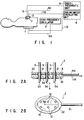
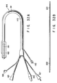
- FIGS. 1, 2A, 2B and 3 show the first embodiment of the invention.
- FIG. 1 is schematic representation of a medical apparatus which has a thermotherapeutic applicator.
- the medical apparatus has a thermotherapeutic applicator, a high-frequency oscillator 3, a cooling water circulating unit 4, radiotherapeutic applicators 5, and a radiotherapeutic unit 6.
- the thermotherapeutic applicator is comprised of an extracorporeal applicator 1 and a superficial applicator 2.
- the extracorporeal applicator 1 is mounted on a patient.
- the superficial applicator 2 is smaller than the extracorporeal applicator 1 but large enough to reliably heat an affected part of the patient, such as tumor 7.
- the applicators 1 and 2 are connected to the high-frequency oscillator 3 and also to the cooling water circulating unit 4.
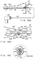
- FIG. 2A is a sectional side view of the applicator 2
- FIG. 2B is a side view of the applicator 2, as viewed in the direction of arrow A (FIG. 2A).
- the superficial applicator 2 has a main body 22 and a balloon 10.
- the main body 22, or thick-wall receptacle 22 contains an electrode 8.
- the electrode 8 is electrically connected to the high-frequency oscillator 3 by an electrode wire 9a.
- the balloon 10 is provided on that side of the receptacle 22 which may contacts a patient's body surface.
- the balloon 10 is connected to the cooling water circulating unit 4 by a cooling tube 11a which extends through the thick-wall receptacle 22.
- the cooling tube 11a has a water supplying passage and a water discharging passage. Through the water supplying passage the cooling water is supplied from the cooling water circulating unit 4 into the balloon 10. Through the water discharging passage the cooling water is returned from the balloon 10 back into the cooling water circulating unit 4.
- the cooling water circulating unit 4, the water supplying passage, the balloon 10 and the water discharging passage constitute a loop. It is through this loop that the cooling water is circulated through during the use of the thermotherapeutic applicator including the superficial applicator 2. While flowing through the cooling tube 11a, the water cools the electrode 8 contained in the receptacle 22 because the tube 11a extends through the thick-wall receptacle 22. Since the electrode 8 is thus cooled, it would not cause a burn at the body surface on which the receptacle 22 containing the electrode 8 is mounted.
- a temperature sensor 50 On the balloon 10 there is mounted a temperature sensor 50, which is connected by a signal line 51 to, for example, a control device (not shown).
- the control device is designed to control the high-frequency oscillator 3 and the cooling water circulating unit 4 in accordance with a signal which is supplied via the signal line 51 from the temperature sensor 50 and which represents the temperature the sensor 50 has detected.
- the superficial applicator 2 has a plurality of through holes 12.
- the holes 12 have a diameter large enough to allow the passage of the radiotherapeutic applicators 5.
- each radiotherapeutic applicator 5 is connected to the radiotherapeutic unit 6.
- Each radiotherapeutic applicator 5 has a pointed tip 5a as is illustrated in FIG. 2A.
- Each applicator 5 is a tubular member, into which a radiation source 13 can be supplied from the radiotherapeutic unit 6.
- the extracorporeal applicator 1 contains an electrode (not shown). This electrode is electrically connected to the high-frequency oscillator 3 by an electrode wire 9b.
- the extracorporeal applicator 1 has a cooling water passage (not shown), which is connected to the cooling water circulating unit 4 by a cooling water tube 11b.
- thermotherapeutic applicator to conduct thermotherapy on the tumor 7.
- the extracorporeal applicator 1 and the superficial applicator 2 are secured to the patient.
- the applicators 1 and 2 are located, opposing each other such that the tumor 7 is positioned between them. If the tumor 7 is present near the body surface, the superficial applicator 2 is located above the tumor 7 as shown in FIG. 3, with the balloon 10 set in contact with the body surface.
- the radiotherapeutic applicators 5 are passed through the holes 12 of the superficial applicator 2, until their pointed tips 5a pierce into the tumor 7.
- the high-frequency oscillator 3 is driven, supplying a high-frequency current to the electrode 8 of the thermotherapeutic applicator 2.
- the current flows between the electrode 8 of the applicator 2 and that (not shown) of the extracorporeal applicator 1.
- the current flows through the tumor 7 located between these electrodes.
- the tumor 7 is thereby heated.
- the cooling water is circulated in the balloon 10 by means of the cooling water circulating unit 4, preventing the patient from suffering a burn at the body surface.
- radiotherapy is carried out, too.
- radiation sources 13 are introduced from the radiotherapeutic unit 6 into the radiotherapeutic applicators 5 as is illustrated in FIG. 3.
- the source in each applicator 5 emits radiation, which is applied in the tumor 7.
- the medical apparatus enables a surgeon to perform thermotherapy and radiotherapy at the same time and, hence, to treat an affected part of a patient effectively.
- thermotherapeutic applicator can supply the high-frequency current concentratedly to the tumor 7, thereby heating the tumor 7 but not any unaffected tissues near the tumor 7. This is because, as mentioned above, the thermotherapeutic applicator is smaller than the superficial applicator 2 but large enough to reliably heat the tumor 7 entirely.
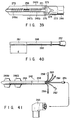
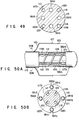
- FIG. 4 shows the second embodiment of the present invention. More correctly, it shows the superficial applicator 2a which is provided in another medical apparatus according to the invention.
- the superficial applicator 2a differs from its counterpart of the first embodiment (FIGS. 1, 2A, 2B and 3), in two respects.
- the through holes 12 extend slantwise to guide the radiotherapeutic applicators 5 into the tumor 7 along inclined paths.
- the electrode wire 9a and the node of the water supplying tube 11a 1 and the water discharging tube 11a 2 are on that side of the applicator 2a which faces away from the side to contact the tumor 7 (i.e., the side on which the balloon 10 is provided).
- the wire 9a or the tubes 11a 1 and 11a 2 do not hinder the insertion of the radiotherapeutic applicators 5 though the holes 12 into the tumor 7.
- the components of the second embodiment, other than the superficial applicator 2a, are essentially identical in structure to those of the first embodiment (including the extracorporeal applicator 1).
- the second embodiment is advantageous over the first embodiment in two respects.
- the radiotherapeutic applicators 5 can apply radiation to a more limited region within the tumor 7, by using the same number of radiation sources 13 as in the first embodiment.
- the position of each radiation source 13 can be changed in the radiotherapeutic applicator 5, which is inserted into the tumor 7 slantwise, not vertically, as shown in FIG. 4.
- the radiation sources 13 may first located in the distal ends of the applicators 5, emitting radiation to an inner part of the tumor 7, and then moved toward the proximal ends of the applicator 5, emitting radiation to a near-surface part of the tumor 7.
- the tumor 7 can be heated, first at the inner part and then at near-surface part.
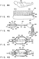
- FIG. 5 illustrates the third embodiment of the present invention. To be more precise, FIG. 5 shows the superficial applicator 2b which is provided in another medical apparatus according to the invention.
- the superficial applicator 2b differs from its counterpart of the first embodiment (FIGS. 1, 2A, 2B and 3).
- the applicator 2b comprises a cup-shaped support 14, an applicator body 22a fastened to the bottom of the support 14, an electrode 8 contained in the body 22a, and a balloon 10 provided on that side of the receptacle 22 which may contact a patient's body surface.
- the balloon 10 is exposed to the interior of the cup-shaped support 14 and positioned so as to contact the top of a tumor 7 when support 14 covers the tumor 7.
- the support 14 has through holes 12 in its circumferential wall. Through these holes 12 the radiotherapeutic applicators 5 can be inserted into the tumor 7.
- the components of the third embodiment, other than the superficial applicator 2b, are basically the same in structure as those of the first embodiment (including the extracorporeal applicator 1).
- the superficial applicator 2b is used in the following way to accomplish thermotherapy and radiotherapy simultaneously.
- the applicator 2b is positioned such that the cup-shaped support 14 covers the tumor 7, and the balloon 10 is thereby set in contact with the top of the tumor 7.
- the medical apparatus is operated in the same manner as the first embodiment, whereby both thermotherapy and radiotherapy are conducted on the tumor 7 at the same time.
- the superficial applicator 2b enables a surgeon to simultaneously perform radiotherapy and thermotherapy, effectively treating the tumor 7 which is prominently bulbous.
- FIGS. 6A and 6B show the fourth embodiment of this invention.
- FIG. 6A is a sectional side view of the superficial applicator 2c provided in a medical apparatus which is the fourth embodiment
- FIG. 6B shows the applicator 2c as viewed from a balloon 10.
- the superficial applicator 2c differs in structure from its counterparts of the first to third embodiments (FIGS. 1-3, FIG. 4 and FIG. 5). As shown in FIGS. 6A and 6B, the superficial applicator 2c has through holes 12 concentratedly in its center part and contains an electrode 8 which is far larger than the center part.
- the components of the fourth embodiment, other than the superficial applicator 2b, are basically the same in structure as those of the first embodiment.
- the superficial applicator 2c enables the radiotherapeutic applicators 5 to apply radiation to the entire tumor 7, and the electrode 8 supplies the high-frequency current to the region 15, heating not only the tumor 7 but also the tissues near the tumor 7.
- thermotherapy can be conducted on the tumor 7, even at the surface portion thereof which is usually hard to be heated sufficiently. In other words, no part of the tumor 7 remains not completely subjected to thermotherapy.
- the region 15 receiving the high-frequency current from the electrode 8 is relatively large, the unaffected tissues present near the tumor 7 are not damaged by the high-frequency current because they are resistant to heat unlike the tumor 7 which is an affected tissue.
- FIG. 7 illustrates the fifth embodiment of this invention.
- FIG. 7 shows the major components of the intra-cavity applicator 16 incorporated in a medical apparatus which is the fifth embodiment.
- the applicator 16 is devised to heat a tubular organ, particularly the rectum.
- the intra-cavity applicator 16 has a flexible insertion section 18.
- An electrode 19 is wound around the distal end of the insertion section 18, forming a coil.
- the electrode 19 is electrically connected to the high-frequency oscillator 3 by an electrode wire which extends through the insertion section 19.
- a balloon 20 is mounted on the distal end of the insertion section 18, surrounding the electrode 19.
- the insertion section 18 has a hole (not shown) for supplying and discharging cooling water. Cooling water flows through this hole into and out of the balloon 20.
- the hole communicates with the cooling water circulating unit 4 of the type shown in FIG. 1. The cooling water can therefore flows back and forth, between the cooling water circulating unit 4 and the balloon 20.
- a pair of applicator supports 17 protrude sideways from the insertion section 18, at the back of the balloon 20.
- the supports 17 abut on the entrance to the tubular organ when the insertion section 18 is inserted into a tubular organ.
- the supports 17 prevent a further insertion of the section 18 into the tubular organ.
- Each support 17 has a plurality of through holes 12 for guiding the radiotherapeutic applicators 5.
- intra-cavity applicator 16 is used to treat a tumor 7 on the rectum.
- the insertion section 18 is inserted into the rectum through the anus 40 until the entire electrode 19 is located in the rectum.
- the cooling wafer is pumped from the cooling water circulating unit 4 into the balloon 20, inflating the balloon 20.
- the balloon 20 comes into contact with the tumor 7, thus positioning the insertion section 18 in the rectum.
- the cooling water is continuously circulated in the hole for supplying and discharging the cooling water, whereby the muscous membrane is prevented from heated to an excess.
- the supports 17 abut the body surface, at a position near the anus 40.
- the radiotherapeutic applicators 5 are inserted into the tumor 7 through the holes 12 of the supports 17. Having a pointed dip 5a, each applicator 5 can smoothly pierce into the tumor 7. Thereafter, the medical apparatus is operated in the same manner as the first embodiment, whereby both thermotherapy and radiotherapy are performed on the tumor 7 at the same time.
- the intra-cavity applicator 16 enables a surgeon to simultaneously perform radiotherapy and thermotherapy on not only the rectum but also any other tubular organ existing near the body surface.
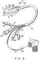
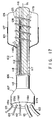
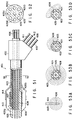
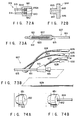
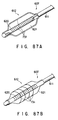
- FIGS. 8 and 9 show the sixth embodiment of this invention, more correctly the thermotherapeutic applicator 60 incorporated in a medical apparatus according to the sixth embodiment.
- the thermotherapeutic applicator 60 has a main body 61 which comprises a shaft 61a and an electrode support 61b coupled to the distal end of the shaft 61a.
- the shaft 61a is made of a soft material such as silicone rubber.
- the electrode support 61b is made of silicon rubber or the like, too.
- Embedded in the electrode support 61b is an electrode 62 for supplying a high-frequency current.
- the electrode 62 is, for example, a copper plate.
- a radiation source tube 63, a coolant supplying tube 66, a coolant discharging tube 67, a RF supplying line 68, and a signal supplying line 69 extend through the shaft 61a.
- the RF supplying line 68 is connected at its distal end to the electrode 62 which is provided to supply a high-frequency current.
- the proximal end of the RF supplying line 68 extends outwards from the proximal end of the shaft 61a.
- the proximal end of the RF supplying line 68 is connected to a RF connector 68a. It is through the RF supplying line 68 that radio-frequency (RF) power is supplied to the electrode 62.
- RF radio-frequency
- the radiation source tube 63 is made of material having a small friction coefficient, such as fluororesin.
- the tube 63 has its distal end portion inserted in the electrode support 61b.
- the proximal end portion of the tube 63 extends outwards from the proximal end of the shaft 61a.
- the proximal end of the radiation source tube 63 is connected to a radiation source connector 63a, which can be connected to a radiation source remote-controller 71.
- One side of the electrode support 61b is covered with a thin film 64 made of, for example, silicone rubber.
- the interior of the thin film 64 communicates with the distal end of the coolant supplying tube 66 and that of the coolant discharging tube 67.
- the proximal end portion of the coolant supplying tube 66 protrudes outwards from the proximal end of the shaft 61a.
- a coolant inlet connector 66a is mounted on the proximal end of the coolant supplying tube 66.
- the proximal end portion of the coolant discharging tube 67 protrudes outward from the proximal end of the shaft 61a.
- the proximal end of the shaft 61a is connected to a coolant outlet connector 67a. Coolant such as purified water is supplied into the interior of the thin film 64 through the coolant supplying tube 66, and is discharged from thin film 64 through the coolant discharging tube 67.
- Temperature sensors 65a and 65b are provided on the thin film 64.
- the temperature sensors 65a and 65b are connected to the distal ends of the signal supplying line 69.
- the proximal end portion of the line 69 extends outwards from the proximal end of the shaft 61a.
- FIG. 9 is a longitudinal sectional view of the electrode support 61b.
- the radiation source tube 63 contains a radiation source 73 introduced thereinto by operating the radiation source remote-controller 71 (FIG. 8).
- thermotherapeutic applicator 60 To use the thermotherapeutic applicator 60, the coolant inlet connector 66a, the coolant outlet connector 67a, the RF connector 68a and the temperature sensor connector 69a are connected to a thermotherapeutic device (not shown).
- the thermotherapeutic device incorporates a cooling water circulating unit, a RF source and various drive units, which are not shown.
- the electrode support 61b of the thermotherapeutic applicator 60 is attached to the patient, with the thin film 64 contacting the body surface.
- An electrode (not shown) is also attached to the patient, to oppose the electrode 62 held within the support 61b. This electrode is connected to the thermotherapeutic device. Thermotherapy can then be performed on a tumor present in the body surface of the patient.
- the radiation source remote-controller 71 is operated, introducing the radiation source 73 from the radiation source connector 63a into the distal end portion of the radiation source tube 63. Therefore, radiotherapy is conducted on the tumor, along with the thermotherapy.
- the medical apparatus according to the sixth embodiment can therefore enable a surgeon to simultaneously perform thermotherapy by using electromagnetic waves and radiotherapy by using the radiation source 73, on a tumor present in the body surface of a patient.
- the tumor can be treated effectively within a short time, not inflicting much pain on the patient.
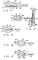
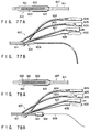
- FIG. 10 shows the seventh embodiment of the present invention.
- FIG. 10 is a side view of the thermotherapeutic applicator used in a medical apparatus which is the seventh embodiment.
- This applicator is a modification of the thermotherapeutic applicator (FIGS. 8 and 9) of the sixth embodiment.
- the thermotherapeutic applicator has three radiation source tubes 81a, 81b and 81c.
- the tubes 81a to 81c extends through a shaft 61a, and their distal end portions are provided in a electrode support 61b, extending parallel to one another.
- the proximal end portions of the radiation source tubes 81a to 81c extend outwards from the proximal end of the shaft 61a.
- Mounted on the proximal ends of the tubes 81a to 81c are radiation source connectors 82a, 82b and 82c which can be connected to a radiation source remote-controller 71 of the same type shown in FIG. 8.
- the sensing section of a temperature sensor 83 is provided in the distal end portion of the tube 81b which is located in the middle part of the electrode support 61b.
- thermotherapeutic applicator of the seventh embodiment is identical to that of the sixth embodiment, which is shown in FIGS. 8 and 9.
- the applicator can apply radiation to a larger region in a tumor, than can the applicator 60 which has only one radiation source tube 63 only if all tubes 81a to 81c contain a radiation source 73 each.
- One, two or all of the tubes 81a to 81c may contain a radiation source each, to distribute the radiation in three different manners in an affected part of a patient. This also helps to treat the affected part effectively.
- the tubes 81a to 81c be arranged at intervals of about 5 to 15 mm.
- the number of radiation source tubes is not limited to three. Rather, the thermotherapeutic applicator may have two radiation source tubes or more than three radiation source tubes.
- FIG. 11 shows the eight embodiment of the present invention. More correctly, it illustrates the major components of the thermotherapeutic applicator incorporated in a medical apparatus which is the eighth embodiment.
- the applicator is identical to the thermotherapeutic applicator of the seventh embodiment, except that the distal end portions of the radiation source tubes 81a to 81c extend in the electrode support 61b -- not parallel to one another.
- the distal end portion of the tube 81b extends along the axis of the shaft 61a.
- the distal end portions of the tubes 81a and 81c are inclined to the axis of the shaft 61a, gradually flaring away from the shaft 61a toward their distal ends.
- thermotherapeutic applicator of the seventh embodiment is advantageous in three respects. First, it can distribute radiation in high density when radiation sources are located in the proximal parts of the radiation source tubes 81a to 81c, because the proximal parts of the tubes 81a to 81c are arranged at short intervals. Secondly, the applicator can distribute radiation in low density when radiation sources are located in the distal parts of the radiation source tubes 81a to 81c, because the distal parts of the tubes 81a to 81c are arranged at long intervals. Thirdly, the radiation sources may be moved in the respective tube 81a to 81c, between the distal and proximal end of each tube, to thereby change the distribution of radiation to any type desired. This serves to enhance the effect of therapy.
- FIG. 12 shows the ninth embodiment of the present invention. More precisely, it illustrates the major components of the thermotherapeutic applicator incorporated in a medical apparatus which is the ninth embodiment.
- the applicator is a modification of the thermotherapeutic applicator (FIG. 10) of the seventh embodiment.
- the sensing section of the temperature sensor 87 is positioned in the middle part of the electrode support 61b.
- Two radiation source tubes 86a and 86b are provided in the support 61b, located on the sides of the temperature sensor 87.
- the distal end portions of the extend parallel to each other, not overlapping within the electrode support 61b.
- the thermotherapeutic applicator is identical to its counterpart (FIG. 10) of the seventh embodiment.
- the temperature sensor 87 Since the temperature sensor 87 is not located between the affected part of a patient and the radiation sources 73 contained in the tubes 86a and 86b, the radiation emitted from the sources 73 is not blocked by the temperature sensor 87. In addition, the radiation emitted from the sources 73 can be distributed in the affected part in uniform density, thereby improving the efficiency of therapy.
- a radiation source 73 need not be introduced into both radiation source tubes 86a and 86b. It may be introduced into only one of the tubes 86a and 86b.
- FIG. 13 illustrates the tenth embodiment of this invention. To state it more specifically, it shows the major components of the thermotherapeutic applicator incorporated in a medical apparatus which is the tenth embodiment.
- the applicator is a modification of the thermotherapeutic applicator (FIG. 10) of the seventh embodiment.
- thermotherapeutic applicator has three radiation source tubes 88a, 88b and 88c which extend through the shaft 61a as illustrated in FIG. 13.
- the distal end portions of the tubes 88a to 88c extend parallel in the electrode support 61b.
- thermotherapeutic applicator is identical to its counterpart (FIG. 10) of the seventh embodiment.
- thermotherapeutic applicator of the tenth embodiment can therefore achieve the same advantages as that of the seventh embodiment.
- the radiation source tubes 88a to 88c need not be arranged parallel to each other if the temperature sensors 89a and 89b do not overlap in the space between the radiation sources 73 on the one hand and the affected part of the patient on the other.
- FIG. 14 shows a medical apparatus according to the eleventh embodiment of this invention, which has a thermotherapeutic applicator designed to apply thermotherapy on women's breasts.
- thermotherapeutic applicator is identical to its counterpart of the first embodiment, except that it has two superficial applicators 2d as illustrated in FIG. 14. Each superficial applicator 2d has a plurality of holes 12 in one side. The holes 12 extend parallel to one another. Radiotherapeutic applicators of the same type shown in FIG. 1 can be inserted into the holes 12, but not into the patient's breast 70.
- thermotherapeutic applicator is used to treat a tumor 7 which exists at a relatively deep position in the woman's breast 70.
- the superficial applicators 2d are positioned, clamping the patient's breast 70. Using both superficial applicators 2d, a surgeon applies heat to the tumor 7 within the patient's breast 70.
- the surgeon can perform radiotherapy on the patient's breast 70 without piercing the radiotherapeutic applicators into the breast 70 -- at the same time he or she carries out thermotherapy on the breast 70.
- FIGS. 15A and 15B illustrate a thermotherapeutic applicator incorporated in a medical apparatus according to the twelfth embodiment of the invention.
- the thermotherapeutic applicator comprises a superficial applicator 2d and an extracorporeal applicator 21, which are to clamp the breast 70 of a female patient.
- the extracorporeal applicator 21 is an electrode which is larger than that of the superficial applicator 2d. Designed to treat a tumor in the woman's breast, the applicator 21 has a smaller contacting area than the extracorporeal applicator 1 of the first embodiment. Only the superficial applicator 2d has holes 12 into which radiotherapeutic applicators are to be inserted.
- thermotherapeutic applicator of the twelfth embodiment is used to treat a tumor 7 present in the surface of the woman's breast 70.
- the superficial applicator 2d is placed on that portion of the breast 70 in which the tumor 7 is present, and the extracorporeal applicator 21 is placed on that portion of the breast 70 which opposes the tumor 7.
- the applicators 2d and 21 clamp the patient's breast 70 between them.
- the medical instrument enables a surgeon to conduct effective thermotherapy and radio therapy on the tumor 7 at the same time, without excessively heating the normal tissues surrounding the tumor 7 in the breast 70 or exposing the normal issues to radiation.
- FIGS. 16A and 16B show a medical apparatus according to the thirteenth embodiment of the present invention. More precisely, they show the superficial applicator 2e.
- the superficial applicator 2e is shaped like a ring, to be mounted on the breast 70 of a female patient.
- Two electrodes 23 and 24, both in the form of letter C, are embedded in the superficial applicator 2e.
- the electrodes 23 and 24 are electrically insulated by insulating members 22 which are interposed between the opposing ends of the electrodes 23 and 24.
- the electrodes 23 and 24 are connected to a high-frequency oscillator 3.
- the superficial applicator 2e has a balloon 10 on the inner circumferential surface. Cooling water tubes 25 an 26 are connected at one end to the balloon 10 and at the other end to a cooling water circulating unit 4. Cooling water is supplied from the unit 4 into the balloon 10 through the tube 25 and discharged from the balloon 10 back into the unit 4 through the tube 26.
- the applicator 2e has holes 12 in one side, into which radiotherapeutic applicators can be inserted. Except for these features, the superficial applicator 2e is exactly the same as its counterpart 2 of the first embodiment (FIGS. 1 to 3).
- the superficial applicator 2e surrounds the breast 70 and serves to conduct thermotherapy and radiotherapy simultaneously on the entire breast 70.
- the applicator 2e enables a surgeon to perform efficiently, particularly in the case where a large tumor 7 is present in the patient's breast 70.
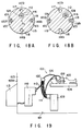
- FIGS. 17, 18A, 18B, 19, 20A to 20E and 21 A medical apparatus which is the fourteenth embodiment of the present invention will be described, with reference to FIGS. 17, 18A, 18B, 19, 20A to 20E and 21.
- FIG. 19 is a schematic representation of this medical apparatus 101 which is installed in an operating room 103.
- the room 103 is electromagnetically shielded from any other room by radiation-shielded walls 103a.
- Installed also in the operating room 103 is a bed or an operating table 104, on which a patient 105 lies.
- the medical apparatus 101 comprises an intra-cavity applicator 102, an extracorporeal applicator 108, a hyperthermia device 109, a radiotherapeutic device 110, and a radiotherapy controller 113.
- the applicators 108 and 109 both fixed to the patient 105, are connected to the hyperthermia device 109 by cables and tubes 111.
- a radiation source tube 112 is connected at its proximal end to the radiotherapeutic device 110.
- the radiotherapy controller 113 is provided outside the operating room 103 and connected to the radiotherapeutic device 110.
- the intra-cavity applicator 102 comprises an insertion section 106 and a proximal section 107.
- the insertion section 106 can be inserted into a body cavity of the patient 102.
- the proximal section 107 is coupled to the proximal end of the insertion section 106.
- FIG. 17 shows the major components of the intra-cavity applicator 102.
- the insertion section 106 of the applicator 102 comprises a flexible shaft 115.
- the shaft 115 has a radiation source passage 116 which extends parallel to the axis O 1 .
- the shaft 115 has a multi-lumen structure.
- Four parallel lumina 117 to 120 are provided in the circumferential surface of the shaft 115 and extend parallel to the axis O 1 thereof.
- the four lumina 117 to 120 are used as a cooling water supplying passage 117, a cooling water discharging passage 118, a temperature sensor guiding hole 119, and an electrode cable passage 120.
- the lumina 117 to 120 need not take the positions specified in FIG. 18A. Rather, they may be arranged at other positions, as long as each has ends opening at the distal and proximal ends of the shaft 115, respectively. Likewise, the radiation source passage 116 need not assume the position shown in FIG. 18A; it may take a different position, so long as it extends parallel to the axis O 1 of the shaft 115.
- the proximal end of the intra-cavity applicator 102 has five openings 116a to 120a, which are the proximal ends of the radiation source passage 116, cooling water supplying passage 117, cooling water discharging passage 118, temperature sensor guiding hole 119, and electrode cable passage 120.
- a water supplying tube 121 is connected at the distal end to the opening 117a of the cooling water supplying passage 117.
- a water discharging tube 122 is connected at the distal end to the opening 118a of the cooling water discharging passage 118.
- a temperature sensor cable 123 is inserted into the opening 119a, an electrode cable 124 is inserted into the opening 120a, and a radiation source guiding tube 112 is inserted into the opening 116a.
- a high-frequency electrode 125 is coiled around the distal end portion of the shaft 115.
- a balloon 126 is mounted on the distal end portion of the shaft 115, covering the high-frequency electrode 125.
- the electrode 125 is not limited to a coiled one. It may be replaced by a mesh electrode or a plate-like electrode.
- the balloon 126 is made of an elastic sheet and secured at its front end to the distal end portion of the shaft 115 , and at its rear end to the proximal end portion of the shaft 115.
- the distal end portion of the shaft 115 is located in front of the high-frequency electrode 125, and the proximal end portion thereof is located at the back of the electrode 125.
- the intra-cavity applicator 102 has four openings 117b to 120b in the circumferential surface of its distal end portion.
- the openings 117b to 120b are the proximal ends of the cooling water supplying passage 117, cooling water discharging passage 118, temperature sensor guiding hole 119, and electrode cable passage 120. Of these openings, the openings 117b, 118b and 120b open to the interior of the balloon 126.
- the cooling water is supplied into the balloon 126 through the cooling water supplying passage 117 and discharged from the balloon 126 through the cooling water discharging passage 118. Thus, the cooling water is circulated in the balloon 126.
- An electrode cable 124 extends through the electrode cable passage 120. The distal end portion of the cable 124 projects into the balloon 126 from the opening 120b of the electrode cable passage 120. The electrode cable 124 is connected at its distal end to the high-frequency electrode 125.
- the opening 119a of the temperature sensor guiding hole 119 opens to the exterior of the balloon 126.
- a temperature sensor cable 123 extends through the hole 119 and is connected at its distal end to a temperature sensor 127. The distal end portion of the cable 123 protrudes through the opening 119a from the shaft 115, at a position in front the balloon 126.
- the temperature sensor 127 is mounted on the balloon 126; it is, for example, a thermocouple, a temperature sensor having a platinum element, an optical-fiber temperature sensor, a thermistor, or the like.
- a radiation source tube 112 Inserted in the radiation source passage 116 of the shaft 115 is a radiation source tube 112 which contains a radiation source 128. As shown in FIG. 17, the radiation source 128 is located in the middle part of that heating section of the shaft 115, around which the high-frequency electrode 125 is wound.
- the radiation source passage 116 need not extend to the distal end of the shaft 115. Rather, it may extends only to a position where the radiation source 128 is located to oppose the balloon 126. In this case, the shaft 115 has no opening at its distal end at all. The the radiation source 128 is automatically set at that position when the radiation source tube 112 is inserted into the passage 116 until its distal end abuts on the closed end of the passage 116. Since the radiation source passage 116 extends not along the axis O 1 of the shaft 115 but parallel thereto, the radiation source 128 can be located near the tumor, when moved along the circumferential surface of the shaft 115 by rotating the shaft 115.
- the medical apparatus according to the fourteenth embodiment is used in the operating room 103 which is electromagnetically shielded from any other room by radiation-shielded walls 103a as shown in FIG. 19.
- the water supplying passage 117 and the water discharging tube 122 are evacuated.
- the cooling water is thereby drawn from the balloon 11, deflating the balloon 126.
- the insertion section 106 of the intra-cavity applicator 102 is inserted into the body cavity of the patient 105.
- the radiation source tube 112 is inserted into the passage 116, either before or after the insertion section 106 is inserted into the body cavity.
- the insertion section 106 After the insertion section 106 is inserted into the body cavity, cooling water is supplied into and circulated in the balloon 126.
- the balloon 126 is thereby inflated and comes into contact with the inner surface of the body cavity. As a result of this, the distal end portion of the intra-cavity applicator 102 is held steadfastly in the body cavity.
- the intra-cavity applicator 102 can be inserted into the esophagus H 2 of a patient via the mouth H 1 , as is shown in FIG. 20A.
- the applicator 102 may be inserted into the S-colon H 5 or the colon H 6 through the rectum H4, as is illustrated in FIG. 20B.
- the applicator 102 may be inserted into the bile duct H 8 of a patient, which is located in the vicinity of the lever H 7 , as is illustrated in FIG. 20C. Further, the applicator 102 may be inserted into the trachea H 9 and bronchus H 11 of a patient, both located near the lung H 10 , as is shown in FIG. 20D.
- the applicator 102 may be inserted into the bladder H 13 and prostate H 14 through the urethra H 12 , as is illustrated in FIG. 20E. Moreover, the applicator 102 may be inserted into the uterus H 16 through the vagina H 15 , as is shown in FIG. 21.
- the insertion section 106 of the intra-cavity applicator 102 is inserted into the body cavity and held at the affected part to be treated.
- the applicator 102 is then used to conduct thermotherapy and radiotherapy on the affected part.
- the order of the therapy steps differs in accordance with the protocol chosen by the surgeon who uses the medical apparatus 101.
- a high-frequency current is supplied to the high-frequency electrode 125, thereby initiating hyperthermia.
- the surgeon steps out of the operating room 103 which is electromagnetically shielded.
- the hyperthermia device 109 can continue the thermotherapy by hyperthermia reliably, only if device 109 can automatically control the hyperthermia temperature.
- the hyperthermia device 109 is positioned such that the surgeon can see the hyperthermia temperature displayed on the display panel on the device 109. It is desirable that a monitor be provided outside the room 103 to display the changes in hyperthermia temperature.
- the surgeon begins to perform radiotherapy. More precisely, he or she manipulates the radiotherapy controller 113 which is provided outside the operating room 103 and which is connected to the radiotherapeutic device 110.
- the radiation source 128 is introduced into the body cavity of the patient 105 from the device 110 through the radiation source tube 112.
- the source 128 is located in the distal end of the shaft 115 of the applicator, off the axis O 1 of the shaft 115 as illustrated in FIG. 17. This is because the tube 112 extends parallel to the axis O 1 of the shaft 115 of the applicator 102, not along the axis O 1 .
- the radiation source 128 emits radiation, whereby the affected part present in the body cavity is subjected to radiotherapy for a prescribed time.
- the surgeon operates the radiotherapy controller 113, moving the radiation source 128 back into the radiotherapeutic device 110.
- the hyperthermia device 109 keeps on operating, whereby the hyperthermia is continued.
- the hyperthermia is automatically stopped upon lapse of a predetermined time.
- the source 128 emits a low dose of radiation
- the radiation needs to be applied onto the affected part for a longer period of time.
- the surgeon selects a protocol of starting and stopping the hyperthermia device 109 during the radiotherapy achieved by operating the radiotherapeutic device 110.
- the heating by means of the device 109 may be started while the device 110 is being operated to conduct the radiotherapy.
- surgeon may selects a protocol of starting the hyperthermia device 109 after the radiotherapeutic device 110 has completed the radiotherapy, or a protocol of starting the radiotherapeutic device 110 after the hyperthermia device 109 has completed the hyperthermia. In either protocol, the intra-cavity applicator 102 is employed.
- the medical apparatus 101 described above is advantageous in several respects.
- the apparatus 101 enables the surgeon to treat an affected part of a patient, such as cancer, with high efficiency, since the hyperthermia device 109 and the radiotherapeutic device 110 can be operated to perform hyperthermia and radiotherapy at the same time.
- the radiation emitted from the source 128 can be applied concentratedly onto an affected part present on the inner surface of a body cavity. This is because the source 128 is located off the axis O 1 of the shaft 115 and can be moved to a position near the affected part by rotating the shaft 115.
- the intra-cavity applicator 102 serves to accomplish effective radiotherapy, as well as thermotherapy.
- the surgeon needs to insert the applicator 102 into the body cavity, but only once, in order to perform both radiotherapy and hyperthermia in the body cavity, because the applicator 102 has the high-frequency electrode 125 and contains the radiation source 128.
- the radiation source 128 is surrounded by the coiled high-frequency electrode 125, it would not distort the temperature distribution which the hyperthermia achieves in the affected part.
- the applicator 102 can be disinfected easily, provided that the distal end of the radiation source passage 116 is closed by some means.
- the radiation source passage 116 of the shaft 115 may be opened at its distal end.
- the shaft 115 of the applicator 102 can then be made more easily than in the case where the passage 116 is closed at its distal end.
- the passage 116 can serve not only to guide the radiation source 128, but also to guide a guide wire or the insertion section of an endoscope or to supply air.
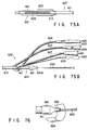
- FIGS. 22A and 22B A medical apparatus according to the fifteenth embodiment of the present invention will be described, with reference to FIGS. 22A and 22B.
- This apparatus is a modification of the fourteenth embodiment 101 (FIGS. 17 to 21) and is characterized in the structure of the intra-cavity applicator 102.
- the shaft 115 has a radiation source passage 116 which is aligned with the axis O 1 and four lumina 117 to 120 which extend parallel to the axis O 1 and, hence, to the radiation source passage 116.
- a balloon 131 is mounted on the distal end portion of the shaft 115.
- the balloon 131 is eccentric to the shaft 115.
- its axis O 2 extends parallel to the axis O 1 of the shaft 115.
- the radiation source passage 116 need not be axially aligned with the shaft 115, only if it is not axially aligned with the balloon 131.
- the intra-cavity applicator 102 of the fifteenth embodiment is identical to its counterpart of the fourteenth embodiment (FIGS. 17 to 21).
- the radiation source passage 116 is aligned with the axis O 1 and the balloon 131 is eccentric to the shaft 115.
- the radiation source 128 inserted in the passage 116 can therefore emit radiation downwards (FIG. 22B) -- that is, in the direction opposite to the one in which the axis O 2 of the balloon 131 is deviated from the axis O 1 of the shaft 115.
- the radiation emitted from the source 128 can be applied concentratedly onto an affected part present on the inner surface of a body cavity, as in the fourteenth embodiment.
- the intra-cavity applicator 102 can therefore enables the surgeon to perform both radiotherapy and thermotherapy effectively.
- the radiation source passage 116 need not be axially aligned with the shaft 115.
- the passage 116 may not axially aligned with the shaft 115, provided that its axis is not aligned with the axis O 2 of the balloon 131. This makes it possible to arrange the passage 116 and other passages at any desired positions in the shaft 115. It is therefore easy to design the intra-cavity applicator 102.
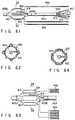
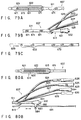
- FIGS. 23A and 23B show the sixteenth embodiment of the present invention, more correctly the intra-cavity applicator provided in a medical apparatus which is the sixteenth embodiment.
- the applicator is a modification of the applicator 102 of the fourteenth embodiment (FIGS. 17 to 21). It is characterized in that the shaft 115 has a recess 141 in the circumferential surface of its distal end portion, on which a balloon 126 is mounted.
- the radiation source passage 116 opens at the proximal and distal ends of the recess 141.
- the four lumina 117 to 120 are provided in the shaft 115, not opening to the recess 141 at all.
- connection tube 142 is placed in the recess 141, connecting the open ends of the radiation source passage 116.
- the connection tube 142 serves to position the radiation source tube 112 in the balloon 126.
- the radiation source tube 112 is guided through the radiation source passage 116.
- the connection tube 142 can be dispensed with. Even if the tube 142 is not provided, the radiation source tube 112 can be positioned well.
- the radiation source passage 116 may be closed at the distal end of the recess 141, or a small recess may be formed in the shaft 115 at the distal end of the recess 141.
- the small recess if formed, serves to position the distal end of the radiation source tube 112.
- the radiation source passage 116 opens at the proximal and distal ends of the recess 141 which is made in the circumferential surface of the shaft 115 and which is surrounded by the balloon 126.
- the radiation source 128 inserted in the passage 116 can therefore emit radiation downwards (FIG. 23B) along the line connecting the axis O 1 of the shaft 115 and the axis of the passage 116.
- the radiation emitted from the source 128 can be applied concentratedly onto an affected part present on the inner surface of a body cavity, in the same way as in the fourteenth embodiment.
- the intra-cavity applicator 102 can enables the surgeon to perform both radiotherapy and thermotherapy effectively.
- the high-frequency electrode 125 would not affect the distribution of radiation emitted from the radiation source 128, because the source 128 surrounded by the coiled high-frequency electrode 125.
- the radiation source 128 can be reliably positioned since the connection tube 142 is placed in the recess 141, connecting the open ends of the radiation source passage 116.
- the tube 142 can be dispensed with, to simplify the structure of the applicator 102 and, hence, to reduce the manufacturing cost thereof.
- FIG. 24 illustrates the shaft 115 of the intra-cavity applicator used in a medical apparatus which is the seventeenth embodiment of the present invention.
- the intra-cavity applicator is a modification of the applicator 102 of the fourteenth to sixteenth embodiments. It is different in that a smoothing layer 151 made of, for example, Teflon, is coated on the inner circumferential surface of the radiation source passage 116 of the shaft 115.
- the friction between the layer 151 and the radiation source tube 112 inserted in the passage 116 is low, and the tube 112 can be smoothly guided through the passage 116 even if it is comparatively long. Without the smoothing layer 151, it would be difficult for a surgeon to insert the tube 112 deep into the passage 116, particularly so if the shaft 115 is made of silicone or the like. The friction would be so great that the tube 112 can hardly be guided to the distal end of the passage 116 even if the diameter of the passage 116 is increased. In view of this, the smoothing layer 151 facilitates the insertion of the radiation source tube 112 through the radiation source passage 116.
- the radiation source tube 112 may be replaced by a tube which has a low friction coefficient with respect to the inner surface of the passage 116.
- a tube made of Teflon can be used in place of the radiation source tube 112.
- FIGS. 25A and 25B show an eighteenth embodiment of the present invention. More precisely, they show the intra-cavity applicator 102 incorporated in a medical apparatus which is the eighteenth embodiment.
- the intra-cavity applicator 102 is similar to its counterpart of the fourteenth embodiment (FIGS. 17 to 21).
- a hollow cylindrical, high-frequency electrode 161 is mounted on the distal end portion of the shaft 115 of the intra-cavity applicator 102.
- the electrode 161 is made of tungsten and is therefore opaque to radiation.
- the hollow cylindrical electrode 161 has in its middle part an opening 162 which has a size of 1 cm 2 .
- a balloon 126 is mounted on the shaft 115, covering the high-frequency electrode 161.
- Two temperature sensors 163, each comprised of a thermocouple, are mounted on the outer surface of the balloon 126.
- the shaft 115 is made of silicone and has a coaxial catheter passage 164.
- the shaft 115 also has a water supplying passage 117, a water discharging passage 118, a temperature sensor passage 119, and an electrode cable passage 120. These passages open at the proximal end portion 107 of the intra-cavity applicator 102. As shown in FIG. 25B, a water inlet connector 165 is connected to the proximal end of the passage 117, a water outlet connector 166 to the proximal end of the passage 118, a sensor connector 167 to the cable inserted in the passage 119 and connected to the temperature sensors 163 mounted on the balloon 126, and an electrode cable connector 168 to the electrode cable provided in the passage 120.
- the catheter passage 164 opens at the proximal end portion 107, too.
- a catheter guide 169 is fastened to the distal end of the catheter passage 164.
- the intra-cavity applicator 102 is used to treat an affected part present in the body cavity of a patient.
- the applicator 102 is inserted into the body cavity, with the balloon 126 deflated completely.
- the inlet connector 165 and the outlet connector 166 are connected to a water circulating unit (not shown). Water is supplied from the water circulating unit into the balloon 126 through the water inlet connector 165 and the water supplying passage 117.
- the balloon 126 is thereby inflated, touching the inner surface of the body cavity.
- the applicator 102 is held in place within the body cavity.
- Thermotherapy can performed on the affected part by supplying a high-frequency current between the high-frequency electrode 161 of the applicator 102 and the electrode (not shown) secured to an extracorporeal applicator 108 of the type shown in FIG. 19.
- an RI catheter (not shown) which is a radiation source is inserted into the catheter passage 164 via the catheter guide 169.
- the RI catheter emits radiation which will be applied to the affected part.
- the radiation is applied from the applicator 102, exclusively through the opening 162 of the high-frequency electrode 161. This is because electrode 161 is made of tungsten which opaque to radiation.
- the applicator 102 is rotated around its axis until the opening 162 comes to oppose the affected part.
- the radiation emitted from the source 128 can be applied concentratedly onto any affected part present on the inner surface of the body cavity, in the same manner as in the fourteenth embodiment.
- the intra-cavity applicator 102 can therefore enables a surgeon to perform both radiotherapy and thermotherapy effectively.
- any part other than the affected part in the body cavity is not exposed to radiation since the radiation emitted from the source is applied outwards through only the opening 162 of the high-frequency electrode 161.
- the high-frequency electrode 161 which is a hollow cylinder, may be replaced by a hollow prism or a plate.
- the opening 162 may be of any size and any shape so long as it can be made in the electrode 161. It may be rectangular, circular, elliptical, or polygonal. Further, the electrode 161 may have two or more openings, instead of only one. Still further, the material of the electrode 161 is not limited to tungsten; it may be made of lead, lead glass, or the like.
- FIGS. 26 and 27 show a nineteenth embodiment of the invention. More correctly, they show the intra-cavity applicator incorporated in a medical apparatus which is the eighteenth embodiment.
- the intra-cavity applicator is similar to its counterpart of the eighteenth embodiment (FIGS. 25A and 25B), but is characterized by the distal end portion of the shaft 115.
- a high-frequency electrode 171 made of electrically conductive rubber is mounted on one half of the shaft 115, and a balloon 172 is mounted on that half of the shaft 115, covering the high-frequency electrode 171.
- One temperature sensor 163 comprised of a thermocouple is mounted on the outer surface of the balloon 172.
- the distal end portion of the shaft 115 is covered with a tungsten layer 173, except for that part on which the electrode 171 is mounted. Further, the tungsten layer 173 is covered with a smoothing layer 174 made of Teflon. Except for these structural features, the intra-cavity applicator is the same as the applicator 102 of the eighteenth embodiment.
- the balloon 172 When cooling water is supplied into the balloon 172 through the water inlet connector 165 and the water supplying passage 117b, the balloon 172 is inflated, bulging from only one half of the shaft 115.
- the radiation emitted from the radiation source set in the RI catheter inserted in the catheter passage 164 is applied toward the electrode 171 only. This is because the tungsten layer 173 which is opaque to radiation covers the distal end portion of the shaft 115, except for that part on which the electrode 171 is mounted.
- the radiation emitted from the RI catheter can therefore be applied concentratedly onto any affected part present on the inner surface of the body cavity, as in the fourteenth embodiment. Further, since the high-frequency electrode 171 is mounted on that half of the shaft 115, the heat generated by electrode 171 is applied to only an affected part which faces the electrode 171 and which contacts the affected part. Hence, the intra-cavity applicator of the present embodiment can enables a surgeon to perform both radiotherapy and thermotherapy with high efficiency.
- FIGS. 28A and 28B show a twentieth embodiment of the present invention, more precisely the intra-cavity applicator incorporated in a medical apparatus.
- the intra-cavity applicator is similar to its counterpart of the eighteenth embodiment (FIGS. 25A and 25B) but somewhat different.
- a high-frequency electrode 181 is coiled around the distal end portion of the intra-cavity applicator, and a balloon 182 is mounted on the distal end portion of the applicator, covering the entire electrode 181.
- Two temperature sensors 183 each comprised of a thermocouple, and a radiation source passage 184 are mounted on the outer surface of the balloon 182.
- the radiation source passage 184 is a silicone tube, into which a RI catheter 185 can be inserted.
- the passage 184 is closed at the distal end.
- the RI catheter 185 can be inserted into the passage 184 until it abuts on the closed distal end of the passage 184 and is thereby positioned.
- the RI catheter 185 is inserted in the passage 184 mounted on the outer surface of the balloon 182. Therefore, the radiation emitted from the catheter 185 can be applied to an affected part in a body cavity, merely by rotating the shaft 115 around its axis O 1 to make the catheter 185 oppose the affected part. The radiation emitted from the RI catheter 185 can therefore be applied concentratedly onto any affected part present on the inner surface of the body cavity, as in the fourteenth embodiment.
- the intra-cavity applicator can enables a surgeon to perform both radiotherapy and thermotherapy with high efficiency.
- neither the electrode 181 nor the balloon 182 would not affect the distribution of the radiation emitted from the catheter 185, because the RI catheter 185 is mounted on the outer surface of the balloon 182.
- the RI catheter 185 can be located very close to the inner surface of a body cavity as long as the balloon 182 remains in contact with the inner surface of the body cavity. This is because the radiation source passage 184 is mounted o the outer surface of the balloon 182. It is therefore possible to estimate the distance from the catheter 185 to the mucous membrane on the inner surface of the body cavity and to determine the distribution of radiation emitted from the catheter 185. As a result, the radiation can be accurately aimed at and concentratedly applied to the affected part.
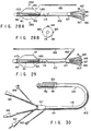
- FIG. 29 shows the intra-cavity applicator 102 incorporated in the medical apparatus.
- the intra-cavity applicator 102 is a modification of the applicator of the twentieth embodiment (FIGS. 28A and 28B). As shown in FIG. 29, the applicator 102 is characterized in that an RI catheter tube 191 made of fluororesin such as Teflon is mounted partly on the shaft 115 and partly on the outer surface of the balloon 182. The tube 191 has its closed distal end located at the distal end of the shaft 115 and mounted on the balloon 183. The proximal end of the tube 191 is located at the proximal end portion 107 of the applicator 102 and connected to a catheter guide 192.
- an RI catheter tube 191 made of fluororesin such as Teflon
- An RI catheter 185 can be inserted into the tube 191 via the catheter guide 192, no matter whether the balloon 182 is inflated or deflated.
- the catheter 185 is inserted into the tube 191 until the catheter 185 abuts on the closed distal end of the tube 191, whereby the distal end of the catheter 185 is located on the balloon 182.
- the RI catheter tube 191 has its distal end portion mounted on the outer surface of the balloon 182, and the RI catheter 185 is inserted in the tube 191.
- the shaft 115 to move the tube 191 to a position where the tube 191 faces the affected part.
- the radiation emitted from the RI catheter 185 can therefore be applied concentratedly onto any affected part present on the inner surface of the body cavity, as in the fourteenth embodiment.
- the intra-cavity applicator can enables a surgeon to perform both radiotherapy and thermotherapy with high efficiency.
- the RI catheter 185 can be easily inserted into the RI catheter tube 191, and a radiation source can be inserted into the body cavity through the RI catheter tube 191.
- FIG. 30 shows the intra-cavity applicator 102 incorporated in the medical apparatus.
- the intra-cavity applicator 102 is a modification of the applicator of the twenty-first embodiment (FIG. 29). As shown in FIG. 30, the applicator 102 is characterized in that an X-ray marker 201 opaque to X-rays is provided on the distal end portion of the RI catheter tube 191. To be more specific, the X-ray marker 201 is mounted on the outer surface of the balloon 182.
- This intra-cavity applicator 102 is used in the following way to treat a tumor in a body cavity of a patient.
- a surgeon first inserts the applicator 102 into the body cavity. Then, the surgeon determines the position of the tumor in the cavity, from an X-ray image of the interior of the body cavity. From the X-ray image the surgeon can accurately determine the position of the distal end portion of the applicator 102 since the X-ray marker 201 is quite visible in the X-ray image. He or she rotates the shaft 115 of the applicator 102 around its axis, thereby positioning the distal end portion of the applicator 102 at the tumor, and inserts a RI catheter 185 into the RI catheter tube 191.
- the surgeon can perform both hyperthermia and radiotherapy on the tumor.
- the the RI catheter 185 may be inserted into the RI catheter tube 191 before the applicator 102 is inserted into the body cavity.
- the RI catheter tube 191 has its distal end portion mounted on the outer surface of the balloon 182, and the RI catheter 185 is inserted in the tube 191, as in the twenty-first embodiment (FIG. 29).
- the radiation emitted from the catheter 185 can be applied to the tumor, merely by rotating the shaft 115 around its axis O 1 to make the tube 191 oppose the tumor.
- the radiation emitted from the RI catheter 185 can be applied concentratedly onto any affected part present on the inner surface of the body cavity, as in the fourteenth embodiment (FIG. 17 to 21).
- the intra-cavity applicator 102 can enables a surgeon to perform both radiotherapy and thermotherapy with high efficiency.
- the surgeon can accurately determines not only the position of the tumor but also the position of the distal end portion of the applicator 102 from an X-ray image of the body cavity. This is because the X-ray marker 201 provided on the distal end portion of the applicator 102 is clearly seen in the an X-ray image. It suffices for him or her to rotate the shaft 115 of the applicator 102 around its axis, to thereby position the distal end portion of the applicator 102 at the tumor. Once the distal end portion of the applicator 102 is so positioned, the radiation emitted from the RI catheter 185, which is inserted in the distal end portion of the applicator 102, is applied concentratedly onto the tumor.
- FIGS. 31A nd 31B show the intra-cavity applicator 102 provided in this medical apparatus.
- the intra-cavity applicator 102 shown in FIGS. 31A and 31B is a modification of the applicator 102 of the fourteenth embodiment (FIGS. 17 to 21).
- X-ray markers 211 and 212 are mounted on two distal end portions of the shaft 115. Both X-ray markers 211 and 212 are opaque to X rays.
- the first X-ray marker 211 indicates the position of the distal end of the radiation source passage 116 which is formed in the shaft 115 and which cannot be seen from outside.
- the second X-ray maker 212 indicates the position of a portion of the passage 116 which is proximal with respect to the distal end of the passage 116.
- the intra-cavity applicator 102 is used in the following way to treat a tumor in a body cavity of a patient.
- a surgeon inserts the applicator 102 into the body cavity.
- he or she determines the position of the tumor in the cavity, from an X-ray image of the body cavity.
- the surgeon can see the images of both X-ray markers 211 and 212 in the X-ray image.
- the surgeon rotates the shaft 115 of the applicator 102 around its axis, until the images of the X-ray markers 211 and 212 move to the image of the tumor.
- the shaft 115 is positioned, with the distal end portion of the radiation source passage 116 placed at the tumor.
- the surgeon inserts a radiation source 128 into the radiation source passage 116.
- the surgeon can then perform hyperthermia and radiotherapy simultaneously on the tumor.
- the radiation source 128 may be inserted into the passage 116 before the shaft 115 is inserted into the body cavity.
- the twenty-third embodiment can attain the same advantages as the twenty-second embodiment (FIG. 30).
- the X-ray image of the interior of the body cavity is clearer than in the case the applicator of the twenty-second embodiment is inserted into the body cavity. This is because the shaft 115 is coated with the X-ray markers over a smaller area than its counterpart of the twenty-second embodiment.
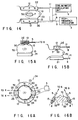
- FIGS. 32A and 32B A medical apparatus according to the twenty-fourth embodiment of this invention will be described with reference to FIGS. 32A and 32B.
- FIG. 32A shows the intra-cavity applicator 106 incorporated in the apparatus.
- an RI catheter tube 191 is mounted on the outer surface of the shaft 115 of the applicator 106 and extends along the shaft 115.
- This embodiment is characterized in that an X-ray marker 222 is provided on the distal end portion of a thin catheter 221 to be inserted into the RI catheter tube 191, as illustrated in FIG. 32B --not on the distal end of the RI catheter tube 191 as in the twenty-second embodiment (FIG. 30).
- the intra-cavity applicator 106 is used in the following way to treat a tumor in a body cavity of a patient.
- a surgeon first inserts the applicator 106 into the body cavity.
- he or she inserts the catheter 221 into the RI catheter tube 191.
- the surgeon determines the position of the tumor in the cavity and also the position of the X-ray marker 222, from an X-ray image of the interior of the body cavity. He or she rotates the shaft 115 of the applicator 106 around its axis, until he or she sees the marker 222 move to the tumor in the X-ray image.
- the surgeon pulls the catheter 221 from the RI catheter tube 191 and inserts an RI catheter 185 (i.e., a radiation source) into the RI catheter tube 191.
- an RI catheter 185 i.e., a radiation source
- the surgeon can perform hyperthermia and radiotherapy simultaneously on the tumor.
- the twenty-fourth embodiment can attain the same advantages as the twenty-second embodiment (FIG. 30). Further, the intra-cavity applicator 106 can be manufactured at a lower cost than those of the twenty-second and twenty-third embodiments since an X-ray marker need not be provided on any component as is required in the twenty-second and twenty-third embodiments. Still further, the X-ray image of the interior of the body cavity is clearer than in the case the applicators of the twenty-second and twenty-third embodiment are inserted into the body cavity, because the X-ray marker 222 on the distal end portion of the catheter 222 is very small.
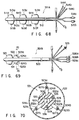
- FIGS. 33A to 33D show an intra-cavity applicator.
- the intra-cavity applicator of the twenty-fifth embodiment is a modification of the applicator 102 of the fourteenth embodiment (FIG. 7 to 21). It is characterized in that a graduation 231 is provided on that portion of the shaft 115 which opposes the radiation source passage 116 which is formed in the shaft 115 and which cannot be seen from outside.
- the radiation source passage 116 has a diameter D as shown in FIG. 33D.
- the intra-cavity applicator of the twenty-fifth embodiment is used in the following way to treat a tumor in a body cavity of a patient.
- a surgeon first inserts the applicator 106 into the body cavity.
- the surgeon inserts a radiation source into the radiation source passage 116. This done, he or she rotates the shaft 115 of the applicator around its axis, until he or she sees the desired position of the graduation 231 move to the tumor in the X-ray image, thereby positioning at the tumor the radiation source contained in the passage 116.
- the surgeon can then perform hyperthermia and radiotherapy simultaneously on the tumor.
- the the radiation source may be inserted into the passage 116 after the shaft 115 is rotated to locate the passage 116 at the tumor.
- the twenty-fifth embodiment can attain the same advantages as the twenty-third embodiment (FIGS. 31A and 31B). Additionally, the intra-cavity applicator can be manufactured at a lower cost than its counter-part of the twenty-third embodiment since no X-ray markers and no catheters are used to position the radiation source at the tumor.
- the graduation 231 may be an X-ray marker which is opaque to X rays.
- a surgeon use the intra-cavity applicator in the following manner to treat a tumor in a body cavity of a patient. At first, he or she inserts the shaft 115 of the applicator into the body cavity and insert the radiation source into the radiation source passage 116. Then, the surgeon determines the position of the tumor and also the position of the graduation 231, from an X-ray image of the interior of the body cavity. He or she rotates the shaft 115 around its axis, until the graduation 231 move to the tumor. The surgeon can then perform hyperthermia and radiotherapy simultaneously on the tumor.
- the the radiation source may be inserted into the passage 116 after the shaft 115 is rotated to locate the graduation 231 at the tumor. Since the graduation 231 is an X-ray marker, the surgeon can place the radiation source at the desired position in the body cavity, within a shorter time than he or she can do so with the intra-cavity applicator 102 of the twelfth embodiment.
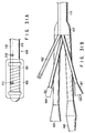
- FIG. 34 is a perspective view of the intra-cavity applicator 102 used in the medical apparatus
- FIG. 35 is a cross-sectional view of the shaft 115 of the applicator 102.
- the intra-cavity applicator 102 is a modification of its counterpart of the fourteenth embodiment (FIGS. 17 to 21).
- the shaft 115 of the applicator 102 has coaxial radiation source passage 116 (or a central lumen) and four lumina 117 to 120.
- the passage 116 is coaxial with the shaft 115, whereas the lumina 117 to 120 extend parallel to the axis of the shaft 115.
- the lumina 117, 118, 119 and 120 are used as cooling water supplying passage, cooling water discharging passage, temperature sensor passage and electrode cable passage, respectively.
- the lumina 117 to 120 may take positions in the shaft 115, which are different from those shown in FIG. 35, so long as they extend through the shaft 115 over the entire length thereof. Furthermore, the radiation source passage 116 need not be coaxial in its entirety with the shaft 115, provided that at least its distal end part is set in true axial alignment with the shaft 115.
- the radiation source passage 116 need not extends to the very distal end of the shaft 115 as shown in FIG. 34. It may extend through the shaft 115 only to the balloon 126, because it suffices to guide a radiation source 128 to any part of the shaft 115 that is surrounded by the balloon 126. In this case, too, at least the distal end portion must be coaxial with the shaft 115.
- the radiation source 128 is automatically set at the distal end of the passage 116 when a radiation source tube 112 is inserted into the passage 116 until it abuts on the closed end (i.e., the distal end) of the passage 116. So set, the radiation source 128 emits radiation uniformly in a plane which is perpendicular to the axis of the shaft 115.
- a surgeon operates the applicator 102 to treat a tumor in a body cavity of a patient.
- the surgeon inserts the applicator 102 into the body cavity.
- the radiotherapy controller 113 which is provided outside the operating room 103 and which is connected to the radiotherapeutic device 110, supplying the radiation source 128 to the distal end portion of the passage 116 as shown in FIG. 35, since the radiation source tube 112 is inserted in the passage 116.
- the twenty-sixth embodiment is advantageous in several respects.
- the apparatus 101 enables the surgeon to treat an affected part of a patient, such as cancer, with high efficiency, since the hyperthermia device 109 and the radiotherapeutic device 110 can be operated to perform hyperthermia and radiotherapy at the same time.
- the radiation emitted from the source 128 can be applied uniformly onto an affected part present on the entire inner surface of a body cavity, because the radiation source 128 is coaxial with the shaft 115. Not only hyperthermia but also radiotherapy can be applied evenly on the affected part, thus treating the affected part effectively.
- the surgeon needs to insert the applicator 102 into the body cavity, but only once, in order to perform radiotherapy and hyperthermia on cancer in the body cavity, without making side effect on any part of the patient. This is because the applicator 102 has the high-frequency electrode 125 and because the radiation source tube 112 inserted in the passage 116 of the shaft 115 contains the radiation source 128.
- the radiation source 128 is surrounded by the high-frequency electrode 125, it would not distort the temperature distribution which the hyperthermia achieves in the affected part.
- the applicator 106 can be disinfected easily.
- the shaft 115 can be made more easily than the passage 116 is closed at the distal end. Extending through the shaft 115 over the entire length thereof, the passage 116 can serve some purposes other than to guide the radiation source 128 into the body cavity. More specifically, the passage 116 can be used to guide a wire or an endoscope into the body cavity and to supply air into the body cavity.
- FIG. 36 is a sectional view of the distal end portion of the intra-cavity applicator incorporated in the medical apparatus.
- This intra-cavity applicator is a modification of the applicator 102 of the twenty-sixth embodiment (FIGS. 34 and 35). It is characterized in that a smoothing layer 232 made of, for example, Teflon, is provided on the inner surface of the radiation source passage 116 made in the shaft 115. The friction between the layer 232 and the radiation source tube 112 inserted in the passage 116 is low, and the tube 112 can be smoothly guided through the passage 116 even if it is comparatively long. Without the smoothing layer 232, it would be difficult for a surgeon to insert the tube 112 deep into the passage 116, particularly so if the shaft 115 is made of silicone or the like.
- the smoothing layer 232 facilitates the insertion of the radiation source tube 112 through the radiation source passage 116.
- the radiation source tube 112 may be replaced by a Teflon tube which has a low friction coefficient with respect to the inner surface of the passage 116.
- the Teflon tube can be smoothly inserted, deep into the radiation source passage 116.
- FIG. 37 is a sectional view of the proximal end portion 107 of the intra-cavity applicator incorporated in a medical apparatus.
- the intra-cavity applicator is a modification of the applicator 102 of the twenty-sixth embodiment (FIGS. 34 and 35).
- the radiation source passage 116 has its diameter gradually increasing toward its proximal end 116a.
- the inner circumferential surface 233 of the passage 116 flares toward the proximal end 116a.
- a syringe 234 can be easily inserted into the flaring proximal end portion of the passage 116 to apply a lubricating agent into the radiation source passage 116.
- the syringe 234 may be squeezed to apply liquid medicine into the passage 116 and may be released to draw air from the passage 116.
- the twenty-ninth embodiment of the invention which is also a medical apparatus, will be described, with reference to FIGS. 38A, 38B and 38C.
- FIG. 38A is an overall view of the medical apparatus. As seen from FIG. 38A, the apparatus has an intra-cavity applicator 241.
- the applicator 241 comprises an insertion section 242 and a proximal section 243.
- the insertion section 242 is designed for insertion into the body cavity.
- the proximal section 243 is connected to the proximal end of the insertion section 242.
- the insertion section 242 has a shaft 244 made of soft material such as silicone rubber.
- the shaft 244 has two thermotherapeutic electrodes 245a and 245b, the former located in front of the latter.
- the electrodes are mounted on the outer surface of the distal end portion of the shaft 244.
- Two balloon 246a and 246b made of silicone rubber or the like are mounted on the distal end portion of the shaft 244, covering the electrodes 245a and 245b, respectively.
- Each of the electrodes 245a and 245b is a tin-plated copper wire wound around the shaft 244.
- Two temperature sensors 247a and 247b are mounted on the outer surface of the front balloon 246a.
- two temperature sensors 247c and 247d are mounted on the outer surface of the rear balloon 246b.
- the shaft 244 has five lumina 248 to 252. Of these lumina, the central one is a radiation source passage 248 which is coaxial with the shaft 244. The remaining four lumina 249 to 252 extend through the shaft 244, parallel to the passage 248.
- the lumina 249, 250, 251 and 252 are used as cooling water supplying passage, cooling water discharging passage, temperature sensor passage and electrode cable passage.
- the cooling water used is, for example, purified water.
- the chain-line circle indicates the outline either balloon assumes when fully inflated.
- the inner surface of the radiation source passage 248 is covered with a layer 253 made of fluororesin or the like and having a low friction coefficient.
- the passage 248 is closed at the distal end portion of the shaft 244 as illustrated in FIG. 38A. Instead, the passage 248 may extends throughout the shaft 244 and open at the distal end thereof.
- the shaft 244 has holes 254a, 254b, 255a and 255b in the outer circumferential.
- the holes 254a and 254b connects the interior of the front balloon 246a to the cooling water supplying passage 249 and the cooling water discharging passage 250.
- the holes 255a and 255b connects the interior of the rear balloon 246b to the passages 249 and 250.
- the applicator 241 has at its proximal end portion 243 a radiation source guide 257, a coolant inlet connector 258, a coolant outlet connector 259, cable connectors 260 and 261, and an RF connector 262.
- the guide 257 is used to guide a radiation source 256 into the radiation source passage 248.
- the coolant inlet connector 258 is coupled to the distal end of the cooling water supplying passage 249.
- the coolant outlet connector 259 is connected to the distal end of the cooling water discharging passage 250.
- the cable connectors 260 and 261 are provided to connect signals cables to the temperature sensors 247a to 247d so that the signals generated by the sensors may be supplied through the signal cables.
- the RF connector 262 is provided to connect an RF power cable to the thermotherapeutic electrodes 245a and 245b so that RF (radio-frequency) power may be supplied to the electrodes 245a and 245b.
- a water supplying tube (not shown) and a water discharging tube (not shown) are connected to the inlet connector 258 and the outlet connector 259, respectively.
- Signal lines 263 extend through the temperature sensor passage 251 and are connected to the temperature sensors 247a to 247d, and power supply lines 264 extend through the electrode cable passage 252 and are connected to the thermotherapeutic electrodes 245a and 245b.
- a radiation source guide tube 265 is inserted into the radiation source guide 257.
- the tube 265 is connected at its proximal end to the radiation source supplying/recovering port of a radiation source remote-controller 266.
- the tube 265 has its distal end portion inserted via the radiation source guide 257 into the radiation source passage 248.
- the radiation source 256 introduced into the applicator 241 is positioned between the thermotherapeutic electrodes 245a and 245b.
- the surgeon connects the water supplying tube, water discharging tube, signal cables and RF power cable of a hyperthermia device (not shown) of the type shown in FIG. 19 to the inlet connector 258, outlet connector 259, sensor connectors 260 and 261.
- the surgeon inserts the insertion section 242 of the applicator 241 into a tubular cavity 267 of the patient.
- the surgeon attaches the electrode of ⁇ an extracorporeal applicator (not shown) of the type shown in FIG. 19 to the patient, at a position opposing to the thermotherapeutic electrodes 245a and 245b, and connects the electrode to the hyperthermia device. In this condition, the surgeon can perform thermotherapy on the affected part resent in the body cavity.
- the surgeon positions the insertion section 242 of the intra-cavity applicator 241 in the tubular cavity 267, as is shown in FIG. 38B. Namely, the insertion section 242 is positioned such that a tumor 268 developing on the inner surface of the cavity 267 is located between the balloons 246a and 246b both contacting the inner surface of the cavity 267.
- the surgeon inserts the radiation source guide tube 265 connected to the radiation source remote-controller 266 is inserted into the radiation source passage 248 via the radiation source guide 257. Further, he or she places the radiation source 256 contained in the applicator 241, at a position between the thermotherapeutic electrodes 245a and 245b as illustrated in FIG. 38B. In this condition, the surgeon can perform radiotherapy on the tumor 268.
- the radiation source 256 used is, for example, 192 Ir ( ⁇ 1.1 x 3.3 mm, 370 GBq). It is inserted into the radiation source guide tube 265 and thereby introduced into the tubular cavity 267, as the surgeon operates the radiation source remote-controller 266, moving an operation wire or supplying air into the guide tube 265.
- thermotherapy is conducted, usually for about one hour by applying electromagnetic waves to the tumor 258 from the thermotherapeutic electrodes 245a and 245b. The surgeon can therefore perform radiotherapy, while performing the thermotherapy, by using the intra-cavity applicator 241.
- A(R) K ⁇ 1/R 2 ⁇ B(R) where K is a constant and R is the distance between the source of radiation and the tumor.
- the distribution of radiation, K ⁇ 1/R 2 sharply decreases with the square of the distance R. So does the dose of radiation, B(R).
- the effect of radiation is said to decrease very much when the distance R is about 5 mm or more.
- the decrease in the organism effect A(R) should be avoided to successfully perform thermotherapy and radiotherapy at the same time.
- that region of the tumor which can be heated by the electromagnetic waves from the electrodes 245a and 245b must be located very close to that region of tumor to which the radiation can be applied from the source 256.
- the two electrodes 245a and 245b and the radiation source 256 need to have this specific positional relationship in order to attain sufficient effect A(R).
- the source 256 set in the shaft 244 is not surrounded by the balloon 246a or the balloon 246b in which coolant is circulated, and there is nothing, but the shaft 244, that blocks the radiation the source 256 emits toward the tumor 268.
- the radiation source 256 is located quite near the tumor 268. Hence, the radiation source 256 fully serves to accomplish effective radiotherapy on the tumor 268.
- the tumor 268 to which the radiation is applied can be heated uniformly by the electromagnetic waves emitted from the electrodes 245a and 245b, provided that the thermotherapeutic electrodes 245a and 245b are spaced apart but by a relatively short distance of 50 mm or less.
- the medical apparatus With the medical apparatus according to the present embodiment, it is possible to conduct radiotherapy with high efficiency by applying the radiation from the source 256 to the tumor 268, while heating the affected part uniformly by applying the electromagnetic waves thereto from the electrodes 245a and 245b.
- the surgeon can therefore treat the tumor effectively within a short period of time, without inflicting much pain on the patient.
- the radiation source guide tube 265 is automatically set at a desired position with respect to the tumor 268. This helps to increase the safety of therapy.
- thermotherapy e.g., hyperthermia
- radiotherapy can be uniformly applied on the tumor 268, effectively treating the tumor 268.
- FIG. 39 shows the distal end portion of the shaft 244 of the intra-cavity applicator 241 incorporated in the medical apparatus.
- the intra-cavity applicator is a modification of the applicator 241 of the twenty-ninth embodiment (FIGS. 38A to 38C).
- a thin hollow rod 271 is connected to the distal end of the shaft 244.
- a balloon 272 made of silicone rubber or the like is mounted on the rod 271, covering the both electrodes 245a and 245b.
- the distal end of the shaft 244 has two holes 275 and 276.
- the hole 275 connects the interior of the balloon 272 to the cooling water supplying passage 249 provided in the shaft 244.
- the hole 276 connects the interior of the balloon 272 to the cooling water discharging passage 250 provided in the shaft 244.
- a radiation source 256 is set within the that portion of the hollow rod 271 which is surrounded by neither the electrode 245a or the electrode 245b.
- the radiation source 256 in the shaft 242 is not surrounded by neither balloon, there is nothing, but the wall of the rod 271, that blocks the radiation the source 256 emits toward a tumor.
- the intra-cavity applicator 241 must have but less temperature sensors and less coolant passages than the applicator 241 of the twenty-ninth embodiment. Thus, the applicator 241 can be made thinner than the applicator 241.
- the distance between the tumor and the radiation source 256 is increased to a comparatively large value.
- the radiation is distributed more desirably, in the radial direction of the intra-cavity applicator 241.
- the dose of radiation changes but moderately in the direction of depth of the annular tumor, whereby the radiation reaches a sufficient depth in the tumor.
- FIG. 40 illustrates the intra-cavity applicator of the apparatus.
- this applicator is characterized in two respects. First, a tube 281 made of fluororesin and having a low frictional coefficient is fitted in the distal end portion of the radiation source passage 248 which is made in the shaft 244 (not shown) and which is coaxial therewith. The tube 281 has a length d of about 50 mm at most. Secondly, a tube 282 made of material opaque to radiation is fitted in the other portion of the passage 248 and mounted on the radiation source guide 257.
- the tube 282 fitted in the passage 248, except in the distal portion thereof, is opaque to radiation, the radiation emitted from the radiation source 256 does not leak from the applicator until the source 256 is guided into the distal end portion of the passage 248. In other words, the radiation would not be applied, but from the distal end portion of the passage 248. This ensures helps to increase the safety of therapy.
- a medical apparatus according to the thirty-second embodiment of the present invention will be described with reference to FIG. 41.
- the thirty-second embodiment is a modification of the twenty-ninth embodiment (FIGS. 38A to 38C).
- the intra-cavity applicator 241 of the thirty-second embodiment has a connector 291 connected to the proximal end of the radiation source passage 248.
- the connector 291 can be coupled to the radiation source remote-controller 266 for controlling a radiation source 256.
- the connector 291 is replaced by another which is shaped so as to be coupled to the remote-controller of the different type.
- the shaft 244 can be thinner, having a diameter less than its counterpart of the twenty-ninth embodiment by about 1 to 1.5 mm, and can be more smoothly inserted into a body cavity. Since no radiation source guide tube is required, the radiation source would not be displayed with respect to the passage 248, unlike in the case where a guide tube is used. This helps to enhance the safety of therapy.
- FIGS. 42 and 43 illustrates a medical apparatus according to the thirty-third embodiment of the present invention, more precisely the intra-cavity applicator 102 of the medical apparatus.
- the intra-cavity applicator 102 is similar to its counterpart of the twenty-sixth embodiment (FIGS. 34 and 35). As illustrated in FIGS. 42 and 43, two hollow cylinders 301 and 302 made of lead are mounted on the distal end portion of the shaft 115 of the applicator 102, for preventing radiation from leaking from the shaft 115.
- the cylinders 301 and 302 are spaced apart along the axis of the shaft 115.
- a high-frequency electrode 125 is wound around that portion of the shaft 115 located between the cylinders 301 and 302.
- a balloon 126 is mounted on the distal end portion of the shaft 115, covering both hollow cylinders 301 and 302.
- the applicator 102 has at its proximal end portion 107 a water inlet connector 303, a water outlet connector 304, a sensor connector 305, an electrode cable connector 306, and a radiation source guide 307.
- the water inlet connector 303 is connected to the water supplying passage 117 made in the shaft 115.
- the water outlet connector 30 4 is connected to the water discharging passage 118 formed in the shaft 115.
- the sensor connector 305 is connected to the temperature sensor cable 123 extending through the temperature sensor passage 119 formed in the shaft 115.
- the electrode cable connector 306 is connected to the electrode cable 124 extending in the electrode cable passage 120 provided in the shaft 115.
- the radiation source guide 307 is provided to guide a radiation source tube 112 into the radiation source passage 116 formed in the shaft 115.
- the surgeon insert the applicator 102 into the body cavity such as the esophagus, rectum, or vagina, until the distal end portion of the applicator 102 reaches the affected part in the body cavity. This done, he or she supplies cooling water into the balloon 126, inflating the balloon 126. The distal end portion of the applicator 102 is thereby held in place in the body cavity. Thereafter, the surgeon controls the high-frequency electrode 125 in accordance with the temperature the sensor 127 has detected. That is, the surgeon supplies a high-frequency current to the electrode 125 and stops supplying the current thereto, thereby keeping the affected part at 42 to 43°C.
- the surgeon inserts a radiation source 128 from the radiation source guide 307 into the radiation source passage 116 through the radiation source tube 112.
- the radiation emitted from the source 128 set in the passage 116 is applied onto the affected part, which is subjected to radiotherapy. Since the hollow cylinders 301 and 302 are made of lead and hence opaque to radiation, the radiation is emitted from that portion of the shaft 115 which is located between the cylinders 301 and 302.
- the thirty-third embodiment enables the surgeon to perform thermotherapy and radiotherapy, either simultaneously or sequentially. Additionally, the radiation can be applied onto only the affected part since the cylinders 301 and 302 prevent the radiation from being applied to any part other than the affected part.
- the hollow cylinders 301 and 302 may be located outside the balloon 126.
- the cylinders 301 and 302 may be replaced by strips opaque to radiation. They may be loosely mounted on the shaft 115 so that they may slide along the shaft 115 to change the position where the radiation is shielded. Further, they may be made of iron, lead glass or tungsten, instead of lead.
- FIGS. 44 and 45 show a large extracorporeal applicator 321 which is designed for use in combination with the intra-cavity applicator 102 of the twenty-sixth embodiment (FIGS. 34 and 35).
- the extracorporeal applicator 321 is wrapped around a patient, as illustrated in FIG. 44.
- the applicator 321 may be wrapped around the patient's chest to heat the esophagus. It may be wrapped around the patient's waist to heat the rectum or the vagina.
- the extracorporeal applicator 321 comprises a main body 321a, a plate-shaped extracorporeal electrode 322, a lead plate 323, and a bolus 324.
- the electrode 322 is embedded in the main body 321a.
- the lead plate 323 is also embedded in the main body 321a, surrounding the extracorporeal electrode 322.
- the bolus 324 is connected to the main body 321a. Connected to the bolus 324 are a water supplying tube 325 and a water discharging tube 326. Through the tubes 325 and 326 cooling water is supplied into and discharged from the bolus 324, circulating therein.
- the extracorporeal applicator 321 When the extracorporeal applicator 321 is wrapped around the patient, radiation is applied to an affected part only, not to any other part. For example, when the applicator 321 is wrapped around the patient's chest as shown in FIG. 44, to apply radiation to the esophagus, it prevents application of radiation to any other organ such as the brain.
- the extracorporeal applicator 321 prevents any part other than an affected part from being exposed to radiation.
- the intra-cavity applicator 102 of the twenty-sixth embodiment (FIGS. 34 and 35)
- it enables a surgeon to conduct thermotherapy and radiotherapy, simultaneously or sequentially.
- FIG. 46 illustrates a medical apparatus which is the thirty-fifth embodiment of the present invention. More precisely, it is a partly sectional, perspective view of the intra-cavity applicator 102 of the medical apparatus.
- This intra-cavity applicator 102 is a modification of its counterpart of the twenty-sixth embodiment (FIGS. 34 and 35). As seen from FIG. 46, the applicator 102 is characterized in that a strip-shaped high-frequency electrode 331 made of electrically conductive rubber is wound around the distal end portion of the shaft 115 which is made of silicone.
- the applicator 102 has at its proximal end portion 107 a radiation source guide 116a, a water inlet connector 332, a water outlet connector 333, a sensor connector 334, an electrode cable connector 335.
- the radiation source guide 116a is provided to guide a radiation source tube 112 into the radiation source passage 116 formed in the shaft 115.
- the water inlet connector 332 is connected to the water supplying passage 117 made in the shaft 115.
- the water outlet connector 333 is connected to the water discharging passage 118 formed in the shaft 115.
- the sensor connector 334 is connected to the temperature sensor cable 123 extending through the temperature sensor passage 119 formed in the shaft 115.
- the electrode cable connector 335 is connected to the electrode cable 124 extending in the electrode cable passage 120 provided in the shaft 115.
- a surgeon inserts the applicator 102 with the balloon 126 deflated, into the body cavity.
- the surgeon then supplies cooling water into the balloon 126 from the water inlet connector 332 through the water supplying passage 117.
- the balloon 126 is thereby inflated until it touches the inner surface of the body cavity, whereby the distal end portion of the applicator 102 is held in place in the body cavity.
- the cooling water circulates in the balloon 126.
- a current is supplied between the electrode 331 of the intra-cavity applicator 102 and the electrode of an extracorporeal applicator (not shown) of the type shown in FIGS. 45A and 45B which is wrapped around the patient.
- the surgeon inserts a radiation source 128 from the radiation source guide 116a into the radiation source passage 116 through the radiation source tube (no shown).
- the radiation emitted from the source 128 set in the radiation source passage 116 is applied onto the affected part, which is subjected to radiotherapy.
- the high-frequency electrode 331 is made of electrically conductive rubber, the radiation can pass the electrode 331 more readily than through an ordinary electrode which is made of metal.
- the electrode 331 serves to enhance the efficiency of applying radiation to the affected part. It therefore enables the surgeon to perform radiotherapy in the same condition, either singly or in combination with thermotherapy.
- FIG. 47 shows the distal end portion of the intra-cavity applicator 102 incorporated in a medical apparatus according to the thirty-sixth embodiment of the present invention.
- an electrode 341 which is a tin-plated wire is wound around the distal end portion of the shaft 115 of the intra-cavity applicator 102, thereby forming a coil.
- the middle part 341a of the electrode 341 is made of turns sparsely arranged, whereas both end parts 341b and 341c are constituted by turns densely arranged.
- the electrode 341 is a coil made of a tin-plated wire which is opaque to radiation, radiation can emanate outwards through the middle part 341a of the electrode 341, which is formed of sparsely arranged turns. On the other hand, the radiation cannot pass through the end parts 341b and 341c which are formed of densely arranged turns. Hence, as in the thirty-third embodiment (FIGS. 42 and 43), any part other than an affected part can be protected from radiation exposure.
- FIG. 48 shows the distal end portion of the intra-cavity applicator 102 incorporated in a medical apparatus according which is the thirty-seventh embodiment of the invention.
- An electrode 351 which is a mesh of tin-plated wires is wound around the distal end portion of the shaft 115 of the applicator as in the twenty-sixth embodiment.
- a balloon 126 is mounted on the distal end portion of the shaft 115, covering the mesh electrode 351.
- the mesh electrode 351 consists of a coarse middle part 351a, a dense front end part 351b and an equally dense rear end part 351c.
- the middle part 351a is located in the middle part of the balloon 126, whereas the end parts 351b and 351c are located in the end parts thereof. Radiation can therefore be emitted outwards through the middle part 351a of the electrode 351 and cannot emanate through the dense end parts 351b and 351c. Any part other than an affected part can be protected from radiation exposure as in the thirty-sixth embodiment (FIG. 47).
- FIG. 49 is a cross-sectional view of the intra-cavity applicator 102 provided in a medical apparatus which is the thirty-eighth embodiment of the present invention.
- This intra-cavity applicator 102 is a modification of its counterpart of the twenty-sixth embodiment (FIGS. 34 an 35).
- the applicator 102 is characterized in that four radiation source passages 361a to 361d are made in the shaft 115 as seen from FIG. 49. These passages 361a to 361d are equidistant from the axis of the shaft 115 and spaced apart at regular intervals along the circumference of the shaft 115.
- each radiation source 128 is inserted into the passages 361a to 361d through four radiation source tubes (not shown). Radiation is emitted from the sources 128 and distributed virtually uniformly in a plane which is perpendicular to the axis of the shaft 115.
- FIG. 50A shows the distal end portion of the intra-cavity applicator 102 used in the medial apparatus
- FIG. 50B is a cross-sectional view of the applicator 102.
- the intra-cavity applicator is a modification of the applicator 102 of the twenty-sixth embodiment (FIGS. 34 and 35).
- a thin shaft 371 protrudes from the distal end of the shaft 115, and a tip member having the same diameter as the shaft 115 is connected to the distal end of the thin shaft 371.
- a thermotherapeutic electrode 125 is wound around the thin distal end portion 371.
- the shaft 115 has four radiation source passages 381a to 381d which open at the distal end.
- Four connection tubes 382a to 382d are connected at proximal end to the distal ends of the radiation source passages 381a to 381d.
- the tubes 382a to 382d extend between the shaft 115 and the tip member, parallel to the-axis of the thin shaft 371.
- the tubes 382a to 382d are spaced apart at regular intervals along the circumference of the shaft 115.
- a balloon 126 is mounted on the shaft 115, with its front and rear ends fastened to the tip member and the distal end of the shaft 115, respectively.
- a water supplying passage 117, a water discharging passage 118, a temperature sensor passage 119, and an electrode cable passage 120 are formed in both the shaft 115 and the thin shaft 371, extending parallel to the identical axis of the shaft 115 and the thin shaft 371.
- the thin shaft 371 has four holes 117b to 120b in its circumferential surface, which communicate with the passages 117 to 120.
- radiation sources 128 have been inserted into the connection tubes 382a to 382d via radiation source tubes (not shown) and the radiation source passages 381a to 381d. Radiation is emitted from the sources 128, distributed substantially uniformly in a plane perpendicular to the axis of the shaft 115, whereby radiotherapy is carried out.
- FIG. 51 shows the thermotherapeutic applicator 401 used in the medical apparatus.
- FIG. 52 is a cross-sectional view of the applicator 401.
- FIGS. 53A to 53E are diagrams explaining how radiation is distributed from the thermotherapeutic applicator 401.
- the thermotherapeutic applicator 401 comprises a proximal section 402, a shaft 403 and a distal section 404.
- the shaft 403 has multi-lumen structure. That is, as shown in FIG. 52, five radiation source passages 405, a water supplying passage 405a, a water discharging passage 405b, a temperature sensor passage 405c and an electrode cable passage 405d are formed in the shaft 403.
- the center radiation source passage 405 is coaxial with the shaft 403.
- the passages 405a, 405b, 405c and 405d extend parallel to the axis of the shaft 403.
- Four more radiation source passages 405 are formed in the shaft 403, extending parallel to the axis thereof and located among the passages 405a to 405d as shown in FIG. 52.
- Five radiation source tubes 406 are inserted into the radiation source passages 405, respectively.
- a high-frequency electrode 407 which is a wire, is wound around the distal section 404 of the shaft 403. The electrode is used to conduct thermotherapy.
- a balloon 413 is fastened to the distal section 404, covering the high-frequency electrode 407.
- Radiation sources 408 are inserted into the radiation source tubes 406 inserted in the radiation source passages 405.
- the sources 408 can be located in the passages 405, surrounded by the high-frequency electrode 407. As shown in FIG. 51, the radiation source passages 405 are opened at the distal end of the shaft 403. Nonetheless, the passages 405 may be closed at the distal end of the shaft 403.
- the water supplying passage 405a is connected to a water supplying tube 409, and the water discharging passage 405b to a water discharging tube 410.
- a temperature sensor cable 411 extends through the temperature sensor passage 405c, and an electrode cable 412 extends through the electrode cable passage 405d.
- Cooling water can flow into the balloon 413 through the water supplying passage 405a and from the balloon 413 through the water discharging passage 405b, to circulate within the balloon 413.
- the temperature sensor cable 411 is led outside at the rear end of the balloon 413 and connected to a temperature sensor 414, which is mounted on the outer surface of the balloon 413.
- the electrode cable 412 is led out from the shaft 403 and connected to the electrode 407, within the balloon 413.
- thermotherapeutic applicator 401 it will be explained how a surgeon use the thermotherapeutic applicator 401 to an affected part present in a patient's body cavity.
- the applicator 401 is used an operating room of the type shown in FIG. 19, which is electromagnetically shielded.
- the surgeon connects the applicator 401 to a hyperthermia device (not shown) of the type shown in FIG. 19. He or she then evacuates the water supplying tube 409 and the water discharging tube 410. Cooling water is thereby drawn from the balloon 413, deflating the balloon 413.
- the surgeon inserts the applicator 401 into the patient's body cavity.
- the radiation source tube 406 is inserted into the passage 405, either before or after the insertion section of the applicator 401 is inserted into the body cavity.
- thermotherapeutic applicator 401 After the insertion section of the applicator 401 is inserted into the body cavity, cooling water is supplied into and circulated in the balloon 413. The balloon 413 is thereby inflated and comes into contact with the inner surface of the body cavity. As a result, the distal end portion of the thermotherapeutic applicator 401 is held steadfastly in the body cavity.
- the surgeon starts performing thermotherapy.
- the surgeon steps out of the operating room.
- the surgeon operates a radiotherapy controller of the type shown in FIG. 19.
- the controller is connected to the radiotherapeutic device installed in the operating room.
- the radiation sources 408 are thereby inserted from the radiotherapeutic device into the radiation source tubes 406 which are inserted in the body cavity.
- the sources 408 are placed in the distal section 404 of the applicator 401 because the tubes 406 are inserted in the passages 405 of the applicator 401.
- the radiation sources 408 set in the passages 405 emits radiation, which is applied onto the affected part present in the patient's body cavity. Radiotherapy is thus conducted on the affected part.
- thermotherapeutic applicator 401 had only one radiation source passage 405, the radiation emitted from the applicator 401 would extend in all directions as shown in FIG. 53A, in a spherical space whose center is the radiation source 408 set in the thermotherapeutic applicator 401.
- the distribution of radiation emitted from the applicator 401 is determined by the position and size of the radiation source 408.
- the shaft 403 of the applicator 401 has five radiation source passages 405.
- the surgeon can inserts one to five radiation source tubes 406 into selected one or ones of the radiation source passages 405, in accordance with the shape, size and position of the affected part he or she is going to treat.
- the first radiation source passage 405 is coaxial with the shaft 403, whereas the remaining four source passages 405 are equidistant from the axis of the shaft 403 and spaced apart at regular intervals along the circumference of the shaft 403.
- the radiation they emit is distributed uniformly in a circular plane which is perpendicular to the axis of the applicator 401 as is illustrated in FIG. 53B.
- the radiation applied from the applicator 401 is five times as intense as in the case where only one radiation source 408 is set in the thermotherapeutic applicator 401.
- a radiation source 408 is inserted in one of the four radiation source passage 405 which extend parallel to the axis of the shaft 403, as shown in FIG. 53C. Then, the radiation emitted from the source 408 is distributed in a circular plane which is perpendicular to the axis of the applicator 401 and whose center is the source 408, not the axis of the shaft 403.
- This specific distribution of radiation is desirable to treat, for example, cancer developing on a limited region of the inner surface of the body cavity. So distributed, the radiation is applied to the cancer only. This makes effective radiotherapy possible.
- radiation sources 408 are inserted in three adjacent ones of the radiation source passage 405 which extend parallel to the axis of the shaft 403, as shown in FIG. 53D.
- the radiation the sources 408 emit overlap and are distributed in the axial direction of the shaft 403.
- radiation can be distributed in a way desirable for treating an affected part by inserting radiation sources 408 into selected ones of the radiation source passages 405.
- two or more radiation sources 408 may be located in the radiation source passages 405 and displaced from one another in the axial direction of the applicator 401, as is shown in FIG. 53E.
- the radiation is distributed in an elliptical region which extends along the thermotherapeutic applicator 401. If the radiation thus distributed is less intense than desired, it suffices to insert more radiation sources 408 into the passages 405.
- thermotherapeutic applicator 401 is advantageous in the following respects.
- radiation sources 408 can be placed in any selected passage 405 and at any desired position along the axis thereof, because the shaft 403 has a plurality of radiation source passages 405. As a result, the radiation can be distributed in the following three patterns:
- the dose of the radiation emitted from the applicator 401 can be increased, if necessary, merely by inserting more radiation sources 408 into the passages 405. Once the dose is thus increased, the time required to complete the radiotherapy can be shortened. (Generally, the amount of radiation a source emits decreases with time. If only one radiation source is used, it must keep emitting radiation until the total amount of radiation emitted becomes adequate.)
- any radiation source 408 placed in the applicator 401 would not distort the temperature distribution which the hyperthermia achieves in the affected part. This is because the radiation source 408 is surrounded by the high-frequency electrode 407, Furthermore, the radiation source tubes 406 would not slips out of the applicator 401, provided that the radiation source passages 405 are closed at their distal ends. This ensures the safety of therapy.
- the passages 405, if opening at distal end, can be used for guiding an endoscope or an medical instrument into the body cavity, so that an affected part in the cavity may be observed and treated.
- a radiation source 408 is inserted into the first passage 405 coaxial with the shaft 403 of the applicator 401, the radiation it emits will be uniformly distributed in a circular plane whose center is on the axis of the shaft 403, as in the twenty-sixth embodiment.
- FIG. 54 is a cross-sectional view the thermotherapeutic applicator incorporated in a medical apparatus according to a forty-first embodiment of the invention.
- thermotherapeutic applicator is differs from its counterpart of the fortieth embodiment (FIGS. 51 and 52 and FIGS. 53A to 53E) in the structure of the shaft 403.
- the shaft 403 has eight radiation source passages 405 in the near-surface region of its distal section 404.
- the passages 405 extends parallel, located at the same distance from the axis of the shaft 403 and equally spaced along the circumference.
- a water supplying passage 405a, a water discharging passage 405b, a temperature sensor passage 405c and an electrode cable passage 405d are formed in the distal section 404 of the shaft 403, surrounded by the radiation source passages 405.
- the radiation source passages 405 need not be located at the same distance from the axis of the shaft 403 and equally spaced along the circumference.
- the number of passages 405 provided is not limited to eight.
- thermotherapeutic applicator is used in the same way as the applicator of the fortieth embodiment, except that a surgeon can use the passages 405 in more combinations and can set radiation sources in more possible positions, in accordance with the size, shape and position of an affected part he or she is going to treat.
- a surgeon can use the passages 405 in more combinations and can set radiation sources in more possible positions, in accordance with the size, shape and position of an affected part he or she is going to treat.
- the radiation sources are placed in all passages 405 provided, the radiation emitted from the sources is distributed uniformly in a circular plane perpendicular to the axis of the shaft 403. In this case, the radiation is effectively applied to cancer developing on the entire inner surface of the body cavity.
- radiation sources when radiation sources are placed in all passages 405, radiation can be applied to the cancer in a greater amount so that the cancer may be treated more effectively within a shorter time than by means of the thermotherapeutic applicator 401 of the fortieth embodiment.
- FIGS. 55 to 57 A medical apparatus according to the forty-second embodiment of the present invention will be described, with reference to FIGS. 55 to 57.
- This embodiment differs from the fortieth embodiment (FIGS. 51 and 52, FIGS. 53A to 53E) and the forty-first embodiment (FIG. 54) in the structure of the shaft 403 of the thermotherapeutic applicator 401.
- three radiation source passages 405 are provided side by side in a part of the near-surface region of the distal portion of the shaft 403.
- a mark 432 is provided on the proximal section 402 of the applicator 401, indicating the position of the radiation source passages 405.
- the applicator 401 of the forty-second embodiment is suitable for use in treating cancer developing in a limited region on the inner surface of a body cavity.
- a surgeon inserts the applicator 401 into the body cavity. He or she then rotates the applicator 401 until the mark 432 comes to face the cancer.
- the radiation source passages 405 formed in the shaft 403 of the applicator 401 are thereby made to oppose the cancer.
- the positions the passages 405 take with respect to the cancer and the number of radiation sources 408 to be set in the passages 405 are changed in accordance with the size of the cancer.
- the sources 408 are used in small numbers to distribute radiation in a relatively small part of the inner surface of the body cavity. Conversely, it the cancer extends a long distance along the circumference of the cavity, the sources 408 are used in great numbers to distribute radiation in a comparatively large part of the inner surface of the body cavity.
- the forty-second embodiment can apply radiation to the cancer developing on that limited region of the inner surface of the body cavity, not to the normal tissues present on the other region of the inner surface.
- the thermotherapeutic applicator 401 is mechanically stronger, can be made more easily, and can be manufactured at a lower cost, than its counterpart of the fortieth embodiment.
- FIG. 58 is a partially sectional view illustrating the distal end portion of the thermotherapeutic applicator used in the medical apparatus.
- FIG. 59 is a cross-sectional view of the shaft 403 of the applicator.
- the shaft 403 has four radiation source passages 405 in its near-surface region.
- the shaft 403 also has a water supplying passage 405a, a water discharging passage 405b, a temperature sensor passage 405c and an electrode cable passage 405d in its core region.
- a thin shaft 403a protrudes from the distal end of the shaft 403.
- a thermotherapeutic electrode 125 is wound around the thin distal end portion 371.
- the water supplying passage 405a, water discharging passage 405b, temperature sensor passage 405c and electrode cable passage 405d extend through the thin shaft 403a, as well as the shaft 403.
- a balloon 413 is secured to the distal end of the shaft 403 and that of thin shaft 403a, covering the thin shaft 403a.
- the radiation source passages 405 open at the distal end 403b of the shaft 403.
- tubes 433 are connected at proximal end to the open ends of the passages 405. These tubes 433 facilitate the positioning of radiation source tubes (not shown) within the balloon 413.
- the tubes 433 can be dispensed with, because the radiation source tubes can be positioned without using the tubes 433.
- a high-frequency electrode 407 is wound around the thin shaft 403a and, hence, surrounded by the radiation sources 408 set in the tubes 433. Therefore, the electrode 407 would not affect the distribution of radiation emitted outwards from the radiation sources 408.
- the forty-third embodiment can not only attain the same advantages as the fortieth to forty-second embodiments. But also can it enable a surgeon to position the sources 408 reliably, provided that the tubes 433 are connected to the open ends of the radiation source passages 405. In the case where the tubes 433 are not utilized, it will be easier to assemble the applicator, reducing the manufacturing cost thereof.
- FIG. 60 shows a medical apparatus according to the forty-fourth embodiment of the invention, more precisely the distal end portion of the thermotherapeutic applicator which the medical apparatus incorporates.
- thermotherapeutic applicator is a modification of the applicator 401 of the fortieth embodiment (FIGS. 51 and 52 and FIGS. 53A to 53E). It differs in two respects.
- the shaft 403 has no radiation source passages.
- a plurality of radiation source tubes 434 are used which are made of Teflon or the like and which have a small coefficient of friction.
- the radiation source tubes 434 extend parallel to the shaft 403 and spaced apart from one another along the circumference of the shaft 403. They are secured to the shaft 403 by adhesive 435.
- the shaft 403 has a water supplying passage 405a, a water discharging passage 405b, a temperature sensor passage 405c and an electrode cable passage 405d in its core region.
- thermotherapeutic applicator is simple in structure, can be manufactured at low cost, and can be sold at low price.
- FIG. 61 shows the thermotherapeutic applicator incorporated in the medical apparatus
- FIG. 62 is a cross-sectional view taken along line 62-62 shown in FIG. 61.
- thermotherapeutic applicator is a modification of its counterpart of the fortieth embodiment (FIGS. 51 and 52 and FIGS. 53A to 53E). It is characterized in that the shaft 403 has no radiation source passages and that four tubes 436 are mounted on the balloon 423. The tubes 436 are spaced apart along the circumference of the balloon 413, at angular intervals of 90°. Radiation source tubes 406 can be inserted into the tubes 436 mounted on the balloon 423. If necessary, the tubes 436 may be located at different positions on the balloon 413.
- the radiation sources 406 can be located very near an affected part present in a patient's body cavity when the applicator is inserted in the body cavity.
- the forty-fifth embodiment not only achieves the same advantages as the fortieth embodiment, but also makes it easier for a surgeon to calculate the distribution of radiation.
- the applicator can apply a greater dose of radiation to the affected part than in the case where the radiation sources are placed in the shaft 403.
- FIG. 63 shows the distal portion of the thermotherapeutic applicator incorporated in the apparatus.
- FIG. 64 is a cross-sectional view taken along line 64-64 shown in FIG. 63.
- the forty-sixth embodiment is a first modification of the forty-fifth embodiment (FIGS. 61 and 62).
- the thermotherapeutic applicator has four tubes 437 mounted on the balloon 413.
- Each tube 437 is thick enough to accommodate two or more radiation source tubes 406, whereas each tube 436 can accommodate but only one radiation source tube in the forty-fifth embodiment.
- the forty-sixth embodiment not only attain the same advantages as the forty-fifth embodiment, but also can apply radiotherapy for a longer time by inserting a plurality of radiation source tubes 406 into each tube 437, even if the tubes 406 emit an insufficient dose of radiation.
- FIG. 65 shows the thermotherapeutic applicator incorporated in the apparatus.
- the forty-seventh embodiment is a second modification of the forty-fifth embodiment (FIGS. 61 and 62). This embodiment is characterized in that the tubes 436 are mounted on not only the balloon 413 but also the shaft 403, as is shown in FIG. 65.
- the forty-seventh embodiment not only attain the same advantages as the forty-fifth embodiment.
- FIG. 66 illustrates the thermo/radio therapeutic applicator 501 incorporated in the medical apparatus
- FIG. 67 is a sectional view taken along line 67-67 shown in FIG. 66.
- the applicator 501 has a shaft 502 made of soft material such as silicone rubber.
- Two balloons 503a and 503b are mounted on the distal portion of the shaft 502.
- the balloons 503a and 503b are made of silicone rubber or the like, each having a thin wall thickness.
- thermotherapeutic electrodes are mounted on that part of the shaft 502 which is covered by each balloon. These electrodes are made of tin-plated copper wires wound around the shaft 502.
- the applicator 501 has four temperature sensors 504a to 504d. The sensing elements of the sensors 504a and 504b are mounted on the first balloon 503a, and those of the sensors 504c and 504d are mounted on the second balloon 503b.
- the shaft 502 has eight lumina. Of these lumina, four lumina 505a to 505d are used as radiation source passages, and two lumina 506c and 506d are used as a coolant supplying passage and a coolant discharging passage. The remaining two lumina are used as a signal cable passage and an electrode cable passage, respectively.
- the inner surfaces of the radiation source passages 505a to 505d are coated with layers of fluororesin or the like which has a small friction coefficient.
- Connectors 509a to 509d are coupled at distal end to the rear ends of the radiation source passages 505a to 505d.
- the connectors 509a to 509d can be connected at the proximal end to a radiotherapy controller of the type shown in FIG. 19. It should be noted that the controller is operated by a surgeon to remote-control the radiation sources 510a to 510d inserted in the passages 505a to 505d.
- a coolant inlet connector 506a is coupled to rear end of the coolant supplying passage 506c, and a coolant outlet connector 506b to the rear end of the coolant discharging passage 506d.
- the connectors 506a and 506b can be connected to a coolant circulating unit.
- a signal cables 504 extends through the signal cable passage and are connected at distal end to the temperature sensors 504a to 504d and at rear end to temperature sensor connectors 507a and 507b.
- the cables 504 can therefore transfer the signals output from the sensors 504a to 504d to the temperature sensor connectors 507a and 507b.
- a cable 508 extends through the electrode cable passage, a high-frequency power to the thermotherapeutic electrodes provided on those parts of the shaft 502 which are covered by the balloons 503a and 503b.
- the cable 508 is connected at distal end to the electrodes and at rear end to an RF connector 508a.
- a high-frequency power can be supplied through the cable 508 to the thermotherapeutic electrodes provided on those parts of the shaft 502 which are covered by the balloons 503a and 503b.
- the shaft 508 has four radiation source passages 505a to 505d. Instead, two, three, five, six or more radiation source passages may be formed in the shaft 508.
- thermo/radio therapeutic applicator 501 it will be explained how a surgeon use the thermo/radio therapeutic applicator 501 to treat an affected part present in a patient's tubular cavity.
- the surgeon connects the coolant inlet connector 506a, the coolant outlet connector 506b, the temperature sensor connectors 507a and 507b and the RF connector 508a to a hyperthermia device (not shown) of the type shown in FIG. 19.
- a hyperthermia device (not shown) of the type shown in FIG. 19.
- the surgeon attaches the electrode of an extracorporeal applicator (not shown) of the type shown in FIG. 19 to the patient, at a position opposing to the thermotherapeutic electrodes, and connects the electrode to the hyperthermia device. In this condition, the surgeon can perform thermotherapy on the affected part resent in the body cavity.
- the surgeon connects the connectors 509a to 509d to a radiotherapeutic device of the type shown in FIG. 19. He or she inserts the radiation sources 510a to 510d into the passages 505a to 505d formed in the shaft 502 of the applicator 501. As a result, it is possible for the surgeon to perform radiotherapy on the affected part in the tubular cavity.
- the passages 505a to 505d are made in the near-surface region of the shaft 502 and spaced part at regular intervals along the circumference thereof, as is illustrated in FIG. 67.
- the radiation sources 510a to 510d are located very close to the affected part. A great dose of radiation can be applied uniformly to the affected part from the applicator 501.
- Radiation sources may be inserted into all radiation passages 505a to 505d, whereby the radiation is distributed uniformly and applied onto the affected part.
- radiation sources may be inserted into only selected ones of the passages 505a to 505d, whereby the radiation is applied onto the affected part in a specific direction.
- the medical apparatus enables a surgeon to conduct radio-therapy with high efficiency by applying the radiation from the sources 510a to 510d to the affected part, while heating the affected part uniformly by applying electromagnetic waves to the affected part.
- the surgeon can therefore treat the affected part effectively within a short period of time, without inflicting much pain on the patient.
- the radiation sources 510a to 510d are automatically set at a desired position with respect to the affected part. This helps to increase the safety of therapy.
- FIG. 68 shows the thermotherapeutic applicator 501A incorporated in the medical apparatus.
- the forty-ninth embodiment is a first modification of the forty-eighth embodiment (FIGS. 66 and 67).
- the thermotherapeutic applicator 501A differs from its counterpart 501 of the forty-eighth embodiment in three respects.
- it has three balloons 511a to 511c mounted to the distal end portion of the shaft 512, not two as in the forty-eighth embodiment.
- the shaft 512 has two radiation source passages 512a and 512b which are closed at different positions, not four as in the forty-eighth embodiment.
- the passages 512a and 512b has closed distal ends which are displaced form each other in the axial direction of the applicator 501A.
- Temperature sensors 513a and 513b are mounted on the first balloon 511a, temperature sensors 513c and 513d on the second balloon 511b, and temperature sensors 513e and 513f on the third balloon 511c.
- the applicator 501A has three connectors 514a, 514b and 154c for supplying gas or liquid into and discharging it from the balloons 511a to 511c. It also has connectors 515a and 515b which are connected at distal end to the radiation source passages 512a and 512b. The connectors 515a and 515b can be connected at rear end to a radiation source remote-controller (not shown) of the type illustrated in FIG. 19.
- radiation sources can be set in the passages 512a and 512b, displaced from each other in the axial direction of the applicator 501A.
- the radiation emitted from the sources is distributed in an elliptical region extending along the applicator 501A.
- the radiation can be applied to a tumor which extends along the applicator 501A.
- the applicator 501A enables a surgeon to perform radiotherapy and thermotherapy at the same time on an elongated tumor extending along the applicator 501A.
- FIG. 69 shows the thermotherapeutic applicator 501B used in this medical apparatus
- FIG. 70 is a sectional view taken along line 70-70 shown in FIG. 69.
- the fiftieth embodiment is a second modification of the forty-eighth embodiment (FIGS. 66 and 67).
- the applicator 501B has a shaft 520 and two balloons 521 and 522 mounted on the distal end portion of the shaft 520.
- a thermotherapeutic electrode (not shown) is mounted on that part of the shaft 520 which is covered by the first balloon 521.
- the second balloon 522 defines a radiation-emitting space 531.
- the shaft 520 has three radiation source passages 532a, 532b and 532c, a coolant supplying passage 533, a coolant discharging passage 534, a signal cable passage 535, an electrode cable passage 536, and a fluid passage 530.
- Radiation sources can be inserted into the passages 532a, 532b and 532c.
- Coolant can be supplied into the first balloon 521 through the coolant supplying passage 533 and can be discharged from the balloon 521 through the coolant discharging passage 534.
- the fluid passage 530 either gas or liquid can be supplied into and discharged from the second balloon 522.
- the applicator 501B has a connector 525 at the proximal end of the shaft 520.
- the connector 525 is coupled to the fluid passage 530.
- three radiation source tubes 524a to 524c and three flaps 523a to 523c are provided in the radiation-emitting space 531.
- the tubes 524a to 524c are connected at proximal end to the radiation source passages 532a, 532b and 532c, and secured at distal end to the inner ends of the flaps 523a to 523c.
- the outer ends of the flaps 523a to 523c are fastened to the inner surface of the second balloon 522.
- the flaps 523a to 523c are spaced apart along the circumference of the balloon 522, at angular intervals of 120°.
- the radiation source tubes 524a to 524c are held at distal end to the inner surface of the second balloon 522.
- Radiation sources 527a to 527c are inserted in the radiation source passages 532a, 532b and 532c provided in the shaft 520. More precisely, the distal end portion of the sources 527a to 527c have been guided into the radiation source tubes 524a to 524c.
- the applicator 501B has connectors 526a as shown in FIG. 69, and also a sensor signal cable 528 and an electrode cable 529 as shown in FIG. 70.
- the connectors 526a to 526c can be connected directly to a radiotherapeutic device of the type illustrated in FIG. 19.
- the sensor signal cable 528 is inserted in the signal cable passage 535.
- the electrode cable 529 is inserted in the electrode cable passage 536.
- thermotherapeutic applicator 501B to treat an affected part in a patient's body cavity.
- the surgeon inserts the applicator 501B into the body cavity. Then, he or she inflates the second balloon 522, pulling the flaps 523a to 523c to move the distal ends of the radiation source tubes 524a to 524c outwards from the shaft 520. As a result of this, the radiation sources 527a to 527c inserted in the tubes 524a to 524c are positioned very close to the affected part. The surgeon can perform effective radiotherapy on the affected portion, without a loss in the dose of radiation emitted from the radiation sources 527a to 527c.
- the second balloon 522 serves well to conduct radiotherapy in a tubular cavity having a comparatively large diameter.
- the medical apparatus according to the fiftieth embodiment enables a surgeon to simultaneously perform both radiotherapy and thermotherapy on a tumor on the inner surface of a large tubular cavity.
- the radiation source tubes 524a to 524c may be biased toward the axis of the applicator 501B. If so biased, the tubes 524a to 524c will not hinder the second balloon 522 from contracting and will prevent the radiation sources 527a to 527c from excessively approaching the affected part.
- the radiation sources 527a to 527c may be inserted into all radiation passages 524a to 524c as shown in FIG. 70, whereby the radiation is distributed uniformly and applied onto the affected part.
- the radiation sources may be inserted into only one or two selected ones of the passages 524a to 524d, in which case the radiation is applied onto the affected part in a specific direction.
- the flaps 523a to 523c and the radiation passages 524a to 524c may be spaced apart in irregular intervals, not regular intervals of 120°, along the circumference of the balloon 522.
- four flaps and four radiation passages may be provided and spaced apart at regular intervals of 90° , along the circumference of the balloon 522.
- FIGS. 71A to 71F A medical apparatus according to the fifty-first embodiment of the present invention will be described with reference to FIGS. 71A to 71F.
- the applicator 607 comprises a long, thin flexible shaft 611 and a proximal section 613. As shown in FIG. 71A, the distal end portion of the shaft 611 is used as a thermotherapeutic section 612. As shown in FIG. 71B, the proximal section 613 is connected to the proximal end of the shaft 611.
- the shaft 611 has a multilumen structure.
- the shaft 611 has five lumina 614a to 614e.
- the first lumen 614a serves as catheter passage 615
- the second lumen 614b as water supplying passage 616
- the third lumen 614c as water discharging passage 617
- the fourth lumen 614d as thermocouple cable passage 618
- the fifth lumen 614e as electrode cable passage 619.
- a high-frequency electrode 620 for use in thermotherapy is wound around the thermotherapeutic section 612, forming a coil.
- a balloon 621 is fastened to the distal end portion of shaft 611, covering the high-frequency electrode 620.
- the electrode 620 is not limited to a coil-shaped one. It may be replaced by, for example, a mesh electrode or a plate-like electrode.
- the balloon 621 is formed of an elastic thin-walled tube which is fixed at distal end to the distal end of the shaft 611 and at rear end to the shaft 611, at the rear of the high-frequency electrode 620.
- the distal end 616a of the water supplying passage 616 and the distal end 617a of the water discharging passage 617 open at the circumferential surface of the distal end portion of the shaft 611 and to the interior of the balloon 621.
- thermocouple 622 is mounted on the outer surface of the balloon 621 and used as a temperature sensor.
- the thermocouple 622 may be replaced by a temperature sensor having a platinum element, an optical-fiber temperature sensor, a thermistor, or the like.
- a water supplying tube 623 and a water discharging tube 624 are connected at distal end to the proximal ends of the passages 616 and 617, respectively.
- a water supplying inlet connector 625 and a water outlet connector 626 are connected to the proximal ends of the tubes 623 and 624, respectively. Cooling water can therefore be supplied into the balloon 621 through the water supplying passage 623 and discharged from the balloon 621 through the water discharging passage 624. Thus, the cooling water can circulate in the balloon 621.
- thermocouple cable 627 and an electrode cable 628 extend through the thermocouple passage 618 and the electrode cable passage 619, both provided in the shaft 611.
- the thermocouple cable 627 has its distal end portion led out of the shaft 611, in front of the balloon 621, and is connected to the thermocouple 622 mounted on the balloon 621.
- the proximal end portion of the thermocouple cable 627 protrudes from the proximal section 613 and is connected to a thermocouple connector 629.
- the electrode cable 628 has its distal end portion let outwards from the shaft 611 and connected to the high-frequency electrode 620.
- the proximal end portion of the cable 628 projects from the proximal section 613 and is connected to an electrode connector 630.
- a catheter guide 631 which is a hollow cylinder, is attached to the proximal section 613. As shown in FIG. 71D, the catheter guide 631 has a hole 631a which communicates with the catheter passage 615. The hole 631a is tapered such that its diameter gradually decreases toward the distal end.
- a catheter holder 632 made of rubber is removably inserted in the hole 631a of the catheter guide 631.
- the catheter holder 632 has a catheter guiding hole 633 as shown in FIGS. 71E and 71F.
- the catheter holder 632 has a slit 634 which extends parallel to the axis of the holder 632 and which communicates with the catheter guiding hole 633.
- the outer circumferential surface of the holder 632 is tapered such that the outer diameter of the holder 632 gradually decreases toward the distal end as is illustrated in FIG. 71E.
- the radiotherapeutic catheter 609 held by the holder 632 inserted in the hole 631a of the catheter guide 631, the radiotherapeutic catheter 609 can be inserted into the catheter passage 615 through the catheter guiding hole 633 of the catheter holder 632.
- the distal end of the catheter passage 615 made in the shaft 611 reaches a position where it opposes the distal end of the high-frequency electrode 620.
- the radiation source set in the distal end of the catheter 609 inserted into the passage 615 can therefore be located to oppose the high-frequency electrode 620.
- the catheter passage 615 may be either closed at the distal end as shown in FIG. 71A or opened at the distal end of the shaft 611. If the passage 615 may be either closed at the distal end, the radiation source can be positioned exactly at the center of the balloon 621, merely by inserting the catheter 609 until its distal end abuts on the distal end of the catheter passage 615.
- thermotherapy and radiotherapy How a surgeon operates the medical apparatus according to the present embodiment to conduct thermotherapy and radiotherapy simultaneously will be explained.
- the medical apparatus is used in an operating room of the type shown in FIG. 19, which is electromagnetically shielded.
- the surgeon connects the applicator 607 to a hyperthermia device (not shown) of the type shown in FIG. 19. More specifically, the surgeon connects the water supplying inlet connector 625 and the water outlet connector 626 to the water supplying unit and water discharging unit which are incorporated in the hyperthermia device. Further, he or she connects the thermocouple connector 629 and the electrode connector 630 to the thermocouple connector and electrode connector of the hyperthermia device.
- the surgeon evacuates the water supplying tube 623 and the water discharging tube 624. This done, the cooling water is discharged from the balloon 621, deflating the same.
- the surgeon then inserts the intra-cavity applicator 607 into a patient's body cavity, in one of the following two alternative methods I and II.
- the surgeon pushes the radiotherapeutic catheter 609 into the catheter passage 615 of the applicator 607 until he or she sees that the distal end of the catheter 609 reaches a desired position in the passage 615.
- he or she pushes the catheter holder 632 into the catheter guide 631.
- the slits 634 of the holder 632 is gradually closed because the outer circumferential surface of the holder 632 is tapered such that the outer diameter of the holder 632 gradually decreases toward the distal end. The diameter of the catheter guiding hole 633 is thereby reduced.
- the holder 632 squeezes the radiotherapeutic catheter 609 and holds the same steadfastly. Then, the surgeon inserts the catheter 609 into the catheter passage 615 of the applicator 607. He or she inserts the applicator 607, with the catheter 609 set in the passage 615 of the applicator 607. At this time, the radiotherapeutic catheter 609 is inserted into the body cavity, together with the intra-cavity applicator 607.
- the surgeon Before inserting the catheter 609 into the passage 615 provided in the intra-cavity applicator 607, the surgeon inserts only the applicator 607 into the body cavity. Next, he or she inserts the radiotherapeutic catheter 609 into the passage 615 of the intra-cavity applicator 607. The surgeon then guides the distal end of the catheter 609 to a position where it opposes the affected part present in the body cavity, while observing the X-ray image of the interior of the body cavity. Thereafter, the surgeon pushes the catheter holder 632 into the catheter guide 631. As the holder 632 is pushed into the guide 631, whereby the holder 632 holds the catheter 609 steadfastly, in the same manner as in the method I.
- the surgeon supplies cooling water into the balloon 621, inflating the same.
- the balloon 621 eventually touches the inner surface of the body cavity, positioning the applicator 607 at a desired position in the body cavity.
- a surgeon operates the medical apparatus to perform both radiotherapy and thermotherapy by using the radiotherapeutic catheter 609 and the applicator 608, respectively, to treat an affected part present in the applicant's body cavity.
- the surgeon attaches the high-frequency electrode of an extracorporeal applicator (not shown) of the type shown in FIG. 19 to the patient, at a position opposing to the high-frequency electrode 602.
- he or she supplies a high-frequency current between the electrode of the extracorporeal applicator and the high-frequency electrode 620 of the applicator 607.
- Thermotherapy on the affected part is thereby initiated.
- the affected part in the body cavity is heated to a desired temperature, the surgeon walks out from the operating room.
- the surgeon operates a radiotherapy controller of the type shown in FIG. 19.
- the controller is connected to the radiotherapeutic device installed in the operating room.
- the radiation source is thereby inserted from the radiotherapeutic device into the catheter 609 which is inserted in the body cavity.
- the source is placed in the distal portion of the applicator 607 because the catheter 609 has its distal end portion located in the catheter passage 615 of the applicator 607. In this condition, the surgeon can perform thermotherapy and radiotherapy simultaneously on the affected part resent in the body cavity.
- the medical apparatus according to the fifty-first embodiment is advantageous in two respects.
- the radiotherapeutic catheter 609 would not be displaced even if the patient moves on the operating table before or during the radiotherapy. This is because the catheter 609 is held firmly in the catheter passage 615 by the catheter holder 632 which is set in the intra-cavity applicator 607. Furthermore, simple in structure, the catheter holder 632 can be produced at low cost, and the medical apparatus can be sold at low price.
- the intra-cavity applicator 607 has only one catheter passage 615. Instead, the applicator 607 may have two more more catheter passages so that two or more catheter may be inserted into the applicator 607. If this is the case, two or more catheter guide 631 and two or more catheter holders 632 need to be provided.
- FIGS. 72A and 72B A medical apparatus according to the fifty-second embodiment of the invention will be described with reference to FIGS. 72A and 72B.
- This embodiment differs from the fifty-first embodiment (FIGS. 71A and 71F) is characterized by a catheter guide 641 and a screw member 644.
- the guide 641 has its distal end connected to the proximal end 613 of the shaft 611 of the intra-cavity applicator 607.
- the guide 641 is a hollow cylinder having a bottom at the distal end and has a hole 641a in the bottom.
- the hole 641a communicates with the catheter passage 615 made in the shaft 611.
- a catheter holding ring (fastening means) 642 made of soft rubber is placed on the bottom of the catheter guide 641.
- a female screw 643 is cut in the inner surface of the proximal end portion of the guide 641.
- the screw member 644 consists of a shaft 645 and a knob 646 which are formed integral and coaxial with each other.
- the shaft 645 has a male screw 647 cut in the outer circumferential surface.
- the screw member 644 has a catheter guiding hole 648.
- the shaft 645 can be set in the catheter guide 641, in screw engagement therewith.
- the screw member 644 remains loosely inserted in the catheter guide 641 and the catheter holding ring 642 remains not deformed.
- a surgeon inserts the catheter 609 into the catheter passage 615 of the shaft 611, through the catheter guiding hole 648 of the screw member 644, the catheter holding ring 642 in the catheter guide 641 and catheter passage 615 of the shaft 611.
- the surgeon moves the catheter 609 along its axis, placing the catheter 609 at a desired position in the catheter passage 615. He or she then rotates the screw member 644 until the shaft 645 presses the catheter holding ring 642.
- the ring 642 is thereby elastically deformed, having its inner diameter reduced.
- the ring 642 clamps the radiotherapeutic catheter 609, fastening the catheter 609 to the intra-cavity applicator 607.
- the fifth-second embodiment is identical in structure and use to the fifty-first embodiment (FIGS. 71A nd 71B).
- the fifty-second embodiment can achieve the same advantages as the fifty-first embodiment. Further, the radiotherapeutic catheter 609 can be more firmly held, merely by rotating the screw member 644 set in mesh with the catheter guide 641, thereby deforming the catheter holding ring 642 so that the ring 642 clamps the catheter 609.
- FIGS. 73A and 73B and FIGS. 74A and 74B A medical apparatus according to the fifty-third embodiment of this invention will be described with reference to FIGS. 73A and 73B and FIGS. 74A and 74B.
- the fifty-third embodiment differs from the fifty-first embodiment (FIGS. 71A to 71F) and the fifty-second embodiment (FIGS. 72A and 72B), in respect of the components associated with the catheter passage 615 and provided at the proximal end 613 of the shaft 611 of the intra-cavity applicator 607.
- a catheter cap 651 made of rubber, such as silicone rubber, is connected to the proximal end 613 of the shaft 611.
- the cap 651 communicates with the catheter passage 615 formed in the shaft 611.
- the catheter cap 651 can be removed from the proximal end 613. Alternatively, it may be permanently coupled to the proximal end 613.
- the catheter cap 651 has a slit 652, through which a radiotherapeutic catheter 609 can be inserted into the catheter passage 615.
- the slit 652 remains closed as shown in FIG. 74A, unless or until the catheter 609 is inserted into the passage 615 through it as illustrated in FIG. 74B.
- a surgeon inserts the catheter 609 into the catheter passage 615 through the slit 652 of the catheter cap 651. At this time the cap 651 is elastically deformed, opening the slit 652.
- the cap 651 holds the catheter 609 due to the restoring force of the cap 651 and the friction between the cap 651 and the catheter 609. Nonetheless, the catheter 609 can be moved in the axial direction of the passage 615 when pulled or pushed with a relatively large force.
- the fifth-third embodiment is identical in structure and use to the fifty-first embodiment (FIGS. 71A nd 71B).
- the fifty-third embodiment attains the same advantages as the fifty-first embodiment. Additionally, it is advantageous in that the mechanism for holding the catheter 609 is more simple. This is because the catheter cap 651 made of rubber is provided at the proximal end 613 of the intra-cavity applicator 607, and the catheter 609 inserted through the slit 652 of the cap 651. Thus, the catheter 609 cannot easily move along the applicator 607 due to the restoring force of the cap 651 and the friction between the cap 651 and the catheter 609.
- FIGS. 75A, 75B and 76 A medical apparatus according to the fifty-fourth embodiment of this invention will be described with reference to FIGS. 75A, 75B and 76.
- This embodiment differs from the fifty-first embodiment (FIGS. 71A to 71F), the fifty-second embodiment (FIGS. 72A and 72B) and the fifty-third embodiment (FIGS. 73A and 73B and FIGS. 74A and 74B), in the structure of mechanism for holding the radiotherapeutic catheter 609.
- a pipe-shaped catheter guide 661 is connected to the proximal end 613 of the shaft 611 of the intra-cavity applicator 607.
- the catheter 661 communicates with the catheter passage 615 provided in the shaft 611.
- the catheter guide 661 has a catheter inlet port 662 formed by squeezing the rear end portion.
- a surgeon To use the intra-cavity applicator 607 to treat an affected part in a patient's body cavity, a surgeon first inserts the radiotherapeutic catheter 609 into the catheter passage 615 through the catheter guide 661 from the catheter inlet port 662 thereof. Next, the surgeon sets the catheter 609 at a desired position in the passage 615. This done, he or she wraps adhesive tape 663 around the catheter inlet port 662 and catheter 609 as illustrated in FIG. 76, thus fastening the catheter 609 to the applicator 607.
- the fifth-forth embodiment is identical in structure and use to the fifty-first embodiment (FIGS. 71A nd 71B).
- the fifty-fourth embodiment attains the same advantages as the fifty-first embodiment.
- the mechanism for holding the catheter 609 is more simple than that employed in the fifty-first, fifty-second and fifty-third embodiments. That is, the catheter 609 can be fastened to the applicator 607, merely by wrapping the adhesive tape 633 around the catheter inlet port 662 and catheter 609, inhibiting the catheter 609 from moving along the applicator 607.
- the catheter passage 615 is simple in structure, the intra-cavity applicator 607 can be manufactured at low cost, making it possible to provide the medical apparatus for low price.
- FIGS. 77A and 77B A medical apparatus according to the fifty-fifth embodiment of the present invention will be described with reference to FIGS. 77A and 77B.
- the fifty-fifth embodiment is similar to the fifty-first embodiment fifty-first embodiment (FIGS. 71A nd 71B), but characterized in that a radiotherapeutic catheter 609 is incorporated in the shaft 611 of the intra-cavity applicator 607 and made integral with the shaft 611, as seen from FIGS. 77A and 77B.
- the fifty-fifth embodiment not only achieves the same advantages as the fifty-first embodiment, but also enables a surgeon to finish performing therapy within a shorter time than is possible with the fifty-first, fifty-second and fifty-third embodiments. Since the catheter 609 is fixed to the shaft 611, it is unnecessary for the surgeon to insert the catheter 609 into the applicator 607, locate it at a desired position in the applicator 607 or fasten it to the applicator 607. What is more, there is no possibility that the catheter 609 inserted in the patient's body cavity is displaced while the surgeon is performing therapy by using the applicator 607.
- FIGS. 78A and 78B show a medical apparatus according to the fifty-sixth embodiment of the invention.
- the fifty-sixth embodiment is identical to the fifty-first embodiment (FIGS. 71A to 71F), except that the shaft 611 of the intra-cavity applicator 607 is made transparent material. Since the shaft 611 is transparent, a surgeon can see the distal end of the catheter 609 as he or she inserts the catheter 609 into the applicator 607 before inserting the applicator 607 into a patient's body cavity. Hence, the surgeon can know the position which the catheter 609 assumes in the shaft 611 of the applicator 607.
- FIGS. 79A to 79C illustrate a medical apparatus according to the fifty-seventh embodiment of the present invention.
- the fifty-seventh embodiment is identical to the fifty-first embodiment (FIGS. 71A to 71F), except for some respects.
- a graduation 671 is provided on the outer surface of the shaft 611 of the intra-cavity applicator 607.
- the graduation 671 helps a surgeon determine how deep the shaft 511 has been inserted into a patient's body cavity.
- the graduation 671 is marking which is opaque to X rays like a contrast medium.
- a graduation 672 which is also marking opaque to X rays is provided on the radiotherapeutic catheter 609.
- a high-frequency electrode 673 is wound around the distal end portion of the shaft 611 of the applicator 607, forming a coil whose turns are spaced apart at regular intervals. Spaced apart at regular intervals and opaque to X-ray, the turns of the coiled electrode 673 serve as a graduation visible in an X-ray image of the interior of the body cavity in which the applicator 607 is inserted.
- the fifty-seventh embodiment not only achieves the same advantages as the fifty-first embodiment, but also enables a surgeon to set the catheter 609 easily at a desired position in the patient's body cavity. This is because he or she can determine how deep he or she has inserted the applicator 607 into the body cavity by seeing the graduations 671 and 672 provided on the shaft 611 and the catheter 607, respectively, which are visible in an X-ray image of the interior of the body cavity.
- FIGS. 80A to 80C show a medical apparatus according to the fifty-eighth embodiment of this invention.
- the fifty-eighth embodiment is identical to the fifty-first embodiment (FIGS. 71A to 71F), except for some respects.
- a bar 681 provided as illustrated in FIG. 80B, to help a surgeon to set a distance he or she wishes to insert the applicator 607 into a patient's body cavity.
- a projection 682 protrudes from the outer circumferential surface of the catheter guide 631 and has a hole 683 extending parallel to the applicator 607.
- a bar 681 passes through the hole 683 and can be moved back and forth along the applicator 607.
- the projection 682 has a screw hole extending at right angles to the hole 683, and a screw 684 is set in the screw hole.
- the bar 681 When the screw 684 is loosened, the bar 681 can be moved parallel to the applicator 607. When the screw 684 is tightened, the bar 681 is fastened to the projection 682 and set in a specific position with respect to the applicator 607. It is desirable that the bar 681 be made of material as hard as that of the shaft 611 of the applicator 607.
- a surgeon To use the intra-cavity applicator 607 to treat an affected part in a patient's body cavity, a surgeon first inserts the applicator 607 into the body cavity and sets the distal end of the applicator 607 at a desired position in the body cavity. He or she then moves the bar 681 forward until the bar 681 abuts on the body surface of the patient. The surgeon tightens the screw 684, fastening the bar 681 to the projection 682. As a result, the bar 681 is fastened to the catheter guide 631.
- the fifty-eighth embodiment achieves the same advantages as the fifty-first embodiment.
- it enables the surgeon to easily readjust the position of the applicator 607 in the patient's body cavity in case the applicator 607 should be displayed outwards after the surgeon has appropriately positioned it in the body cavity while observing an X-ray image of the interior of the body cavity.
- the easy readjustment of the position of the applicator 607 helps to shorten the time the surgeon needs to spend to complete therapy.
- FIGS. 81A and 81B A medical apparatus according to the fifty-ninth embodiment of the invention will be described with reference to FIGS. 81A and 81B.
- the fifty-ninth embodiment is a modification of the fifty-first embodiment (FIGS. 71A to 71F). It is characterized in that a ring 691 is mounted on the intra-cavity applicator 607 as shown in FIG. 81B. The ring 691 can be moved in the axial direction of the shaft 611 of the applicator 607.
- a surgeon To use the intra-cavity applicator 607 to treat an affected part in a patient's body cavity, a surgeon first inserts the applicator 607 into the body cavity and sets the distal end of the applicator 607 at a desired position in the body cavity. He or she then moves the ring 691 forward until the ring 691 abuts on the body surface of the patient. Should the applicator 607 be displayed outwards before it is used or while it is being used, to treat an affected part present in the body cavity, the surgeon needs only to push the applicator 607 until the ring 691 abuts on the body surface of the patient. Then, the position of the applicator 607 is readjusted, with its distal end located at the very desired position in the body cavity.
- the fifty-ninth embodiment achieves the same advantages as the fifty-first embodiment. Further, since the mechanism for readjusting the position of the applicator 607 is very simple, the intra-cavity applicator 607 is simple in structure and can therefore be manufactured at low cost.
- FIGS. 82A and 82B A medical apparatus according to the sixtieth embodiment of the present invention will be described with reference to FIGS. 82A and 82B.
- the fifty-ninth embodiment is a modification of the fifty-first embodiment (FIGS. 71A to 71F). It is characterized in that a stopper 701 is mounted on the intra-cavity applicator 607 as shown in FIG. 82B. The stopper 701 can be moved in the axial direction of the shaft 611 of the applicator 607.
- the stopper 701 comprises a slider 702 movably mounted on the shaft 611, a stopper body 703 fixed to the slider 702, and a screw 704 set in a screw hole made in the stopper body 703. The screw 704 can be tightened to fasten the body 703 to the shaft 611 and loosened to allow the body 703 to slide on the shaft 611.
- a surgeon To use the intra-cavity applicator 607 to treat an affected part in a patient's body cavity, a surgeon first inserts the applicator 607 into the body cavity and sets the distal end of the applicator 607 at a desired position in the body cavity. The surgeon then slides the stopper 701 forward until the stopper 701 abuts on the body surface of the patient. Should the applicator 607 be displayed outwards before it is used or while it is being used, to treat an affected part present in the body cavity, the surgeon needs only to push the applicator 607 until the stopper 701 abuts on the body surface of the patient. The position of the applicator 607 is therefore readjusted, with its distal end located at the very desired position in the body cavity.
- the sixtieth embodiment achieves the same advantages as the fifty-eighth embodiment (FIGS. 80A and 80B). Further, there is no possibility that the applicator 607 is inserted deeper into the body cavity than is desired provided that the body 703 of the stopper 701 is larger than the opening incised in the body surface, through which the applicator 608 is inserted into the body cavity.
- FIGS. 83 and 84 A medical apparatus according to the sixty-first embodiment of the present invention will be described with reference to FIGS. 83 and 84.
- the fifty-first embodiment is a modification of the fifty-first embodiment (FIGS. 71A to 71F).
- the fifty-first embodiment is characterized by the use of a mouthpiece 713 of the type shown in FIG. 84. As shown in FIG. 83, the mouthpiece 713 is set in the mouth 711 of a patient 603, so that the intra-cavity applicator 607 may be inserted into the esophagus 712.
- the mouthpiece 713 comprises a body 714 and a flange 715 connected to the body 714.
- a flexible stopper 716 made of soft material such as silicone rubber is removably attached to the mouthpiece 713.
- the stopper 716 comprises a hollow cylindrical body 717 and a pair of U-shaped hooks 718a and 718b.
- the body 717 is to be inserted into the hole 713a of the mouthpiece 713.
- the hooks 718a and 718b protrude from one end of the body 717.
- the body 717 has a slit 719 extending parallel to the axis of the body 717.
- the surgeon To use the intra-cavity applicator 607 to treat an affected tissue 720 on the inner surface of the esophagus 712, the surgeon first inserts the mouthpiece 711 into the patient's mouth. Next, he or she puts the stopper 716 on the shaft 611 of the applicator 607 and inserts the distal end portion o the applicator 607 from the mouth 711 into the esophagus 712 through the mouthpiece 713. The surgeon then positions the applicator 607 such that the high-frequency electrode of the applicator 607 is located at the affected tissue 720.
- the surgeon slides the stopper 716 forward on the shaft 611 until the stopper body 717 slips into the hole 713a of the mouthpiece 713 and the hooks 718a and 718b catch on the flange 715 of th mouthpiece 713.
- the body 717 slips into the mouthpiece 713, it is squeezed, narrowing the slit 719, and held to the shaft 611.
- the applicator 607 can longer be moved in its axial direction.
- the intra-cavity applicator 607 is prevented from moving in its axial direction once the stopper 716 has been connected to the mouthpiece 713 inserted in the patient's mouth 711.
- the applicator 607 would not be moved while the surgeon is treating the affected tissue 720 even if the surgeon mistakenly pull or push the applicator 607.
- the mouthpiece 713 and the stopper 716 help to increase the safety of therapy.
- FIGS. 85 and 86 A medical apparatus according to the sixty-second embodiment of the present invention will be described with reference to FIGS. 85 and 86.
- the fifty-second embodiment is a modification of the sixty-first embodiment (FIGS. 83 and 84).
- the fifty-second embodiment is characterized in that an applicator holder 721 is used in place of the mouthpiece 713 and the stopper 716.
- the holder 721 comprises a ring-shaped stopper 722 and a pair of hooks 723a and 723b. Both hooks 723a and 723b protrude from the stopper 722 and are formed integral therewith.
- the applicator holder 721 is made of soft material having a large frictional coefficient, such as silicone rubber or natural rubber.
- the surgeon To use the intra-cavity applicator 607 to treat an affected tissue 720 on the inner surface of the esophagus (not shown), the surgeon first inserts the distal end portion of the applicator 607 into the esophagus through the ring-shaped stopper 722 of the holder 721 and the patient's mouth, until the distal end of the shaft 611 of the applicator reaches a desired position in the esophagus. Holding the applicator 607, the surgeon slides the holder 721 until puts the stopper applicator holder 721 touches the patient's lips. Then, he or she wraps the hooks 723a and 723b of the holder 721 around the patent's ears as shown in FIG. 85.
- the surgeon bends the proximal end portion of the shaft 611 and fastened it to, for example, the patient's chest by means of adhesive tape 727.
- the holder 721 holds the applicator 607 due to the friction between the shaft 611 and the stopper 722, and the applicator 607 cannot be easily moved in its axial direction.
- the applicator holder 721 prevents the intra-cavity applicator 607 from moving in the axial direction once the holder 721 is attached to the patient 105, with the stopper 722 contacting on the patient's lips and the hooks 732a and 723b wrapped around the patient's ears.
- the applicator 607 would not be moved while the surgeon is treating the affected tissue even if the surgeon mistakenly pull or push the applicator 607.
- the applicator holder 721 helps to increase the safety of therapy.
- FIGS. 87A and 87B A medical apparatus according to the sixty-third embodiment of the invention will be described with reference to FIGS. 87A and 87B.
- the fifty-third embodiment is a modification of the fifty-first embodiment.
- the fifty-third embodiment is characterized in that a contrast-medium applying means is provided in the balloon 621 mounted on the distal end portion of the intra-cavity applicator 607.
- FIGS. 87A and 87B show two types of applicators 607 designed for use in the fifty-third embodiment, each having a plurality of medium supplying tubes 731.
- the medium supplying tubes 731 extend along the axis of the applicator 607 as shown in FIG. 87A.
- the medium supplying tubes 731 extend around the applicator 607. The contrast medium supplied from the tubes 731 into the entire space of the balloon 621 or applied from the tubes 731 onto the inner surface of the balloon 621.
- a surgeon inserts the distal end portion of the applicator 607 into the body cavity.
- the surgeon then supplies cooling water into the balloon 621, inflating the balloon 621.
- he or she supplies a contrast medium into the balloon 621 through the medium supplying tubes 731, mixing the medium with the cooling water in the balloon 621.
- the balloon 621 can be clearly seen in an X-ray image of the interior of the body cavity. This helps the surgeon to correctly determine the distance between the inner surface of the body cavity and the radiotherapeutic catheter 609 inserted in the catheter passage 615. The surgeon can therefore easily calculate the distribution of radiation.
Landscapes
- Health & Medical Sciences (AREA)
- Engineering & Computer Science (AREA)
- Biomedical Technology (AREA)
- General Health & Medical Sciences (AREA)
- Nuclear Medicine, Radiotherapy & Molecular Imaging (AREA)
- Radiology & Medical Imaging (AREA)
- Life Sciences & Earth Sciences (AREA)
- Animal Behavior & Ethology (AREA)
- Public Health (AREA)
- Veterinary Medicine (AREA)
- Pathology (AREA)
- Radiation-Therapy Devices (AREA)
- Electrotherapy Devices (AREA)
- Surgical Instruments (AREA)
- External Artificial Organs (AREA)
- Eye Examination Apparatus (AREA)
Abstract
Description
- The present invention relates to a medical apparatus for treating an affected part of a patient, such as cancer.
- Thermotherapy has been known as a treatment on an affected part of a patient, such as cancer. The thermotherapy is effective because cancer cells are less resistant to heat than unaffected cells. In the thermotherapy, a high-frequency current is supplied to the affected part, thereby heating the affected part.
- To supply the high-frequency current to the affected part of the patient, a surgeon uses a thermotherapeutic applicator having two electrodes. More specifically, the surgeon positions the applicator such that the electrodes clamp the affected part between them and supplies the high-frequency current from one electrode to the other through the affected part.
- Another type of therapy, known as radiotherapy, is also applied to treat cancer cells, and a medical apparatus for use in radiotherapy, known as radiotherapeutic apparatus, is used in practice. This apparatus has a radiation source, from which radiation is applied onto from the source onto the cancer cells to destroy the cancer cells.
- Medical researches conducted recently have shown that a patient's affected part can be treated more effectively by conducting thermotherapy and radiotherapy simultaneously than by carrying out one of these these types of therapies. No apparatus has been provided which can perform both types of therapies at the same time. No matter how quickly the two therapies are conducted one after the other, there still remains a time lag between the these therapies. Consequently, the affected part cannot be treated with a sufficiently high efficiency.
- Accordingly the object of the present invention is to provide a medical apparatus with which a surgeon can perform both radiotherapy and thermotherapy at the same time on an affected part of a patient, thereby to treat the affected part with high efficiency.
- To attain this object, there is provided a medical apparatus which comprises radiotherapeutic means having a tube for guiding a radiation source and designed to perform radiotherapy on the affected part; thermotherapeutic means having for performing thermotherapy on the affected portion, and radio/thermo therapeutic means for driving the radiotherapeutic means and the thermotherapeutic means at the same time, thereby to perform both the radiotherapy and the thermotherapy at the same time.
- By using this medical apparatus, a surgeon can conduct radiotherapy and thermotherapy simultaneously, treating an affected part of a patient effectively.
- This invention can be more fully understood from the following detailed description when taken in conjunction with the accompanying drawings, in which:
- FIG. 1 is a block diagram showing a medical apparatus according to a first embodiment of the present invention;
- FIG. 2A is a sectional side view of the thermotherapeutic applicator incorporated in the medical apparatus shown in FIG. 1;
- FIG. 2B is a side view of the applicator as viewed in the direction of arrow A shown in FIG. 2B;
- FIG. 3 is a block diagram explaining how to operate the apparatus illustrated in FIG. 1;
- FIG. 4 is a sectional side view of the thermotherapeutic applicator provided in a medical apparatus according to a second embodiment of the invention;
- FIG. 5 is a sectional side view of the thermotherapeutic applicator used in a medical apparatus according to a third embodiment of this invention;
- FIG. 6A is a sectional side view of the thermotherapeutic applicator incorporated in a medical apparatus according to a fourth embodiment of the invention;
- FIG. 6B shows the applicator illustrated in FIG. 6A, as viewed from the balloon;
- FIG. 7 shows the major components of the thermotherapeutic applicator provided in a medical apparatus according to a fifth embodiment of this invention;
- FIG. 8 is a perspective of the thermotherapeutic applicator incorporated in a medical apparatus according to a sixth embodiment of the present invention;
- FIG. 9 shows the major components of the thermotherapeutic applicator shown in FIG. 8;
- FIG. 10 is a side view of the thermotherapeutic applicator used in a medical apparatus according to a seventh embodiment of the present invention;
- FIG. 11 shows the major components of the thermotherapeutic applicator used in a medical apparatus according to an eighth embodiment of this invention;
- FIG. 12 shows the major components of the thermotherapeutic applicator used in a medical apparatus according to a ninth embodiment of the invention;
- FIG. 13 shows the major components of the thermotherapeutic applicator used in a medical apparatus according to a tenth embodiment of this invention;
- FIG. 14 is a schematic representation of a medical apparatus according to an eleventh embodiment of the present invention;
- FIG. 15A is a front view of the thermotherapeutic applicator incorporated in a medical apparatus according to a twelfth embodiment of the invention;
- FIG. 15B is a side view illustrating the major components of the thermotherapeutic applicator shown in FIG. 15A;
- FIG. 16A is a front view of the thermotherapeutic applicator used in a medical apparatus according to a thirteenth embodiment of the invention, for explaining how the applicator is used;
- FIG. 16B is a longitudinal sectional view of the applicator shown in FIG. 16A, also explaining how the applicator is used;
- FIG. 17 is a partially sectional view of the intra-cavity applicator incorporated in a medical apparatus according to a fourteenth embodiment of the present invention;
- FIG. 18A is a transverse sectional view of the shaft of the intra-cavity applicator shown in FIG. 17;
- FIG. 18B is a transverse sectional view of the shaft of a modified intra-cavity applicator for use in the fourteen embodiment;
- FIG. 19 is a schematic diagram showing the medical apparatus according to the fourteenth embodiment, explaining how the apparatus is used to conduct thermotherapy and radiotherapy at the same time;
- FIG. 20A shows the intra-cavity applicator inserted in the esophagus of a patient;
- FIG. 20B illustrates the intra-cavity applicator inserted in the rectum and colon of a patient;
- FIG. 20C shows the intra-cavity applicator inserted in the bile duct of a patient;
- FIG. 20D depicts the intra-cavity applicator inserted in the trachea and bronchus of a patient;
- FIG. 20E shows the intra-cavity applicator inserted in the prostate and bladder of a patient;
- FIG. 21 illustrates the intra-cavity applicator inserted in the vagina and uterus of a patient;
- FIG. 22A is a longitudinal sectional view of the intra-cavity applicator used in a medical apparatus according to a fifteenth embodiment;
- FIG. 22B is a transverse sectional view of the applicator shown in FIG. 22A;
- FIG. 23A is a longitudinal sectional view of the intra-cavity applicator provided in a medical apparatus according to a sixteenth embodiment of the invention;
- FIG. 23B is a transverse sectional view of the applicator shown in FIG. 23A;
- FIG. 24 is a longitudinal sectional view of the intra-cavity applicator used in a medical apparatus according to a seventeenth embodiment of the invention;
- FIG. 25A is a perspective view showing the shaft of the intra-cavity applicator incorporated in a medical apparatus which is an eighteenth embodiment of the present invention;
- FIG. 25B is a perspective view showing the proximal end portion of the applicator shown in FIG 25A;
- FIG. 26 is a partially sectional, perspective view illustrating the shaft of the intra-cavity applicator used in a medical apparatus according to a nineteenth embodiment of this invention;
- FIG. 27 is a cross-sectional view of the balloon-mounted part of the applicator illustrated in FIG. 26;
- FIG. 28A is a perspective view of the intra-cavity applicator incorporated in a medical apparatus which is a twentieth embodiment of the present invention;
- FIG. 28B is a sectional view of the applicator shown in FIG. 28A, taken along
line 28B-28B; - FIG. 29 is a perspective view showing the intra-cavity applicator used in a medical apparatus according to a twenty-first embodiment of the present invention;
- FIG. 30 is a plan view of the intra-cavity applicator used in a medical apparatus according to a twenty-second embodiment of the invention;
- FIG. 31A is a perspective view of the distal end portion of the intra-cavity applicator incorporated in a medical apparatus which is a twenty-third embodiment of this invention;
- FIG. 31B is a perspective view of the proximal end portion of the intra-cavity applicator illustrated in FIG. 31A;
- FIG. 32A is a plan view of the intra-cavity applicator incorporated in a medical apparatus according to a twenty-fourth embodiment of the invention;
- FIG. 32B is a plan view of a catheter which can be inserted into the radiation source passage of the applicator shown in FIG. 32A;
- FIG. 33A is a plan view showing the shaft of the intra-cavity applicator used in a medical apparatus according to a twenty-fifth embodiment of the present invention;
- FIG. 33B is a plan view of the proximal end portion of the applicator illustrated in FIG. 33A;
- FIG. 33C is a front view showing the proximal end portion of the applicator shown in FIG. 33A;
- FIG. 33D is a plan view of the graduation provided on the shaft of the applicator shown in FIG. 33A;
- FIG. 34 is a partially sectional, perspective view of the intra-cavity applicator used in a medical apparatus according to a twenty-sixth embodiment of the present invention;
- FIG. 35 is a cross-sectional view of the shaft of the intra-cavity applicator shown in FIG. 34;
- FIG. 36 is a sectional view showing the distal end portion of the intra-cavity applicator incorporated in a medical apparatus according to a twenty-seventh embodiment of the invention;
- FIG. 37 is a sectional view showing the proximal end portion of the intra-cavity applicator incorporated in a medical apparatus according to a twenty-eighth embodiment of this invention;
- FIG. 38A is a perspective view of a medical apparatus according to a twenty-ninth embodiment of the present invention;
- FIG. 38B shows the insertion section of the intra-cavity applicator incorporated in the apparatus shown in FIG. 38A, inserted in a body cavity of a patient;
- FIG. 38C is a cross-sectional view of the shaft of the applicator illustrated in FIG. 38A;
- FIG. 39 is a sectional view of the distal end portion of the applicator shaft incorporated in a medical apparatus according to a thirtieth embodiment of the invention;
- FIG. 40 is a perspective view of the applicator incorporated in a medical apparatus according to a thirty-first embodiment of the present invention;
- FIG. 41 is a perspective view of a medical apparatus according to a thirty-second embodiment of this invention;
- FIG. 42 is a schematic representation of the intra-cavity applicator used in a medical apparatus according to a thirty-third embodiment of this invention.
- FIG. 43 is a longitudinal sectional view of the distal end portion of the applicator shown in FIG. 42;
- FIG. 44 is a perspective view of the extracorporeal applicator of a thirty-fourth embodiment of the invention;
- FIG. 45 is a sectional view of the extracorporeal applicator shown in FIG. 44;
- FIG. 46 is a partly sectional, perspective view of the intra-cavity applicator provided in a medical apparatus according to a thirty-fifth embodiment of the present invention;
- FIG. 47 is a perspective view of the distal end portion of the intra-cavity applicator incorporated in a medical apparatus according to a thirty-sixth embodiment of the invention;
- FIG. 48 is a perspective view of the distal end portion of the intra-cavity applicator incorporated in a medical apparatus according to a thirty-seventh embodiment of the invention;
- FIG. 49 is a cross-sectional view of the intra-cavity applicator incorporated in a medical apparatus according to a thirty-eighth embodiment of the present invention;
- FIG. 50A is a sectional view showing the distal end portion of the intra-cavity applicator used in a medial apparatus according to a thirty-ninth embodiment of the invention;
- FIG. 50B is a cross-sectional view of the applicator, taken along
line 50B-50B shown in FIG. 50A; - FIG. 51 is a partially sectional view of the thermotherapeutic applicator incorporated in a medical apparatus according to a fortieth embodiment of the present invention;
- FIG. 52 is a cross-sectional view of the applicator, taken along line 52-52 shown in FIG. 51;
- FIG. 53A is a diagram explaining how radiation is distributed by the applicator shown in FIG. 51;
- FIG. 53B is a diagram representing how radiation is distributed in a plane perpendicular to the axis of the applicator shown in FIG. 51, when radiation sources are set in all radiation source passages of the applicator;
- FIG. 53C is a diagram showing how radiation is distributed in a plane perpendicular to the axis of the applicator shown in FIG. 51, when a radiation source is set in only one of the radiation source passages;
- FIG. 53D is a diagram showing how radiation is distributed in a plane perpendicular to the axis of the applicator shown in FIG. 51, when radiation sources set in the adjacent three of the radiation source passages;
- FIG. 53E is a diagram showing how radiation is distributed when radiation sources are set in two of the radiation source passages and displaced in the axial direction of the applicator shown in FIG. 51;
- FIG. 54 is a cross-sectional view the thermotherapeutic applicator incorporated in a medical apparatus according to a forty-first embodiment of the invention;
- FIG. 55 is a cross-sectional view the thermotherapeutic applicator incorporated in a medical apparatus according to a forty-second embodiment of the present invention;
- FIG. 56 is a diagram representing how radiation is distributed in a plane perpendicular to the axis of the applicator shown in FIG. 55, when radiation sources set in the adjacent three of the radiation source passages;
- FIG. 57 is a perspective view of the thermotherapeutic applicator of the forty-second embodiment;
- FIG. 58 is a partially sectional view illustrating the distal end portion of the thermotherapeutic applicator used in a medical apparatus according to a forty-third embodiment of the invention;
- FIG. 59 is a cross-sectional view showing the shaft of the applicator illustrated in FIG. 58;
- FIG. 60 is a longitudinal sectional view of the thermotherapeutic applicator used in a medical apparatus according to a forty-fourth embodiment of the present invention;
- FIG. 61 shows the thermotherapeutic applicator incorporated in a medical apparatus according to a forty-fifth embodiment of the invention;
- FIG. 62 is a cross-sectional view taken along line 62-62 shown in FIG. 61;
- FIG. 63 is a side view of the distal portion of the thermotherapeutic applicator incorporated in a medical apparatus according to a forty-sixth embodiment of the invention;
- FIG. 64 is a cross-sectional view taken along line 64-64 shown in FIG. 63;
- FIG. 65 shows the thermotherapeutic applicator used in a medical apparatus according to a forty-seventh embodiment of the present invention;
- FIG. 66 illustrates the thermo/radio therapeutic applicator incorporated in a medical apparatus according to a forty-eighth embodiment of the invention;
- FIG. 67 is an enlarged sectional view taken along line 67-67 shown in FIG. 66;
- FIG. 68 shows the thermotherapeutic applicator incorporated in a medical apparatus according to a forty-ninth embodiment of the present invention;
- FIG. 69 shows the thermotherapeutic applicator used in a medical apparatus according to a fiftieth embodiment of this invention;
- FIG. 70 is an enlarged sectional view taken along line 70-70 shown in FIG. 69;
- FIG. 71A is a partially sectional side view of the intra-cavity applicator incorporated in a medical apparatus according a fifty-first embodiment of the present invention;
- FIG. 71B is a side view showing the proximal portion of the shaft of the applicator shown in FIG. 71A;
- FIG. 71C is a cross-sectional view of the shaft of the applicator shown in FIG. 71A;
- FIG. 71D is a longitudinal sectional view of the catheter guide connected to the proximal end of the shaft;
- FIG. 71E is a longitudinal sectional view of the catheter holder used in the fifty-first embodiment;
- FIG. 71F is a front view of the catheter holder;
- FIG. 72A is a longitudinal sectional view of the catheter guide used in a medical apparatus according to a fifty-second embodiment of this invention;
- FIG. 72B is a longitudinal sectional view of the catheter holder incorporated in the fifty-second embodiment;
- FIG. 73A is a partially sectional side view of the intra-cavity applicator incorporated in a medical apparatus according a fifty-third embodiment of the present invention;
- FIG. 73B is a side view showing the proximal portion of the shaft of the applicator shown in FIG. 73A;
- FIG. 74A is a perspective view of the guide used in the fifty-third embodiment, for guiding a radiotherapeutic instrument;
- FIG. 74B is a perspective view, explaining how a radiotherapeutic instrument is guided by the guide;
- FIG. 75A is a partially sectional side view of the intra-cavity applicator incorporated in a medical apparatus according a fifty-fourth embodiment of this invention;
- FIG. 75B is a side view showing the proximal portion of the shaft of the applicator shown in FIG. 75A;
- FIG. 76 is a perspective view of the guide used in the fifty-fourth embodiment, showing a radiotherapeutic instrument inserted through the guide;
- FIG. 77A is a partially sectional side view of the intra-cavity applicator incorporated in a medical apparatus according a fifty-fifth embodiment of the present invention;
- FIG. 77B is a side view showing the proximal portion of the shaft of the applicator shown in FIG. 77A;
- FIG. 78A is a partially sectional side view of the intra-cavity applicator incorporated in a medical apparatus according a fifty-sixth embodiment of the present invention;
- FIG. 78B is a side view showing the proximal portion of the shaft of the applicator shown in FIG. 78A;
- FIG. 79A is a partially sectional side view of the intra-cavity applicator incorporated in a medical apparatus according a fifty-seventh embodiment of this invention;
- FIG. 79B is a side view showing the proximal portion of the shaft of the applicator shown in FIG. 79A;
- FIG. 79C is a side view of the radiotherapeutic instrument used in the fifty-seventh embodiment;
- FIG. 80A is a partially sectional side view of the intra-cavity applicator incorporated in a medical apparatus according a fifty-eighth embodiment of this invention;
- FIG. 80B is a side view showing the proximal portion of the shaft of the applicator shown in FIG. 80A;
- FIG. 81A is a partially sectional side view of the intra-cavity applicator incorporated in a medical apparatus according a fifty-ninth embodiment of the present invention;
- FIG. 81B is a side view showing the proximal portion of the shaft of the applicator shown in FIG. 81A;
- FIG. 82A is a partially sectional side view of the intra-cavity applicator incorporated in a medical apparatus according a sixtieth embodiment of the invention;
- FIG. 82B is a side view showing the proximal portion of the shaft of the applicator shown in FIG. 82A;
- FIG. 83 is a diagram explaining how a medical apparatus according to a sixty-first embodiment of the invention is used;
- FIG. 84 is a perspective view showing the mouthpiece and the stopper, both used in the medical apparatus according to the sixty-first embodiment;
- FIG. 85 is a diagram explaining how a medical apparatus according to a sixty-second embodiment of the invention is used;
- FIG. 86 is a perspective view of the applicator holder used in the medical apparatus shown in FIG. 85;
- FIG. 87A is a perspective view of the contrast-medium supplying means incorporated in a medical apparatus according to a sixty-third embodiment; and
- FIG. 87B is a perspective view of another type of contrast-medium supplying means for use in the sixty-third embodiment.
- Embodiments of the present invention will be described with reference to the accompanying drawings.
- FIGS. 1, 2A, 2B and 3 show the first embodiment of the invention. To be more specific, FIG. 1 is schematic representation of a medical apparatus which has a thermotherapeutic applicator.
- As shown in FIG. 1, the medical apparatus has a thermotherapeutic applicator, a high-
frequency oscillator 3, a coolingwater circulating unit 4,radiotherapeutic applicators 5, and aradiotherapeutic unit 6. The thermotherapeutic applicator is comprised of anextracorporeal applicator 1 and asuperficial applicator 2. Theextracorporeal applicator 1 is mounted on a patient. Thesuperficial applicator 2 is smaller than theextracorporeal applicator 1 but large enough to reliably heat an affected part of the patient, such astumor 7. Theapplicators frequency oscillator 3 and also to the coolingwater circulating unit 4. - The
superficial applicator 2 will be described in detail, with reference to FIGS. 2A and 2B. FIG. 2A is a sectional side view of theapplicator 2, and FIG. 2B is a side view of theapplicator 2, as viewed in the direction of arrow A (FIG. 2A). - As is seen from FIG. 2A, the
superficial applicator 2 has amain body 22 and aballoon 10. Themain body 22, or thick-wall receptacle 22 contains anelectrode 8. Theelectrode 8 is electrically connected to the high-frequency oscillator 3 by an electrode wire 9a. Theballoon 10 is provided on that side of thereceptacle 22 which may contacts a patient's body surface. Theballoon 10 is connected to the coolingwater circulating unit 4 by a cooling tube 11a which extends through the thick-wall receptacle 22. - The cooling tube 11a has a water supplying passage and a water discharging passage. Through the water supplying passage the cooling water is supplied from the cooling
water circulating unit 4 into theballoon 10. Through the water discharging passage the cooling water is returned from theballoon 10 back into the coolingwater circulating unit 4. - The cooling
water circulating unit 4, the water supplying passage, theballoon 10 and the water discharging passage constitute a loop. It is through this loop that the cooling water is circulated through during the use of the thermotherapeutic applicator including thesuperficial applicator 2. While flowing through the cooling tube 11a, the water cools theelectrode 8 contained in thereceptacle 22 because the tube 11a extends through the thick-wall receptacle 22. Since theelectrode 8 is thus cooled, it would not cause a burn at the body surface on which thereceptacle 22 containing theelectrode 8 is mounted. - On the
balloon 10 there is mounted atemperature sensor 50, which is connected by asignal line 51 to, for example, a control device (not shown). The control device is designed to control the high-frequency oscillator 3 and the coolingwater circulating unit 4 in accordance with a signal which is supplied via thesignal line 51 from thetemperature sensor 50 and which represents the temperature thesensor 50 has detected. - The
superficial applicator 2 has a plurality of throughholes 12. Theholes 12 have a diameter large enough to allow the passage of theradiotherapeutic applicators 5. - As shown in FIG. 1, the
radiotherapeutic applicators 5 are connected to theradiotherapeutic unit 6. Eachradiotherapeutic applicator 5 has a pointed tip 5a as is illustrated in FIG. 2A. Eachapplicator 5 is a tubular member, into which aradiation source 13 can be supplied from theradiotherapeutic unit 6. - Like the
superficial applicator 2, theextracorporeal applicator 1 contains an electrode (not shown). This electrode is electrically connected to the high-frequency oscillator 3 by anelectrode wire 9b. Theextracorporeal applicator 1 has a cooling water passage (not shown), which is connected to the coolingwater circulating unit 4 by a cooling water tube 11b. - It will now be explained how to use the thermotherapeutic applicator to conduct thermotherapy on the
tumor 7. At first, theextracorporeal applicator 1 and thesuperficial applicator 2 are secured to the patient. Theapplicators tumor 7 is positioned between them. If thetumor 7 is present near the body surface, thesuperficial applicator 2 is located above thetumor 7 as shown in FIG. 3, with theballoon 10 set in contact with the body surface. - Next, the
radiotherapeutic applicators 5 are passed through theholes 12 of thesuperficial applicator 2, until their pointed tips 5a pierce into thetumor 7. This done, the high-frequency oscillator 3 is driven, supplying a high-frequency current to theelectrode 8 of thethermotherapeutic applicator 2. The current flows between theelectrode 8 of theapplicator 2 and that (not shown) of theextracorporeal applicator 1. As a result, the current flows through thetumor 7 located between these electrodes. Thetumor 7 is thereby heated. - During the thermotherapy thus performed, the cooling water is circulated in the
balloon 10 by means of the coolingwater circulating unit 4, preventing the patient from suffering a burn at the body surface. At any desirable time, before, during or after the thermotherapy, radiotherapy is carried out, too. To state precisely,radiation sources 13 are introduced from theradiotherapeutic unit 6 into theradiotherapeutic applicators 5 as is illustrated in FIG. 3. The source in eachapplicator 5 emits radiation, which is applied in thetumor 7. - Thus, the medical apparatus according to the first embodiment of the invention enables a surgeon to perform thermotherapy and radiotherapy at the same time and, hence, to treat an affected part of a patient effectively.
- In addition, the thermotherapeutic applicator can supply the high-frequency current concentratedly to the
tumor 7, thereby heating thetumor 7 but not any unaffected tissues near thetumor 7. This is because, as mentioned above, the thermotherapeutic applicator is smaller than thesuperficial applicator 2 but large enough to reliably heat thetumor 7 entirely. - FIG. 4 shows the second embodiment of the present invention. More correctly, it shows the superficial applicator 2a which is provided in another medical apparatus according to the invention.
- The superficial applicator 2a differs from its counterpart of the first embodiment (FIGS. 1, 2A, 2B and 3), in two respects. First, as shown in FIG. 4, the through
holes 12 extend slantwise to guide theradiotherapeutic applicators 5 into thetumor 7 along inclined paths. Secondly, the electrode wire 9a and the node of the water supplying tube 11a1 and the water discharging tube 11a2 are on that side of the applicator 2a which faces away from the side to contact the tumor 7 (i.e., the side on which theballoon 10 is provided). The wire 9a or the tubes 11a1 and 11a2 do not hinder the insertion of theradiotherapeutic applicators 5 though theholes 12 into thetumor 7. - The components of the second embodiment, other than the superficial applicator 2a, are essentially identical in structure to those of the first embodiment (including the extracorporeal applicator 1).
- The second embodiment is advantageous over the first embodiment in two respects. First, inserted slantwise with respect to the
tumor 7, theradiotherapeutic applicators 5 can apply radiation to a more limited region within thetumor 7, by using the same number ofradiation sources 13 as in the first embodiment. Second, the position of eachradiation source 13 can be changed in theradiotherapeutic applicator 5, which is inserted into thetumor 7 slantwise, not vertically, as shown in FIG. 4. Hence, theradiation sources 13 may first located in the distal ends of theapplicators 5, emitting radiation to an inner part of thetumor 7, and then moved toward the proximal ends of theapplicator 5, emitting radiation to a near-surface part of thetumor 7. Thus, thetumor 7 can be heated, first at the inner part and then at near-surface part. - FIG. 5 illustrates the third embodiment of the present invention. To be more precise, FIG. 5 shows the
superficial applicator 2b which is provided in another medical apparatus according to the invention. - The
superficial applicator 2b differs from its counterpart of the first embodiment (FIGS. 1, 2A, 2B and 3). Theapplicator 2b comprises a cup-shapedsupport 14, an applicator body 22a fastened to the bottom of thesupport 14, anelectrode 8 contained in the body 22a, and aballoon 10 provided on that side of thereceptacle 22 which may contact a patient's body surface. Theballoon 10 is exposed to the interior of the cup-shapedsupport 14 and positioned so as to contact the top of atumor 7 whensupport 14 covers thetumor 7. Thesupport 14 has throughholes 12 in its circumferential wall. Through theseholes 12 theradiotherapeutic applicators 5 can be inserted into thetumor 7. - The components of the third embodiment, other than the
superficial applicator 2b, are basically the same in structure as those of the first embodiment (including the extracorporeal applicator 1). - The
superficial applicator 2b is used in the following way to accomplish thermotherapy and radiotherapy simultaneously. Theapplicator 2b is positioned such that the cup-shapedsupport 14 covers thetumor 7, and theballoon 10 is thereby set in contact with the top of thetumor 7. Thereafter, the medical apparatus is operated in the same manner as the first embodiment, whereby both thermotherapy and radiotherapy are conducted on thetumor 7 at the same time. - The
superficial applicator 2b enables a surgeon to simultaneously perform radiotherapy and thermotherapy, effectively treating thetumor 7 which is prominently bulbous. - FIGS. 6A and 6B show the fourth embodiment of this invention. To be more specific, FIG. 6A is a sectional side view of the superficial applicator 2c provided in a medical apparatus which is the fourth embodiment, and FIG. 6B shows the applicator 2c as viewed from a
balloon 10. - The superficial applicator 2c differs in structure from its counterparts of the first to third embodiments (FIGS. 1-3, FIG. 4 and FIG. 5). As shown in FIGS. 6A and 6B, the superficial applicator 2c has through
holes 12 concentratedly in its center part and contains anelectrode 8 which is far larger than the center part. - The components of the fourth embodiment, other than the
superficial applicator 2b, are basically the same in structure as those of the first embodiment. - In practice, several superficial applicators identical in structure to the applicator 2c but different in the size of the center part having the
holes 12 are provide, and the surgeon selects one whose center part is as large as thetumor 7 on which to apply radiotherapy. While radiation is being applied from theradiation sources 13 in theradiotherapeutic applicators 5 onto thetumor 7, theelectrode 8 supplies a high-frequency current to aregion 15 in which thetumor 7 and neighboring tissues exist. - The superficial applicator 2c enables the
radiotherapeutic applicators 5 to apply radiation to theentire tumor 7, and theelectrode 8 supplies the high-frequency current to theregion 15, heating not only thetumor 7 but also the tissues near thetumor 7. Thus, thermotherapy can be conducted on thetumor 7, even at the surface portion thereof which is usually hard to be heated sufficiently. In other words, no part of thetumor 7 remains not completely subjected to thermotherapy. Although theregion 15 receiving the high-frequency current from theelectrode 8 is relatively large, the unaffected tissues present near thetumor 7 are not damaged by the high-frequency current because they are resistant to heat unlike thetumor 7 which is an affected tissue. - FIG. 7 illustrates the fifth embodiment of this invention. To put it more precisely, FIG. 7 shows the major components of the
intra-cavity applicator 16 incorporated in a medical apparatus which is the fifth embodiment. Theapplicator 16 is devised to heat a tubular organ, particularly the rectum. - As shown in FIG. 7, the
intra-cavity applicator 16 has aflexible insertion section 18. Anelectrode 19 is wound around the distal end of theinsertion section 18, forming a coil. Theelectrode 19 is electrically connected to the high-frequency oscillator 3 by an electrode wire which extends through theinsertion section 19. - A
balloon 20 is mounted on the distal end of theinsertion section 18, surrounding theelectrode 19. Theinsertion section 18 has a hole (not shown) for supplying and discharging cooling water. Cooling water flows through this hole into and out of theballoon 20. The hole communicates with the coolingwater circulating unit 4 of the type shown in FIG. 1. The cooling water can therefore flows back and forth, between the coolingwater circulating unit 4 and theballoon 20. - A pair of applicator supports 17 protrude sideways from the
insertion section 18, at the back of theballoon 20. The supports 17 abut on the entrance to the tubular organ when theinsertion section 18 is inserted into a tubular organ. Thus, thesupports 17 prevent a further insertion of thesection 18 into the tubular organ. Eachsupport 17 has a plurality of throughholes 12 for guiding theradiotherapeutic applicators 5. - It will be explained how the
intra-cavity applicator 16 is used to treat atumor 7 on the rectum. - At first, the
insertion section 18 is inserted into the rectum through theanus 40 until theentire electrode 19 is located in the rectum. In this condition, the cooling wafer is pumped from the coolingwater circulating unit 4 into theballoon 20, inflating theballoon 20. As a result, theballoon 20 comes into contact with thetumor 7, thus positioning theinsertion section 18 in the rectum. The cooling water is continuously circulated in the hole for supplying and discharging the cooling water, whereby the muscous membrane is prevented from heated to an excess. - At this time, the
supports 17 abut the body surface, at a position near theanus 40. Then, theradiotherapeutic applicators 5 are inserted into thetumor 7 through theholes 12 of thesupports 17. Having a pointed dip 5a, eachapplicator 5 can smoothly pierce into thetumor 7. Thereafter, the medical apparatus is operated in the same manner as the first embodiment, whereby both thermotherapy and radiotherapy are performed on thetumor 7 at the same time. - Namely, the
intra-cavity applicator 16 enables a surgeon to simultaneously perform radiotherapy and thermotherapy on not only the rectum but also any other tubular organ existing near the body surface. - FIGS. 8 and 9 show the sixth embodiment of this invention, more correctly the
thermotherapeutic applicator 60 incorporated in a medical apparatus according to the sixth embodiment. - As seen from FIG. 8, the
thermotherapeutic applicator 60 has amain body 61 which comprises a shaft 61a and an electrode support 61b coupled to the distal end of the shaft 61a. The shaft 61a is made of a soft material such as silicone rubber. The electrode support 61b is made of silicon rubber or the like, too. Embedded in the electrode support 61b is anelectrode 62 for supplying a high-frequency current. Theelectrode 62 is, for example, a copper plate. - A
radiation source tube 63, acoolant supplying tube 66, acoolant discharging tube 67, aRF supplying line 68, and asignal supplying line 69 extend through the shaft 61a. TheRF supplying line 68 is connected at its distal end to theelectrode 62 which is provided to supply a high-frequency current. The proximal end of theRF supplying line 68 extends outwards from the proximal end of the shaft 61a. The proximal end of theRF supplying line 68 is connected to a RF connector 68a. It is through theRF supplying line 68 that radio-frequency (RF) power is supplied to theelectrode 62. - The
radiation source tube 63 is made of material having a small friction coefficient, such as fluororesin. Thetube 63 has its distal end portion inserted in the electrode support 61b. The proximal end portion of thetube 63 extends outwards from the proximal end of the shaft 61a. The proximal end of theradiation source tube 63 is connected to a radiation source connector 63a, which can be connected to a radiation source remote-controller 71. - One side of the electrode support 61b is covered with a
thin film 64 made of, for example, silicone rubber. The interior of thethin film 64, communicates with the distal end of thecoolant supplying tube 66 and that of thecoolant discharging tube 67. The proximal end portion of thecoolant supplying tube 66 protrudes outwards from the proximal end of the shaft 61a. A coolant inlet connector 66a is mounted on the proximal end of thecoolant supplying tube 66. The proximal end portion of thecoolant discharging tube 67 protrudes outward from the proximal end of the shaft 61a. The proximal end of the shaft 61a is connected to a coolant outlet connector 67a. Coolant such as purified water is supplied into the interior of thethin film 64 through thecoolant supplying tube 66, and is discharged fromthin film 64 through thecoolant discharging tube 67. -
Temperature sensors thin film 64. Thetemperature sensors signal supplying line 69. The proximal end portion of theline 69 extends outwards from the proximal end of the shaft 61a. On the proximal end of theline 69 there is mounted atemperature sensor connector 69a. - FIG. 9 is a longitudinal sectional view of the electrode support 61b. As shown in FIG. 9, the
radiation source tube 63 contains aradiation source 73 introduced thereinto by operating the radiation source remote-controller 71 (FIG. 8). - To use the
thermotherapeutic applicator 60, the coolant inlet connector 66a, the coolant outlet connector 67a, the RF connector 68a and thetemperature sensor connector 69a are connected to a thermotherapeutic device (not shown). The thermotherapeutic device incorporates a cooling water circulating unit, a RF source and various drive units, which are not shown. The electrode support 61b of thethermotherapeutic applicator 60 is attached to the patient, with thethin film 64 contacting the body surface. An electrode (not shown) is also attached to the patient, to oppose theelectrode 62 held within the support 61b. This electrode is connected to the thermotherapeutic device. Thermotherapy can then be performed on a tumor present in the body surface of the patient. - The radiation source remote-
controller 71 is operated, introducing theradiation source 73 from the radiation source connector 63a into the distal end portion of theradiation source tube 63. Therefore, radiotherapy is conducted on the tumor, along with the thermotherapy. - The medical apparatus according to the sixth embodiment can therefore enable a surgeon to simultaneously perform thermotherapy by using electromagnetic waves and radiotherapy by using the
radiation source 73, on a tumor present in the body surface of a patient. The tumor can be treated effectively within a short time, not inflicting much pain on the patient. - FIG. 10 shows the seventh embodiment of the present invention. To be more specific, FIG. 10 is a side view of the thermotherapeutic applicator used in a medical apparatus which is the seventh embodiment. This applicator is a modification of the thermotherapeutic applicator (FIGS. 8 and 9) of the sixth embodiment. As shown in FIG. 10, the thermotherapeutic applicator has three
radiation source tubes 81a, 81b and 81c. The tubes 81a to 81c extends through a shaft 61a, and their distal end portions are provided in a electrode support 61b, extending parallel to one another. - The proximal end portions of the radiation source tubes 81a to 81c extend outwards from the proximal end of the shaft 61a. Mounted on the proximal ends of the tubes 81a to 81c are
radiation source connectors 82a, 82b and 82c which can be connected to a radiation source remote-controller 71 of the same type shown in FIG. 8. The sensing section of atemperature sensor 83 is provided in the distal end portion of thetube 81b which is located in the middle part of the electrode support 61b. - Except for the features described above, the thermotherapeutic applicator of the seventh embodiment is identical to that of the sixth embodiment, which is shown in FIGS. 8 and 9.
- Having three radiation source tubes 81a to 81c, the applicator can apply radiation to a larger region in a tumor, than can the
applicator 60 which has only oneradiation source tube 63 only if all tubes 81a to 81c contain aradiation source 73 each. One, two or all of the tubes 81a to 81c may contain a radiation source each, to distribute the radiation in three different manners in an affected part of a patient. This also helps to treat the affected part effectively. - In order to apply radiation in uniform dose in a large region, it is desirable that the tubes 81a to 81c be arranged at intervals of about 5 to 15 mm. The number of radiation source tubes is not limited to three. Rather, the thermotherapeutic applicator may have two radiation source tubes or more than three radiation source tubes.
- FIG. 11 shows the eight embodiment of the present invention. More correctly, it illustrates the major components of the thermotherapeutic applicator incorporated in a medical apparatus which is the eighth embodiment. As may be understood from FIG. 11, the applicator is identical to the thermotherapeutic applicator of the seventh embodiment, except that the distal end portions of the radiation source tubes 81a to 81c extend in the electrode support 61b -- not parallel to one another.
- The distal end portion of the
tube 81b extends along the axis of the shaft 61a. On the other hand, the distal end portions of the tubes 81a and 81c are inclined to the axis of the shaft 61a, gradually flaring away from the shaft 61a toward their distal ends. - The thermotherapeutic applicator of the seventh embodiment is advantageous in three respects. First, it can distribute radiation in high density when radiation sources are located in the proximal parts of the radiation source tubes 81a to 81c, because the proximal parts of the tubes 81a to 81c are arranged at short intervals. Secondly, the applicator can distribute radiation in low density when radiation sources are located in the distal parts of the radiation source tubes 81a to 81c, because the distal parts of the tubes 81a to 81c are arranged at long intervals. Thirdly, the radiation sources may be moved in the respective tube 81a to 81c, between the distal and proximal end of each tube, to thereby change the distribution of radiation to any type desired. This serves to enhance the effect of therapy.
- FIG. 12 shows the ninth embodiment of the present invention. More precisely, it illustrates the major components of the thermotherapeutic applicator incorporated in a medical apparatus which is the ninth embodiment. The applicator is a modification of the thermotherapeutic applicator (FIG. 10) of the seventh embodiment.
- As seen from FIG. 12, the sensing section of the
temperature sensor 87 is positioned in the middle part of the electrode support 61b. Tworadiation source tubes 86a and 86b are provided in the support 61b, located on the sides of thetemperature sensor 87. The distal end portions of the extend parallel to each other, not overlapping within the electrode support 61b. Except for this feature, the thermotherapeutic applicator is identical to its counterpart (FIG. 10) of the seventh embodiment. - Since the
temperature sensor 87 is not located between the affected part of a patient and theradiation sources 73 contained in thetubes 86a and 86b, the radiation emitted from thesources 73 is not blocked by thetemperature sensor 87. In addition, the radiation emitted from thesources 73 can be distributed in the affected part in uniform density, thereby improving the efficiency of therapy. - A
radiation source 73 need not be introduced into bothradiation source tubes 86a and 86b. It may be introduced into only one of thetubes 86a and 86b. - FIG. 13 illustrates the tenth embodiment of this invention. To state it more specifically, it shows the major components of the thermotherapeutic applicator incorporated in a medical apparatus which is the tenth embodiment. The applicator is a modification of the thermotherapeutic applicator (FIG. 10) of the seventh embodiment.
- Like the applicator of the seventh embodiment, the thermotherapeutic applicator has three
radiation source tubes 88a, 88b and 88c which extend through the shaft 61a as illustrated in FIG. 13. The distal end portions of the tubes 88a to 88c extend parallel in the electrode support 61b. - Two
temperature sensors 89a and 89b are mounted on the electrode support 61b, not overlapping the radiation source tubes 88a to 88c. The first temperature sensor 89a extends to the distal end of the support 61b to detect the temperature of the distal end portion of the support 61b. Thesecond temperature sensor 89b is shorter than the first temperature sensor 89a and positioned to detect the temperature of the proximal end portion of the electrode support 61b. Except for these features, the thermotherapeutic applicator is identical to its counterpart (FIG. 10) of the seventh embodiment. - The thermotherapeutic applicator of the tenth embodiment can therefore achieve the same advantages as that of the seventh embodiment. The radiation source tubes 88a to 88c need not be arranged parallel to each other if the
temperature sensors 89a and 89b do not overlap in the space between theradiation sources 73 on the one hand and the affected part of the patient on the other. - FIG. 14 shows a medical apparatus according to the eleventh embodiment of this invention, which has a thermotherapeutic applicator designed to apply thermotherapy on women's breasts.
- The thermotherapeutic applicator is identical to its counterpart of the first embodiment, except that it has two
superficial applicators 2d as illustrated in FIG. 14. Eachsuperficial applicator 2d has a plurality ofholes 12 in one side. Theholes 12 extend parallel to one another. Radiotherapeutic applicators of the same type shown in FIG. 1 can be inserted into theholes 12, but not into the patient'sbreast 70. - The thermotherapeutic applicator is used to treat a
tumor 7 which exists at a relatively deep position in the woman'sbreast 70. To treat thetumor 7, thesuperficial applicators 2d are positioned, clamping the patient'sbreast 70. Using bothsuperficial applicators 2d, a surgeon applies heat to thetumor 7 within the patient'sbreast 70. - When the radiotherapeutic applicators are inserted in the
holes 12 of thesuperficial applicators 2d, the surgeon can perform radiotherapy on the patient'sbreast 70 without piercing the radiotherapeutic applicators into thebreast 70 -- at the same time he or she carries out thermotherapy on thebreast 70. - FIGS. 15A and 15B illustrate a thermotherapeutic applicator incorporated in a medical apparatus according to the twelfth embodiment of the invention.
- As FIGS. 15A and 15B show, the thermotherapeutic applicator comprises a
superficial applicator 2d and anextracorporeal applicator 21, which are to clamp thebreast 70 of a female patient. Theextracorporeal applicator 21 is an electrode which is larger than that of thesuperficial applicator 2d. Designed to treat a tumor in the woman's breast, theapplicator 21 has a smaller contacting area than theextracorporeal applicator 1 of the first embodiment. Only thesuperficial applicator 2d hasholes 12 into which radiotherapeutic applicators are to be inserted. - The thermotherapeutic applicator of the twelfth embodiment is used to treat a
tumor 7 present in the surface of the woman'sbreast 70. To treat thetumor 7, thesuperficial applicator 2d is placed on that portion of thebreast 70 in which thetumor 7 is present, and theextracorporeal applicator 21 is placed on that portion of thebreast 70 which opposes thetumor 7. Thus, theapplicators breast 70 between them. - As in the fist embodiment, heat is concentratedly applied to that portion of the
breast 70 which contacts thesuperficial applicator 21. Therefore, the medical instrument enables a surgeon to conduct effective thermotherapy and radio therapy on thetumor 7 at the same time, without excessively heating the normal tissues surrounding thetumor 7 in thebreast 70 or exposing the normal issues to radiation. - FIGS. 16A and 16B show a medical apparatus according to the thirteenth embodiment of the present invention. More precisely, they show the
superficial applicator 2e. - As shown in FIG. 16A, the
superficial applicator 2e is shaped like a ring, to be mounted on thebreast 70 of a female patient. Twoelectrodes superficial applicator 2e. Theelectrodes members 22 which are interposed between the opposing ends of theelectrodes electrodes frequency oscillator 3. - The
superficial applicator 2e has aballoon 10 on the inner circumferential surface. Coolingwater tubes 25 an 26 are connected at one end to theballoon 10 and at the other end to a coolingwater circulating unit 4. Cooling water is supplied from theunit 4 into theballoon 10 through thetube 25 and discharged from theballoon 10 back into theunit 4 through thetube 26. Theapplicator 2e hasholes 12 in one side, into which radiotherapeutic applicators can be inserted. Except for these features, thesuperficial applicator 2e is exactly the same as itscounterpart 2 of the first embodiment (FIGS. 1 to 3). - When used, the
superficial applicator 2e surrounds thebreast 70 and serves to conduct thermotherapy and radiotherapy simultaneously on theentire breast 70. Thus, theapplicator 2e enables a surgeon to perform efficiently, particularly in the case where alarge tumor 7 is present in the patient'sbreast 70. - A medical apparatus which is the fourteenth embodiment of the present invention will be described, with reference to FIGS. 17, 18A, 18B, 19, 20A to 20E and 21.
- FIG. 19 is a schematic representation of this
medical apparatus 101 which is installed in anoperating room 103. As seen from FIG. 19, theroom 103 is electromagnetically shielded from any other room by radiation-shielded walls 103a. Installed also in theoperating room 103 is a bed or an operating table 104, on which apatient 105 lies. - As shown in FIG. 19, the
medical apparatus 101 comprises anintra-cavity applicator 102, anextracorporeal applicator 108, ahyperthermia device 109, aradiotherapeutic device 110, and aradiotherapy controller 113. Theapplicators patient 105, are connected to thehyperthermia device 109 by cables andtubes 111. Aradiation source tube 112 is connected at its proximal end to theradiotherapeutic device 110. Theradiotherapy controller 113 is provided outside theoperating room 103 and connected to theradiotherapeutic device 110. - The
intra-cavity applicator 102 comprises aninsertion section 106 and aproximal section 107. Theinsertion section 106 can be inserted into a body cavity of thepatient 102. Theproximal section 107 is coupled to the proximal end of theinsertion section 106. - FIG. 17 shows the major components of the
intra-cavity applicator 102. Theinsertion section 106 of theapplicator 102 comprises aflexible shaft 115. As shown in FIG. 18A, theshaft 115 has aradiation source passage 116 which extends parallel to the axis O1. Theshaft 115 has a multi-lumen structure. Fourparallel lumina 117 to 120 are provided in the circumferential surface of theshaft 115 and extend parallel to the axis O1 thereof. The fourlumina 117 to 120 are used as a coolingwater supplying passage 117, a coolingwater discharging passage 118, a temperaturesensor guiding hole 119, and anelectrode cable passage 120. - The
lumina 117 to 120 need not take the positions specified in FIG. 18A. Rather, they may be arranged at other positions, as long as each has ends opening at the distal and proximal ends of theshaft 115, respectively. Likewise, theradiation source passage 116 need not assume the position shown in FIG. 18A; it may take a different position, so long as it extends parallel to the axis O1 of theshaft 115. - The proximal end of the
intra-cavity applicator 102 has five openings 116a to 120a, which are the proximal ends of theradiation source passage 116, coolingwater supplying passage 117, coolingwater discharging passage 118, temperaturesensor guiding hole 119, andelectrode cable passage 120. Awater supplying tube 121 is connected at the distal end to the opening 117a of the coolingwater supplying passage 117. Awater discharging tube 122 is connected at the distal end to the opening 118a of the coolingwater discharging passage 118. Atemperature sensor cable 123 is inserted into the opening 119a, anelectrode cable 124 is inserted into the opening 120a, and a radiationsource guiding tube 112 is inserted into the opening 116a. - As illustrated in FIG. 17, a high-
frequency electrode 125 is coiled around the distal end portion of theshaft 115. Aballoon 126 is mounted on the distal end portion of theshaft 115, covering the high-frequency electrode 125. Theelectrode 125 is not limited to a coiled one. It may be replaced by a mesh electrode or a plate-like electrode. - The
balloon 126 is made of an elastic sheet and secured at its front end to the distal end portion of theshaft 115 , and at its rear end to the proximal end portion of theshaft 115. The distal end portion of theshaft 115 is located in front of the high-frequency electrode 125, and the proximal end portion thereof is located at the back of theelectrode 125. - The
intra-cavity applicator 102 has fouropenings 117b to 120b in the circumferential surface of its distal end portion. Theopenings 117b to 120b are the proximal ends of the coolingwater supplying passage 117, coolingwater discharging passage 118, temperaturesensor guiding hole 119, andelectrode cable passage 120. Of these openings, theopenings balloon 126. The cooling water is supplied into theballoon 126 through the coolingwater supplying passage 117 and discharged from theballoon 126 through the coolingwater discharging passage 118. Thus, the cooling water is circulated in theballoon 126. - An
electrode cable 124 extends through theelectrode cable passage 120. The distal end portion of thecable 124 projects into theballoon 126 from theopening 120b of theelectrode cable passage 120. Theelectrode cable 124 is connected at its distal end to the high-frequency electrode 125. - The opening 119a of the temperature
sensor guiding hole 119 opens to the exterior of theballoon 126. Atemperature sensor cable 123 extends through thehole 119 and is connected at its distal end to atemperature sensor 127. The distal end portion of thecable 123 protrudes through the opening 119a from theshaft 115, at a position in front theballoon 126. Thetemperature sensor 127 is mounted on theballoon 126; it is, for example, a thermocouple, a temperature sensor having a platinum element, an optical-fiber temperature sensor, a thermistor, or the like. - Inserted in the
radiation source passage 116 of theshaft 115 is aradiation source tube 112 which contains aradiation source 128. As shown in FIG. 17, theradiation source 128 is located in the middle part of that heating section of theshaft 115, around which the high-frequency electrode 125 is wound. - The
radiation source passage 116 need not extend to the distal end of theshaft 115. Rather, it may extends only to a position where theradiation source 128 is located to oppose theballoon 126. In this case, theshaft 115 has no opening at its distal end at all. The theradiation source 128 is automatically set at that position when theradiation source tube 112 is inserted into thepassage 116 until its distal end abuts on the closed end of thepassage 116. Since theradiation source passage 116 extends not along the axis O1 of theshaft 115 but parallel thereto, theradiation source 128 can be located near the tumor, when moved along the circumferential surface of theshaft 115 by rotating theshaft 115. - Hence, sufficiently intense radiation can be applied to the tumor.
- It will be explained how the medical apparatus according to the fourteenth embodiment is used in the
operating room 103 which is electromagnetically shielded from any other room by radiation-shielded walls 103a as shown in FIG. 19. At first, thewater supplying passage 117 and thewater discharging tube 122 are evacuated. The cooling water is thereby drawn from theballoon 11, deflating theballoon 126. Then, theinsertion section 106 of theintra-cavity applicator 102 is inserted into the body cavity of thepatient 105. Theradiation source tube 112 is inserted into thepassage 116, either before or after theinsertion section 106 is inserted into the body cavity. - After the
insertion section 106 is inserted into the body cavity, cooling water is supplied into and circulated in theballoon 126. Theballoon 126 is thereby inflated and comes into contact with the inner surface of the body cavity. As a result of this, the distal end portion of theintra-cavity applicator 102 is held steadfastly in the body cavity. - The
intra-cavity applicator 102 can be inserted into the esophagus H2 of a patient via the mouth H1, as is shown in FIG. 20A. Theapplicator 102 may be inserted into the S-colon H5 or the colon H6 through the rectum H4, as is illustrated in FIG. 20B. Theapplicator 102 may be inserted into the bile duct H8 of a patient, which is located in the vicinity of the lever H7, as is illustrated in FIG. 20C. Further, theapplicator 102 may be inserted into the trachea H9 and bronchus H11 of a patient, both located near the lung H10, as is shown in FIG. 20D. Still further, theapplicator 102 may be inserted into the bladder H13 and prostate H14 through the urethra H12, as is illustrated in FIG. 20E. Moreover, theapplicator 102 may be inserted into the uterus H16 through the vagina H15, as is shown in FIG. 21. - The
insertion section 106 of theintra-cavity applicator 102 is inserted into the body cavity and held at the affected part to be treated. Theapplicator 102 is then used to conduct thermotherapy and radiotherapy on the affected part. The order of the therapy steps differs in accordance with the protocol chosen by the surgeon who uses themedical apparatus 101. - It will explained how the
apparatus 101 is used to perform high-dose radiotherapy and hyperthermia at the same time. - First, a high-frequency current is supplied to the high-
frequency electrode 125, thereby initiating hyperthermia. When the temperature of hyperthermia becomes stable, the surgeon steps out of theoperating room 103 which is electromagnetically shielded. Although the surgeon stays outside theoperating room 103, thehyperthermia device 109 can continue the thermotherapy by hyperthermia reliably, only ifdevice 109 can automatically control the hyperthermia temperature. Thehyperthermia device 109 is positioned such that the surgeon can see the hyperthermia temperature displayed on the display panel on thedevice 109. It is desirable that a monitor be provided outside theroom 103 to display the changes in hyperthermia temperature. - Next, the surgeon begins to perform radiotherapy. More precisely, he or she manipulates the
radiotherapy controller 113 which is provided outside theoperating room 103 and which is connected to theradiotherapeutic device 110. Theradiation source 128 is introduced into the body cavity of the patient 105 from thedevice 110 through theradiation source tube 112. Thesource 128 is located in the distal end of theshaft 115 of the applicator, off the axis O1 of theshaft 115 as illustrated in FIG. 17. This is because thetube 112 extends parallel to the axis O1 of theshaft 115 of theapplicator 102, not along the axis O1. - The
radiation source 128 emits radiation, whereby the affected part present in the body cavity is subjected to radiotherapy for a prescribed time. Upon completion of the radiotherapy, the surgeon operates theradiotherapy controller 113, moving theradiation source 128 back into theradiotherapeutic device 110. Even after the radiotherapy, thehyperthermia device 109 keeps on operating, whereby the hyperthermia is continued. The hyperthermia is automatically stopped upon lapse of a predetermined time. - If the
source 128 emits a low dose of radiation, the radiation needs to be applied onto the affected part for a longer period of time. In this case, the surgeon selects a protocol of starting and stopping thehyperthermia device 109 during the radiotherapy achieved by operating theradiotherapeutic device 110. Alternatively, the heating by means of thedevice 109 may be started while thedevice 110 is being operated to conduct the radiotherapy. - Furthermore, the surgeon may selects a protocol of starting the
hyperthermia device 109 after theradiotherapeutic device 110 has completed the radiotherapy, or a protocol of starting theradiotherapeutic device 110 after thehyperthermia device 109 has completed the hyperthermia. In either protocol, theintra-cavity applicator 102 is employed. - The
medical apparatus 101 described above is advantageous in several respects. - First, the
apparatus 101 enables the surgeon to treat an affected part of a patient, such as cancer, with high efficiency, since thehyperthermia device 109 and theradiotherapeutic device 110 can be operated to perform hyperthermia and radiotherapy at the same time. - Secondly, the radiation emitted from the
source 128 can be applied concentratedly onto an affected part present on the inner surface of a body cavity. This is because thesource 128 is located off the axis O1 of theshaft 115 and can be moved to a position near the affected part by rotating theshaft 115. Hence, theintra-cavity applicator 102 serves to accomplish effective radiotherapy, as well as thermotherapy. - Further, the surgeon needs to insert the
applicator 102 into the body cavity, but only once, in order to perform both radiotherapy and hyperthermia in the body cavity, because theapplicator 102 has the high-frequency electrode 125 and contains theradiation source 128. - In addition, since the
radiation source 128 is surrounded by the coiled high-frequency electrode 125, it would not distort the temperature distribution which the hyperthermia achieves in the affected part. - Lastly, the
applicator 102 can be disinfected easily, provided that the distal end of theradiation source passage 116 is closed by some means. - The
radiation source passage 116 of theshaft 115 may be opened at its distal end. Theshaft 115 of theapplicator 102 can then be made more easily than in the case where thepassage 116 is closed at its distal end. In this case, thepassage 116 can serve not only to guide theradiation source 128, but also to guide a guide wire or the insertion section of an endoscope or to supply air. - A medical apparatus according to the fifteenth embodiment of the present invention will be described, with reference to FIGS. 22A and 22B. This apparatus is a modification of the fourteenth embodiment 101 (FIGS. 17 to 21) and is characterized in the structure of the
intra-cavity applicator 102. - As shown in FIGS. 22A and 22B, the
shaft 115 has aradiation source passage 116 which is aligned with the axis O1 and fourlumina 117 to 120 which extend parallel to the axis O1 and, hence, to theradiation source passage 116. Aballoon 131 is mounted on the distal end portion of theshaft 115. Theballoon 131 is eccentric to theshaft 115. In other words, its axis O2 extends parallel to the axis O1 of theshaft 115. Theradiation source passage 116 need not be axially aligned with theshaft 115, only if it is not axially aligned with theballoon 131. - Except for these structural features, the
intra-cavity applicator 102 of the fifteenth embodiment is identical to its counterpart of the fourteenth embodiment (FIGS. 17 to 21). - As described above, the
radiation source passage 116 is aligned with the axis O1 and theballoon 131 is eccentric to theshaft 115. Theradiation source 128 inserted in thepassage 116 can therefore emit radiation downwards (FIG. 22B) -- that is, in the direction opposite to the one in which the axis O2 of theballoon 131 is deviated from the axis O1 of theshaft 115. Hence, the radiation emitted from thesource 128 can be applied concentratedly onto an affected part present on the inner surface of a body cavity, as in the fourteenth embodiment. Theintra-cavity applicator 102 can therefore enables the surgeon to perform both radiotherapy and thermotherapy effectively. - In the present embodiment, the
radiation source passage 116 need not be axially aligned with theshaft 115. Thepassage 116 may not axially aligned with theshaft 115, provided that its axis is not aligned with the axis O2 of theballoon 131. This makes it possible to arrange thepassage 116 and other passages at any desired positions in theshaft 115. It is therefore easy to design theintra-cavity applicator 102. - FIGS. 23A and 23B show the sixteenth embodiment of the present invention, more correctly the intra-cavity applicator provided in a medical apparatus which is the sixteenth embodiment. The applicator is a modification of the
applicator 102 of the fourteenth embodiment (FIGS. 17 to 21). It is characterized in that theshaft 115 has arecess 141 in the circumferential surface of its distal end portion, on which aballoon 126 is mounted. Theradiation source passage 116 opens at the proximal and distal ends of therecess 141. The fourlumina 117 to 120 are provided in theshaft 115, not opening to therecess 141 at all. - Furthermore, a
connection tube 142 is placed in therecess 141, connecting the open ends of theradiation source passage 116. Theconnection tube 142 serves to position theradiation source tube 112 in theballoon 126. Theradiation source tube 112 is guided through theradiation source passage 116. Theconnection tube 142 can be dispensed with. Even if thetube 142 is not provided, theradiation source tube 112 can be positioned well. - The
radiation source passage 116 may be closed at the distal end of therecess 141, or a small recess may be formed in theshaft 115 at the distal end of therecess 141. The small recess, if formed, serves to position the distal end of theradiation source tube 112. - As mentioned above, the
radiation source passage 116 opens at the proximal and distal ends of therecess 141 which is made in the circumferential surface of theshaft 115 and which is surrounded by theballoon 126. Theradiation source 128 inserted in thepassage 116 can therefore emit radiation downwards (FIG. 23B) along the line connecting the axis O1 of theshaft 115 and the axis of thepassage 116. Thus, the radiation emitted from thesource 128 can be applied concentratedly onto an affected part present on the inner surface of a body cavity, in the same way as in the fourteenth embodiment. Theintra-cavity applicator 102 can enables the surgeon to perform both radiotherapy and thermotherapy effectively. - In addition, the high-
frequency electrode 125 would not affect the distribution of radiation emitted from theradiation source 128, because thesource 128 surrounded by the coiled high-frequency electrode 125. - Furthermore, the
radiation source 128 can be reliably positioned since theconnection tube 142 is placed in therecess 141, connecting the open ends of theradiation source passage 116. Thetube 142 can be dispensed with, to simplify the structure of theapplicator 102 and, hence, to reduce the manufacturing cost thereof. - FIG. 24 illustrates the
shaft 115 of the intra-cavity applicator used in a medical apparatus which is the seventeenth embodiment of the present invention. The intra-cavity applicator is a modification of theapplicator 102 of the fourteenth to sixteenth embodiments. It is different in that asmoothing layer 151 made of, for example, Teflon, is coated on the inner circumferential surface of theradiation source passage 116 of theshaft 115. - The friction between the
layer 151 and theradiation source tube 112 inserted in thepassage 116 is low, and thetube 112 can be smoothly guided through thepassage 116 even if it is comparatively long. Without thesmoothing layer 151, it would be difficult for a surgeon to insert thetube 112 deep into thepassage 116, particularly so if theshaft 115 is made of silicone or the like. The friction would be so great that thetube 112 can hardly be guided to the distal end of thepassage 116 even if the diameter of thepassage 116 is increased. In view of this, thesmoothing layer 151 facilitates the insertion of theradiation source tube 112 through theradiation source passage 116. - Instead of coating the inner surface of the
passage 116 with asmoothing layer 151, theradiation source tube 112 may be replaced by a tube which has a low friction coefficient with respect to the inner surface of thepassage 116. For instance, a tube made of Teflon can be used in place of theradiation source tube 112. - FIGS. 25A and 25B show an eighteenth embodiment of the present invention. More precisely, they show the
intra-cavity applicator 102 incorporated in a medical apparatus which is the eighteenth embodiment. - The
intra-cavity applicator 102 is similar to its counterpart of the fourteenth embodiment (FIGS. 17 to 21). As seen from FIG. 25A, a hollow cylindrical, high-frequency electrode 161 is mounted on the distal end portion of theshaft 115 of theintra-cavity applicator 102. Theelectrode 161 is made of tungsten and is therefore opaque to radiation. The hollowcylindrical electrode 161 has in its middle part anopening 162 which has a size of 1 cm2. Aballoon 126 is mounted on theshaft 115, covering the high-frequency electrode 161. Twotemperature sensors 163, each comprised of a thermocouple, are mounted on the outer surface of theballoon 126. Theshaft 115 is made of silicone and has acoaxial catheter passage 164. - The
shaft 115 also has awater supplying passage 117, awater discharging passage 118, atemperature sensor passage 119, and anelectrode cable passage 120. These passages open at theproximal end portion 107 of theintra-cavity applicator 102. As shown in FIG. 25B, awater inlet connector 165 is connected to the proximal end of thepassage 117, awater outlet connector 166 to the proximal end of thepassage 118, asensor connector 167 to the cable inserted in thepassage 119 and connected to thetemperature sensors 163 mounted on theballoon 126, and anelectrode cable connector 168 to the electrode cable provided in thepassage 120. Thecatheter passage 164 opens at theproximal end portion 107, too. Acatheter guide 169 is fastened to the distal end of thecatheter passage 164. - It will be explained how the
intra-cavity applicator 102 is used to treat an affected part present in the body cavity of a patient. At first, theapplicator 102 is inserted into the body cavity, with theballoon 126 deflated completely. Then, theinlet connector 165 and theoutlet connector 166 are connected to a water circulating unit (not shown). Water is supplied from the water circulating unit into theballoon 126 through thewater inlet connector 165 and thewater supplying passage 117. Theballoon 126 is thereby inflated, touching the inner surface of the body cavity. As a result, theapplicator 102 is held in place within the body cavity. Even after theballoon 126 has been fully inflated, water is continuously supplied into theballoon 126, and excessive water flows from theballoon 126 into the water circulating unit through thewater discharging passage 118 and theoutlet connector 166. Thus, the water keeps on circulating through the loop formed of theballoon 126, thepassages connectors - Thermotherapy can performed on the affected part by supplying a high-frequency current between the high-
frequency electrode 161 of theapplicator 102 and the electrode (not shown) secured to anextracorporeal applicator 108 of the type shown in FIG. 19. - In order to conduct radiotherapy on the affected part, an RI catheter (not shown) which is a radiation source is inserted into the
catheter passage 164 via thecatheter guide 169. The RI catheter emits radiation which will be applied to the affected part. The radiation is applied from theapplicator 102, exclusively through theopening 162 of the high-frequency electrode 161. This is becauseelectrode 161 is made of tungsten which opaque to radiation. Hence, to apply the radiation onto the affected portion, theapplicator 102 is rotated around its axis until theopening 162 comes to oppose the affected part. Thus, the radiation emitted from thesource 128 can be applied concentratedly onto any affected part present on the inner surface of the body cavity, in the same manner as in the fourteenth embodiment. Theintra-cavity applicator 102 can therefore enables a surgeon to perform both radiotherapy and thermotherapy effectively. - In addition, any part other than the affected part in the body cavity is not exposed to radiation since the radiation emitted from the source is applied outwards through only the
opening 162 of the high-frequency electrode 161. - The high-
frequency electrode 161, which is a hollow cylinder, may be replaced by a hollow prism or a plate. Theopening 162 may be of any size and any shape so long as it can be made in theelectrode 161. It may be rectangular, circular, elliptical, or polygonal. Further, theelectrode 161 may have two or more openings, instead of only one. Still further, the material of theelectrode 161 is not limited to tungsten; it may be made of lead, lead glass, or the like. - FIGS. 26 and 27 show a nineteenth embodiment of the invention. More correctly, they show the intra-cavity applicator incorporated in a medical apparatus which is the eighteenth embodiment.
- The intra-cavity applicator is similar to its counterpart of the eighteenth embodiment (FIGS. 25A and 25B), but is characterized by the distal end portion of the
shaft 115. - As illustrated in FIG. 26, a high-
frequency electrode 171 made of electrically conductive rubber is mounted on one half of theshaft 115, and aballoon 172 is mounted on that half of theshaft 115, covering the high-frequency electrode 171. Onetemperature sensor 163 comprised of a thermocouple is mounted on the outer surface of theballoon 172. The distal end portion of theshaft 115 is covered with atungsten layer 173, except for that part on which theelectrode 171 is mounted. Further, thetungsten layer 173 is covered with asmoothing layer 174 made of Teflon. Except for these structural features, the intra-cavity applicator is the same as theapplicator 102 of the eighteenth embodiment. - When cooling water is supplied into the
balloon 172 through thewater inlet connector 165 and thewater supplying passage 117b, theballoon 172 is inflated, bulging from only one half of theshaft 115. The radiation emitted from the radiation source set in the RI catheter inserted in thecatheter passage 164 is applied toward theelectrode 171 only. This is because thetungsten layer 173 which is opaque to radiation covers the distal end portion of theshaft 115, except for that part on which theelectrode 171 is mounted. To apply the radiation to an affected part in a body cavity, it suffices to rotate theshaft 115 around its axis O1 until theballoon 172 comes to contact the affected part. The radiation emitted from the RI catheter can therefore be applied concentratedly onto any affected part present on the inner surface of the body cavity, as in the fourteenth embodiment. Further, since the high-frequency electrode 171 is mounted on that half of theshaft 115, the heat generated byelectrode 171 is applied to only an affected part which faces theelectrode 171 and which contacts the affected part. Hence, the intra-cavity applicator of the present embodiment can enables a surgeon to perform both radiotherapy and thermotherapy with high efficiency. - FIGS. 28A and 28B show a twentieth embodiment of the present invention, more precisely the intra-cavity applicator incorporated in a medical apparatus.
- The intra-cavity applicator is similar to its counterpart of the eighteenth embodiment (FIGS. 25A and 25B) but somewhat different.
- As seen from FIG. 28A, a high-
frequency electrode 181 is coiled around the distal end portion of the intra-cavity applicator, and aballoon 182 is mounted on the distal end portion of the applicator, covering theentire electrode 181. Twotemperature sensors 183, each comprised of a thermocouple, and aradiation source passage 184 are mounted on the outer surface of theballoon 182. Theradiation source passage 184 is a silicone tube, into which aRI catheter 185 can be inserted. Thepassage 184 is closed at the distal end. Thus, theRI catheter 185 can be inserted into thepassage 184 until it abuts on the closed distal end of thepassage 184 and is thereby positioned. - As described above, the
RI catheter 185 is inserted in thepassage 184 mounted on the outer surface of theballoon 182. Therefore, the radiation emitted from thecatheter 185 can be applied to an affected part in a body cavity, merely by rotating theshaft 115 around its axis O1 to make thecatheter 185 oppose the affected part. The radiation emitted from theRI catheter 185 can therefore be applied concentratedly onto any affected part present on the inner surface of the body cavity, as in the fourteenth embodiment. Hence, the intra-cavity applicator can enables a surgeon to perform both radiotherapy and thermotherapy with high efficiency. - In addition, neither the
electrode 181 nor theballoon 182 would not affect the distribution of the radiation emitted from thecatheter 185, because theRI catheter 185 is mounted on the outer surface of theballoon 182. - Moreover, it is easy to position the
RI catheter 185 in theradiation source passage 184, only by inserting thecatheter 185 into thepassage 184 until thecatheter 185 abuts on the closed distal end of thepassage 184. - Sill further, the
RI catheter 185 can be located very close to the inner surface of a body cavity as long as theballoon 182 remains in contact with the inner surface of the body cavity. This is because theradiation source passage 184 is mounted o the outer surface of theballoon 182. It is therefore possible to estimate the distance from thecatheter 185 to the mucous membrane on the inner surface of the body cavity and to determine the distribution of radiation emitted from thecatheter 185. As a result, the radiation can be accurately aimed at and concentratedly applied to the affected part. - A medical apparatus according to the twenty-first embodiment of the invention will be described, with reference to FIG. 29 which shows the
intra-cavity applicator 102 incorporated in the medical apparatus. - The
intra-cavity applicator 102 is a modification of the applicator of the twentieth embodiment (FIGS. 28A and 28B). As shown in FIG. 29, theapplicator 102 is characterized in that anRI catheter tube 191 made of fluororesin such as Teflon is mounted partly on theshaft 115 and partly on the outer surface of theballoon 182. Thetube 191 has its closed distal end located at the distal end of theshaft 115 and mounted on theballoon 183. The proximal end of thetube 191 is located at theproximal end portion 107 of theapplicator 102 and connected to acatheter guide 192. AnRI catheter 185 can be inserted into thetube 191 via thecatheter guide 192, no matter whether theballoon 182 is inflated or deflated. Thecatheter 185 is inserted into thetube 191 until thecatheter 185 abuts on the closed distal end of thetube 191, whereby the distal end of thecatheter 185 is located on theballoon 182. - As mentioned above, the
RI catheter tube 191 has its distal end portion mounted on the outer surface of theballoon 182, and theRI catheter 185 is inserted in thetube 191. Thus, to apply the radiation emitted from thecatheter 185 to an effected part present in a body cavity, it suffices to rotate theshaft 115 around its axis O1 to move thetube 191 to a position where thetube 191 faces the affected part. - The radiation emitted from the
RI catheter 185 can therefore be applied concentratedly onto any affected part present on the inner surface of the body cavity, as in the fourteenth embodiment. Hence, the intra-cavity applicator can enables a surgeon to perform both radiotherapy and thermotherapy with high efficiency. - Moreover, the
RI catheter 185 can be easily inserted into theRI catheter tube 191, and a radiation source can be inserted into the body cavity through theRI catheter tube 191. - Another medical apparatus which is the twenty-second embodiment of the invention will be described, with reference to FIG. 30 which shows the
intra-cavity applicator 102 incorporated in the medical apparatus. - The
intra-cavity applicator 102 is a modification of the applicator of the twenty-first embodiment (FIG. 29). As shown in FIG. 30, theapplicator 102 is characterized in that anX-ray marker 201 opaque to X-rays is provided on the distal end portion of theRI catheter tube 191. To be more specific, theX-ray marker 201 is mounted on the outer surface of theballoon 182. - This
intra-cavity applicator 102 is used in the following way to treat a tumor in a body cavity of a patient. A surgeon first inserts theapplicator 102 into the body cavity. Then, the surgeon determines the position of the tumor in the cavity, from an X-ray image of the interior of the body cavity. From the X-ray image the surgeon can accurately determine the position of the distal end portion of theapplicator 102 since theX-ray marker 201 is quite visible in the X-ray image. He or she rotates theshaft 115 of theapplicator 102 around its axis, thereby positioning the distal end portion of theapplicator 102 at the tumor, and inserts aRI catheter 185 into theRI catheter tube 191. Once theRI catheter 185 is set in thetube 191, the surgeon can perform both hyperthermia and radiotherapy on the tumor. The theRI catheter 185 may be inserted into theRI catheter tube 191 before theapplicator 102 is inserted into the body cavity. - The
RI catheter tube 191 has its distal end portion mounted on the outer surface of theballoon 182, and theRI catheter 185 is inserted in thetube 191, as in the twenty-first embodiment (FIG. 29). Thus, the radiation emitted from thecatheter 185 can be applied to the tumor, merely by rotating theshaft 115 around its axis O1 to make thetube 191 oppose the tumor. - The radiation emitted from the
RI catheter 185 can be applied concentratedly onto any affected part present on the inner surface of the body cavity, as in the fourteenth embodiment (FIG. 17 to 21). Hence, theintra-cavity applicator 102 can enables a surgeon to perform both radiotherapy and thermotherapy with high efficiency. - In addition, the surgeon can accurately determines not only the position of the tumor but also the position of the distal end portion of the
applicator 102 from an X-ray image of the body cavity. This is because theX-ray marker 201 provided on the distal end portion of theapplicator 102 is clearly seen in the an X-ray image. It suffices for him or her to rotate theshaft 115 of theapplicator 102 around its axis, to thereby position the distal end portion of theapplicator 102 at the tumor. Once the distal end portion of theapplicator 102 is so positioned, the radiation emitted from theRI catheter 185, which is inserted in the distal end portion of theapplicator 102, is applied concentratedly onto the tumor. - A medical device according to the twenty-third embodiment of the present invention will be described with reference to FIGS. 31A nd 31B. FIGS. 31A and 31B show the
intra-cavity applicator 102 provided in this medical apparatus. - The
intra-cavity applicator 102 shown in FIGS. 31A and 31B is a modification of theapplicator 102 of the fourteenth embodiment (FIGS. 17 to 21). As shown in FIG. 31A,X-ray markers shaft 115. BothX-ray markers first X-ray marker 211 indicates the position of the distal end of theradiation source passage 116 which is formed in theshaft 115 and which cannot be seen from outside. Thesecond X-ray maker 212 indicates the position of a portion of thepassage 116 which is proximal with respect to the distal end of thepassage 116. - The
intra-cavity applicator 102 is used in the following way to treat a tumor in a body cavity of a patient. At first, a surgeon inserts theapplicator 102 into the body cavity. Then, he or she determines the position of the tumor in the cavity, from an X-ray image of the body cavity. The surgeon can see the images of bothX-ray markers shaft 115 of theapplicator 102 around its axis, until the images of theX-ray markers shaft 115 is positioned, with the distal end portion of theradiation source passage 116 placed at the tumor. The surgeon inserts aradiation source 128 into theradiation source passage 116. The surgeon can then perform hyperthermia and radiotherapy simultaneously on the tumor. Theradiation source 128 may be inserted into thepassage 116 before theshaft 115 is inserted into the body cavity. - The twenty-third embodiment can attain the same advantages as the twenty-second embodiment (FIG. 30). In addition, the X-ray image of the interior of the body cavity is clearer than in the case the applicator of the twenty-second embodiment is inserted into the body cavity. This is because the
shaft 115 is coated with the X-ray markers over a smaller area than its counterpart of the twenty-second embodiment. - A medical apparatus according to the twenty-fourth embodiment of this invention will be described with reference to FIGS. 32A and 32B.
- FIG. 32A shows the
intra-cavity applicator 106 incorporated in the apparatus. As shown in FIG. 32A, anRI catheter tube 191 is mounted on the outer surface of theshaft 115 of theapplicator 106 and extends along theshaft 115. This embodiment is characterized in that anX-ray marker 222 is provided on the distal end portion of athin catheter 221 to be inserted into theRI catheter tube 191, as illustrated in FIG. 32B --not on the distal end of theRI catheter tube 191 as in the twenty-second embodiment (FIG. 30). - The
intra-cavity applicator 106 is used in the following way to treat a tumor in a body cavity of a patient. A surgeon first inserts theapplicator 106 into the body cavity. Next, he or she inserts thecatheter 221 into theRI catheter tube 191. The surgeon determines the position of the tumor in the cavity and also the position of theX-ray marker 222, from an X-ray image of the interior of the body cavity. He or she rotates theshaft 115 of theapplicator 106 around its axis, until he or she sees themarker 222 move to the tumor in the X-ray image. Then, the surgeon pulls thecatheter 221 from theRI catheter tube 191 and inserts an RI catheter 185 (i.e., a radiation source) into theRI catheter tube 191. Thus, the surgeon can perform hyperthermia and radiotherapy simultaneously on the tumor. - The twenty-fourth embodiment can attain the same advantages as the twenty-second embodiment (FIG. 30). Further, the
intra-cavity applicator 106 can be manufactured at a lower cost than those of the twenty-second and twenty-third embodiments since an X-ray marker need not be provided on any component as is required in the twenty-second and twenty-third embodiments. Still further, the X-ray image of the interior of the body cavity is clearer than in the case the applicators of the twenty-second and twenty-third embodiment are inserted into the body cavity, because theX-ray marker 222 on the distal end portion of thecatheter 222 is very small. - A medical apparatus according to the twenty-fifth embodiment of this invention will be described, with reference to FIGS. 33A to 33D which show an intra-cavity applicator.
- The intra-cavity applicator of the twenty-fifth embodiment is a modification of the
applicator 102 of the fourteenth embodiment (FIG. 7 to 21). It is characterized in that agraduation 231 is provided on that portion of theshaft 115 which opposes theradiation source passage 116 which is formed in theshaft 115 and which cannot be seen from outside. Theradiation source passage 116 has a diameter D as shown in FIG. 33D. - The intra-cavity applicator of the twenty-fifth embodiment is used in the following way to treat a tumor in a body cavity of a patient. A surgeon first inserts the
applicator 106 into the body cavity. Next, the surgeon inserts a radiation source into theradiation source passage 116. This done, he or she rotates theshaft 115 of the applicator around its axis, until he or she sees the desired position of thegraduation 231 move to the tumor in the X-ray image, thereby positioning at the tumor the radiation source contained in thepassage 116. The surgeon can then perform hyperthermia and radiotherapy simultaneously on the tumor. The the radiation source may be inserted into thepassage 116 after theshaft 115 is rotated to locate thepassage 116 at the tumor. - The twenty-fifth embodiment can attain the same advantages as the twenty-third embodiment (FIGS. 31A and 31B). Additionally, the intra-cavity applicator can be manufactured at a lower cost than its counter-part of the twenty-third embodiment since no X-ray markers and no catheters are used to position the radiation source at the tumor.
- The
graduation 231 may be an X-ray marker which is opaque to X rays. In this case, a surgeon use the intra-cavity applicator in the following manner to treat a tumor in a body cavity of a patient. At first, he or she inserts theshaft 115 of the applicator into the body cavity and insert the radiation source into theradiation source passage 116. Then, the surgeon determines the position of the tumor and also the position of thegraduation 231, from an X-ray image of the interior of the body cavity. He or she rotates theshaft 115 around its axis, until thegraduation 231 move to the tumor. The surgeon can then perform hyperthermia and radiotherapy simultaneously on the tumor. The the radiation source may be inserted into thepassage 116 after theshaft 115 is rotated to locate thegraduation 231 at the tumor. Since thegraduation 231 is an X-ray marker, the surgeon can place the radiation source at the desired position in the body cavity, within a shorter time than he or she can do so with theintra-cavity applicator 102 of the twelfth embodiment. - A medical apparatus according to the twenty-sixth embodiment of the invention will be described with reference to FIGS. 34 and 35. FIG. 34 is a perspective view of the
intra-cavity applicator 102 used in the medical apparatus, and FIG. 35 is a cross-sectional view of theshaft 115 of theapplicator 102. - The
intra-cavity applicator 102 is a modification of its counterpart of the fourteenth embodiment (FIGS. 17 to 21). As illustrated in FIG. 35, theshaft 115 of theapplicator 102 has coaxial radiation source passage 116 (or a central lumen) and fourlumina 117 to 120. Thepassage 116 is coaxial with theshaft 115, whereas thelumina 117 to 120 extend parallel to the axis of theshaft 115. Thelumina - The
lumina 117 to 120 may take positions in theshaft 115, which are different from those shown in FIG. 35, so long as they extend through theshaft 115 over the entire length thereof. Furthermore, theradiation source passage 116 need not be coaxial in its entirety with theshaft 115, provided that at least its distal end part is set in true axial alignment with theshaft 115. - The
radiation source passage 116 need not extends to the very distal end of theshaft 115 as shown in FIG. 34. It may extend through theshaft 115 only to theballoon 126, because it suffices to guide aradiation source 128 to any part of theshaft 115 that is surrounded by theballoon 126. In this case, too, at least the distal end portion must be coaxial with theshaft 115. Theradiation source 128 is automatically set at the distal end of thepassage 116 when aradiation source tube 112 is inserted into thepassage 116 until it abuts on the closed end (i.e., the distal end) of thepassage 116. So set, theradiation source 128 emits radiation uniformly in a plane which is perpendicular to the axis of theshaft 115. - It will be explained how a surgeon operates the
applicator 102 to treat a tumor in a body cavity of a patient. The surgeon inserts theapplicator 102 into the body cavity. Next, he or she operates theradiotherapy controller 113 which is provided outside theoperating room 103 and which is connected to theradiotherapeutic device 110, supplying theradiation source 128 to the distal end portion of thepassage 116 as shown in FIG. 35, since theradiation source tube 112 is inserted in thepassage 116. - The twenty-sixth embodiment is advantageous in several respects.
- First, the
apparatus 101 enables the surgeon to treat an affected part of a patient, such as cancer, with high efficiency, since thehyperthermia device 109 and theradiotherapeutic device 110 can be operated to perform hyperthermia and radiotherapy at the same time. - Secondly, the radiation emitted from the
source 128 can be applied uniformly onto an affected part present on the entire inner surface of a body cavity, because theradiation source 128 is coaxial with theshaft 115. Not only hyperthermia but also radiotherapy can be applied evenly on the affected part, thus treating the affected part effectively. - Further, the surgeon needs to insert the
applicator 102 into the body cavity, but only once, in order to perform radiotherapy and hyperthermia on cancer in the body cavity, without making side effect on any part of the patient. This is because theapplicator 102 has the high-frequency electrode 125 and because theradiation source tube 112 inserted in thepassage 116 of theshaft 115 contains theradiation source 128. - In addition, since the
radiation source 128 is surrounded by the high-frequency electrode 125, it would not distort the temperature distribution which the hyperthermia achieves in the affected part. - If the
radiation source passage 116 is closed at the distal end, theapplicator 106 can be disinfected easily. - On the other hand, if the
passage 116 opens at the distal end of theshaft 115, theshaft 115 can be made more easily than thepassage 116 is closed at the distal end. Extending through theshaft 115 over the entire length thereof, thepassage 116 can serve some purposes other than to guide theradiation source 128 into the body cavity. More specifically, thepassage 116 can be used to guide a wire or an endoscope into the body cavity and to supply air into the body cavity. - A medical apparatus according to the twenty-seventh embodiment of this invention will be described, with reference to FIG. 36 which is a sectional view of the distal end portion of the intra-cavity applicator incorporated in the medical apparatus.
- This intra-cavity applicator is a modification of the
applicator 102 of the twenty-sixth embodiment (FIGS. 34 and 35). It is characterized in that asmoothing layer 232 made of, for example, Teflon, is provided on the inner surface of theradiation source passage 116 made in theshaft 115. The friction between thelayer 232 and theradiation source tube 112 inserted in thepassage 116 is low, and thetube 112 can be smoothly guided through thepassage 116 even if it is comparatively long. Without thesmoothing layer 232, it would be difficult for a surgeon to insert thetube 112 deep into thepassage 116, particularly so if theshaft 115 is made of silicone or the like. The friction would be so great that thetube 112 can hardly be guided to the distal end of thepassage 116 even if the diameter of thepassage 116 is increased. In view of this, thesmoothing layer 232 facilitates the insertion of theradiation source tube 112 through theradiation source passage 116. - Instead of coating the inner surface of the
passage 116 with asmoothing layer 232, theradiation source tube 112 may be replaced by a Teflon tube which has a low friction coefficient with respect to the inner surface of thepassage 116. The Teflon tube can be smoothly inserted, deep into theradiation source passage 116. - A medical apparatus according to the twenty-eighth embodiment of the invention will be described, with reference to FIG. 37 which is a sectional view of the
proximal end portion 107 of the intra-cavity applicator incorporated in a medical apparatus. - The intra-cavity applicator is a modification of the
applicator 102 of the twenty-sixth embodiment (FIGS. 34 and 35). As shown in FIG. 37, in theproximal portion 107 of the applicator, theradiation source passage 116 has its diameter gradually increasing toward its proximal end 116a. In other words, the innercircumferential surface 233 of thepassage 116 flares toward the proximal end 116a. Asyringe 234 can be easily inserted into the flaring proximal end portion of thepassage 116 to apply a lubricating agent into theradiation source passage 116. - Once the lubricating agent has been so applied into the
passage 116, it is quite easily for a surgeon to insert theradiation source tube 112 into thepassage 116. Once partly inserted in the flaring proximal end portion of thepassage 116, thesyringe 234 may be squeezed to apply liquid medicine into thepassage 116 and may be released to draw air from thepassage 116. - The twenty-ninth embodiment of the invention, which is also a medical apparatus, will be described, with reference to FIGS. 38A, 38B and 38C.
- FIG. 38A is an overall view of the medical apparatus. As seen from FIG. 38A, the apparatus has an
intra-cavity applicator 241. Theapplicator 241 comprises aninsertion section 242 and aproximal section 243. Theinsertion section 242 is designed for insertion into the body cavity. Theproximal section 243 is connected to the proximal end of theinsertion section 242. - The
insertion section 242 has ashaft 244 made of soft material such as silicone rubber. As shown in FIG. 38B, theshaft 244 has twothermotherapeutic electrodes 245a and 245b, the former located in front of the latter. The electrodes are mounted on the outer surface of the distal end portion of theshaft 244. Twoballoon 246a and 246b made of silicone rubber or the like are mounted on the distal end portion of theshaft 244, covering theelectrodes 245a and 245b, respectively. Each of theelectrodes 245a and 245b is a tin-plated copper wire wound around theshaft 244. Twotemperature sensors 247a and 247b are mounted on the outer surface of the front balloon 246a. Similarly, twotemperature sensors rear balloon 246b. - As illustrated in FIG. 38C, the
shaft 244 has fivelumina 248 to 252. Of these lumina, the central one is aradiation source passage 248 which is coaxial with theshaft 244. The remaining fourlumina 249 to 252 extend through theshaft 244, parallel to thepassage 248. Thelumina - The inner surface of the
radiation source passage 248 is covered with alayer 253 made of fluororesin or the like and having a low friction coefficient. Thepassage 248 is closed at the distal end portion of theshaft 244 as illustrated in FIG. 38A. Instead, thepassage 248 may extends throughout theshaft 244 and open at the distal end thereof. - The
shaft 244 hasholes holes 254a and 254b connects the interior of the front balloon 246a to the coolingwater supplying passage 249 and the coolingwater discharging passage 250. Theholes rear balloon 246b to thepassages - The
applicator 241 has at its proximal end portion 243 aradiation source guide 257, acoolant inlet connector 258, acoolant outlet connector 259,cable connectors RF connector 262. Theguide 257 is used to guide aradiation source 256 into theradiation source passage 248. Thecoolant inlet connector 258 is coupled to the distal end of the coolingwater supplying passage 249. Thecoolant outlet connector 259 is connected to the distal end of the coolingwater discharging passage 250. Thecable connectors RF connector 262 is provided to connect an RF power cable to thethermotherapeutic electrodes 245a and 245b so that RF (radio-frequency) power may be supplied to theelectrodes 245a and 245b. - A water supplying tube (not shown) and a water discharging tube (not shown) are connected to the
inlet connector 258 and theoutlet connector 259, respectively.Signal lines 263 extend through thetemperature sensor passage 251 and are connected to the temperature sensors 247a to 247d, andpower supply lines 264 extend through theelectrode cable passage 252 and are connected to thethermotherapeutic electrodes 245a and 245b. - A radiation
source guide tube 265 is inserted into theradiation source guide 257. Thetube 265 is connected at its proximal end to the radiation source supplying/recovering port of a radiation source remote-controller 266. Thetube 265 has its distal end portion inserted via theradiation source guide 257 into theradiation source passage 248. As shown in FIG. 38B, theradiation source 256 introduced into theapplicator 241 is positioned between thethermotherapeutic electrodes 245a and 245b. - It will be explained how a surgeon use the medical apparatus according to the twenty-ninth embodiment, in order to treat an affected part present in a body cavity of a patient.
- At first, the surgeon connects the water supplying tube, water discharging tube, signal cables and RF power cable of a hyperthermia device (not shown) of the type shown in FIG. 19 to the
inlet connector 258,outlet connector 259,sensor connectors insertion section 242 of theapplicator 241 into atubular cavity 267 of the patient. Further, the surgeon attaches the electrode of `an extracorporeal applicator (not shown) of the type shown in FIG. 19 to the patient, at a position opposing to thethermotherapeutic electrodes 245a and 245b, and connects the electrode to the hyperthermia device. In this condition, the surgeon can perform thermotherapy on the affected part resent in the body cavity. - The surgeon positions the
insertion section 242 of theintra-cavity applicator 241 in thetubular cavity 267, as is shown in FIG. 38B. Namely, theinsertion section 242 is positioned such that atumor 268 developing on the inner surface of thecavity 267 is located between theballoons 246a and 246b both contacting the inner surface of thecavity 267. - Then, the surgeon inserts the radiation
source guide tube 265 connected to the radiation source remote-controller 266 is inserted into theradiation source passage 248 via theradiation source guide 257. Further, he or she places theradiation source 256 contained in theapplicator 241, at a position between thethermotherapeutic electrodes 245a and 245b as illustrated in FIG. 38B. In this condition, the surgeon can perform radiotherapy on thetumor 268. - The
radiation source 256 used is, for example, 192Ir (⌀1.1 x 3.3 mm, 370 GBq). It is inserted into the radiationsource guide tube 265 and thereby introduced into thetubular cavity 267, as the surgeon operates the radiation source remote-controller 266, moving an operation wire or supplying air into theguide tube 265. - From the
source 256 thus introduced into thecavity 267, radiation is applied to thetumor 268 for about 10 minutes, whereby radiotherapy is carried out. The thermotherapy is conducted, usually for about one hour by applying electromagnetic waves to thetumor 258 from thethermotherapeutic electrodes 245a and 245b. The surgeon can therefore perform radiotherapy, while performing the thermotherapy, by using theintra-cavity applicator 241. - The organism effect A(R) which the radiation applied achieves on a tumor is expressed by the following equation (1):

- As seen from the equation (1), the distribution of radiation, K × 1/R2, sharply decreases with the square of the distance R. So does the dose of radiation, B(R). The effect of radiation is said to decrease very much when the distance R is about 5 mm or more. The decrease in the organism effect A(R) should be avoided to successfully perform thermotherapy and radiotherapy at the same time. To be more specific, that region of the tumor which can be heated by the electromagnetic waves from the
electrodes 245a and 245b must be located very close to that region of tumor to which the radiation can be applied from thesource 256. - The two
electrodes 245a and 245b and theradiation source 256 need to have this specific positional relationship in order to attain sufficient effect A(R). As shown in FIG. 38B, thesource 256 set in theshaft 244 is not surrounded by the balloon 246a or theballoon 246b in which coolant is circulated, and there is nothing, but theshaft 244, that blocks the radiation thesource 256 emits toward thetumor 268. In addition, theradiation source 256 is located quite near thetumor 268. Hence, theradiation source 256 fully serves to accomplish effective radiotherapy on thetumor 268. - The
tumor 268 to which the radiation is applied can be heated uniformly by the electromagnetic waves emitted from theelectrodes 245a and 245b, provided that thethermotherapeutic electrodes 245a and 245b are spaced apart but by a relatively short distance of 50 mm or less. - With the medical apparatus according to the present embodiment, it is possible to conduct radiotherapy with high efficiency by applying the radiation from the
source 256 to thetumor 268, while heating the affected part uniformly by applying the electromagnetic waves thereto from theelectrodes 245a and 245b. The surgeon can therefore treat the tumor effectively within a short period of time, without inflicting much pain on the patient. Furthermore, once theinsertion section 242 of theapplicator 241 is properly positioned in thecavity 267 in preparation for thermotherapy, the radiationsource guide tube 265 is automatically set at a desired position with respect to thetumor 268. This helps to increase the safety of therapy. Moreover, the radiation can be uniformly applied to theentire tumor 268 which is annular, surrounding theshaft 244, because theradiation source 256 is located at the axis of theshaft 244. As a result, both thermotherapy (e.g., hyperthermia) and radiotherapy can be uniformly applied on thetumor 268, effectively treating thetumor 268. - A medical apparatus according to the thirtieth embodiment of this invention will be described, with reference to FIG. 39 which shows the distal end portion of the
shaft 244 of theintra-cavity applicator 241 incorporated in the medical apparatus. - The intra-cavity applicator is a modification of the
applicator 241 of the twenty-ninth embodiment (FIGS. 38A to 38C). As seen from FIG. 39, a thinhollow rod 271 is connected to the distal end of theshaft 244. Twothermotherapeutic electrodes 245a and 245b wound around therod 271 and spaced apart. Aballoon 272 made of silicone rubber or the like is mounted on therod 271, covering the bothelectrodes 245a and 245b. The distal end of theshaft 244 has twoholes hole 275 connects the interior of theballoon 272 to the coolingwater supplying passage 249 provided in theshaft 244. Thehole 276 connects the interior of theballoon 272 to the coolingwater discharging passage 250 provided in theshaft 244. Aradiation source 256 is set within the that portion of thehollow rod 271 which is surrounded by neither the electrode 245a or theelectrode 245b. - As in the twenty-ninth embodiment, the
radiation source 256 in theshaft 242 is not surrounded by neither balloon, there is nothing, but the wall of therod 271, that blocks the radiation thesource 256 emits toward a tumor. Further, provided with only oneballoon 272, theintra-cavity applicator 241 must have but less temperature sensors and less coolant passages than theapplicator 241 of the twenty-ninth embodiment. Thus, theapplicator 241 can be made thinner than theapplicator 241. - When the
balloon 272 is inflated further than the condition shown in FIG. 39, the distance between the tumor and theradiation source 256 is increased to a comparatively large value. In this case, the radiation is distributed more desirably, in the radial direction of theintra-cavity applicator 241. To put it another way, the dose of radiation changes but moderately in the direction of depth of the annular tumor, whereby the radiation reaches a sufficient depth in the tumor. - A medical apparatus which is the thirty-first embodiment of the invention will be described, with reference to FIG. 40 which illustrates the intra-cavity applicator of the apparatus.
- This is a modification of the
intra-cavity applicator 241 of the twenty-ninth embodiment (FIGS. 38A to 38C). As shown in FIG. 40, this applicator is characterized in two respects. First, atube 281 made of fluororesin and having a low frictional coefficient is fitted in the distal end portion of theradiation source passage 248 which is made in the shaft 244 (not shown) and which is coaxial therewith. Thetube 281 has a length d of about 50 mm at most. Secondly, atube 282 made of material opaque to radiation is fitted in the other portion of thepassage 248 and mounted on theradiation source guide 257. - Since the
tube 282 fitted in thepassage 248, except in the distal portion thereof, is opaque to radiation, the radiation emitted from theradiation source 256 does not leak from the applicator until thesource 256 is guided into the distal end portion of thepassage 248. In other words, the radiation would not be applied, but from the distal end portion of thepassage 248. This ensures helps to increase the safety of therapy. - A medical apparatus according to the thirty-second embodiment of the present invention will be described with reference to FIG. 41.
- The thirty-second embodiment is a modification of the twenty-ninth embodiment (FIGS. 38A to 38C). As shown in FIG. 41, the
intra-cavity applicator 241 of the thirty-second embodiment has aconnector 291 connected to the proximal end of theradiation source passage 248. Theconnector 291 can be coupled to the radiation source remote-controller 266 for controlling aradiation source 256. When a different type of a radiation source remote-controller is used, theconnector 291 is replaced by another which is shaped so as to be coupled to the remote-controller of the different type. - With the medical apparatus shown in FIG. 41 it is possible to insert the
radiation source 256 into thepassage 248, without using a radiationsource guide tube 265 of the type used in the twenty-ninth embodiment. Therefore, theshaft 244 can be thinner, having a diameter less than its counterpart of the twenty-ninth embodiment by about 1 to 1.5 mm, and can be more smoothly inserted into a body cavity. Since no radiation source guide tube is required, the radiation source would not be displayed with respect to thepassage 248, unlike in the case where a guide tube is used. This helps to enhance the safety of therapy. - FIGS. 42 and 43 illustrates a medical apparatus according to the thirty-third embodiment of the present invention, more precisely the
intra-cavity applicator 102 of the medical apparatus. - The
intra-cavity applicator 102 is similar to its counterpart of the twenty-sixth embodiment (FIGS. 34 and 35). As illustrated in FIGS. 42 and 43, twohollow cylinders shaft 115 of theapplicator 102, for preventing radiation from leaking from theshaft 115. Thecylinders shaft 115. A high-frequency electrode 125 is wound around that portion of theshaft 115 located between thecylinders balloon 126 is mounted on the distal end portion of theshaft 115, covering bothhollow cylinders - The
applicator 102 has at its proximal end portion 107 awater inlet connector 303, awater outlet connector 304, asensor connector 305, anelectrode cable connector 306, and aradiation source guide 307. Thewater inlet connector 303 is connected to thewater supplying passage 117 made in theshaft 115. Thewater outlet connector 30 4 is connected to thewater discharging passage 118 formed in theshaft 115. Thesensor connector 305 is connected to thetemperature sensor cable 123 extending through thetemperature sensor passage 119 formed in theshaft 115. Theelectrode cable connector 306 is connected to theelectrode cable 124 extending in theelectrode cable passage 120 provided in theshaft 115. Theradiation source guide 307 is provided to guide aradiation source tube 112 into theradiation source passage 116 formed in theshaft 115. - It will be explained how a surgeon use the medical apparatus according to the thirty-third embodiment, in order to treat an affected part present in a body cavity of a patient.
- At first, the surgeon insert the
applicator 102 into the body cavity such as the esophagus, rectum, or vagina, until the distal end portion of theapplicator 102 reaches the affected part in the body cavity. This done, he or she supplies cooling water into theballoon 126, inflating theballoon 126. The distal end portion of theapplicator 102 is thereby held in place in the body cavity. Thereafter, the surgeon controls the high-frequency electrode 125 in accordance with the temperature thesensor 127 has detected. That is, the surgeon supplies a high-frequency current to theelectrode 125 and stops supplying the current thereto, thereby keeping the affected part at 42 to 43°C. - To perform radiotherapy on the affected part, the surgeon inserts a
radiation source 128 from theradiation source guide 307 into theradiation source passage 116 through theradiation source tube 112. The radiation emitted from thesource 128 set in thepassage 116 is applied onto the affected part, which is subjected to radiotherapy. Since thehollow cylinders shaft 115 which is located between thecylinders - Like the twenty-sixth embodiment, the thirty-third embodiment enables the surgeon to perform thermotherapy and radiotherapy, either simultaneously or sequentially. Additionally, the radiation can be applied onto only the affected part since the
cylinders - The
hollow cylinders balloon 126. Thecylinders shaft 115 so that they may slide along theshaft 115 to change the position where the radiation is shielded. Further, they may be made of iron, lead glass or tungsten, instead of lead. - FIGS. 44 and 45 show a large
extracorporeal applicator 321 which is designed for use in combination with theintra-cavity applicator 102 of the twenty-sixth embodiment (FIGS. 34 and 35). - Unlike the
intra-cavity applicator 102, theextracorporeal applicator 321 is wrapped around a patient, as illustrated in FIG. 44. Theapplicator 321 may be wrapped around the patient's chest to heat the esophagus. It may be wrapped around the patient's waist to heat the rectum or the vagina. - As shown in FIG. 45, the
extracorporeal applicator 321 comprises a main body 321a, a plate-shapedextracorporeal electrode 322, alead plate 323, and abolus 324. Theelectrode 322 is embedded in the main body 321a. Thelead plate 323 is also embedded in the main body 321a, surrounding theextracorporeal electrode 322. Thebolus 324 is connected to the main body 321a. Connected to thebolus 324 are awater supplying tube 325 and awater discharging tube 326. Through thetubes bolus 324, circulating therein. - When the
extracorporeal applicator 321 is wrapped around the patient, radiation is applied to an affected part only, not to any other part. For example, when theapplicator 321 is wrapped around the patient's chest as shown in FIG. 44, to apply radiation to the esophagus, it prevents application of radiation to any other organ such as the brain. - The
extracorporeal applicator 321 prevents any part other than an affected part from being exposed to radiation. When used jointly with theintra-cavity applicator 102 of the twenty-sixth embodiment (FIGS. 34 and 35), it enables a surgeon to conduct thermotherapy and radiotherapy, simultaneously or sequentially. - FIG. 46 illustrates a medical apparatus which is the thirty-fifth embodiment of the present invention. More precisely, it is a partly sectional, perspective view of the
intra-cavity applicator 102 of the medical apparatus. - This
intra-cavity applicator 102 is a modification of its counterpart of the twenty-sixth embodiment (FIGS. 34 and 35). As seen from FIG. 46, theapplicator 102 is characterized in that a strip-shaped high-frequency electrode 331 made of electrically conductive rubber is wound around the distal end portion of theshaft 115 which is made of silicone. - As shown in FIG. 46, the
applicator 102 has at its proximal end portion 107 a radiation source guide 116a, awater inlet connector 332, awater outlet connector 333, asensor connector 334, anelectrode cable connector 335. The radiation source guide 116a is provided to guide aradiation source tube 112 into theradiation source passage 116 formed in theshaft 115. Thewater inlet connector 332 is connected to thewater supplying passage 117 made in theshaft 115. Thewater outlet connector 333 is connected to thewater discharging passage 118 formed in theshaft 115. Thesensor connector 334 is connected to thetemperature sensor cable 123 extending through thetemperature sensor passage 119 formed in theshaft 115. Theelectrode cable connector 335 is connected to theelectrode cable 124 extending in theelectrode cable passage 120 provided in theshaft 115. - In order to treat an affected part present in a patient's body cavity, a surgeon inserts the
applicator 102 with theballoon 126 deflated, into the body cavity. The surgeon then supplies cooling water into theballoon 126 from thewater inlet connector 332 through thewater supplying passage 117. Theballoon 126 is thereby inflated until it touches the inner surface of the body cavity, whereby the distal end portion of theapplicator 102 is held in place in the body cavity. As the water is continuously supplied into theballoon 126, the excessive water is discharged from theballoon 126 through thewater discharging passage 118 and thewater outlet connector 333. Hence, the cooling water circulates in theballoon 126. - To perform thermotherapy on the affected part present in the body cavity, a current is supplied between the
electrode 331 of theintra-cavity applicator 102 and the electrode of an extracorporeal applicator (not shown) of the type shown in FIGS. 45A and 45B which is wrapped around the patient. - To carry out radiotherapy on the affected part, the surgeon inserts a
radiation source 128 from the radiation source guide 116a into theradiation source passage 116 through the radiation source tube (no shown). The radiation emitted from thesource 128 set in theradiation source passage 116 is applied onto the affected part, which is subjected to radiotherapy. - Since the high-
frequency electrode 331 is made of electrically conductive rubber, the radiation can pass theelectrode 331 more readily than through an ordinary electrode which is made of metal. Thus, theelectrode 331 serves to enhance the efficiency of applying radiation to the affected part. It therefore enables the surgeon to perform radiotherapy in the same condition, either singly or in combination with thermotherapy. - FIG. 47 shows the distal end portion of the
intra-cavity applicator 102 incorporated in a medical apparatus according to the thirty-sixth embodiment of the present invention. - As in the twenty-sixth embodiment, an
electrode 341 which is a tin-plated wire is wound around the distal end portion of theshaft 115 of theintra-cavity applicator 102, thereby forming a coil. The middle part 341a of theelectrode 341 is made of turns sparsely arranged, whereas both endparts 341b and 341c are constituted by turns densely arranged. - Although the
electrode 341 is a coil made of a tin-plated wire which is opaque to radiation, radiation can emanate outwards through the middle part 341a of theelectrode 341, which is formed of sparsely arranged turns. On the other hand, the radiation cannot pass through theend parts 341b and 341c which are formed of densely arranged turns. Hence, as in the thirty-third embodiment (FIGS. 42 and 43), any part other than an affected part can be protected from radiation exposure. - FIG. 48 shows the distal end portion of the
intra-cavity applicator 102 incorporated in a medical apparatus according which is the thirty-seventh embodiment of the invention. Anelectrode 351 which is a mesh of tin-plated wires is wound around the distal end portion of theshaft 115 of the applicator as in the twenty-sixth embodiment. Aballoon 126 is mounted on the distal end portion of theshaft 115, covering themesh electrode 351. Themesh electrode 351 consists of a coarsemiddle part 351a, a densefront end part 351b and an equally dense rear end part 351c. - The
middle part 351a is located in the middle part of theballoon 126, whereas theend parts 351b and 351c are located in the end parts thereof. Radiation can therefore be emitted outwards through themiddle part 351a of theelectrode 351 and cannot emanate through thedense end parts 351b and 351c. Any part other than an affected part can be protected from radiation exposure as in the thirty-sixth embodiment (FIG. 47). - FIG. 49 is a cross-sectional view of the
intra-cavity applicator 102 provided in a medical apparatus which is the thirty-eighth embodiment of the present invention. - This
intra-cavity applicator 102 is a modification of its counterpart of the twenty-sixth embodiment (FIGS. 34 an 35). Theapplicator 102 is characterized in that four radiation source passages 361a to 361d are made in theshaft 115 as seen from FIG. 49. These passages 361a to 361d are equidistant from the axis of theshaft 115 and spaced apart at regular intervals along the circumference of theshaft 115. - In order to conduct radiotherapy, four
radiation sources 128 are inserted into the passages 361a to 361d through four radiation source tubes (not shown). Radiation is emitted from thesources 128 and distributed virtually uniformly in a plane which is perpendicular to the axis of theshaft 115. - A medical apparatus according to the thirty-ninth embodiment of the invention will be described with reference to FIGS. 50A and 50B. FIG. 50A shows the distal end portion of the
intra-cavity applicator 102 used in the medial apparatus, and FIG. 50B is a cross-sectional view of theapplicator 102. - The intra-cavity applicator is a modification of the
applicator 102 of the twenty-sixth embodiment (FIGS. 34 and 35). As shown in FIG. 50A, athin shaft 371 protrudes from the distal end of theshaft 115, and a tip member having the same diameter as theshaft 115 is connected to the distal end of thethin shaft 371. Athermotherapeutic electrode 125 is wound around the thindistal end portion 371. As illustrated in FIG. 50B, theshaft 115 has four radiation source passages 381a to 381d which open at the distal end. Four connection tubes 382a to 382d are connected at proximal end to the distal ends of the radiation source passages 381a to 381d. The tubes 382a to 382d extend between theshaft 115 and the tip member, parallel to the-axis of thethin shaft 371. The tubes 382a to 382d are spaced apart at regular intervals along the circumference of theshaft 115. - A
balloon 126 is mounted on theshaft 115, with its front and rear ends fastened to the tip member and the distal end of theshaft 115, respectively. Awater supplying passage 117, awater discharging passage 118, atemperature sensor passage 119, and anelectrode cable passage 120 are formed in both theshaft 115 and thethin shaft 371, extending parallel to the identical axis of theshaft 115 and thethin shaft 371. Thethin shaft 371 has fourholes 117b to 120b in its circumferential surface, which communicate with thepassages 117 to 120. - Four
radiation sources 128 have been inserted into the connection tubes 382a to 382d via radiation source tubes (not shown) and the radiation source passages 381a to 381d. Radiation is emitted from thesources 128, distributed substantially uniformly in a plane perpendicular to the axis of theshaft 115, whereby radiotherapy is carried out. - A medical device according to the fortieth embodiment of the invention will be described with reference to FIGS. 51 and 52 and FIGS. 53A to 53E. FIG. 51 shows the
thermotherapeutic applicator 401 used in the medical apparatus. FIG. 52 is a cross-sectional view of theapplicator 401. FIGS. 53A to 53E are diagrams explaining how radiation is distributed from thethermotherapeutic applicator 401. - As seen from FIG. 51, the
thermotherapeutic applicator 401 comprises aproximal section 402, ashaft 403 and adistal section 404. Theshaft 403 has multi-lumen structure. That is, as shown in FIG. 52, fiveradiation source passages 405, awater supplying passage 405a, awater discharging passage 405b, atemperature sensor passage 405c and anelectrode cable passage 405d are formed in theshaft 403. The centerradiation source passage 405 is coaxial with theshaft 403. Thepassages shaft 403. Four moreradiation source passages 405 are formed in theshaft 403, extending parallel to the axis thereof and located among thepassages 405a to 405d as shown in FIG. 52. Fiveradiation source tubes 406 are inserted into theradiation source passages 405, respectively. - A high-
frequency electrode 407, which is a wire, is wound around thedistal section 404 of theshaft 403. The electrode is used to conduct thermotherapy. Aballoon 413 is fastened to thedistal section 404, covering the high-frequency electrode 407. -
Radiation sources 408 are inserted into theradiation source tubes 406 inserted in theradiation source passages 405. Thesources 408 can be located in thepassages 405, surrounded by the high-frequency electrode 407. As shown in FIG. 51, theradiation source passages 405 are opened at the distal end of theshaft 403. Nonetheless, thepassages 405 may be closed at the distal end of theshaft 403. - At the
proximal section 402, thewater supplying passage 405a is connected to awater supplying tube 409, and thewater discharging passage 405b to awater discharging tube 410. Atemperature sensor cable 411 extends through thetemperature sensor passage 405c, and anelectrode cable 412 extends through theelectrode cable passage 405d. - Cooling water can flow into the
balloon 413 through thewater supplying passage 405a and from theballoon 413 through thewater discharging passage 405b, to circulate within theballoon 413. Thetemperature sensor cable 411 is led outside at the rear end of theballoon 413 and connected to atemperature sensor 414, which is mounted on the outer surface of theballoon 413. Theelectrode cable 412 is led out from theshaft 403 and connected to theelectrode 407, within theballoon 413. - It will be explained how a surgeon use the
thermotherapeutic applicator 401 to an affected part present in a patient's body cavity. - The
applicator 401 is used an operating room of the type shown in FIG. 19, which is electromagnetically shielded. First, the surgeon connects theapplicator 401 to a hyperthermia device (not shown) of the type shown in FIG. 19. He or she then evacuates thewater supplying tube 409 and thewater discharging tube 410. Cooling water is thereby drawn from theballoon 413, deflating theballoon 413. The surgeon inserts theapplicator 401 into the patient's body cavity. Theradiation source tube 406 is inserted into thepassage 405, either before or after the insertion section of theapplicator 401 is inserted into the body cavity. - After the insertion section of the
applicator 401 is inserted into the body cavity, cooling water is supplied into and circulated in theballoon 413. Theballoon 413 is thereby inflated and comes into contact with the inner surface of the body cavity. As a result, the distal end portion of thethermotherapeutic applicator 401 is held steadfastly in the body cavity. - Then, the surgeon starts performing thermotherapy. When the affected part in the body cavity is heated to a desired temperature, the surgeon steps out of the operating room. Outside the room, the surgeon operates a radiotherapy controller of the type shown in FIG. 19. The controller is connected to the radiotherapeutic device installed in the operating room. The radiation sources 408 are thereby inserted from the radiotherapeutic device into the
radiation source tubes 406 which are inserted in the body cavity. Thesources 408 are placed in thedistal section 404 of theapplicator 401 because thetubes 406 are inserted in thepassages 405 of theapplicator 401. - The radiation sources 408 set in the
passages 405 emits radiation, which is applied onto the affected part present in the patient's body cavity. Radiotherapy is thus conducted on the affected part. - If the
thermotherapeutic applicator 401 had only oneradiation source passage 405, the radiation emitted from theapplicator 401 would extend in all directions as shown in FIG. 53A, in a spherical space whose center is theradiation source 408 set in thethermotherapeutic applicator 401. The distribution of radiation emitted from theapplicator 401 is determined by the position and size of theradiation source 408. - As mentioned above, the
shaft 403 of theapplicator 401 has fiveradiation source passages 405. The surgeon can inserts one to fiveradiation source tubes 406 into selected one or ones of theradiation source passages 405, in accordance with the shape, size and position of the affected part he or she is going to treat. The firstradiation source passage 405 is coaxial with theshaft 403, whereas the remaining foursource passages 405 are equidistant from the axis of theshaft 403 and spaced apart at regular intervals along the circumference of theshaft 403. Hence, when fiveradiation sources 408 are inserted in allradiation source passages 405, the radiation they emit is distributed uniformly in a circular plane which is perpendicular to the axis of theapplicator 401 as is illustrated in FIG. 53B. - To apply radiotherapy on cancer developing on the entire inner surface of a body cavity, it is desirable that five
radiation sources 408 be inserted in allradiation source passages 405 as shown in FIG. 53B. In this case, the radiation applied from theapplicator 401 is five times as intense as in the case where only oneradiation source 408 is set in thethermotherapeutic applicator 401. - Assume a
radiation source 408 is inserted in one of the fourradiation source passage 405 which extend parallel to the axis of theshaft 403, as shown in FIG. 53C. Then, the radiation emitted from thesource 408 is distributed in a circular plane which is perpendicular to the axis of theapplicator 401 and whose center is thesource 408, not the axis of theshaft 403. This specific distribution of radiation is desirable to treat, for example, cancer developing on a limited region of the inner surface of the body cavity. So distributed, the radiation is applied to the cancer only. This makes effective radiotherapy possible. - Further assume that three
radiation sources 408 are inserted in three adjacent ones of theradiation source passage 405 which extend parallel to the axis of theshaft 403, as shown in FIG. 53D. In this case, the radiation thesources 408 emit overlap and are distributed in the axial direction of theshaft 403. As this example teaches, radiation can be distributed in a way desirable for treating an affected part by insertingradiation sources 408 into selected ones of theradiation source passages 405. - To apply radiation to radiation onto cancer which extends along the
applicator 401, two ormore radiation sources 408 may be located in theradiation source passages 405 and displaced from one another in the axial direction of theapplicator 401, as is shown in FIG. 53E. In this case, the radiation is distributed in an elliptical region which extends along thethermotherapeutic applicator 401. If the radiation thus distributed is less intense than desired, it suffices to insertmore radiation sources 408 into thepassages 405. - The surgeon needs to insert the
applicator 401 into the body cavity, but only once, to perform thermotherapy and hyperthermia an affected part present in the body cavity. Thus, the affected part can be treated more easily than otherwise. Further, the use of thethermotherapeutic applicator 401 is advantageous in the following respects. - First,
radiation sources 408 can be placed in any selectedpassage 405 and at any desired position along the axis thereof, because theshaft 403 has a plurality ofradiation source passages 405. As a result, the radiation can be distributed in the following three patterns: - (a) Radiation is distributed uniformly to the entire surface of a body cavity when
radiation sources 408 are inserted in allradiation source passages 405 as shown in FIG. 53B. In this case, the radiation can be effectively applied to the cancer developing on the entire inner surface of the body cavity. - (b) Radiation is distributed to a limited region of the inner surface of the body cavity when radiation sources are inserted two or more of the radiation source passages as illustrated in FIG. 53C or 53D. The radiation can be applied to the cancer developing on that limited region of the inner surface of the body cavity, not to the normal tissues present on the other region of the inner surface.
- (c) Radiation is distributed in an elliptical region extending along the
applicator 401 when two or more radiation sources may be located in the radiation source passages and displaced from one another in the axial direction of theapplicator 401, as is shown in FIG. 53E. The radiation can be applied to cancer which extends along theapplicator 401. - Secondly, the dose of the radiation emitted from the
applicator 401 can be increased, if necessary, merely by insertingmore radiation sources 408 into thepassages 405. Once the dose is thus increased, the time required to complete the radiotherapy can be shortened. (Generally, the amount of radiation a source emits decreases with time. If only one radiation source is used, it must keep emitting radiation until the total amount of radiation emitted becomes adequate.) - Thirdly, any
radiation source 408 placed in theapplicator 401 would not distort the temperature distribution which the hyperthermia achieves in the affected part. This is because theradiation source 408 is surrounded by the high-frequency electrode 407, Furthermore, theradiation source tubes 406 would not slips out of theapplicator 401, provided that theradiation source passages 405 are closed at their distal ends. This ensures the safety of therapy. Thepassages 405, if opening at distal end, can be used for guiding an endoscope or an medical instrument into the body cavity, so that an affected part in the cavity may be observed and treated. - If a
radiation source 408 is inserted into thefirst passage 405 coaxial with theshaft 403 of theapplicator 401, the radiation it emits will be uniformly distributed in a circular plane whose center is on the axis of theshaft 403, as in the twenty-sixth embodiment. - FIG. 54 is a cross-sectional view the thermotherapeutic applicator incorporated in a medical apparatus according to a forty-first embodiment of the invention.
- The thermotherapeutic applicator is differs from its counterpart of the fortieth embodiment (FIGS. 51 and 52 and FIGS. 53A to 53E) in the structure of the
shaft 403. As illustrated in FIG. 54, theshaft 403 has eightradiation source passages 405 in the near-surface region of itsdistal section 404. To be more specific, thepassages 405 extends parallel, located at the same distance from the axis of theshaft 403 and equally spaced along the circumference. In addition, awater supplying passage 405a, awater discharging passage 405b, atemperature sensor passage 405c and anelectrode cable passage 405d are formed in thedistal section 404 of theshaft 403, surrounded by theradiation source passages 405. - The
radiation source passages 405 need not be located at the same distance from the axis of theshaft 403 and equally spaced along the circumference. The number ofpassages 405 provided is not limited to eight. - The thermotherapeutic applicator is used in the same way as the applicator of the fortieth embodiment, except that a surgeon can use the
passages 405 in more combinations and can set radiation sources in more possible positions, in accordance with the size, shape and position of an affected part he or she is going to treat. When radiation sources are placed in allpassages 405 provided, the radiation emitted from the sources is distributed uniformly in a circular plane perpendicular to the axis of theshaft 403. In this case, the radiation is effectively applied to cancer developing on the entire inner surface of the body cavity. Moreover, when radiation sources are placed in allpassages 405, radiation can be applied to the cancer in a greater amount so that the cancer may be treated more effectively within a shorter time than by means of thethermotherapeutic applicator 401 of the fortieth embodiment. - A medical apparatus according to the forty-second embodiment of the present invention will be described, with reference to FIGS. 55 to 57. This embodiment differs from the fortieth embodiment (FIGS. 51 and 52, FIGS. 53A to 53E) and the forty-first embodiment (FIG. 54) in the structure of the
shaft 403 of thethermotherapeutic applicator 401. - As shown in FIG. 57, three
radiation source passages 405 are provided side by side in a part of the near-surface region of the distal portion of theshaft 403. Amark 432 is provided on theproximal section 402 of theapplicator 401, indicating the position of theradiation source passages 405. - The
applicator 401 of the forty-second embodiment is suitable for use in treating cancer developing in a limited region on the inner surface of a body cavity. To perform radiotherapy on such cancer, a surgeon inserts theapplicator 401 into the body cavity. He or she then rotates theapplicator 401 until themark 432 comes to face the cancer. Theradiation source passages 405 formed in theshaft 403 of theapplicator 401 are thereby made to oppose the cancer. The positions thepassages 405 take with respect to the cancer and the number ofradiation sources 408 to be set in thepassages 405 are changed in accordance with the size of the cancer. More specifically, if the cancer extends a short distance along the circumference of the body cavity, thesources 408 are used in small numbers to distribute radiation in a relatively small part of the inner surface of the body cavity. Conversely, it the cancer extends a long distance along the circumference of the cavity, thesources 408 are used in great numbers to distribute radiation in a comparatively large part of the inner surface of the body cavity. - Like the fortieth embodiment, the forty-second embodiment can apply radiation to the cancer developing on that limited region of the inner surface of the body cavity, not to the normal tissues present on the other region of the inner surface. Having less
radiation source passages 405, thethermotherapeutic applicator 401 is mechanically stronger, can be made more easily, and can be manufactured at a lower cost, than its counterpart of the fortieth embodiment. - A medical apparatus according to the forty-third embodiment of the invention will be described with reference to FIGS. 58 and 59. FIG. 58 is a partially sectional view illustrating the distal end portion of the thermotherapeutic applicator used in the medical apparatus. FIG. 59 is a cross-sectional view of the
shaft 403 of the applicator. - As can be understood from FIG. 59, the
shaft 403 has fourradiation source passages 405 in its near-surface region. Theshaft 403 also has awater supplying passage 405a, awater discharging passage 405b, atemperature sensor passage 405c and anelectrode cable passage 405d in its core region. As shown in FIG. 58, athin shaft 403a protrudes from the distal end of theshaft 403. Athermotherapeutic electrode 125 is wound around the thindistal end portion 371. Thewater supplying passage 405a,water discharging passage 405b,temperature sensor passage 405c andelectrode cable passage 405d extend through thethin shaft 403a, as well as theshaft 403. Aballoon 413 is secured to the distal end of theshaft 403 and that ofthin shaft 403a, covering thethin shaft 403a. Theradiation source passages 405 open at thedistal end 403b of theshaft 403. - Four
tubes 433 are connected at proximal end to the open ends of thepassages 405. Thesetubes 433 facilitate the positioning of radiation source tubes (not shown) within theballoon 413. Thetubes 433 can be dispensed with, because the radiation source tubes can be positioned without using thetubes 433. - A high-
frequency electrode 407 is wound around thethin shaft 403a and, hence, surrounded by theradiation sources 408 set in thetubes 433. Therefore, theelectrode 407 would not affect the distribution of radiation emitted outwards from the radiation sources 408. - The forty-third embodiment can not only attain the same advantages as the fortieth to forty-second embodiments. But also can it enable a surgeon to position the
sources 408 reliably, provided that thetubes 433 are connected to the open ends of theradiation source passages 405. In the case where thetubes 433 are not utilized, it will be easier to assemble the applicator, reducing the manufacturing cost thereof. - FIG. 60 shows a medical apparatus according to the forty-fourth embodiment of the invention, more precisely the distal end portion of the thermotherapeutic applicator which the medical apparatus incorporates.
- The thermotherapeutic applicator is a modification of the
applicator 401 of the fortieth embodiment (FIGS. 51 and 52 and FIGS. 53A to 53E). It differs in two respects. First, theshaft 403 has no radiation source passages. Second, a plurality ofradiation source tubes 434 are used which are made of Teflon or the like and which have a small coefficient of friction. - The
radiation source tubes 434 extend parallel to theshaft 403 and spaced apart from one another along the circumference of theshaft 403. They are secured to theshaft 403 by adhesive 435. Theshaft 403 has awater supplying passage 405a, awater discharging passage 405b, atemperature sensor passage 405c and anelectrode cable passage 405d in its core region. - The forty-fourth embodiment attains the same advantages as the fortieth embodiment. Additionally, the thermotherapeutic applicator is simple in structure, can be manufactured at low cost, and can be sold at low price.
- A medical apparatus according to the forty-fifth embodiment of the invention will be described, with reference to FIGS. 61 and 62. FIG. 61 shows the thermotherapeutic applicator incorporated in the medical apparatus, and FIG. 62 is a cross-sectional view taken along line 62-62 shown in FIG. 61.
- The thermotherapeutic applicator is a modification of its counterpart of the fortieth embodiment (FIGS. 51 and 52 and FIGS. 53A to 53E). It is characterized in that the
shaft 403 has no radiation source passages and that fourtubes 436 are mounted on the balloon 423. Thetubes 436 are spaced apart along the circumference of theballoon 413, at angular intervals of 90°.Radiation source tubes 406 can be inserted into thetubes 436 mounted on the balloon 423. If necessary, thetubes 436 may be located at different positions on theballoon 413. - Once the
radiation source tubes 406 are inserted into the fourtubes 436 mounted on theballoon 413, the radiation sources can be located very near an affected part present in a patient's body cavity when the applicator is inserted in the body cavity. The forty-fifth embodiment not only achieves the same advantages as the fortieth embodiment, but also makes it easier for a surgeon to calculate the distribution of radiation. Moreover, the applicator can apply a greater dose of radiation to the affected part than in the case where the radiation sources are placed in theshaft 403. - A medical apparatus according to the forty-sixth embodiment of this invention will be described with reference to FIGS. 63 and 64. FIG. 63 shows the distal portion of the thermotherapeutic applicator incorporated in the apparatus. FIG. 64 is a cross-sectional view taken along line 64-64 shown in FIG. 63.
- The forty-sixth embodiment is a first modification of the forty-fifth embodiment (FIGS. 61 and 62). As seen from FIGS. 63 and 64, the thermotherapeutic applicator has four
tubes 437 mounted on theballoon 413. Eachtube 437 is thick enough to accommodate two or moreradiation source tubes 406, whereas eachtube 436 can accommodate but only one radiation source tube in the forty-fifth embodiment. - Since two or more radiation source tubes 496 can be inserted into each of the
tubes 437 mounted on theballoon 413, the radiation emitted from eachtube 437 can be greater than is possible with the applicator of the forty-fifth embodiment. The forty-sixth embodiment not only attain the same advantages as the forty-fifth embodiment, but also can apply radiotherapy for a longer time by inserting a plurality ofradiation source tubes 406 into eachtube 437, even if thetubes 406 emit an insufficient dose of radiation. - A medical apparatus according to the forty-seventh embodiment of the present invention will be described, with reference to FIG. 65 which shows the thermotherapeutic applicator incorporated in the apparatus.
- The forty-seventh embodiment is a second modification of the forty-fifth embodiment (FIGS. 61 and 62). This embodiment is characterized in that the
tubes 436 are mounted on not only theballoon 413 but also theshaft 403, as is shown in FIG. 65. - The forty-seventh embodiment not only attain the same advantages as the forty-fifth embodiment. In addition, it is easy for a surgeon to insert the
radiation source tubes 406 into thetubes 436 or the radiation sources (not shown) directly into thetubes 436. This is because eachtube0e 436 has its proximal portion provided on the proximal section of the applicator. - A medical apparatus according to the forty-eighth embodiment of the invention will be described with reference to FIGS. 66 and 67. FIG. 66 illustrates the thermo/radio
therapeutic applicator 501 incorporated in the medical apparatus, and FIG. 67 is a sectional view taken along line 67-67 shown in FIG. 66. - As shown in FIGS. 66 and 67, the
applicator 501 has ashaft 502 made of soft material such as silicone rubber. Twoballoons 503a and 503b are mounted on the distal portion of theshaft 502. Theballoons 503a and 503b are made of silicone rubber or the like, each having a thin wall thickness. - A plurality of thermotherapeutic electrodes (not shown) are mounted on that part of the
shaft 502 which is covered by each balloon. These electrodes are made of tin-plated copper wires wound around theshaft 502. Theapplicator 501 has four temperature sensors 504a to 504d. The sensing elements of thesensors 504a and 504b are mounted on the first balloon 503a, and those of thesensors 504c and 504d are mounted on thesecond balloon 503b. - As shown in FIG. 67, the
shaft 502 has eight lumina. Of these lumina, four lumina 505a to 505d are used as radiation source passages, and twolumina - Connectors 509a to 509d are coupled at distal end to the rear ends of the radiation source passages 505a to 505d. The connectors 509a to 509d can be connected at the proximal end to a radiotherapy controller of the type shown in FIG. 19. It should be noted that the controller is operated by a surgeon to remote-control the radiation sources 510a to 510d inserted in the passages 505a to 505d. A
coolant inlet connector 506a is coupled to rear end of thecoolant supplying passage 506c, and a coolant outlet connector 506b to the rear end of thecoolant discharging passage 506d. Theconnectors 506a and 506b can be connected to a coolant circulating unit. - A
signal cables 504 extends through the signal cable passage and are connected at distal end to the temperature sensors 504a to 504d and at rear end totemperature sensor connectors 507a and 507b. Thecables 504 can therefore transfer the signals output from the sensors 504a to 504d to thetemperature sensor connectors 507a and 507b. - A
cable 508 extends through the electrode cable passage, a high-frequency power to the thermotherapeutic electrodes provided on those parts of theshaft 502 which are covered by theballoons 503a and 503b. Thecable 508 is connected at distal end to the electrodes and at rear end to an RF connector 508a. Thus, a high-frequency power can be supplied through thecable 508 to the thermotherapeutic electrodes provided on those parts of theshaft 502 which are covered by theballoons 503a and 503b. - In the present embodiment, the
shaft 508 has four radiation source passages 505a to 505d. Instead, two, three, five, six or more radiation source passages may be formed in theshaft 508. - It will be explained how a surgeon use the thermo/radio
therapeutic applicator 501 to treat an affected part present in a patient's tubular cavity. - At first, the surgeon connects the
coolant inlet connector 506a, the coolant outlet connector 506b, thetemperature sensor connectors 507a and 507b and the RF connector 508a to a hyperthermia device (not shown) of the type shown in FIG. 19. Next, he or she inserts the distal end portion of theapplicator 501 into a tubular cavity of the patient. Further, the surgeon attaches the electrode of an extracorporeal applicator (not shown) of the type shown in FIG. 19 to the patient, at a position opposing to the thermotherapeutic electrodes, and connects the electrode to the hyperthermia device. In this condition, the surgeon can perform thermotherapy on the affected part resent in the body cavity. - Thereafter, the surgeon connects the connectors 509a to 509d to a radiotherapeutic device of the type shown in FIG. 19. He or she inserts the radiation sources 510a to 510d into the passages 505a to 505d formed in the
shaft 502 of theapplicator 501. As a result, it is possible for the surgeon to perform radiotherapy on the affected part in the tubular cavity. - For this very objective, i.e., to perform thermotherapy and radiotherapy simultaneously, the passages 505a to 505d are made in the near-surface region of the
shaft 502 and spaced part at regular intervals along the circumference thereof, as is illustrated in FIG. 67. Once inserted into the passages 505a to 505d, the radiation sources 510a to 510d are located very close to the affected part. A great dose of radiation can be applied uniformly to the affected part from theapplicator 501. - Radiation sources may be inserted into all radiation passages 505a to 505d, whereby the radiation is distributed uniformly and applied onto the affected part. Alternatively, radiation sources may be inserted into only selected ones of the passages 505a to 505d, whereby the radiation is applied onto the affected part in a specific direction.
- The medical apparatus according to the forty-eighth embodiment enables a surgeon to conduct radio-therapy with high efficiency by applying the radiation from the sources 510a to 510d to the affected part, while heating the affected part uniformly by applying electromagnetic waves to the affected part. The surgeon can therefore treat the affected part effectively within a short period of time, without inflicting much pain on the patient. Furthermore, once the distal end portion of the
applicator 501 is properly positioned in the cavity in preparation for thermotherapy, the radiation sources 510a to 510d are automatically set at a desired position with respect to the affected part. This helps to increase the safety of therapy. - A medical apparatus according to the forty-ninth embodiment of this invention will be described with reference to FIG. 68. FIG. 68 shows the
thermotherapeutic applicator 501A incorporated in the medical apparatus. - The forty-ninth embodiment is a first modification of the forty-eighth embodiment (FIGS. 66 and 67). As shown in FIG. 68, the
thermotherapeutic applicator 501A differs from itscounterpart 501 of the forty-eighth embodiment in three respects. First, it has three balloons 511a to 511c mounted to the distal end portion of theshaft 512, not two as in the forty-eighth embodiment. Secondly, theshaft 512 has tworadiation source passages 512a and 512b which are closed at different positions, not four as in the forty-eighth embodiment. Thirdly, thepassages 512a and 512b has closed distal ends which are displaced form each other in the axial direction of theapplicator 501A. -
Temperature sensors 513a and 513b are mounted on the first balloon 511a,temperature sensors 513c and 513d on thesecond balloon 511b, andtemperature sensors applicator 501A has threeconnectors 514a, 514b and 154c for supplying gas or liquid into and discharging it from the balloons 511a to 511c. It also hasconnectors 515a and 515b which are connected at distal end to theradiation source passages 512a and 512b. Theconnectors 515a and 515b can be connected at rear end to a radiation source remote-controller (not shown) of the type illustrated in FIG. 19. - Since radiation sources can be set in the
passages 512a and 512b, displaced from each other in the axial direction of theapplicator 501A. Thus, the radiation emitted from the sources is distributed in an elliptical region extending along theapplicator 501A. The radiation can be applied to a tumor which extends along theapplicator 501A. Theapplicator 501A enables a surgeon to perform radiotherapy and thermotherapy at the same time on an elongated tumor extending along theapplicator 501A. - A medical apparatus according to the fiftieth embodiment of this invention will be described with reference to FIGS. 69 and 70. FIG. 69 shows the
thermotherapeutic applicator 501B used in this medical apparatus, and FIG. 70 is a sectional view taken along line 70-70 shown in FIG. 69. - The fiftieth embodiment is a second modification of the forty-eighth embodiment (FIGS. 66 and 67). As seen from FIG. 69, the
applicator 501B has ashaft 520 and twoballoons shaft 520. A thermotherapeutic electrode (not shown) is mounted on that part of theshaft 520 which is covered by thefirst balloon 521. Thesecond balloon 522 defines a radiation-emittingspace 531. - As shown in FIG. 70, the
shaft 520 has threeradiation source passages 532a, 532b and 532c, acoolant supplying passage 533, acoolant discharging passage 534, asignal cable passage 535, anelectrode cable passage 536, and afluid passage 530. Radiation sources can be inserted into thepassages 532a, 532b and 532c. Coolant can be supplied into thefirst balloon 521 through thecoolant supplying passage 533 and can be discharged from theballoon 521 through thecoolant discharging passage 534. Through thefluid passage 530, either gas or liquid can be supplied into and discharged from thesecond balloon 522. - The
applicator 501B has aconnector 525 at the proximal end of theshaft 520. Theconnector 525 is coupled to thefluid passage 530. - As shown in FIG. 70, three radiation source tubes 524a to 524c and three flaps 523a to 523c are provided in the radiation-emitting
space 531. The tubes 524a to 524c are connected at proximal end to theradiation source passages 532a, 532b and 532c, and secured at distal end to the inner ends of the flaps 523a to 523c. The outer ends of the flaps 523a to 523c are fastened to the inner surface of thesecond balloon 522. As illustrated in FIG. 70, the flaps 523a to 523c are spaced apart along the circumference of theballoon 522, at angular intervals of 120°. The radiation source tubes 524a to 524c are held at distal end to the inner surface of thesecond balloon 522. - Radiation sources 527a to 527c are inserted in the
radiation source passages 532a, 532b and 532c provided in theshaft 520. More precisely, the distal end portion of the sources 527a to 527c have been guided into the radiation source tubes 524a to 524c. Theapplicator 501B has connectors 526a as shown in FIG. 69, and also asensor signal cable 528 and anelectrode cable 529 as shown in FIG. 70. The connectors 526a to 526c can be connected directly to a radiotherapeutic device of the type illustrated in FIG. 19. Thesensor signal cable 528 is inserted in thesignal cable passage 535. Theelectrode cable 529 is inserted in theelectrode cable passage 536. - It will be explained how a surgeon use the
thermotherapeutic applicator 501B to treat an affected part in a patient's body cavity. - At first, the surgeon inserts the
applicator 501B into the body cavity. Then, he or she inflates thesecond balloon 522, pulling the flaps 523a to 523c to move the distal ends of the radiation source tubes 524a to 524c outwards from theshaft 520. As a result of this, the radiation sources 527a to 527c inserted in the tubes 524a to 524c are positioned very close to the affected part. The surgeon can perform effective radiotherapy on the affected portion, without a loss in the dose of radiation emitted from the radiation sources 527a to 527c. Thesecond balloon 522 serves well to conduct radiotherapy in a tubular cavity having a comparatively large diameter. - Hence, the medical apparatus according to the fiftieth embodiment enables a surgeon to simultaneously perform both radiotherapy and thermotherapy on a tumor on the inner surface of a large tubular cavity.
- The radiation source tubes 524a to 524c may be biased toward the axis of the
applicator 501B. If so biased, the tubes 524a to 524c will not hinder thesecond balloon 522 from contracting and will prevent the radiation sources 527a to 527c from excessively approaching the affected part. - The radiation sources 527a to 527c may be inserted into all radiation passages 524a to 524c as shown in FIG. 70, whereby the radiation is distributed uniformly and applied onto the affected part. Alternatively, the radiation sources may be inserted into only one or two selected ones of the passages 524a to 524d, in which case the radiation is applied onto the affected part in a specific direction.
- The flaps 523a to 523c and the radiation passages 524a to 524c may be spaced apart in irregular intervals, not regular intervals of 120°, along the circumference of the
balloon 522. In addition, four flaps and four radiation passages may be provided and spaced apart at regular intervals of 90° , along the circumference of theballoon 522. - A medical apparatus according to the fifty-first embodiment of the present invention will be described with reference to FIGS. 71A to 71F.
- This apparatus is similar to the fourteenth embodiment (FIGS. 17 to 21) and the twenty-sixth embodiment (FIGS. 34 and 35), but different in the structure of the
intra-cavity applicator 607. Theapplicator 607 comprises a long, thinflexible shaft 611 and aproximal section 613. As shown in FIG. 71A, the distal end portion of theshaft 611 is used as athermotherapeutic section 612. As shown in FIG. 71B, theproximal section 613 is connected to the proximal end of theshaft 611. - As seen from FIG. 71C, the
shaft 611 has a multilumen structure. To be more specific, theshaft 611 has five lumina 614a to 614e. The first lumen 614a serves ascatheter passage 615, thesecond lumen 614b aswater supplying passage 616, the third lumen 614c aswater discharging passage 617, thefourth lumen 614d asthermocouple cable passage 618, and thefifth lumen 614e aselectrode cable passage 619. - As illustrated in FIG. 71A, a high-
frequency electrode 620 for use in thermotherapy is wound around thethermotherapeutic section 612, forming a coil. Aballoon 621 is fastened to the distal end portion ofshaft 611, covering the high-frequency electrode 620. Theelectrode 620 is not limited to a coil-shaped one. It may be replaced by, for example, a mesh electrode or a plate-like electrode. - The
balloon 621 is formed of an elastic thin-walled tube which is fixed at distal end to the distal end of theshaft 611 and at rear end to theshaft 611, at the rear of the high-frequency electrode 620. The distal end 616a of thewater supplying passage 616 and the distal end 617a of thewater discharging passage 617 open at the circumferential surface of the distal end portion of theshaft 611 and to the interior of theballoon 621. - A
thermocouple 622 is mounted on the outer surface of theballoon 621 and used as a temperature sensor. Thethermocouple 622 may be replaced by a temperature sensor having a platinum element, an optical-fiber temperature sensor, a thermistor, or the like. - As shown in FIG. 71B, a
water supplying tube 623 and awater discharging tube 624 are connected at distal end to the proximal ends of thepassages inlet connector 625 and awater outlet connector 626 are connected to the proximal ends of thetubes balloon 621 through thewater supplying passage 623 and discharged from theballoon 621 through thewater discharging passage 624. Thus, the cooling water can circulate in theballoon 621. - A
thermocouple cable 627 and anelectrode cable 628 extend through thethermocouple passage 618 and theelectrode cable passage 619, both provided in theshaft 611. Thethermocouple cable 627 has its distal end portion led out of theshaft 611, in front of theballoon 621, and is connected to thethermocouple 622 mounted on theballoon 621. The proximal end portion of thethermocouple cable 627 protrudes from theproximal section 613 and is connected to athermocouple connector 629. Theelectrode cable 628 has its distal end portion let outwards from theshaft 611 and connected to the high-frequency electrode 620. The proximal end portion of thecable 628 projects from theproximal section 613 and is connected to anelectrode connector 630. - A
catheter guide 631, which is a hollow cylinder, is attached to theproximal section 613. As shown in FIG. 71D, thecatheter guide 631 has a hole 631a which communicates with thecatheter passage 615. The hole 631a is tapered such that its diameter gradually decreases toward the distal end. - A
catheter holder 632 made of rubber is removably inserted in the hole 631a of thecatheter guide 631. Thecatheter holder 632 has acatheter guiding hole 633 as shown in FIGS. 71E and 71F. Thecatheter holder 632 has aslit 634 which extends parallel to the axis of theholder 632 and which communicates with thecatheter guiding hole 633. The outer circumferential surface of theholder 632 is tapered such that the outer diameter of theholder 632 gradually decreases toward the distal end as is illustrated in FIG. 71E. When thecatheter holder 632 is pushed into the hole 631a of thecatheter guide 631, theslits 634 is closed, reducing the diameter of thecatheter guiding hole 633. As a result, theholder 632 squeezes theradiotherapeutic catheter 609 and holds the same steadfastly. - A radiation source such as a mass of iridiumis to be inserted into the distal end of the
radiotherapeutic catheter 609. Held by theholder 632 inserted in the hole 631a of thecatheter guide 631, theradiotherapeutic catheter 609 can be inserted into thecatheter passage 615 through thecatheter guiding hole 633 of thecatheter holder 632. - The distal end of the
catheter passage 615 made in theshaft 611 reaches a position where it opposes the distal end of the high-frequency electrode 620. The radiation source set in the distal end of thecatheter 609 inserted into thepassage 615 can therefore be located to oppose the high-frequency electrode 620. Thecatheter passage 615 may be either closed at the distal end as shown in FIG. 71A or opened at the distal end of theshaft 611. If thepassage 615 may be either closed at the distal end, the radiation source can be positioned exactly at the center of theballoon 621, merely by inserting thecatheter 609 until its distal end abuts on the distal end of thecatheter passage 615. - How a surgeon operates the medical apparatus according to the present embodiment to conduct thermotherapy and radiotherapy simultaneously will be explained.
- The medical apparatus is used in an operating room of the type shown in FIG. 19, which is electromagnetically shielded. First, the surgeon connects the
applicator 607 to a hyperthermia device (not shown) of the type shown in FIG. 19. More specifically, the surgeon connects the water supplyinginlet connector 625 and thewater outlet connector 626 to the water supplying unit and water discharging unit which are incorporated in the hyperthermia device. Further, he or she connects thethermocouple connector 629 and theelectrode connector 630 to the thermocouple connector and electrode connector of the hyperthermia device. - Thereafter, the surgeon evacuates the
water supplying tube 623 and thewater discharging tube 624. This done, the cooling water is discharged from theballoon 621, deflating the same. The surgeon then inserts theintra-cavity applicator 607 into a patient's body cavity, in one of the following two alternative methods I and II. - Before inserting the
applicator 607 into the body cavity, the surgeon pushes theradiotherapeutic catheter 609 into thecatheter passage 615 of theapplicator 607 until he or she sees that the distal end of thecatheter 609 reaches a desired position in thepassage 615. Next, he or she pushes thecatheter holder 632 into thecatheter guide 631. As theholder 632 is pushed into theguide 631, theslits 634 of theholder 632 is gradually closed because the outer circumferential surface of theholder 632 is tapered such that the outer diameter of theholder 632 gradually decreases toward the distal end. The diameter of thecatheter guiding hole 633 is thereby reduced. Theholder 632 squeezes theradiotherapeutic catheter 609 and holds the same steadfastly. Then, the surgeon inserts thecatheter 609 into thecatheter passage 615 of theapplicator 607. He or she inserts theapplicator 607, with thecatheter 609 set in thepassage 615 of theapplicator 607. At this time, theradiotherapeutic catheter 609 is inserted into the body cavity, together with theintra-cavity applicator 607. - Before inserting the
catheter 609 into thepassage 615 provided in theintra-cavity applicator 607, the surgeon inserts only theapplicator 607 into the body cavity. Next, he or she inserts theradiotherapeutic catheter 609 into thepassage 615 of theintra-cavity applicator 607. The surgeon then guides the distal end of thecatheter 609 to a position where it opposes the affected part present in the body cavity, while observing the X-ray image of the interior of the body cavity. Thereafter, the surgeon pushes thecatheter holder 632 into thecatheter guide 631. As theholder 632 is pushed into theguide 631, whereby theholder 632 holds thecatheter 609 steadfastly, in the same manner as in the method I. - Now that the
intra-cavity applicator 607 has been inserted into the patient's body cavity, the surgeon supplies cooling water into theballoon 621, inflating the same. Theballoon 621 eventually touches the inner surface of the body cavity, positioning theapplicator 607 at a desired position in the body cavity. - It will be explained how a surgeon operates the medical apparatus to perform both radiotherapy and thermotherapy by using the
radiotherapeutic catheter 609 and the applicator 608, respectively, to treat an affected part present in the applicant's body cavity. At first, the surgeon attaches the high-frequency electrode of an extracorporeal applicator (not shown) of the type shown in FIG. 19 to the patient, at a position opposing to the high-frequency electrode 602. Then, he or she supplies a high-frequency current between the electrode of the extracorporeal applicator and the high-frequency electrode 620 of theapplicator 607. Thermotherapy on the affected part is thereby initiated. When the affected part in the body cavity is heated to a desired temperature, the surgeon walks out from the operating room. - Outside the room, the surgeon operates a radiotherapy controller of the type shown in FIG. 19. The controller is connected to the radiotherapeutic device installed in the operating room. The radiation source is thereby inserted from the radiotherapeutic device into the
catheter 609 which is inserted in the body cavity. The source is placed in the distal portion of theapplicator 607 because thecatheter 609 has its distal end portion located in thecatheter passage 615 of theapplicator 607. In this condition, the surgeon can perform thermotherapy and radiotherapy simultaneously on the affected part resent in the body cavity. - The medical apparatus according to the fifty-first embodiment is advantageous in two respects. The
radiotherapeutic catheter 609 would not be displaced even if the patient moves on the operating table before or during the radiotherapy. This is because thecatheter 609 is held firmly in thecatheter passage 615 by thecatheter holder 632 which is set in theintra-cavity applicator 607. Furthermore, simple in structure, thecatheter holder 632 can be produced at low cost, and the medical apparatus can be sold at low price. - The
intra-cavity applicator 607 has only onecatheter passage 615. Instead, theapplicator 607 may have two more more catheter passages so that two or more catheter may be inserted into theapplicator 607. If this is the case, two ormore catheter guide 631 and two ormore catheter holders 632 need to be provided. - A medical apparatus according to the fifty-second embodiment of the invention will be described with reference to FIGS. 72A and 72B.
- This embodiment differs from the fifty-first embodiment (FIGS. 71A and 71F) is characterized by a
catheter guide 641 and ascrew member 644. As shown in FIG. 72A, theguide 641 has its distal end connected to theproximal end 613 of theshaft 611 of theintra-cavity applicator 607. Theguide 641 is a hollow cylinder having a bottom at the distal end and has a hole 641a in the bottom. The hole 641a communicates with thecatheter passage 615 made in theshaft 611. A catheter holding ring (fastening means) 642 made of soft rubber is placed on the bottom of thecatheter guide 641. Afemale screw 643 is cut in the inner surface of the proximal end portion of theguide 641. - As shown in FIG. 72B, the
screw member 644 consists of ashaft 645 and aknob 646 which are formed integral and coaxial with each other. Theshaft 645 has amale screw 647 cut in the outer circumferential surface. Thescrew member 644 has acatheter guiding hole 648. Theshaft 645 can be set in thecatheter guide 641, in screw engagement therewith. - As long as the
catheter 609 is not used, thescrew member 644 remains loosely inserted in thecatheter guide 641 and thecatheter holding ring 642 remains not deformed. - To use the
radiotherapeutic catheter 609 to apply radiotherapy on an affected portion in a body cavity, a surgeon inserts thecatheter 609 into thecatheter passage 615 of theshaft 611, through thecatheter guiding hole 648 of thescrew member 644, thecatheter holding ring 642 in thecatheter guide 641 andcatheter passage 615 of theshaft 611. Next, the surgeon moves thecatheter 609 along its axis, placing thecatheter 609 at a desired position in thecatheter passage 615. He or she then rotates thescrew member 644 until theshaft 645 presses thecatheter holding ring 642. Thering 642 is thereby elastically deformed, having its inner diameter reduced. Thering 642 clamps theradiotherapeutic catheter 609, fastening thecatheter 609 to theintra-cavity applicator 607. - Except for the features mentioned above, the fifth-second embodiment is identical in structure and use to the fifty-first embodiment (FIGS. 71A nd 71B).
- The fifty-second embodiment can achieve the same advantages as the fifty-first embodiment. Further, the
radiotherapeutic catheter 609 can be more firmly held, merely by rotating thescrew member 644 set in mesh with thecatheter guide 641, thereby deforming thecatheter holding ring 642 so that thering 642 clamps thecatheter 609. - A medical apparatus according to the fifty-third embodiment of this invention will be described with reference to FIGS. 73A and 73B and FIGS. 74A and 74B.
- The fifty-third embodiment differs from the fifty-first embodiment (FIGS. 71A to 71F) and the fifty-second embodiment (FIGS. 72A and 72B), in respect of the components associated with the
catheter passage 615 and provided at theproximal end 613 of theshaft 611 of theintra-cavity applicator 607. - As illustrated in FIGS. 73A and 73B, a
catheter cap 651 made of rubber, such as silicone rubber, is connected to theproximal end 613 of theshaft 611. Thecap 651 communicates with thecatheter passage 615 formed in theshaft 611. Thecatheter cap 651 can be removed from theproximal end 613. Alternatively, it may be permanently coupled to theproximal end 613. As shown in FIGS. 74A and 74B, thecatheter cap 651 has aslit 652, through which aradiotherapeutic catheter 609 can be inserted into thecatheter passage 615. - The
slit 652 remains closed as shown in FIG. 74A, unless or until thecatheter 609 is inserted into thepassage 615 through it as illustrated in FIG. 74B. - To use the
radiotherapeutic catheter 609, a surgeon inserts thecatheter 609 into thecatheter passage 615 through theslit 652 of thecatheter cap 651. At this time thecap 651 is elastically deformed, opening theslit 652. - Once the
catheter 609 is positioned, with its distal end located at a desired position in thecatheter passage 615, thecap 651 holds thecatheter 609 due to the restoring force of thecap 651 and the friction between thecap 651 and thecatheter 609. Nonetheless, thecatheter 609 can be moved in the axial direction of thepassage 615 when pulled or pushed with a relatively large force. - Except for the features mentioned above, the fifth-third embodiment is identical in structure and use to the fifty-first embodiment (FIGS. 71A nd 71B).
- The fifty-third embodiment attains the same advantages as the fifty-first embodiment. Additionally, it is advantageous in that the mechanism for holding the
catheter 609 is more simple. This is because thecatheter cap 651 made of rubber is provided at theproximal end 613 of theintra-cavity applicator 607, and thecatheter 609 inserted through theslit 652 of thecap 651. Thus, thecatheter 609 cannot easily move along theapplicator 607 due to the restoring force of thecap 651 and the friction between thecap 651 and thecatheter 609. - A medical apparatus according to the fifty-fourth embodiment of this invention will be described with reference to FIGS. 75A, 75B and 76.
- This embodiment differs from the fifty-first embodiment (FIGS. 71A to 71F), the fifty-second embodiment (FIGS. 72A and 72B) and the fifty-third embodiment (FIGS. 73A and 73B and FIGS. 74A and 74B), in the structure of mechanism for holding the
radiotherapeutic catheter 609. As shown in FIGS. 75A and 75B, a pipe-shapedcatheter guide 661 is connected to theproximal end 613 of theshaft 611 of theintra-cavity applicator 607. Thecatheter 661 communicates with thecatheter passage 615 provided in theshaft 611. As shown in FIG. 76, thecatheter guide 661 has acatheter inlet port 662 formed by squeezing the rear end portion. - To use the
intra-cavity applicator 607 to treat an affected part in a patient's body cavity, a surgeon first inserts theradiotherapeutic catheter 609 into thecatheter passage 615 through thecatheter guide 661 from thecatheter inlet port 662 thereof. Next, the surgeon sets thecatheter 609 at a desired position in thepassage 615. This done, he or she wrapsadhesive tape 663 around thecatheter inlet port 662 andcatheter 609 as illustrated in FIG. 76, thus fastening thecatheter 609 to theapplicator 607. - Except for the features mentioned above, the fifth-forth embodiment is identical in structure and use to the fifty-first embodiment (FIGS. 71A nd 71B).
- The fifty-fourth embodiment attains the same advantages as the fifty-first embodiment. In addition, it is advantageous in that the mechanism for holding the
catheter 609 is more simple than that employed in the fifty-first, fifty-second and fifty-third embodiments. That is, thecatheter 609 can be fastened to theapplicator 607, merely by wrapping theadhesive tape 633 around thecatheter inlet port 662 andcatheter 609, inhibiting thecatheter 609 from moving along theapplicator 607. Moreover, since thecatheter passage 615 is simple in structure, theintra-cavity applicator 607 can be manufactured at low cost, making it possible to provide the medical apparatus for low price. - A medical apparatus according to the fifty-fifth embodiment of the present invention will be described with reference to FIGS. 77A and 77B.
- The fifty-fifth embodiment is similar to the fifty-first embodiment fifty-first embodiment (FIGS. 71A nd 71B), but characterized in that a
radiotherapeutic catheter 609 is incorporated in theshaft 611 of theintra-cavity applicator 607 and made integral with theshaft 611, as seen from FIGS. 77A and 77B. - The fifty-fifth embodiment not only achieves the same advantages as the fifty-first embodiment, but also enables a surgeon to finish performing therapy within a shorter time than is possible with the fifty-first, fifty-second and fifty-third embodiments. Since the
catheter 609 is fixed to theshaft 611, it is unnecessary for the surgeon to insert thecatheter 609 into theapplicator 607, locate it at a desired position in theapplicator 607 or fasten it to theapplicator 607. What is more, there is no possibility that thecatheter 609 inserted in the patient's body cavity is displaced while the surgeon is performing therapy by using theapplicator 607. - FIGS. 78A and 78B show a medical apparatus according to the fifty-sixth embodiment of the invention.
- The fifty-sixth embodiment is identical to the fifty-first embodiment (FIGS. 71A to 71F), except that the
shaft 611 of theintra-cavity applicator 607 is made transparent material. Since theshaft 611 is transparent, a surgeon can see the distal end of thecatheter 609 as he or she inserts thecatheter 609 into theapplicator 607 before inserting theapplicator 607 into a patient's body cavity. Hence, the surgeon can know the position which thecatheter 609 assumes in theshaft 611 of theapplicator 607. - FIGS. 79A to 79C illustrate a medical apparatus according to the fifty-seventh embodiment of the present invention.
- As shown in FIGS. 79A and 79B, the fifty-seventh embodiment is identical to the fifty-first embodiment (FIGS. 71A to 71F), except for some respects. First, a
graduation 671 is provided on the outer surface of theshaft 611 of theintra-cavity applicator 607. Thegraduation 671 helps a surgeon determine how deep the shaft 511 has been inserted into a patient's body cavity. Thegraduation 671 is marking which is opaque to X rays like a contrast medium. Further, as shown in FIG. 79C, agraduation 672 which is also marking opaque to X rays is provided on theradiotherapeutic catheter 609. Still further, a high-frequency electrode 673 is wound around the distal end portion of theshaft 611 of theapplicator 607, forming a coil whose turns are spaced apart at regular intervals. Spaced apart at regular intervals and opaque to X-ray, the turns of the coiledelectrode 673 serve as a graduation visible in an X-ray image of the interior of the body cavity in which theapplicator 607 is inserted. - The fifty-seventh embodiment not only achieves the same advantages as the fifty-first embodiment, but also enables a surgeon to set the
catheter 609 easily at a desired position in the patient's body cavity. This is because he or she can determine how deep he or she has inserted theapplicator 607 into the body cavity by seeing thegraduations shaft 611 and thecatheter 607, respectively, which are visible in an X-ray image of the interior of the body cavity. - FIGS. 80A to 80C show a medical apparatus according to the fifty-eighth embodiment of this invention.
- As shown in FIGS. 80A and 80B, the fifty-eighth embodiment is identical to the fifty-first embodiment (FIGS. 71A to 71F), except for some respects. First, a
bar 681 provided as illustrated in FIG. 80B, to help a surgeon to set a distance he or she wishes to insert theapplicator 607 into a patient's body cavity. More precisely, aprojection 682 protrudes from the outer circumferential surface of thecatheter guide 631 and has ahole 683 extending parallel to theapplicator 607. Abar 681 passes through thehole 683 and can be moved back and forth along theapplicator 607. Theprojection 682 has a screw hole extending at right angles to thehole 683, and ascrew 684 is set in the screw hole. When thescrew 684 is loosened, thebar 681 can be moved parallel to theapplicator 607. When thescrew 684 is tightened, thebar 681 is fastened to theprojection 682 and set in a specific position with respect to theapplicator 607. It is desirable that thebar 681 be made of material as hard as that of theshaft 611 of theapplicator 607. - To use the
intra-cavity applicator 607 to treat an affected part in a patient's body cavity, a surgeon first inserts theapplicator 607 into the body cavity and sets the distal end of theapplicator 607 at a desired position in the body cavity. He or she then moves thebar 681 forward until thebar 681 abuts on the body surface of the patient. The surgeon tightens thescrew 684, fastening thebar 681 to theprojection 682. As a result, thebar 681 is fastened to thecatheter guide 631. - Should the
applicator 607 be displayed outwards before it is used or while it is being used, to treat an affected part present in the body cavity, it suffices for the surgeon to push theapplicator 607 until thebar 681 abuts on the body surface of the patient. Then, the position of theapplicator 607 is readjusted, with its distal end located at the very desired position in the body cavity. - The fifty-eighth embodiment achieves the same advantages as the fifty-first embodiment. In addition, it enables the surgeon to easily readjust the position of the
applicator 607 in the patient's body cavity in case theapplicator 607 should be displayed outwards after the surgeon has appropriately positioned it in the body cavity while observing an X-ray image of the interior of the body cavity. To be more specific, it suffices for the surgeon to push theapplicator 607 until thebar 681 abuts on the body surface of the patient. The easy readjustment of the position of theapplicator 607 helps to shorten the time the surgeon needs to spend to complete therapy. - A medical apparatus according to the fifty-ninth embodiment of the invention will be described with reference to FIGS. 81A and 81B.
- The fifty-ninth embodiment is a modification of the fifty-first embodiment (FIGS. 71A to 71F). It is characterized in that a
ring 691 is mounted on theintra-cavity applicator 607 as shown in FIG. 81B. Thering 691 can be moved in the axial direction of theshaft 611 of theapplicator 607. - To use the
intra-cavity applicator 607 to treat an affected part in a patient's body cavity, a surgeon first inserts theapplicator 607 into the body cavity and sets the distal end of theapplicator 607 at a desired position in the body cavity. He or she then moves thering 691 forward until thering 691 abuts on the body surface of the patient. Should theapplicator 607 be displayed outwards before it is used or while it is being used, to treat an affected part present in the body cavity, the surgeon needs only to push theapplicator 607 until thering 691 abuts on the body surface of the patient. Then, the position of theapplicator 607 is readjusted, with its distal end located at the very desired position in the body cavity. - The fifty-ninth embodiment achieves the same advantages as the fifty-first embodiment. Further, since the mechanism for readjusting the position of the
applicator 607 is very simple, theintra-cavity applicator 607 is simple in structure and can therefore be manufactured at low cost. - A medical apparatus according to the sixtieth embodiment of the present invention will be described with reference to FIGS. 82A and 82B.
- The fifty-ninth embodiment is a modification of the fifty-first embodiment (FIGS. 71A to 71F). It is characterized in that a
stopper 701 is mounted on theintra-cavity applicator 607 as shown in FIG. 82B. Thestopper 701 can be moved in the axial direction of theshaft 611 of theapplicator 607. Thestopper 701 comprises aslider 702 movably mounted on theshaft 611, astopper body 703 fixed to theslider 702, and ascrew 704 set in a screw hole made in thestopper body 703. Thescrew 704 can be tightened to fasten thebody 703 to theshaft 611 and loosened to allow thebody 703 to slide on theshaft 611. - To use the
intra-cavity applicator 607 to treat an affected part in a patient's body cavity, a surgeon first inserts theapplicator 607 into the body cavity and sets the distal end of theapplicator 607 at a desired position in the body cavity. The surgeon then slides thestopper 701 forward until thestopper 701 abuts on the body surface of the patient. Should theapplicator 607 be displayed outwards before it is used or while it is being used, to treat an affected part present in the body cavity, the surgeon needs only to push theapplicator 607 until thestopper 701 abuts on the body surface of the patient. The position of theapplicator 607 is therefore readjusted, with its distal end located at the very desired position in the body cavity. - The sixtieth embodiment achieves the same advantages as the fifty-eighth embodiment (FIGS. 80A and 80B). Further, there is no possibility that the
applicator 607 is inserted deeper into the body cavity than is desired provided that thebody 703 of thestopper 701 is larger than the opening incised in the body surface, through which the applicator 608 is inserted into the body cavity. - A medical apparatus according to the sixty-first embodiment of the present invention will be described with reference to FIGS. 83 and 84.
- The fifty-first embodiment is a modification of the fifty-first embodiment (FIGS. 71A to 71F). The fifty-first embodiment is characterized by the use of a
mouthpiece 713 of the type shown in FIG. 84. As shown in FIG. 83, themouthpiece 713 is set in themouth 711 of apatient 603, so that theintra-cavity applicator 607 may be inserted into theesophagus 712. - As shown in FIG. 84, the
mouthpiece 713 comprises abody 714 and aflange 715 connected to thebody 714. Aflexible stopper 716 made of soft material such as silicone rubber is removably attached to themouthpiece 713. Thestopper 716 comprises a hollowcylindrical body 717 and a pair ofU-shaped hooks 718a and 718b. Thebody 717 is to be inserted into the hole 713a of themouthpiece 713. Thehooks 718a and 718b protrude from one end of thebody 717. Thebody 717 has aslit 719 extending parallel to the axis of thebody 717. - To use the
intra-cavity applicator 607 to treat anaffected tissue 720 on the inner surface of theesophagus 712, the surgeon first inserts themouthpiece 711 into the patient's mouth. Next, he or she puts thestopper 716 on theshaft 611 of theapplicator 607 and inserts the distal end portion o theapplicator 607 from themouth 711 into theesophagus 712 through themouthpiece 713. The surgeon then positions theapplicator 607 such that the high-frequency electrode of theapplicator 607 is located at theaffected tissue 720. Holding theapplicator 607 in place, the surgeon slides thestopper 716 forward on theshaft 611 until thestopper body 717 slips into the hole 713a of themouthpiece 713 and thehooks 718a and 718b catch on theflange 715 ofth mouthpiece 713. As thebody 717 slips into themouthpiece 713, it is squeezed, narrowing theslit 719, and held to theshaft 611. Once thebody 717 is set in themouthpiece 713, theapplicator 607 can longer be moved in its axial direction. - Thus, the
intra-cavity applicator 607 is prevented from moving in its axial direction once thestopper 716 has been connected to themouthpiece 713 inserted in the patient'smouth 711. Theapplicator 607 would not be moved while the surgeon is treating theaffected tissue 720 even if the surgeon mistakenly pull or push theapplicator 607. Themouthpiece 713 and thestopper 716 help to increase the safety of therapy. - A medical apparatus according to the sixty-second embodiment of the present invention will be described with reference to FIGS. 85 and 86.
- The fifty-second embodiment is a modification of the sixty-first embodiment (FIGS. 83 and 84). The fifty-second embodiment is characterized in that an
applicator holder 721 is used in place of themouthpiece 713 and thestopper 716. As shown in FIG. 86, theholder 721 comprises a ring-shapedstopper 722 and a pair ofhooks 723a and 723b. Bothhooks 723a and 723b protrude from thestopper 722 and are formed integral therewith. Theapplicator holder 721 is made of soft material having a large frictional coefficient, such as silicone rubber or natural rubber. - To use the
intra-cavity applicator 607 to treat anaffected tissue 720 on the inner surface of the esophagus (not shown), the surgeon first inserts the distal end portion of theapplicator 607 into the esophagus through the ring-shapedstopper 722 of theholder 721 and the patient's mouth, until the distal end of theshaft 611 of the applicator reaches a desired position in the esophagus. Holding theapplicator 607, the surgeon slides theholder 721 until puts thestopper applicator holder 721 touches the patient's lips. Then, he or she wraps thehooks 723a and 723b of theholder 721 around the patent's ears as shown in FIG. 85. Thereafter, the surgeon bends the proximal end portion of theshaft 611 and fastened it to, for example, the patient's chest by means of adhesive tape 727. As a result, theholder 721 holds theapplicator 607 due to the friction between theshaft 611 and thestopper 722, and theapplicator 607 cannot be easily moved in its axial direction. - Thus, the
applicator holder 721 prevents theintra-cavity applicator 607 from moving in the axial direction once theholder 721 is attached to thepatient 105, with thestopper 722 contacting on the patient's lips and thehooks 732a and 723b wrapped around the patient's ears. Theapplicator 607 would not be moved while the surgeon is treating the affected tissue even if the surgeon mistakenly pull or push theapplicator 607. Theapplicator holder 721 helps to increase the safety of therapy. - A medical apparatus according to the sixty-third embodiment of the invention will be described with reference to FIGS. 87A and 87B.
- The fifty-third embodiment is a modification of the fifty-first embodiment. The fifty-third embodiment is characterized in that a contrast-medium applying means is provided in the
balloon 621 mounted on the distal end portion of theintra-cavity applicator 607. - FIGS. 87A and 87B show two types of
applicators 607 designed for use in the fifty-third embodiment, each having a plurality of medium supplyingtubes 731. In the first type of theapplicator 607, themedium supplying tubes 731 extend along the axis of theapplicator 607 as shown in FIG. 87A. In the second type of theapplicator 607, themedium supplying tubes 731 extend around theapplicator 607. The contrast medium supplied from thetubes 731 into the entire space of theballoon 621 or applied from thetubes 731 onto the inner surface of theballoon 621. - To use the
intra-cavity applicator 607 of the sixty-third embodiment to treat an affected part present in a patient's body cavity, a surgeon inserts the distal end portion of theapplicator 607 into the body cavity. The surgeon then supplies cooling water into theballoon 621, inflating theballoon 621. Further, he or she supplies a contrast medium into theballoon 621 through themedium supplying tubes 731, mixing the medium with the cooling water in theballoon 621. As a result, theballoon 621 can be clearly seen in an X-ray image of the interior of the body cavity. This helps the surgeon to correctly determine the distance between the inner surface of the body cavity and theradiotherapeutic catheter 609 inserted in thecatheter passage 615. The surgeon can therefore easily calculate the distribution of radiation.
Claims (16)
- A medical apparatus for treating an affected part (7) of a patient, characterized by comprising:
radiotherapeutic means (5) for conducting radiotherapy on the affected part (7), said radiotherapeutic means (5) having a tube for guiding radiation source (13) emitting radiation;
thermotherapeutic means (2) for conducting thermotherapy on the affected part (7); and
drive means for causing said radiotherapeutic means (5) and said thermotherapeutic means (2) to conduct radiotherapy and thermotherapy at the same time. - The apparatus according to claim 1, characterized in that said drive means causes said radiotherapeutic means (5) to start radiotherapy after said thermotherapeutic means (2) heated the affected part (7) to a predetermined temperature.
- The apparatus according to claim 1, characterized in that said thermotherapeutic means (2) comprises a thermotherapeutic applicator (102) and fastening means (632) for fastening said tube (5) to the thermotherapeutic applicator (102).
- The apparatus according to claim 1, characterized in that said drive means has a first unit for driving said thermotherapeutic means (2) and said radiotherapeutic means (5) at the same time, and a second unit for causing said thermotherapeutic means (2) and said radiotherapeutic means (5) to applying heat and radiation to one and the same region.
- The apparatus according to claim 3, characterized in that said thermotherapeutic applicator (102) has at least one of a hole (12) for guiding said tube (15) and means for positioning said tube (5).
- The apparatus according to claim 4, characterized in that said drive means has means for supporting and moving the radiation source (13) to distribute radiation applied by said radiotherapeutic means (15), in accordance with distribution of heat applied by said thermotherapeutic means (2).
- The apparatus according to claim 5, characterized in that said thermotherapeutic applicator (102) has means for applying radiation emitted from the radiation source (13) guided by said tube (5), substantially uniformly in a circular plane perpendicular to an axis of said thermotherapeutic applicator (102).
- The apparatus according to claim 5, characterized in that said thermotherapeutic applicator (102) has means for applying radiation emitted from the radiation source (13) guided by said tube (5), in a specified radial direction of said thermotherapeutic applicator (102).
- The apparatus according to claim 5, characterized in that said thermotherapeutic applicator (102) a plurality of holes (12) for guiding said tube (5) or a plurality of fastening means for fastening said tube (5) to the thermotherapeutic applicator (102).
- The apparatus according to claim 4, characterized in that said drive means has means for changing distribution of heat applied by said thermotherapeutic means (2) in accordance with distribution of radiation applied by said radiotherapeutic means (5).
- The apparatus according to claim 10, characterized in that said thermotherapeutic means (2) comprises a thermotherapeutic applicator (2) having a heating section (8), and means (10) for cooling a surface of the heating section (8).
- The apparatus according to claim 10, characterized in that said thermotherapeutic means (2) comprises a thermotherapeutic applicator (2) having a heating section (8), and temperature measuring means (50) provided on a surface of the heating section (8).
- The apparatus according to claim 5, characterized in that said thermotherapeutic means (2) comprises a heating electrode (8) and means for fastening the heating electrode (8) to the affected part (7).
- The apparatus according to claim 3, characterized by further comprising means (713, 716) for positioning said thermotherapeutic applicator (607) with respect to the patient.
- The apparatus according to claim 1, characterized in that said radiation source (13) is iridium, and a high-frequency current of about 13.56 MHz is supplied to said thermotherapeutic means (2).
- The apparatus according to claim 5, characterized by further comprising a balloon (621) mounted on said thermotherapeutic applicator (607), for holding said thermotherapeutic applicator (607) in place a body cavity of the patient and for containing contrast medium.
Applications Claiming Priority (15)
| Application Number | Priority Date | Filing Date | Title |
|---|---|---|---|
| JP6326077A JPH08173559A (en) | 1994-12-27 | 1994-12-27 | Therapeutic device |
| JP326077/94 | 1994-12-27 | ||
| JP32607794 | 1994-12-27 | ||
| JP32607894 | 1994-12-27 | ||
| JP326078/94 | 1994-12-27 | ||
| JP32584794 | 1994-12-27 | ||
| JP325847/94 | 1994-12-27 | ||
| JP32584794A JPH08173552A (en) | 1994-12-27 | 1994-12-27 | Thermotherapeutic applicator |
| JP6326078A JPH08173553A (en) | 1994-12-27 | 1994-12-27 | Therapeutic device |
| JP57088/95 | 1995-03-16 | ||
| JP5708895 | 1995-03-16 | ||
| JP7057088A JPH08252332A (en) | 1995-03-16 | 1995-03-16 | Thermotherapeutic applicator |
| JP286094/95 | 1995-11-02 | ||
| JP7286094A JPH09122260A (en) | 1995-11-02 | 1995-11-02 | Therapeutic device |
| JP28609495 | 1995-11-02 |
Publications (3)
| Publication Number | Publication Date |
|---|---|
| EP0719571A2 true EP0719571A2 (en) | 1996-07-03 |
| EP0719571A3 EP0719571A3 (en) | 1998-01-07 |
| EP0719571B1 EP0719571B1 (en) | 2005-06-15 |
Family
ID=27523333
Family Applications (1)
| Application Number | Title | Priority Date | Filing Date |
|---|---|---|---|
| EP95120604A Expired - Lifetime EP0719571B1 (en) | 1994-12-27 | 1995-12-27 | Medical apparatus |
Country Status (3)
| Country | Link |
|---|---|
| EP (1) | EP0719571B1 (en) |
| AT (1) | ATE297787T1 (en) |
| DE (1) | DE69534275T2 (en) |
Cited By (26)
| Publication number | Priority date | Publication date | Assignee | Title |
|---|---|---|---|---|
| EP1402922A1 (en) * | 2002-09-27 | 2004-03-31 | Nucletron B.V. | Device for radiation treatment of proliferative tissue surrounding a cavity in an animal body |
| EP1680187A1 (en) * | 2003-11-07 | 2006-07-19 | Cytyc Corporation | Implantable radiotherapy/brachytherapy radiation detecting apparatus and methods |
| WO2007079278A1 (en) * | 2005-12-29 | 2007-07-12 | Boston Scientific Scimed, Inc. | Apparatus for performing therapeutics tissue ablation and brachytherapy |
| WO2008008089A3 (en) * | 2006-07-11 | 2008-03-06 | Senorx Inc | Asymmetrical irradiation of a body cavity |
| US7407476B2 (en) | 2005-11-18 | 2008-08-05 | Senorx, Inc. | Tissue irradiation with shielding |
| EP1971400A2 (en) * | 2005-12-30 | 2008-09-24 | Xoft, Inc. | Gynecological brachytherapy applicator and system |
| US7517310B2 (en) | 2005-11-18 | 2009-04-14 | Senorx, Inc. | Methods for tissue irradiation with shielding |
| WO2009058186A2 (en) * | 2007-10-31 | 2009-05-07 | Senorx, Inc. | Soft body catheter with low friction lumen |
| WO2010040364A1 (en) | 2008-10-08 | 2010-04-15 | Helmholtz Zentrum München Deutsches Forschungszentrum Für Gesundheit Und Umwelt (Gmbh) | Therapeutic device combining radiation therapy and thermotherapy |
| US7935044B2 (en) | 2002-11-06 | 2011-05-03 | Senorx, Inc. | Vacuum device and method for treating tissue adjacent a body cavity |
| US8292794B2 (en) | 2002-11-06 | 2012-10-23 | Senorx, Inc. | Method for maintaining access to a biopsy site |
| WO2014064552A1 (en) * | 2012-10-26 | 2014-05-01 | Koninklijke Philips N.V. | System, catheter and planning method for hyperthermia-adjuvant brachytherapy |
| US8740873B2 (en) | 2007-03-15 | 2014-06-03 | Hologic, Inc. | Soft body catheter with low friction lumen |
| US8740763B2 (en) | 2008-01-24 | 2014-06-03 | Hologic Inc. | Multilumen brachytherapy balloon catheter |
| US8758214B2 (en) | 2007-03-12 | 2014-06-24 | Hologic, Inc. | Radiation catheter with multilayered balloon |
| EP1188458B1 (en) * | 1999-04-23 | 2015-07-08 | Caijun Sun | Cancer electrochemical-therapeutic device using electrothermal needles |
| US9125687B2 (en) | 2010-04-06 | 2015-09-08 | Snu R&Db Foundation | Amniotic fluid collector |
| US9623260B2 (en) | 2004-11-05 | 2017-04-18 | Theragenics Corporation | Expandable brachytherapy device |
| US10022557B2 (en) | 2010-09-30 | 2018-07-17 | Hologic, Inc. | Using a guided member to facilitate brachytherapy device swap |
| US10207126B2 (en) | 2009-05-11 | 2019-02-19 | Cytyc Corporation | Lumen visualization and identification system for multi-lumen balloon catheter |
| US10342992B2 (en) | 2011-01-06 | 2019-07-09 | Hologic, Inc. | Orienting a brachytherapy applicator |
| JP2019187519A (en) * | 2018-04-18 | 2019-10-31 | 株式会社島津製作所 | Radiographic apparatus and imaging method |
| WO2021101846A1 (en) * | 2019-11-18 | 2021-05-27 | Likhacheva M D Anna O | System for conforming treatment applicators to non-uniform surfaces |
| CN115068731A (en) * | 2022-08-08 | 2022-09-20 | 河南中医药大学第一附属医院 | Contrast agent delivery puncture device for breast ductography and method of use thereof |
| US11911631B2 (en) | 2016-03-31 | 2024-02-27 | Thomas Jefferson University | Tumor bed implant for multimodality treatment of at risk tissue surrounding a resection cavity |
| US12004819B2 (en) | 2016-05-10 | 2024-06-11 | Covidien Lp | System and method of performing treatment along a lumen network |
Families Citing this family (3)
| Publication number | Priority date | Publication date | Assignee | Title |
|---|---|---|---|---|
| US8273006B2 (en) | 2005-11-18 | 2012-09-25 | Senorx, Inc. | Tissue irradiation |
| US9248311B2 (en) | 2009-02-11 | 2016-02-02 | Hologic, Inc. | System and method for modifying a flexibility of a brachythereapy catheter |
| US9579524B2 (en) | 2009-02-11 | 2017-02-28 | Hologic, Inc. | Flexible multi-lumen brachytherapy device |
Family Cites Families (7)
| Publication number | Priority date | Publication date | Assignee | Title |
|---|---|---|---|---|
| NL293363A (en) * | 1962-06-01 | |||
| US4292960A (en) * | 1979-04-30 | 1981-10-06 | Rca Corporation | Apparatus and method for application of radioactive and microwave energy to the body |
| JPS6446056U (en) * | 1987-09-17 | 1989-03-22 | ||
| US4989601A (en) * | 1988-05-02 | 1991-02-05 | Medical Engineering & Development Institute, Inc. | Method, apparatus, and substance for treating tissue having neoplastic cells |
| WO1992010932A1 (en) * | 1990-12-17 | 1992-07-09 | Microwave Medical Systems, Inc. | Therapeutic probe for radiating microwave and nuclear radiation |
| US5531662A (en) * | 1990-12-17 | 1996-07-02 | Microwave Medical Systems, Inc. | Dual mode microwave/ionizing probe |
| DE4209844C2 (en) * | 1992-03-26 | 1997-01-30 | Sauerwein Isotopen Tech | Radiothermotherapy applicator |
-
1995
- 1995-12-27 DE DE69534275T patent/DE69534275T2/en not_active Expired - Lifetime
- 1995-12-27 EP EP95120604A patent/EP0719571B1/en not_active Expired - Lifetime
- 1995-12-27 AT AT95120604T patent/ATE297787T1/en not_active IP Right Cessation
Non-Patent Citations (1)
| Title |
|---|
| None |
Cited By (42)
| Publication number | Priority date | Publication date | Assignee | Title |
|---|---|---|---|---|
| EP1188458B1 (en) * | 1999-04-23 | 2015-07-08 | Caijun Sun | Cancer electrochemical-therapeutic device using electrothermal needles |
| EP1402922A1 (en) * | 2002-09-27 | 2004-03-31 | Nucletron B.V. | Device for radiation treatment of proliferative tissue surrounding a cavity in an animal body |
| US7404791B2 (en) | 2002-09-27 | 2008-07-29 | Nucletron B.V. | Device for radiation treatment of proliferative tissue surrounding a cavity in an animal body |
| US7935044B2 (en) | 2002-11-06 | 2011-05-03 | Senorx, Inc. | Vacuum device and method for treating tissue adjacent a body cavity |
| US8517906B2 (en) | 2002-11-06 | 2013-08-27 | Hologic, Inc. | Brachytherapy device |
| US8398535B2 (en) | 2002-11-06 | 2013-03-19 | Senorx, Inc. | Catheter assembly for delivering a radiation source into a body cavity |
| US8328710B2 (en) | 2002-11-06 | 2012-12-11 | Senorx, Inc. | Temporary catheter for biopsy site tissue fixation |
| US8292794B2 (en) | 2002-11-06 | 2012-10-23 | Senorx, Inc. | Method for maintaining access to a biopsy site |
| US7942802B2 (en) | 2002-11-06 | 2011-05-17 | Senorx, Inc. | Vacuum device and method for treating tissue adjacent a body cavity |
| EP1680187A1 (en) * | 2003-11-07 | 2006-07-19 | Cytyc Corporation | Implantable radiotherapy/brachytherapy radiation detecting apparatus and methods |
| US9808650B2 (en) | 2004-11-05 | 2017-11-07 | Theragenics Corporation | Expandable brachytherapy device |
| US9623260B2 (en) | 2004-11-05 | 2017-04-18 | Theragenics Corporation | Expandable brachytherapy device |
| US7465268B2 (en) | 2005-11-18 | 2008-12-16 | Senorx, Inc. | Methods for asymmetrical irradiation of a body cavity |
| US7517310B2 (en) | 2005-11-18 | 2009-04-14 | Senorx, Inc. | Methods for tissue irradiation with shielding |
| US7407476B2 (en) | 2005-11-18 | 2008-08-05 | Senorx, Inc. | Tissue irradiation with shielding |
| US8636637B2 (en) | 2005-11-18 | 2014-01-28 | Hologic, Inc | Methods for asymmetrical irradiation of a body cavity |
| US10413750B2 (en) | 2005-11-18 | 2019-09-17 | Hologic, Inc. | Brachytherapy device for facilitating asymmetrical irradiation of a body cavity |
| US9415239B2 (en) | 2005-11-18 | 2016-08-16 | Hologic, Inc. | Brachytherapy device for facilitating asymmetrical irradiation of a body cavity |
| US9180312B2 (en) | 2005-11-18 | 2015-11-10 | Hologic, Inc. | Brachytherapy device for asymmetrical irradiation of a body cavity |
| WO2007079278A1 (en) * | 2005-12-29 | 2007-07-12 | Boston Scientific Scimed, Inc. | Apparatus for performing therapeutics tissue ablation and brachytherapy |
| EP1971400A2 (en) * | 2005-12-30 | 2008-09-24 | Xoft, Inc. | Gynecological brachytherapy applicator and system |
| EP1971400A4 (en) * | 2005-12-30 | 2010-03-31 | Xoft Inc | Gynecological brachytherapy applicator and system |
| WO2008008089A3 (en) * | 2006-07-11 | 2008-03-06 | Senorx Inc | Asymmetrical irradiation of a body cavity |
| US8758214B2 (en) | 2007-03-12 | 2014-06-24 | Hologic, Inc. | Radiation catheter with multilayered balloon |
| US8740873B2 (en) | 2007-03-15 | 2014-06-03 | Hologic, Inc. | Soft body catheter with low friction lumen |
| WO2009058186A2 (en) * | 2007-10-31 | 2009-05-07 | Senorx, Inc. | Soft body catheter with low friction lumen |
| WO2009058186A3 (en) * | 2007-10-31 | 2010-03-18 | Senorx, Inc. | Soft body catheter with low friction lumen |
| US8740763B2 (en) | 2008-01-24 | 2014-06-03 | Hologic Inc. | Multilumen brachytherapy balloon catheter |
| WO2010040364A1 (en) | 2008-10-08 | 2010-04-15 | Helmholtz Zentrum München Deutsches Forschungszentrum Für Gesundheit Und Umwelt (Gmbh) | Therapeutic device combining radiation therapy and thermotherapy |
| US10207126B2 (en) | 2009-05-11 | 2019-02-19 | Cytyc Corporation | Lumen visualization and identification system for multi-lumen balloon catheter |
| US9125687B2 (en) | 2010-04-06 | 2015-09-08 | Snu R&Db Foundation | Amniotic fluid collector |
| US10022557B2 (en) | 2010-09-30 | 2018-07-17 | Hologic, Inc. | Using a guided member to facilitate brachytherapy device swap |
| US10342992B2 (en) | 2011-01-06 | 2019-07-09 | Hologic, Inc. | Orienting a brachytherapy applicator |
| WO2014064552A1 (en) * | 2012-10-26 | 2014-05-01 | Koninklijke Philips N.V. | System, catheter and planning method for hyperthermia-adjuvant brachytherapy |
| US11911631B2 (en) | 2016-03-31 | 2024-02-27 | Thomas Jefferson University | Tumor bed implant for multimodality treatment of at risk tissue surrounding a resection cavity |
| US12004819B2 (en) | 2016-05-10 | 2024-06-11 | Covidien Lp | System and method of performing treatment along a lumen network |
| US12059214B2 (en) | 2016-05-10 | 2024-08-13 | Covidien Lp | System and method of performing treatment along a lumen network |
| JP2019187519A (en) * | 2018-04-18 | 2019-10-31 | 株式会社島津製作所 | Radiographic apparatus and imaging method |
| JP7028043B2 (en) | 2018-04-18 | 2022-03-02 | 株式会社島津製作所 | Radiation imaging device |
| WO2021101846A1 (en) * | 2019-11-18 | 2021-05-27 | Likhacheva M D Anna O | System for conforming treatment applicators to non-uniform surfaces |
| US12005219B2 (en) | 2019-11-18 | 2024-06-11 | Anna O. LIKHACHEVA | Systems and methods for conforming treatment applicators to non-uniform surfaces |
| CN115068731A (en) * | 2022-08-08 | 2022-09-20 | 河南中医药大学第一附属医院 | Contrast agent delivery puncture device for breast ductography and method of use thereof |
Also Published As
| Publication number | Publication date |
|---|---|
| DE69534275T2 (en) | 2006-03-23 |
| ATE297787T1 (en) | 2005-07-15 |
| EP0719571B1 (en) | 2005-06-15 |
| EP0719571A3 (en) | 1998-01-07 |
| DE69534275D1 (en) | 2005-07-21 |
Similar Documents
| Publication | Publication Date | Title |
|---|---|---|
| EP0719571A2 (en) | Medical apparatus | |
| EP2195091B1 (en) | Kit for delivery of brachytherapy to a subject | |
| US5220927A (en) | Urethral inserted applicator for prostate hyperthermia | |
| EP0341039B1 (en) | Transendoscopic implant capsule | |
| CA2321414C (en) | A graduated intraluminal catheter and methods of use thereof | |
| US6752752B2 (en) | Multi-source x-ray catheter | |
| US20120088952A1 (en) | Brachytherapy device for facilitating asymmetrical irradiation of a body cavity | |
| US20030199726A1 (en) | Apparatus and method for intraductal brachytherapy | |
| JP2004255206A (en) | Heat release apparatus | |
| US20050240073A1 (en) | Devices and methods to conform and treat body cavities | |
| CA2712923A1 (en) | Multilumen brachytherapy balloon catheter | |
| JP2001515773A (en) | Medical radiotherapy drug injection device | |
| US11478620B2 (en) | Multi-purpose balloon catheter for intra cavity radiation delivery | |
| EP2635347B1 (en) | Expandable brachytherapy apparatus | |
| EP2340085A1 (en) | Brachytherapy device with one or more toroidal balloons | |
| US12070619B2 (en) | Radiotherapy applicator with perpendicular or angled radial dispensing | |
| US20200316402A1 (en) | Catheter apparatus and brachytherapy system | |
| EP1529553B1 (en) | Test device for testing positioning of a radioactive radiation source and method using the same | |
| US20180085598A1 (en) | Brachytherapy Applicator | |
| JPH09122260A (en) | Therapeutic device | |
| JPH08173553A (en) | Therapeutic device | |
| JPH01320072A (en) | Lumen radiotherapy apparatus | |
| MXPA99005979A (en) | Catheter for radiofrequency ablation of tumors |
Legal Events
| Date | Code | Title | Description |
|---|---|---|---|
| PUAI | Public reference made under article 153(3) epc to a published international application that has entered the european phase |
Free format text: ORIGINAL CODE: 0009012 |
|
| 17P | Request for examination filed |
Effective date: 19951227 |
|
| AK | Designated contracting states |
Kind code of ref document: A2 Designated state(s): AT BE CH DE FR GB IT LI NL SE |
|
| PUAL | Search report despatched |
Free format text: ORIGINAL CODE: 0009013 |
|
| AK | Designated contracting states |
Kind code of ref document: A3 Designated state(s): AT BE CH DE FR GB IT LI NL SE |
|
| 17Q | First examination report despatched |
Effective date: 20010606 |
|
| GRAP | Despatch of communication of intention to grant a patent |
Free format text: ORIGINAL CODE: EPIDOSNIGR1 |
|
| GRAS | Grant fee paid |
Free format text: ORIGINAL CODE: EPIDOSNIGR3 |
|
| GRAA | (expected) grant |
Free format text: ORIGINAL CODE: 0009210 |
|
| AK | Designated contracting states |
Kind code of ref document: B1 Designated state(s): AT BE CH DE FR GB IT LI NL SE |
|
| PG25 | Lapsed in a contracting state [announced via postgrant information from national office to epo] |
Ref country code: IT Free format text: LAPSE BECAUSE OF FAILURE TO SUBMIT A TRANSLATION OF THE DESCRIPTION OR TO PAY THE FEE WITHIN THE PRESCRIBED TIME-LIMIT;WARNING: LAPSES OF ITALIAN PATENTS WITH EFFECTIVE DATE BEFORE 2007 MAY HAVE OCCURRED AT ANY TIME BEFORE 2007. THE CORRECT EFFECTIVE DATE MAY BE DIFFERENT FROM THE ONE RECORDED. Effective date: 20050615 |
|
| REG | Reference to a national code |
Ref country code: GB Ref legal event code: FG4D Ref country code: CH Ref legal event code: EP |
|
| REG | Reference to a national code |
Ref country code: SE Ref legal event code: TRGR |
|
| REF | Corresponds to: |
Ref document number: 69534275 Country of ref document: DE Date of ref document: 20050721 Kind code of ref document: P |
|
| REG | Reference to a national code |
Ref country code: CH Ref legal event code: NV Representative=s name: E. BLUM & CO. PATENTANWAELTE |
|
| ET | Fr: translation filed | ||
| PLBE | No opposition filed within time limit |
Free format text: ORIGINAL CODE: 0009261 |
|
| STAA | Information on the status of an ep patent application or granted ep patent |
Free format text: STATUS: NO OPPOSITION FILED WITHIN TIME LIMIT |
|
| 26N | No opposition filed |
Effective date: 20060316 |
|
| REG | Reference to a national code |
Ref country code: CH Ref legal event code: PFA Owner name: OLYMPUS OPTICAL CO., LTD. Free format text: OLYMPUS OPTICAL CO., LTD.#43-2, 2-CHOME, HATAGAYA SHIBUYA-KU#TOKYO 151-0072 (JP) -TRANSFER TO- OLYMPUS OPTICAL CO., LTD.#43-2, 2-CHOME, HATAGAYA SHIBUYA-KU#TOKYO 151-0072 (JP) |
|
| PGFP | Annual fee paid to national office [announced via postgrant information from national office to epo] |
Ref country code: NL Payment date: 20071216 Year of fee payment: 13 |
|
| PGFP | Annual fee paid to national office [announced via postgrant information from national office to epo] |
Ref country code: AT Payment date: 20071212 Year of fee payment: 13 Ref country code: CH Payment date: 20071224 Year of fee payment: 13 |
|
| PGFP | Annual fee paid to national office [announced via postgrant information from national office to epo] |
Ref country code: BE Payment date: 20080709 Year of fee payment: 13 |
|
| BERE | Be: lapsed |
Owner name: *OLYMPUS OPTICAL CO. LTD Effective date: 20081231 |
|
| REG | Reference to a national code |
Ref country code: CH Ref legal event code: PL |
|
| PG25 | Lapsed in a contracting state [announced via postgrant information from national office to epo] |
Ref country code: AT Free format text: LAPSE BECAUSE OF NON-PAYMENT OF DUE FEES Effective date: 20081227 |
|
| NLV4 | Nl: lapsed or anulled due to non-payment of the annual fee |
Effective date: 20090701 |
|
| PG25 | Lapsed in a contracting state [announced via postgrant information from national office to epo] |
Ref country code: BE Free format text: LAPSE BECAUSE OF NON-PAYMENT OF DUE FEES Effective date: 20081231 |
|
| PG25 | Lapsed in a contracting state [announced via postgrant information from national office to epo] |
Ref country code: LI Free format text: LAPSE BECAUSE OF NON-PAYMENT OF DUE FEES Effective date: 20081231 Ref country code: CH Free format text: LAPSE BECAUSE OF NON-PAYMENT OF DUE FEES Effective date: 20081231 |
|
| PG25 | Lapsed in a contracting state [announced via postgrant information from national office to epo] |
Ref country code: NL Free format text: LAPSE BECAUSE OF NON-PAYMENT OF DUE FEES Effective date: 20090701 |
|
| PGFP | Annual fee paid to national office [announced via postgrant information from national office to epo] |
Ref country code: GB Payment date: 20091223 Year of fee payment: 15 Ref country code: FR Payment date: 20091221 Year of fee payment: 15 |
|
| PGFP | Annual fee paid to national office [announced via postgrant information from national office to epo] |
Ref country code: DE Payment date: 20091224 Year of fee payment: 15 |
|
| GBPC | Gb: european patent ceased through non-payment of renewal fee |
Effective date: 20101227 |
|
| REG | Reference to a national code |
Ref country code: FR Ref legal event code: ST Effective date: 20110831 |
|
| PG25 | Lapsed in a contracting state [announced via postgrant information from national office to epo] |
Ref country code: FR Free format text: LAPSE BECAUSE OF NON-PAYMENT OF DUE FEES Effective date: 20110103 |
|
| REG | Reference to a national code |
Ref country code: DE Ref legal event code: R119 Ref document number: 69534275 Country of ref document: DE Effective date: 20110701 |
|
| PG25 | Lapsed in a contracting state [announced via postgrant information from national office to epo] |
Ref country code: DE Free format text: LAPSE BECAUSE OF NON-PAYMENT OF DUE FEES Effective date: 20110701 Ref country code: GB Free format text: LAPSE BECAUSE OF NON-PAYMENT OF DUE FEES Effective date: 20101227 |
|
| PGFP | Annual fee paid to national office [announced via postgrant information from national office to epo] |
Ref country code: SE Payment date: 20111213 Year of fee payment: 17 |
|
| PG25 | Lapsed in a contracting state [announced via postgrant information from national office to epo] |
Ref country code: SE Free format text: LAPSE BECAUSE OF NON-PAYMENT OF DUE FEES Effective date: 20121228 |