EP0718640A2 - Towed array - Google Patents
Towed array Download PDFInfo
- Publication number
- EP0718640A2 EP0718640A2 EP95119614A EP95119614A EP0718640A2 EP 0718640 A2 EP0718640 A2 EP 0718640A2 EP 95119614 A EP95119614 A EP 95119614A EP 95119614 A EP95119614 A EP 95119614A EP 0718640 A2 EP0718640 A2 EP 0718640A2
- Authority
- EP
- European Patent Office
- Prior art keywords
- transducer
- angle
- transducers
- trailing antenna
- antenna
- Prior art date
- Legal status (The legal status is an assumption and is not a legal conclusion. Google has not performed a legal analysis and makes no representation as to the accuracy of the status listed.)
- Withdrawn
Links
Images
Classifications
-
- G—PHYSICS
- G01—MEASURING; TESTING
- G01V—GEOPHYSICS; GRAVITATIONAL MEASUREMENTS; DETECTING MASSES OR OBJECTS; TAGS
- G01V1/00—Seismology; Seismic or acoustic prospecting or detecting
- G01V1/16—Receiving elements for seismic signals; Arrangements or adaptations of receiving elements
- G01V1/20—Arrangements of receiving elements, e.g. geophone pattern
- G01V1/201—Constructional details of seismic cables, e.g. streamers
-
- G—PHYSICS
- G01—MEASURING; TESTING
- G01S—RADIO DIRECTION-FINDING; RADIO NAVIGATION; DETERMINING DISTANCE OR VELOCITY BY USE OF RADIO WAVES; LOCATING OR PRESENCE-DETECTING BY USE OF THE REFLECTION OR RERADIATION OF RADIO WAVES; ANALOGOUS ARRANGEMENTS USING OTHER WAVES
- G01S3/00—Direction-finders for determining the direction from which infrasonic, sonic, ultrasonic or electromagnetic waves, or particle emission, not having a directional significance, are being received
- G01S3/80—Direction-finders for determining the direction from which infrasonic, sonic, ultrasonic or electromagnetic waves, or particle emission, not having a directional significance, are being received using ultrasonic, sonic or infrasonic waves
- G01S3/802—Systems for determining direction or deviation from predetermined direction
- G01S3/808—Systems for determining direction or deviation from predetermined direction using transducers spaced apart and measuring phase or time difference between signals therefrom, i.e. path-difference systems
- G01S3/8083—Systems for determining direction or deviation from predetermined direction using transducers spaced apart and measuring phase or time difference between signals therefrom, i.e. path-difference systems determining direction of source
-
- H—ELECTRICITY
- H04—ELECTRIC COMMUNICATION TECHNIQUE
- H04R—LOUDSPEAKERS, MICROPHONES, GRAMOPHONE PICK-UPS OR LIKE ACOUSTIC ELECTROMECHANICAL TRANSDUCERS; ELECTRIC HEARING AIDS; PUBLIC ADDRESS SYSTEMS
- H04R1/00—Details of transducers, loudspeakers or microphones
- H04R1/20—Arrangements for obtaining desired frequency or directional characteristics
- H04R1/32—Arrangements for obtaining desired frequency or directional characteristics for obtaining desired directional characteristic only
- H04R1/326—Arrangements for obtaining desired frequency or directional characteristics for obtaining desired directional characteristic only for microphones
-
- H—ELECTRICITY
- H04—ELECTRIC COMMUNICATION TECHNIQUE
- H04R—LOUDSPEAKERS, MICROPHONES, GRAMOPHONE PICK-UPS OR LIKE ACOUSTIC ELECTROMECHANICAL TRANSDUCERS; ELECTRIC HEARING AIDS; PUBLIC ADDRESS SYSTEMS
- H04R1/00—Details of transducers, loudspeakers or microphones
- H04R1/20—Arrangements for obtaining desired frequency or directional characteristics
- H04R1/32—Arrangements for obtaining desired frequency or directional characteristics for obtaining desired directional characteristic only
- H04R1/40—Arrangements for obtaining desired frequency or directional characteristics for obtaining desired directional characteristic only by combining a number of identical transducers
- H04R1/406—Arrangements for obtaining desired frequency or directional characteristics for obtaining desired directional characteristic only by combining a number of identical transducers microphones
-
- H—ELECTRICITY
- H04—ELECTRIC COMMUNICATION TECHNIQUE
- H04R—LOUDSPEAKERS, MICROPHONES, GRAMOPHONE PICK-UPS OR LIKE ACOUSTIC ELECTROMECHANICAL TRANSDUCERS; ELECTRIC HEARING AIDS; PUBLIC ADDRESS SYSTEMS
- H04R1/00—Details of transducers, loudspeakers or microphones
- H04R1/44—Special adaptations for subaqueous use, e.g. for hydrophone
Definitions
- the invention relates to a trailing antenna with electroacoustic transducers of the type mentioned in the preamble of claim 1.
- Direction finding systems are used in waterborne sound technology with long antennas towed by the watercraft in order to detect and aim at long-range targets.
- the propagation of sound waves is frequency-dependent.
- the low-frequency range is used because of the lower damping of the sound waves.
- the directional accuracy depends on the aperture angle of the directional characteristic of an antenna. The opening angle is larger, the lower the frequency of the received sound waves, and the smaller, the longer the antenna. Trailing antennas can be used to achieve opening angles that allow a bearing to the target in sufficient resolution even over long distances.
- a directional generator With a directional generator, received signals from all-round pressure-sensitive, electroacoustic transducers, which are arranged in the trailing antenna, are combined to form directional characteristic signals, the directional characteristics of which point laterally to the trailing antenna in different directions.
- the shape of the directional characteristics does not allow a distinction to be made as to whether a perceived target lies to the right or left of the trailing antenna.
- a side identifier is possible, for example, with transducers in the trailing antenna that are in a preferred direction are sensitive and not completely sensitive.
- transducers in the trailing antenna that are in a preferred direction are sensitive and not completely sensitive.
- three transducers are arranged in a triangle at a transverse distance from the longitudinal direction for each transducer location and are combined in pairs to form a cardioid signal, each of which has its highest reception sensitivity and a zero on the other side.
- the effort with several transducers at one transducer location, which are at a transverse distance to the longitudinal direction, is considerable.
- the structure of the trailing antenna is much more complex, complicated, prone to interference and heavier.
- the transverse distance that the transducer has at each transducer location from the longitudinal axis means that reception signals for forming a directional characteristic, which has its main reception direction on one side of the trailing antenna, are subjected to positive transit times and negative propagation times for a directional characteristic to the other side, as in the DE-OS 39 10 906 for reception signals from transducers of a towing antenna is described, which is not elongated, but locally deviates from the direction of travel of a towing watercraft by vehicle maneuvers, so that the transducers have a transverse distance to the direction of travel and thus longitudinal direction.
- the advantage of the trailing antenna according to the invention is that even with a straight line Position of the trailing antenna a side identifier is secured, so that a clear bearing is guaranteed without delay. This presence is particularly advantageous when there is a need to warn and react at short notice, e.g. B. before a torpedo attack.
- the use of the trailing antenna according to the invention with active localization is particularly advantageous since, even during the short duration of a single reception pulse reflected by a target, a clear bearing to the target is always possible with the trailing antenna. It is particularly important to meet this requirement, since time intervals between transmission pulses are long because of the large ranges and reception times are very short because of the short pulse lengths.
- the transducers lie on an outer cylinder jacket, the height of which is the longitudinal axis of the trailing antenna. At each transducer location there is a different angle between a reference axis perpendicular to the longitudinal axis and the transverse distance of the transducer, so that the transducers, if they are offset by the same angular increment from transducer location to transducer location, are located on a spiral along the outer cylinder jacket.
- the distance between the transducer locations must be significantly smaller than that in order to avoid incorrect bearing finding due to so-called grating praise, even with large swivel angles of the main direction of reception of the directional characteristic half the wavelength of the highest frequency to be received. Cardioid formation is also possible with such an arrangement of the transducers.
- Received signals from transducers at two or three adjacent transducer locations are then combined into sum and difference formation and / or delays to form cardioid signals, and a pivotable directional characteristic is formed with these cardioid signals, the main reception direction of which also clearly points to one side of the trailing antenna, as is the case, for example, in the German one Laid-open specification 31 51 028.
- the advantage of the trailing antenna according to claim 1 is that it is possible to form a direction with the received signals of the individual transducers by delay and addition, as well as after forming cardioid signals or figure eight characteristic signals, each transducer location having only a single transducer.
- the angles for the converter locations between 0 ° and 360 ° are selected statistically.
- the advantage is that with the runtime compensation on a reference plane perpendicular to Horizontal a statistical distribution of the transducers in the longitudinal direction is achieved and thus a clear bearing without so-called grating praise is guaranteed even at distances between the transducer locations greater than half the wavelength of the received sound waves, as is the case, for example, in US Pat. No. 3,811,129 for a flat, flat transducer arrangement is specified.
- Another advantage is that the statistical selection of the angles avoids periodicities of the antenna structure in the longitudinal direction, which would result from a spiral converter arrangement. This would also lead to grating praise.
- a sensor for determining the rotation is provided at the beginning and end, at least in the part of the trailing antenna that is used for a side identifier. If all transducers of the trailing antenna are involved in the side identification, accordingly, several sensors are provided.
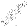
- FIG. 1 shows a section of a trailing antenna.
- a single converter 10 20, 30, ... 4n at an angle ⁇ 1, ⁇ 2, ..., ⁇ n , to a reference axis 200.
- the angles ⁇ n are arbitrary, their selection is stochastic.
- the reference axis 200 is perpendicular to the longitudinal axis 300 of the trailing antenna.
- Each sensor 400 contains two static accelerometers aligned in the x and y directions.
- Each transducer which can be arranged at one of the six angles ⁇ 1, ..., ⁇ 6, has a transverse distance q1, q2, ..., q6 to the reference axis 200. From the transverse distances q1, ..., q6 run times ⁇ 1, ..., ⁇ 6 a sound wave based on the longitudinal axis 300 are calculated, which are dependent on the angle ⁇ 1, ..., ⁇ 6, the radius r and the speed of sound c. In addition, the transit time ⁇ 1, ..., ⁇ 6 depends on the angle of incidence ⁇ of the sound wave to a transverse axis 500.
- the main receiving direction of a directional characteristic formed from the received signals of the transducers is pivoted in this direction. If the trailing antenna is twisted, the angle of inclination ⁇ must be added to the angle ⁇ in order to calculate the enlargement time ⁇ for the received signals.
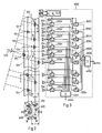
- the direction generator 1000 and a trailing antenna which has a statistical converter distribution from six different possible installation locations according to FIG. 2 on an outer cylinder jacket with a longitudinal axis 300 and a radius r, is shown in FIG. 3.
- Sound waves are incident at the angle of incidence ⁇ to the left of the longitudinal direction 300 and are evaluated with the directional characteristic which is formed from the received signals of the transducers in the direction generator 1000 and points in the main reception direction ⁇ .
- the same transit times with negative signs are set as delay times - ⁇ n in delay stages 3001, 3002, ..., 30n.
- the delay stages 2001, ..., 200n are followed by a summation circuit 3001, in which a directional characteristic pointing to the left is formed.
- a summation stage 4002 a directional characteristic pointing to the right is formed, which has the same angle of incidence ⁇ to the transverse axis 500.
- the received signals are phase-related due to the delay and add up to a group signal at the output of summation stage 4001, which is significantly larger than the group signal, the directional characteristic of which points to the other side of the trailing antenna and that is present at the output of the other summation stage 4002.
Landscapes
- Physics & Mathematics (AREA)
- Engineering & Computer Science (AREA)
- Acoustics & Sound (AREA)
- Signal Processing (AREA)
- Otolaryngology (AREA)
- Health & Medical Sciences (AREA)
- Remote Sensing (AREA)
- General Physics & Mathematics (AREA)
- Life Sciences & Earth Sciences (AREA)
- General Life Sciences & Earth Sciences (AREA)
- Geophysics (AREA)
- Geology (AREA)
- Environmental & Geological Engineering (AREA)
- Radar, Positioning & Navigation (AREA)
- Measurement Of Velocity Or Position Using Acoustic Or Ultrasonic Waves (AREA)
Abstract
Description
Die Erfindung betrifft eine Schleppantenne mit elektroakustischen Wandlern der im Oberbegriff des Anspruchs 1 genannten Art.The invention relates to a trailing antenna with electroacoustic transducers of the type mentioned in the preamble of claim 1.
In der Wasserschalltechnik werden Peilanlagen mit vom Wasserfahrzeug nachgeschleppten Schleppantennen großer Länge eingesetzt, um über große Entfernungen Ziele zu detektieren und zu peilen. Die Ausbreitung von Schallwellen ist frequenzabhängig. Zum Erzielen großer Reichweiten wird wegen der geringeren Dämpfung der Schallwellen im tieffrequenten Bereich gepeilt. Die Peilgenauigeit ist abhängig vom Öffnungswinkel der Richtcharakteristik einer Antenne. Der Öffnungswinkel ist um so größer, je niedriger die Frequenz der empfangenen Schallwellen ist, und um so kleiner, je länger die Antenne ist. Mit Schleppantennen lassen sich Öffnungswinkel realisieren, die auch über große Entfernungen eine Peilung zum Ziel in ausreichender Auflösung gestatten. Mit einem Richtungsbildner werden Empfangssignale von rundum druckempfindlichen, elektroakustischen Wandlern, die in der Schleppantenne angeordnet sind, zu Richtcharakteristiksignalen zusammengefaßt, deren Richtcharakteristiken seitlich zur Schleppantenne in unterschiedliche Richtungen weisen. Die Form der Richtcharakteristiken gestattet jedoch keine Unterscheidung, ob ein aufgefaßtes Ziel rechts oder links von der Schleppantenne liegt.Direction finding systems are used in waterborne sound technology with long antennas towed by the watercraft in order to detect and aim at long-range targets. The propagation of sound waves is frequency-dependent. In order to achieve long ranges, the low-frequency range is used because of the lower damping of the sound waves. The directional accuracy depends on the aperture angle of the directional characteristic of an antenna. The opening angle is larger, the lower the frequency of the received sound waves, and the smaller, the longer the antenna. Trailing antennas can be used to achieve opening angles that allow a bearing to the target in sufficient resolution even over long distances. With a directional generator, received signals from all-round pressure-sensitive, electroacoustic transducers, which are arranged in the trailing antenna, are combined to form directional characteristic signals, the directional characteristics of which point laterally to the trailing antenna in different directions. However, the shape of the directional characteristics does not allow a distinction to be made as to whether a perceived target lies to the right or left of the trailing antenna.
Eine Seitenkennung ist beispielsweise mit Wandlern in der Schleppantenne möglich, die in einer Vorzugsrichtung empfindlich und nicht rundum empfindlich sind. In der DE-OS 3 151 028 werden je Wandlerort drei Wandler im Dreieck mit Querabstand zur Längsrichtung angeordnet und paarweise zu je einem Kardioidensignal zusammengefaßt, das jeweils zu einer Seite seine höchste Empfangsempfindlichkeit und zur anderen Seite eine Nullstelle aufweist. Der Aufwand mit mehreren Wandlern an einem Wandlerort, die einen Querabstand zur Längsrichtung aufweisen, ist erheblich. Die Schleppantenne wird in ihrem Aufbau wesentlich aufwendiger, komplizierter, störanfälliger und schwerer.A side identifier is possible, for example, with transducers in the trailing antenna that are in a preferred direction are sensitive and not completely sensitive. In DE-OS 3 151 028, three transducers are arranged in a triangle at a transverse distance from the longitudinal direction for each transducer location and are combined in pairs to form a cardioid signal, each of which has its highest reception sensitivity and a zero on the other side. The effort with several transducers at one transducer location, which are at a transverse distance to the longitudinal direction, is considerable. The structure of the trailing antenna is much more complex, complicated, prone to interference and heavier.
Es ist Aufgabe der vorliegenden Erfindung, eine Schleppantenne der im Oberbegriff des Anspruchs 1 genannten Art zu schaffen, mit der eine eindeutige Peilung möglich ist, ohne daß die Zahl der benötigten Wandler steigt.It is an object of the present invention to provide a trailing antenna of the type mentioned in the preamble of claim 1, with which a clear bearing is possible without the number of converters required increasing.
Diese Aufgabe wird erfindungsgemäß durch die im Kennzeichenteil des Anspruchs 1 genannten Merkmale gelöst.This object is achieved by the features mentioned in the characterizing part of claim 1.
Durch den Querabstand, den der Wandler an jedem Wandlerort zur Längsachse aufweist, werden Empfangssignale zum Bilden einer Richtcharakteristik, die zu einer Seite der Schleppantenne ihre Hauptempfangsrichtung aufweist, mit positiven Laufzeiten und für eine Richtcharakteristik zur anderen Seite mit negativen Laufzeiten beaufschlagt, wie es in der DE-OS 39 10 906 für Empfangssignale von Wandlern einer Schleppantenne beschrieben ist, die nicht langgestreckt, sondern durch Fahrzeugmanöver örtlich von der Fahrtrichtung eines schleppenden Wasserfahrzeugs abweicht, so daß die Wandler einen Querabstand zur Fahrtrichtung und somit Längsrichtung aufweisen. Der Vorteil der erfindungsgemäßen Schleppantenne nach Anspruch 1 besteht darin, daß auch bei einer schnurgeraden Lage der Schleppantenne eine Seitenkennung gesichert ist, so daß ohne Zeitverzug ständig eine eindeutige Peilung gewährleistet ist. Diese Präsenz ist besonders dann von großem Vorteil, wenn kurzfristig gewarnt und reagiert werden muß, z. B. vor einem Torpedoangriff. Der Einsatz der erfindungsgemäßen Schleppantenne bei aktiver Ortung ist besonders vorteilhaft, da auch während der kurzen Dauer eines einzigen, von einem Ziel reflektierten Empfangsimpulses stets eine eindeutige Peilung zum Ziel mit der Schleppantenne möglich ist. Diese Forderung zu erfüllen, ist besonders wichtig, da Zeitabstände zwischen Sendeimpulsen wegen der großen Reichweiten groß sind und Empfangszeiten wegen der kurzen Pulslängen sehr kurz sind.The transverse distance that the transducer has at each transducer location from the longitudinal axis means that reception signals for forming a directional characteristic, which has its main reception direction on one side of the trailing antenna, are subjected to positive transit times and negative propagation times for a directional characteristic to the other side, as in the DE-OS 39 10 906 for reception signals from transducers of a towing antenna is described, which is not elongated, but locally deviates from the direction of travel of a towing watercraft by vehicle maneuvers, so that the transducers have a transverse distance to the direction of travel and thus longitudinal direction. The advantage of the trailing antenna according to the invention is that even with a straight line Position of the trailing antenna a side identifier is secured, so that a clear bearing is guaranteed without delay. This presence is particularly advantageous when there is a need to warn and react at short notice, e.g. B. before a torpedo attack. The use of the trailing antenna according to the invention with active localization is particularly advantageous since, even during the short duration of a single reception pulse reflected by a target, a clear bearing to the target is always possible with the trailing antenna. It is particularly important to meet this requirement, since time intervals between transmission pulses are long because of the large ranges and reception times are very short because of the short pulse lengths.
Der besondere Vorteil der erfindungsgemäßen Schleppantenne gegenüber solchen Verfahren, bei denen ein Kardioidensignal wie beispielsweise in der DE OS 31 51 028 gebildet wird und damit die Richtcharakteristik geformt wird, besteht darin, daß pro Wandlerort ein einziger Wandler und nicht mindestens ein Wandlerpaar vorgesehen werden muß, so daß der Aufwand der gleiche ist, wie bei einer Anordnung gemäß der DE-OS 39 10 906.The particular advantage of the trailing antenna according to the invention over such methods in which a cardioid signal is formed, for example in DE OS 31 51 028, and thus the directional characteristic is formed, is that a single transducer and not at least one pair of transducers must be provided per transducer location, so that the effort is the same as with an arrangement according to DE-OS 39 10 906.
Die Wandler liegen auf einem Zylinderaußenmantel, dessen Höhe die Längsachse der Schleppantenne ist. Zwischen einer Bezugsachse senkrecht zur Längsachse und dem Querabstand des Wandlers liegt an jedem Wandlerort ein anderer Winkel, so daß die Wandler, wenn sie von Wandlerort zu Wandlerort um das gleiche Winkelinkrement versetzt angeordnet sind, sich auf einer Spirale längs des Zylinderaußenmantels befinden. Um auch bei großen Schwenkwinkeln der Hauptempfangsrichtung der Richtcharakteristik keine Fehlpeilungen aufgrund von sog. Grating-Lobes zu erhalten, muß der Abstand der Wandlerorte deutlich kleiner als die halbe Wellenlänge der höchsten zu empfangenden Frequenz sein. Mit einer solchen Anordnung der Wandler ist auch eine Kardioidenbildung möglich. Es werden dann Empfangssignale von Wandlern an zwei oder drei benachbarten Wandlerorten durch Summen- und Differenzbildung und/oder Verzögerungen zu Kardioidensignalen zusammengefaßt und mit diesen Kardioidensignalen eine schwenkbare Richtcharakteristik geformt, deren Hauptempfangsrichtung ebenfalls eindeutig zu einer Seite der Schleppantenne weist, wie es beispielsweise in der deutschen Offenlegungsschrift 31 51 028 beschrieben ist.The transducers lie on an outer cylinder jacket, the height of which is the longitudinal axis of the trailing antenna. At each transducer location there is a different angle between a reference axis perpendicular to the longitudinal axis and the transverse distance of the transducer, so that the transducers, if they are offset by the same angular increment from transducer location to transducer location, are located on a spiral along the outer cylinder jacket. The distance between the transducer locations must be significantly smaller than that in order to avoid incorrect bearing finding due to so-called grating praise, even with large swivel angles of the main direction of reception of the directional characteristic half the wavelength of the highest frequency to be received. Cardioid formation is also possible with such an arrangement of the transducers. Received signals from transducers at two or three adjacent transducer locations are then combined into sum and difference formation and / or delays to form cardioid signals, and a pivotable directional characteristic is formed with these cardioid signals, the main reception direction of which also clearly points to one side of the trailing antenna, as is the case, for example, in the German one Laid-open specification 31 51 028.
Eine Zusammenfassung der Empfangssignale dreier Wandler an drei Wandlerorten zu einer Achtercharakteristik und einer Rundumcharakteristik und einer anschließenden Richtungsbildung, wie es in der US-PS 41 79 682 beschrieben ist, ist ebenfalls mit der Schleppantenne nach Anspruch 1 möglich, da benachbarte Wandler jeweils einen Querabstand zur Längsrichtung und in Längsrichtung der Schleppantenne Abstände kleiner als die halbe Wellenlänge der höchsten empfangenen Frequenz aufweisen.A summary of the received signals of three transducers at three transducer locations to form an eight-way characteristic and an all-round characteristic and a subsequent directional formation, as described in US Pat. No. 4,179,682, is also possible with the trailing antenna according to claim 1, since adjacent transducers each have a transverse distance In the longitudinal direction and in the longitudinal direction of the trailing antenna, the distances are smaller than half the wavelength of the highest received frequency.
Der Vorteil der Schleppantenne nach Anspruch 1 besteht darin, daß sowohl eine Richtungsbildung mit den Empfangssignalen der einzelnen Wandler durch Verzögerung und Addition, wie auch nach Bilden von Kardioidensignalen oder Achtercharakteristiksignalen möglich ist, wobei jeweils jeder Wandlerort nur einen einzigen Wandler aufweist.The advantage of the trailing antenna according to claim 1 is that it is possible to form a direction with the received signals of the individual transducers by delay and addition, as well as after forming cardioid signals or figure eight characteristic signals, each transducer location having only a single transducer.
Gemäß der vorteilhaften Weiterbildung nach Anspruch 2 werden die Winkel für die Wandlerorte zwischen 0° und 360° statistisch ausgewählt. Der Vorteil besteht darin, daß mit der Laufzeitkompensation auf eine Bezugsebene senkrecht zur Horizontalen eine statistische Verteilung der Wandler in Längsrichtung erreicht wird und somit auch bei Abständen der Wandlerorte größer als der halben Wellenlänge der empfangenen Schallwellen eine eindeutige Peilung ohne sog. Grating-Lobes gewährleistet ist, wie es beispielsweise in der US-PS 3 811 129 für eine ebene, flächige Wandleranordnung angegeben ist. Ein weiterer Vorteil besteht darin, daß durch die statistische Auswahl der Winkel Periodizitäten des Antennenaufbaus in Längsrichtung vermieden werden, die durch eine spiralförmige Wandleranordnung entstünden. Diese würden auch zu Grating-Lobes führen.According to the advantageous development according to claim 2, the angles for the converter locations between 0 ° and 360 ° are selected statistically. The advantage is that with the runtime compensation on a reference plane perpendicular to Horizontal a statistical distribution of the transducers in the longitudinal direction is achieved and thus a clear bearing without so-called grating praise is guaranteed even at distances between the transducer locations greater than half the wavelength of the received sound waves, as is the case, for example, in US Pat. No. 3,811,129 for a flat, flat transducer arrangement is specified. Another advantage is that the statistical selection of the angles avoids periodicities of the antenna structure in the longitudinal direction, which would result from a spiral converter arrangement. This would also lead to grating praise.
Die gleichen Vorteile werden bei einer Anordnung der Wandler nach der Weiterbildung der erfindungsgemäßen Schleppantenne nach Anspruch 3 erzielt, die sich zusätzlich durch eine Vereinfachung der Wandleraufhängung in der Schleppantenne auszeichnet. Gibt man beispielsweise sechs Winkelpositionen mit einem Winkelabstand von 30° vor, so benötigt man nur drei verschiedene Formstücke für die Unterbringung der Wandler in der Schleppantenne, da jeweils drei Winkelpositionen symmetrisch zur Horizontalen angeordnet sind, wenn zwei Zugseile der Schleppantenne durch die Formstücke in der Horizontalen geführt sind. Solche Formstücke sind beispielsweise aus schalldurchlässigem Kunststoff, in denen die Wandler in Schaumstoff gelagert sind.The same advantages are achieved with an arrangement of the transducers according to the development of the trailing antenna according to claim 3, which is additionally characterized by a simplification of the transducer suspension in the trailing antenna. For example, if you specify six angular positions with an angular spacing of 30 °, you only need three different fittings to accommodate the transducers in the trailing antenna, since three angular positions are arranged symmetrically to the horizontal when two traction cables of the trailing antenna through the fittings in the horizontal are led. Such fittings are made of sound-permeable plastic, for example, in which the transducers are mounted in foam.
Da eine Torsion der Schleppantenne in ihrer Längsachse nicht auszuschließen ist, wird gemäß Anspruch 4 - zumindest in dem Teil der Schleppantenne, der für eine Seitenkennung verwendet wird - am Anfang und Ende ein Sensor zum Bestimmen der Verdrehung vorgesehen. Wenn alle Wandler der Schleppantenne an der Seitenkennung beteiligt sind, müssen entsprechend mehrere Sensoren vorgesehen werden.Since torsion of the trailing antenna in its longitudinal axis cannot be ruled out, a sensor for determining the rotation is provided at the beginning and end, at least in the part of the trailing antenna that is used for a side identifier. If all transducers of the trailing antenna are involved in the side identification, accordingly, several sensors are provided.
Nach der vorteilhaften Weiterbildung der erfindungsgemäßen Schleppantenne nach Anspruch 5 und 6 werden statische Beschleunigungsaufnehmer oder Pendel eingesetzt, deren Lagesignale zusammen mit den Empfangssignalen an den Richtungsbildner übertragen werden. Der Vorteil einer Verwendung von rechtwinklig angeordneten, statischen Beschleunigungsaufnehmern zur Bestimmung der Verdrehung der Schleppantenne besteht darin, daß sie ohne spezielle Anpassung, sondern so, wie sie am Markt erhältlich sind, mittig in die Schleppantenne eingebaut werden können.According to the advantageous further development of the trailing antenna according to the invention according to
Die Erfindung ist anhand eines Ausführungsbeispiels für eine Schleppantenne mit elektroakustischen Wandlern, die in einem Querabstand zur Längsachse der Schleppantenne angeordnet sind, näher erläutert. Es zeigen:
- Fig. 1
- einen Abschnitt der Schleppantenne,
- Fig.2
- einen Querschnitt mit möglichen Einbauwinkelorten und
- Fig. 3
- eine Wandlerverteilung längs der Schleppantenne mit Richtungsbildner.
- Fig. 1
- a section of the tow antenna,
- Fig. 2
- a cross section with possible installation angle locations and
- Fig. 3
- a transducer distribution along the trailing antenna with directional.
In Fig. 1 ist ein Abschnitt einer Schleppantenne dargestellt. An jedem Wandlerort 101, 102, ..., 10n befindet sich ein einziger Wandler 10, 20, 30, ... 4n unter einem Winkel φ₁, φ₂, ..., φn, zu einer Bezugsachse 200. Die Winkel φn, sind beliebig, ihre Auswahl erfolgt stochastisch. Die Bezugsachse 200 steht senkrecht zur Längsachse 300 der Schleppantenne. Auf der Längsachse 300 befinden sich zwei Sensoren 400, mit denen Neigungswinkel θa und θe oder Torsionswinkel um die Längsachse 300 gemessen werden. Jeder Sensor 400 enthält zwei in x- und y-Richtung ausgerichtete statische Beschleunigungsaufnehmer.1 shows a section of a trailing antenna. At each
Fig. 2 zeigt einen Querschnitt der Schleppantenne mit sechs verschiedenen Winkelpositionen I, II, III, ..., VI unter den Winkel φ₁, φ₂, ..., φ₆ für Wandler. Aus dieser beschränkten Anzahl von sechs Winkeln φ₁ = 30°, φ₂ = 90°, ..., φ₆ = 330° werden stochastisch die Winkelpositionen I, II, ..., VI für jeden Wandlerort 101, 102, ..., 10n ausgewählt. In den Querschnitt mit dem Radius r sind Durchführungen 600 für Zugseile angegeben. Die Winkelpositionen I, II, ..., VI liegen zu einer Verbindungslinie zwischen den Durchführungen 600 symmetrisch. Jeder Wandler, der unter einem der sechs Winkel φ₁, ..., φ₆ angeordnet werden kann, weist einen Querabstand q₁, q₂, ..., q₆ zur Bezugsachse 200 auf. Aus den Querabständen q₁, ..., q₆ werden Laufzeiten τ₁, ..., τ₆ einer Schallwelle bezogen auf die Längsachse 300 berechnet, die abhängig sind vom Winkel φ₁, ..., φ₆, dem Radius r und der Schallgeschwindigkeit c. Außerdem ist die Laufzeit τ₁, ..., τ₆ abhängig vom Einfallswinkel β der Schallwelle zu einer Querachse 500. Zum Bestimmen des Einfallswinkels β wird die Hauptempfangsrichtung einer aus den Empfangssignalen der Wandler gebildeten Richtcharakteristik in diese Richtung geschwenkt. Bei einer Torsion der Schleppantenne ist zum Berechnen der Vergrößerungszeit τ für die Empfangssignale zu dem Winkel φ der Neigungswinkel θ hinzuzuaddieren.Fig. 2 shows a cross section of the trailing antenna with six different angular positions I, II, III, ..., VI at the angles φ₁, φ₂, ..., φ₆ for transducers. From this limited number of six angles φ₁ = 30 °, φ₂ = 90 °, ..., φ₆ = 330 °, the angular positions I, II, ..., VI are stochastically for each
Für den Einfallswinkel β, in den die Hauptempfangsrichtung der Richtcharakteristik weist, werden die Laufzeiten der Schallwelle durch Verzögerungszeiten![]()

![]()
In dem Fall, in dem die Hauptempfangsrichtung der Richtcharakteristik in Richtung zum Schallwellen abstrahlenden oder reflektierenden Ziel weist, sind die Empfangssignale durch die Verzögerung konphas und addieren sich zu einem Gruppensignal am Ausgang der Summationsstufe 4001, das wesentlich größer ist als das Gruppensignal, dessen Richtcharakteristik zur anderen Seite der Schleppantenne weist und das am Ausgang der anderen Summationsstufe 4002 ansteht.In the case in which the main direction of reception of the directional characteristic points in the direction of the sound wave radiating or reflecting target, the received signals are phase-related due to the delay and add up to a group signal at the output of
Claims (6)
Applications Claiming Priority (2)
| Application Number | Priority Date | Filing Date | Title |
|---|---|---|---|
| DE19944445549 DE4445549C1 (en) | 1994-12-20 | 1994-12-20 | Trailing antenna for long range marine target direction detection |
| DE4445549 | 1994-12-20 |
Publications (2)
| Publication Number | Publication Date |
|---|---|
| EP0718640A2 true EP0718640A2 (en) | 1996-06-26 |
| EP0718640A3 EP0718640A3 (en) | 1998-01-07 |
Family
ID=6536434
Family Applications (1)
| Application Number | Title | Priority Date | Filing Date |
|---|---|---|---|
| EP95119614A Withdrawn EP0718640A3 (en) | 1994-12-20 | 1995-12-13 | Towed array |
Country Status (2)
| Country | Link |
|---|---|
| EP (1) | EP0718640A3 (en) |
| DE (1) | DE4445549C1 (en) |
Families Citing this family (4)
| Publication number | Priority date | Publication date | Assignee | Title |
|---|---|---|---|---|
| USD436348S1 (en) | 1998-07-03 | 2001-01-16 | Gn Netcom A/S | Headset |
| US6526147B1 (en) * | 1998-11-12 | 2003-02-25 | Gn Netcom A/S | Microphone array with high directivity |
| USD452493S1 (en) | 2000-01-05 | 2001-12-25 | Gn Netcom, Inc. | Microphone array |
| DE102011121007B4 (en) * | 2011-12-13 | 2013-08-29 | Atlas Elektronik Gmbh | Device and method for displaying determined target parameters in a reconnaissance area lying targets with a display |
Citations (4)
| Publication number | Priority date | Publication date | Assignee | Title |
|---|---|---|---|---|
| US3811129A (en) | 1972-10-24 | 1974-05-14 | Martin Marietta Corp | Antenna array for grating lobe and sidelobe suppression |
| US4179682A (en) | 1978-08-03 | 1979-12-18 | Sanders Associates, Inc. | Tilt compensation for acoustic transducing system |
| DE3151028A1 (en) | 1981-12-23 | 1983-07-28 | Fried. Krupp Gmbh, 4300 Essen | Acoustical underwater antenna |
| DE3910906A1 (en) | 1989-04-05 | 1990-10-11 | Krupp Atlas Elektronik Gmbh | Method for direction forming in the case of a towed acoustic underwater antenna |
Family Cites Families (4)
| Publication number | Priority date | Publication date | Assignee | Title |
|---|---|---|---|---|
| CA1136255A (en) * | 1978-08-17 | 1982-11-23 | Huntec (70) Limited | Body motion compensation filter with pitch and roll correction |
| DE3248459A1 (en) * | 1982-12-29 | 1989-11-09 | Krupp Atlas Elektronik Gmbh | Acoustic underwater antenna |
| GB2212693B (en) * | 1987-11-18 | 1991-08-14 | Plessey Co Plc | Transducer array |
| FR2651950B1 (en) * | 1989-09-08 | 1992-04-17 | Thomson Csf | LINEAR HYDROPHONIC ANTENNA AND ELECTRONIC RIGHT-LEFT AMBIGUITY LIFTING DEVICE ASSOCIATED WITH THIS ANTENNA. |
-
1994
- 1994-12-20 DE DE19944445549 patent/DE4445549C1/en not_active Expired - Fee Related
-
1995
- 1995-12-13 EP EP95119614A patent/EP0718640A3/en not_active Withdrawn
Patent Citations (4)
| Publication number | Priority date | Publication date | Assignee | Title |
|---|---|---|---|---|
| US3811129A (en) | 1972-10-24 | 1974-05-14 | Martin Marietta Corp | Antenna array for grating lobe and sidelobe suppression |
| US4179682A (en) | 1978-08-03 | 1979-12-18 | Sanders Associates, Inc. | Tilt compensation for acoustic transducing system |
| DE3151028A1 (en) | 1981-12-23 | 1983-07-28 | Fried. Krupp Gmbh, 4300 Essen | Acoustical underwater antenna |
| DE3910906A1 (en) | 1989-04-05 | 1990-10-11 | Krupp Atlas Elektronik Gmbh | Method for direction forming in the case of a towed acoustic underwater antenna |
Also Published As
| Publication number | Publication date |
|---|---|
| EP0718640A3 (en) | 1998-01-07 |
| DE4445549C1 (en) | 1996-03-07 |
Similar Documents
| Publication | Publication Date | Title |
|---|---|---|
| DE2854783C2 (en) | ||
| DE4344509B4 (en) | Method for measuring the acoustic backscattering property of water bodies | |
| DE102009042968A1 (en) | Method and device for measuring a soil profile | |
| DE2709296A1 (en) | ACOUSTIC DEPTH MEASURING DEVICE | |
| DE3221013A1 (en) | METHOD FOR UNDERWATER LOCATION WITH SOUND IMPULSES, IN PARTICULAR FOR DETECTION AND / OR CLASSIFICATION ON OR CLOSE TO THE BASE OF WATER, AND DEVICE FOR IMPLEMENTING THE METHOD | |
| EP2145203B1 (en) | Method for locating a sound-projecting target | |
| DE2118300C3 (en) | Method for determining the position of a watercraft and device for its implementation | |
| EP1393025A2 (en) | Method for determining the mean speed of sound in a body of water | |
| DE3151028C2 (en) | ||
| DE4445549C1 (en) | Trailing antenna for long range marine target direction detection | |
| DE19612503C2 (en) | Electroacoustic transducer module | |
| DE2931818C2 (en) | Device for detecting the direction of incidence of electromagnetic, in particular optical, radiation | |
| EP0253277B1 (en) | Passive method for estimating data of a target moving in water and radiating time continuous sound signals | |
| EP2480910A1 (en) | Method and device for measuring a profile of the ground | |
| DE19516727C1 (en) | Underwater sound transmitter for bistatic towed sonar location array | |
| EP1001275B1 (en) | Apparatus for determining the angle of incidence of incoming time limited sound waves | |
| EP0660130B1 (en) | Method for measuring the direction of arrival of pulsed sound waves emitted form targets | |
| EP0450191B1 (en) | Transducer arrangement | |
| DE4341364C2 (en) | Method for side identification for a direction finder with trailing antenna | |
| DE3334008C2 (en) | ||
| DE19825271C1 (en) | Procedure for the passive determination of target data | |
| EP1500953A1 (en) | Method for determining target data using an active sonar | |
| EP0821343B1 (en) | Method for forming signal groups | |
| DE19701041C2 (en) | Method and device for measuring a directional diagram | |
| DE3314220C2 (en) |
Legal Events
| Date | Code | Title | Description |
|---|---|---|---|
| PUAI | Public reference made under article 153(3) epc to a published international application that has entered the european phase |
Free format text: ORIGINAL CODE: 0009012 |
|
| AK | Designated contracting states |
Kind code of ref document: A2 Designated state(s): FR GB IT SE |
|
| PUAL | Search report despatched |
Free format text: ORIGINAL CODE: 0009013 |
|
| AK | Designated contracting states |
Kind code of ref document: A3 Designated state(s): FR GB IT SE |
|
| 17P | Request for examination filed |
Effective date: 19971219 |
|
| 17Q | First examination report despatched |
Effective date: 19990705 |
|
| STAA | Information on the status of an ep patent application or granted ep patent |
Free format text: STATUS: THE APPLICATION HAS BEEN WITHDRAWN |
|
| 18W | Application withdrawn |
Withdrawal date: 19991028 |