EP0718640A2 - Antenne remorquée - Google Patents
Antenne remorquée Download PDFInfo
- Publication number
- EP0718640A2 EP0718640A2 EP95119614A EP95119614A EP0718640A2 EP 0718640 A2 EP0718640 A2 EP 0718640A2 EP 95119614 A EP95119614 A EP 95119614A EP 95119614 A EP95119614 A EP 95119614A EP 0718640 A2 EP0718640 A2 EP 0718640A2
- Authority
- EP
- European Patent Office
- Prior art keywords
- transducer
- angle
- transducers
- trailing antenna
- antenna
- Prior art date
- Legal status (The legal status is an assumption and is not a legal conclusion. Google has not performed a legal analysis and makes no representation as to the accuracy of the status listed.)
- Withdrawn
Links
Images
Classifications
-
- G—PHYSICS
- G01—MEASURING; TESTING
- G01V—GEOPHYSICS; GRAVITATIONAL MEASUREMENTS; DETECTING MASSES OR OBJECTS; TAGS
- G01V1/00—Seismology; Seismic or acoustic prospecting or detecting
- G01V1/16—Receiving elements for seismic signals; Arrangements or adaptations of receiving elements
- G01V1/20—Arrangements of receiving elements, e.g. geophone pattern
- G01V1/201—Constructional details of seismic cables, e.g. streamers
-
- G—PHYSICS
- G01—MEASURING; TESTING
- G01S—RADIO DIRECTION-FINDING; RADIO NAVIGATION; DETERMINING DISTANCE OR VELOCITY BY USE OF RADIO WAVES; LOCATING OR PRESENCE-DETECTING BY USE OF THE REFLECTION OR RERADIATION OF RADIO WAVES; ANALOGOUS ARRANGEMENTS USING OTHER WAVES
- G01S3/00—Direction-finders for determining the direction from which infrasonic, sonic, ultrasonic, or electromagnetic waves, or particle emission, not having a directional significance, are being received
- G01S3/80—Direction-finders for determining the direction from which infrasonic, sonic, ultrasonic, or electromagnetic waves, or particle emission, not having a directional significance, are being received using ultrasonic, sonic or infrasonic waves
- G01S3/802—Systems for determining direction or deviation from predetermined direction
- G01S3/808—Systems for determining direction or deviation from predetermined direction using transducers spaced apart and measuring phase or time difference between signals therefrom, i.e. path-difference systems
- G01S3/8083—Systems for determining direction or deviation from predetermined direction using transducers spaced apart and measuring phase or time difference between signals therefrom, i.e. path-difference systems determining direction of source
-
- H—ELECTRICITY
- H04—ELECTRIC COMMUNICATION TECHNIQUE
- H04R—LOUDSPEAKERS, MICROPHONES, GRAMOPHONE PICK-UPS OR LIKE ACOUSTIC ELECTROMECHANICAL TRANSDUCERS; DEAF-AID SETS; PUBLIC ADDRESS SYSTEMS
- H04R1/00—Details of transducers, loudspeakers or microphones
- H04R1/20—Arrangements for obtaining desired frequency or directional characteristics
- H04R1/32—Arrangements for obtaining desired frequency or directional characteristics for obtaining desired directional characteristic only
- H04R1/326—Arrangements for obtaining desired frequency or directional characteristics for obtaining desired directional characteristic only for microphones
-
- H—ELECTRICITY
- H04—ELECTRIC COMMUNICATION TECHNIQUE
- H04R—LOUDSPEAKERS, MICROPHONES, GRAMOPHONE PICK-UPS OR LIKE ACOUSTIC ELECTROMECHANICAL TRANSDUCERS; DEAF-AID SETS; PUBLIC ADDRESS SYSTEMS
- H04R1/00—Details of transducers, loudspeakers or microphones
- H04R1/20—Arrangements for obtaining desired frequency or directional characteristics
- H04R1/32—Arrangements for obtaining desired frequency or directional characteristics for obtaining desired directional characteristic only
- H04R1/40—Arrangements for obtaining desired frequency or directional characteristics for obtaining desired directional characteristic only by combining a number of identical transducers
- H04R1/406—Arrangements for obtaining desired frequency or directional characteristics for obtaining desired directional characteristic only by combining a number of identical transducers microphones
-
- H—ELECTRICITY
- H04—ELECTRIC COMMUNICATION TECHNIQUE
- H04R—LOUDSPEAKERS, MICROPHONES, GRAMOPHONE PICK-UPS OR LIKE ACOUSTIC ELECTROMECHANICAL TRANSDUCERS; DEAF-AID SETS; PUBLIC ADDRESS SYSTEMS
- H04R1/00—Details of transducers, loudspeakers or microphones
- H04R1/44—Special adaptations for subaqueous use, e.g. for hydrophone
Definitions
- the invention relates to a trailing antenna with electroacoustic transducers of the type mentioned in the preamble of claim 1.
- Direction finding systems are used in waterborne sound technology with long antennas towed by the watercraft in order to detect and aim at long-range targets.
- the propagation of sound waves is frequency-dependent.
- the low-frequency range is used because of the lower damping of the sound waves.
- the directional accuracy depends on the aperture angle of the directional characteristic of an antenna. The opening angle is larger, the lower the frequency of the received sound waves, and the smaller, the longer the antenna. Trailing antennas can be used to achieve opening angles that allow a bearing to the target in sufficient resolution even over long distances.
- a directional generator With a directional generator, received signals from all-round pressure-sensitive, electroacoustic transducers, which are arranged in the trailing antenna, are combined to form directional characteristic signals, the directional characteristics of which point laterally to the trailing antenna in different directions.
- the shape of the directional characteristics does not allow a distinction to be made as to whether a perceived target lies to the right or left of the trailing antenna.
- a side identifier is possible, for example, with transducers in the trailing antenna that are in a preferred direction are sensitive and not completely sensitive.
- transducers in the trailing antenna that are in a preferred direction are sensitive and not completely sensitive.
- three transducers are arranged in a triangle at a transverse distance from the longitudinal direction for each transducer location and are combined in pairs to form a cardioid signal, each of which has its highest reception sensitivity and a zero on the other side.
- the effort with several transducers at one transducer location, which are at a transverse distance to the longitudinal direction, is considerable.
- the structure of the trailing antenna is much more complex, complicated, prone to interference and heavier.
- the transverse distance that the transducer has at each transducer location from the longitudinal axis means that reception signals for forming a directional characteristic, which has its main reception direction on one side of the trailing antenna, are subjected to positive transit times and negative propagation times for a directional characteristic to the other side, as in the DE-OS 39 10 906 for reception signals from transducers of a towing antenna is described, which is not elongated, but locally deviates from the direction of travel of a towing watercraft by vehicle maneuvers, so that the transducers have a transverse distance to the direction of travel and thus longitudinal direction.
- the advantage of the trailing antenna according to the invention is that even with a straight line Position of the trailing antenna a side identifier is secured, so that a clear bearing is guaranteed without delay. This presence is particularly advantageous when there is a need to warn and react at short notice, e.g. B. before a torpedo attack.
- the use of the trailing antenna according to the invention with active localization is particularly advantageous since, even during the short duration of a single reception pulse reflected by a target, a clear bearing to the target is always possible with the trailing antenna. It is particularly important to meet this requirement, since time intervals between transmission pulses are long because of the large ranges and reception times are very short because of the short pulse lengths.
- the transducers lie on an outer cylinder jacket, the height of which is the longitudinal axis of the trailing antenna. At each transducer location there is a different angle between a reference axis perpendicular to the longitudinal axis and the transverse distance of the transducer, so that the transducers, if they are offset by the same angular increment from transducer location to transducer location, are located on a spiral along the outer cylinder jacket.
- the distance between the transducer locations must be significantly smaller than that in order to avoid incorrect bearing finding due to so-called grating praise, even with large swivel angles of the main direction of reception of the directional characteristic half the wavelength of the highest frequency to be received. Cardioid formation is also possible with such an arrangement of the transducers.
- Received signals from transducers at two or three adjacent transducer locations are then combined into sum and difference formation and / or delays to form cardioid signals, and a pivotable directional characteristic is formed with these cardioid signals, the main reception direction of which also clearly points to one side of the trailing antenna, as is the case, for example, in the German one Laid-open specification 31 51 028.
- the advantage of the trailing antenna according to claim 1 is that it is possible to form a direction with the received signals of the individual transducers by delay and addition, as well as after forming cardioid signals or figure eight characteristic signals, each transducer location having only a single transducer.
- the angles for the converter locations between 0 ° and 360 ° are selected statistically.
- the advantage is that with the runtime compensation on a reference plane perpendicular to Horizontal a statistical distribution of the transducers in the longitudinal direction is achieved and thus a clear bearing without so-called grating praise is guaranteed even at distances between the transducer locations greater than half the wavelength of the received sound waves, as is the case, for example, in US Pat. No. 3,811,129 for a flat, flat transducer arrangement is specified.
- Another advantage is that the statistical selection of the angles avoids periodicities of the antenna structure in the longitudinal direction, which would result from a spiral converter arrangement. This would also lead to grating praise.
- a sensor for determining the rotation is provided at the beginning and end, at least in the part of the trailing antenna that is used for a side identifier. If all transducers of the trailing antenna are involved in the side identification, accordingly, several sensors are provided.
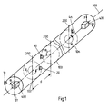
- FIG. 1 shows a section of a trailing antenna.
- a single converter 10 20, 30, ... 4n at an angle ⁇ 1, ⁇ 2, ..., ⁇ n , to a reference axis 200.
- the angles ⁇ n are arbitrary, their selection is stochastic.
- the reference axis 200 is perpendicular to the longitudinal axis 300 of the trailing antenna.
- Each sensor 400 contains two static accelerometers aligned in the x and y directions.
- Each transducer which can be arranged at one of the six angles ⁇ 1, ..., ⁇ 6, has a transverse distance q1, q2, ..., q6 to the reference axis 200. From the transverse distances q1, ..., q6 run times ⁇ 1, ..., ⁇ 6 a sound wave based on the longitudinal axis 300 are calculated, which are dependent on the angle ⁇ 1, ..., ⁇ 6, the radius r and the speed of sound c. In addition, the transit time ⁇ 1, ..., ⁇ 6 depends on the angle of incidence ⁇ of the sound wave to a transverse axis 500.
- the main receiving direction of a directional characteristic formed from the received signals of the transducers is pivoted in this direction. If the trailing antenna is twisted, the angle of inclination ⁇ must be added to the angle ⁇ in order to calculate the enlargement time ⁇ for the received signals.
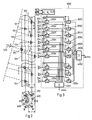
- the direction generator 1000 and a trailing antenna which has a statistical converter distribution from six different possible installation locations according to FIG. 2 on an outer cylinder jacket with a longitudinal axis 300 and a radius r, is shown in FIG. 3.
- Sound waves are incident at the angle of incidence ⁇ to the left of the longitudinal direction 300 and are evaluated with the directional characteristic which is formed from the received signals of the transducers in the direction generator 1000 and points in the main reception direction ⁇ .
- the same transit times with negative signs are set as delay times - ⁇ n in delay stages 3001, 3002, ..., 30n.
- the delay stages 2001, ..., 200n are followed by a summation circuit 3001, in which a directional characteristic pointing to the left is formed.
- a summation stage 4002 a directional characteristic pointing to the right is formed, which has the same angle of incidence ⁇ to the transverse axis 500.
- the received signals are phase-related due to the delay and add up to a group signal at the output of summation stage 4001, which is significantly larger than the group signal, the directional characteristic of which points to the other side of the trailing antenna and that is present at the output of the other summation stage 4002.
Landscapes
- Physics & Mathematics (AREA)
- Engineering & Computer Science (AREA)
- Acoustics & Sound (AREA)
- Health & Medical Sciences (AREA)
- Otolaryngology (AREA)
- Signal Processing (AREA)
- Life Sciences & Earth Sciences (AREA)
- Remote Sensing (AREA)
- General Physics & Mathematics (AREA)
- Environmental & Geological Engineering (AREA)
- Geology (AREA)
- General Life Sciences & Earth Sciences (AREA)
- Geophysics (AREA)
- Radar, Positioning & Navigation (AREA)
- Measurement Of Velocity Or Position Using Acoustic Or Ultrasonic Waves (AREA)
Applications Claiming Priority (2)
| Application Number | Priority Date | Filing Date | Title |
|---|---|---|---|
| DE4445549 | 1994-12-20 | ||
| DE19944445549 DE4445549C1 (de) | 1994-12-20 | 1994-12-20 | Schleppantenne |
Publications (2)
| Publication Number | Publication Date |
|---|---|
| EP0718640A2 true EP0718640A2 (fr) | 1996-06-26 |
| EP0718640A3 EP0718640A3 (fr) | 1998-01-07 |
Family
ID=6536434
Family Applications (1)
| Application Number | Title | Priority Date | Filing Date |
|---|---|---|---|
| EP95119614A Withdrawn EP0718640A3 (fr) | 1994-12-20 | 1995-12-13 | Antenne remorquée |
Country Status (2)
| Country | Link |
|---|---|
| EP (1) | EP0718640A3 (fr) |
| DE (1) | DE4445549C1 (fr) |
Families Citing this family (4)
| Publication number | Priority date | Publication date | Assignee | Title |
|---|---|---|---|---|
| USD436348S1 (en) | 1998-07-03 | 2001-01-16 | Gn Netcom A/S | Headset |
| US6526147B1 (en) * | 1998-11-12 | 2003-02-25 | Gn Netcom A/S | Microphone array with high directivity |
| USD452493S1 (en) | 2000-01-05 | 2001-12-25 | Gn Netcom, Inc. | Microphone array |
| DE102011121007B4 (de) * | 2011-12-13 | 2013-08-29 | Atlas Elektronik Gmbh | Vorrichtung und Verfahren zur Darstellung ermittelter Zielparameter in einem Aufklärungsgebiet liegender Ziele mit einer Anzeige |
Citations (4)
| Publication number | Priority date | Publication date | Assignee | Title |
|---|---|---|---|---|
| US3811129A (en) | 1972-10-24 | 1974-05-14 | Martin Marietta Corp | Antenna array for grating lobe and sidelobe suppression |
| US4179682A (en) | 1978-08-03 | 1979-12-18 | Sanders Associates, Inc. | Tilt compensation for acoustic transducing system |
| DE3151028A1 (de) | 1981-12-23 | 1983-07-28 | Fried. Krupp Gmbh, 4300 Essen | Akustische unterwasserantenne |
| DE3910906A1 (de) | 1989-04-05 | 1990-10-11 | Krupp Atlas Elektronik Gmbh | Verfahren zur richtungsbildung bei einer geschleppten akustischen unterwasserantenne |
Family Cites Families (4)
| Publication number | Priority date | Publication date | Assignee | Title |
|---|---|---|---|---|
| CA1136255A (fr) * | 1978-08-17 | 1982-11-23 | Samuel M. Theodoulou | Filtre de compensation du mouvement d'un corps avec correction du tangage et du roulis |
| DE3248459A1 (de) * | 1982-12-29 | 1989-11-09 | Krupp Atlas Elektronik Gmbh | Akustische unterwasserantenne |
| GB2212693B (en) * | 1987-11-18 | 1991-08-14 | Plessey Co Plc | Transducer array |
| FR2651950B1 (fr) * | 1989-09-08 | 1992-04-17 | Thomson Csf | Antenne hydrophonique lineaire et dispositif electronique de levee d'ambiguite droite-gauche associe a cette antenne. |
-
1994
- 1994-12-20 DE DE19944445549 patent/DE4445549C1/de not_active Expired - Fee Related
-
1995
- 1995-12-13 EP EP95119614A patent/EP0718640A3/fr not_active Withdrawn
Patent Citations (4)
| Publication number | Priority date | Publication date | Assignee | Title |
|---|---|---|---|---|
| US3811129A (en) | 1972-10-24 | 1974-05-14 | Martin Marietta Corp | Antenna array for grating lobe and sidelobe suppression |
| US4179682A (en) | 1978-08-03 | 1979-12-18 | Sanders Associates, Inc. | Tilt compensation for acoustic transducing system |
| DE3151028A1 (de) | 1981-12-23 | 1983-07-28 | Fried. Krupp Gmbh, 4300 Essen | Akustische unterwasserantenne |
| DE3910906A1 (de) | 1989-04-05 | 1990-10-11 | Krupp Atlas Elektronik Gmbh | Verfahren zur richtungsbildung bei einer geschleppten akustischen unterwasserantenne |
Also Published As
| Publication number | Publication date |
|---|---|
| DE4445549C1 (de) | 1996-03-07 |
| EP0718640A3 (fr) | 1998-01-07 |
Similar Documents
| Publication | Publication Date | Title |
|---|---|---|
| DE2854783C2 (fr) | ||
| DE4344509B4 (de) | Verfahren zur Messung der akustischen Rückstreueigenschaft von Gewässerböden | |
| DE102009042968A1 (de) | Verfahren und Vorrichtung zum Vermessen eines Bodenprofils | |
| DE2709296A1 (de) | Akustisches tiefen-messgeraet | |
| DE3221013A1 (de) | Verfahren zur unterwasserortung mit schallimpulsen, insbesondere zur detektion und/oder klassifikation auf oder nahe dem gewaessergrund befindlicher objekte und vorrichtung zur durchfuehrung des verfahrens | |
| EP2145203B1 (fr) | Procédé de relèvement d'une cible à rayonnement acoustique | |
| DE102007034054A1 (de) | Verfahren zum passiven Bestimmen wenigstens der Entfernung zu einem schallabstrahlenden Ziel sowie Sonaranlage | |
| DE2118300C3 (de) | Verfahren zur Bestimmung der Position eines Wasserfahrzeugs und Vorrichtung zu seiner Durchführung | |
| EP1393025A2 (fr) | Methode pour determiner la vitesse du son dans un corps liquide | |
| DE3151028C2 (fr) | ||
| DE4445549C1 (de) | Schleppantenne | |
| DE19612503C2 (de) | Elektroakustischer Wandlermodul | |
| EP0253277B1 (fr) | Procédé passif d'estimation des données d'une cible en mouvement dans l'eau et rayonnement des signaux sonores en temps continu | |
| EP2480910A1 (fr) | Procédé et dispositif de mesure du profil du sol | |
| DE19516727C1 (de) | Unterwasser-Schallsender | |
| EP1001275B1 (fr) | Dispsitif pour déterminer l'angle d'incidence d'ondes acoustiques apparaisants qui sont limitées temporalement | |
| EP0660130B1 (fr) | Méthode pour repérer la direction de cibles qui émettent des ondes acoustiques à impulsions | |
| EP0450191B1 (fr) | Arrangement de transducteurs | |
| DE4341364C2 (de) | Verfahren zur Seitenkennung für eine Peilanlage mit Schleppantenne | |
| DE3334008C2 (fr) | ||
| EP1500953A1 (fr) | Procédé pour la détermination des données cibles utilisant un sonar actif | |
| EP0821343B1 (fr) | Procédé pour former des groupes de signaux | |
| DE19701041C2 (de) | Verfahren und Vorrichtung zur Messung eines Richtdiagramms | |
| DE3314220C2 (fr) | ||
| DE102024106889A1 (de) | Schleppantenne |
Legal Events
| Date | Code | Title | Description |
|---|---|---|---|
| PUAI | Public reference made under article 153(3) epc to a published international application that has entered the european phase |
Free format text: ORIGINAL CODE: 0009012 |
|
| AK | Designated contracting states |
Kind code of ref document: A2 Designated state(s): FR GB IT SE |
|
| PUAL | Search report despatched |
Free format text: ORIGINAL CODE: 0009013 |
|
| AK | Designated contracting states |
Kind code of ref document: A3 Designated state(s): FR GB IT SE |
|
| 17P | Request for examination filed |
Effective date: 19971219 |
|
| 17Q | First examination report despatched |
Effective date: 19990705 |
|
| STAA | Information on the status of an ep patent application or granted ep patent |
Free format text: STATUS: THE APPLICATION HAS BEEN WITHDRAWN |
|
| 18W | Application withdrawn |
Withdrawal date: 19991028 |