EP0718583A1 - Ein/Ausgangskammer für Fluidum und Vorrichtung zur Fluidumströmung - Google Patents
Ein/Ausgangskammer für Fluidum und Vorrichtung zur Fluidumströmung Download PDFInfo
- Publication number
- EP0718583A1 EP0718583A1 EP19950402781 EP95402781A EP0718583A1 EP 0718583 A1 EP0718583 A1 EP 0718583A1 EP 19950402781 EP19950402781 EP 19950402781 EP 95402781 A EP95402781 A EP 95402781A EP 0718583 A1 EP0718583 A1 EP 0718583A1
- Authority
- EP
- European Patent Office
- Prior art keywords
- face
- inlet
- sphere
- ellipsoid
- fluid
- Prior art date
- Legal status (The legal status is an assumption and is not a legal conclusion. Google has not performed a legal analysis and makes no representation as to the accuracy of the status listed.)
- Granted
Links
Images

Classifications
-
- B—PERFORMING OPERATIONS; TRANSPORTING
- B01—PHYSICAL OR CHEMICAL PROCESSES OR APPARATUS IN GENERAL
- B01D—SEPARATION
- B01D1/00—Evaporating
- B01D1/06—Evaporators with vertical tubes
- B01D1/065—Evaporators with vertical tubes by film evaporating
-
- B—PERFORMING OPERATIONS; TRANSPORTING
- B01—PHYSICAL OR CHEMICAL PROCESSES OR APPARATUS IN GENERAL
- B01D—SEPARATION
- B01D3/00—Distillation or related exchange processes in which liquids are contacted with gaseous media, e.g. stripping
- B01D3/14—Fractional distillation or use of a fractionation or rectification column
- B01D3/32—Other features of fractionating columns ; Constructional details of fractionating columns not provided for in groups B01D3/16 - B01D3/30
- B01D3/322—Reboiler specifications
-
- F—MECHANICAL ENGINEERING; LIGHTING; HEATING; WEAPONS; BLASTING
- F25—REFRIGERATION OR COOLING; COMBINED HEATING AND REFRIGERATION SYSTEMS; HEAT PUMP SYSTEMS; MANUFACTURE OR STORAGE OF ICE; LIQUEFACTION SOLIDIFICATION OF GASES
- F25J—LIQUEFACTION, SOLIDIFICATION OR SEPARATION OF GASES OR GASEOUS OR LIQUEFIED GASEOUS MIXTURES BY PRESSURE AND COLD TREATMENT OR BY BRINGING THEM INTO THE SUPERCRITICAL STATE
- F25J3/00—Processes or apparatus for separating the constituents of gaseous or liquefied gaseous mixtures involving the use of liquefaction or solidification
- F25J3/02—Processes or apparatus for separating the constituents of gaseous or liquefied gaseous mixtures involving the use of liquefaction or solidification by rectification, i.e. by continuous interchange of heat and material between a vapour stream and a liquid stream
- F25J3/04—Processes or apparatus for separating the constituents of gaseous or liquefied gaseous mixtures involving the use of liquefaction or solidification by rectification, i.e. by continuous interchange of heat and material between a vapour stream and a liquid stream for air
- F25J3/04406—Processes or apparatus for separating the constituents of gaseous or liquefied gaseous mixtures involving the use of liquefaction or solidification by rectification, i.e. by continuous interchange of heat and material between a vapour stream and a liquid stream for air using a dual pressure main column system
- F25J3/04412—Processes or apparatus for separating the constituents of gaseous or liquefied gaseous mixtures involving the use of liquefaction or solidification by rectification, i.e. by continuous interchange of heat and material between a vapour stream and a liquid stream for air using a dual pressure main column system in a classical double column flowsheet, i.e. with thermal coupling by a main reboiler-condenser in the bottom of low pressure respectively top of high pressure column
-
- F—MECHANICAL ENGINEERING; LIGHTING; HEATING; WEAPONS; BLASTING
- F25—REFRIGERATION OR COOLING; COMBINED HEATING AND REFRIGERATION SYSTEMS; HEAT PUMP SYSTEMS; MANUFACTURE OR STORAGE OF ICE; LIQUEFACTION SOLIDIFICATION OF GASES
- F25J—LIQUEFACTION, SOLIDIFICATION OR SEPARATION OF GASES OR GASEOUS OR LIQUEFIED GASEOUS MIXTURES BY PRESSURE AND COLD TREATMENT OR BY BRINGING THEM INTO THE SUPERCRITICAL STATE
- F25J5/00—Arrangements of cold exchangers or cold accumulators in separation or liquefaction plants
- F25J5/002—Arrangements of cold exchangers or cold accumulators in separation or liquefaction plants for continuously recuperating cold, i.e. in a so-called recuperative heat exchanger
- F25J5/005—Arrangements of cold exchangers or cold accumulators in separation or liquefaction plants for continuously recuperating cold, i.e. in a so-called recuperative heat exchanger in a reboiler-condenser, e.g. within a column
-
- F—MECHANICAL ENGINEERING; LIGHTING; HEATING; WEAPONS; BLASTING
- F28—HEAT EXCHANGE IN GENERAL
- F28D—HEAT-EXCHANGE APPARATUS, NOT PROVIDED FOR IN ANOTHER SUBCLASS, IN WHICH THE HEAT-EXCHANGE MEDIA DO NOT COME INTO DIRECT CONTACT
- F28D9/00—Heat-exchange apparatus having stationary plate-like or laminated conduit assemblies for both heat-exchange media, the media being in contact with different sides of a conduit wall
-
- F—MECHANICAL ENGINEERING; LIGHTING; HEATING; WEAPONS; BLASTING
- F28—HEAT EXCHANGE IN GENERAL
- F28F—DETAILS OF HEAT-EXCHANGE AND HEAT-TRANSFER APPARATUS, OF GENERAL APPLICATION
- F28F9/00—Casings; Header boxes; Auxiliary supports for elements; Auxiliary members within casings
- F28F9/02—Header boxes; End plates
-
- F—MECHANICAL ENGINEERING; LIGHTING; HEATING; WEAPONS; BLASTING
- F25—REFRIGERATION OR COOLING; COMBINED HEATING AND REFRIGERATION SYSTEMS; HEAT PUMP SYSTEMS; MANUFACTURE OR STORAGE OF ICE; LIQUEFACTION SOLIDIFICATION OF GASES
- F25J—LIQUEFACTION, SOLIDIFICATION OR SEPARATION OF GASES OR GASEOUS OR LIQUEFIED GASEOUS MIXTURES BY PRESSURE AND COLD TREATMENT OR BY BRINGING THEM INTO THE SUPERCRITICAL STATE
- F25J2250/00—Details related to the use of reboiler-condensers
- F25J2250/02—Bath type boiler-condenser using thermo-siphon effect, e.g. with natural or forced circulation or pool boiling, i.e. core-in-kettle heat exchanger
-
- F—MECHANICAL ENGINEERING; LIGHTING; HEATING; WEAPONS; BLASTING
- F25—REFRIGERATION OR COOLING; COMBINED HEATING AND REFRIGERATION SYSTEMS; HEAT PUMP SYSTEMS; MANUFACTURE OR STORAGE OF ICE; LIQUEFACTION SOLIDIFICATION OF GASES
- F25J—LIQUEFACTION, SOLIDIFICATION OR SEPARATION OF GASES OR GASEOUS OR LIQUEFIED GASEOUS MIXTURES BY PRESSURE AND COLD TREATMENT OR BY BRINGING THEM INTO THE SUPERCRITICAL STATE
- F25J2290/00—Other details not covered by groups F25J2200/00 - F25J2280/00
- F25J2290/32—Details on header or distribution passages of heat exchangers, e.g. of reboiler-condenser or plate heat exchangers
-
- Y—GENERAL TAGGING OF NEW TECHNOLOGICAL DEVELOPMENTS; GENERAL TAGGING OF CROSS-SECTIONAL TECHNOLOGIES SPANNING OVER SEVERAL SECTIONS OF THE IPC; TECHNICAL SUBJECTS COVERED BY FORMER USPC CROSS-REFERENCE ART COLLECTIONS [XRACs] AND DIGESTS
- Y10—TECHNICAL SUBJECTS COVERED BY FORMER USPC
- Y10S—TECHNICAL SUBJECTS COVERED BY FORMER USPC CROSS-REFERENCE ART COLLECTIONS [XRACs] AND DIGESTS
- Y10S165/00—Heat exchange
- Y10S165/183—Indirect-contact evaporator
-
- Y—GENERAL TAGGING OF NEW TECHNOLOGICAL DEVELOPMENTS; GENERAL TAGGING OF CROSS-SECTIONAL TECHNOLOGIES SPANNING OVER SEVERAL SECTIONS OF THE IPC; TECHNICAL SUBJECTS COVERED BY FORMER USPC CROSS-REFERENCE ART COLLECTIONS [XRACs] AND DIGESTS
- Y10—TECHNICAL SUBJECTS COVERED BY FORMER USPC
- Y10T—TECHNICAL SUBJECTS COVERED BY FORMER US CLASSIFICATION
- Y10T137/00—Fluid handling
- Y10T137/8593—Systems
- Y10T137/85938—Non-valved flow dividers
Definitions
- the present invention relates to a fluid inlet / outlet chamber for a body part of an apparatus in which this fluid circulates, this body part comprising an inlet or outlet face for said fluid, the chamber being intended to be connected to a tight seal on this face.
- the invention applies in particular to heat exchangers, of the thermosiphon type or of the dripping film type, treating in particular at least one two-phase fluid, such as vaporizers-condensers of air distillation installations, evaporators of refrigeration units. , the reboilers of the columns to be distilled, or even to certain heat exchangers arranged in reduced spaces, such as the inter-stage exchangers of certain compressors.
- the object of the invention is to provide an inlet / outlet chamber which is easy to connect to rectangular or square contours, which is particularly resistant to internal pressure and which offers flexibility in connecting fluid supply or evacuation pipes.
- the subject of the invention is an inlet / outlet chamber as defined above, characterized in that at least part of the chamber is constituted by at least one portion of a sphere or of an ellipsoid and by sectors of cones tangent to this portion of sphere or ellipsoid.
- the inlet / outlet chamber may be intended to be connected to the entire periphery of said face.
- the chamber can in particular comprise, on the one hand, two first surfaces in the form of portions of a sphere or of ellipsoid, these first surfaces being substantially tangent to two opposite sides of the rectangle or of the square, and on the other hand four second surfaces in the form of sectors of cones whose vertices are on the four corners of said face, respectively, and tangent two by two to the first two surfaces.
- said portions of sphere or of ellipsoid are quarters of sphere or of ellipsoid whose meridian plane is contained in said face, and the sectors of cones are half-cones having an opening of 90 °.
- the first two surfaces are united in a single spherical surface.
- the chamber further comprises a cylindrical surface connected to the circular edges, perpendicular to said face, first two surfaces.
- the inlet / outlet chamber can moreover comprise a supply or outlet pipe pricked on the portion of the sphere or ellipsoid, either directly or via a trunk-shaped transition surface of cone, in particular tangent to the portion of a sphere or of an ellipsoid.
- the inlet / outlet chamber projects, with respect to said body part, beyond said face, and is also intended to be connected with a sealed seal to the adjacent face of said body part .
- the portion of sphere or ellipsoid is a half-sphere or a half-ellipsoid covering the junction edge of the two faces, and the chamber further comprises another part formed by three cylindrical surfaces with axes perpendicular to each other.
- the chamber is entirely made up of surfaces, in particular spherical or ellipsoidal, conical and cylindrical, which are tangentially connected to one another.
- the invention also relates to a fluid circulation device comprising a body part which has a fluid inlet or outlet face, and an inlet / outlet chamber as defined above, connected to a seal. to this face.
- the chamber is connected to said body part only on areas thereof formed by end edges of plates and by closing bars.
- the chamber is tangentially connected to said body part.
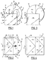
- Figures 1 and 2 schematically show the upper part of a heat exchanger body 1 of parallelepiped shape elongated in the vertical direction, of the type with brazed plates.
- This is for example the main evaporator-condenser of a double air distillation column, of the thermosiphon type, intended to vaporize liquid oxygen under atmospheric pressure or under a higher pressure, up to 5 bars absolute or more, by nitrogen condensation.
- we will refer to this example.
- the body 1 is consisting of a stack of rectangular plates 2, vertical and parallel, between which are interposed spacer waves also forming thermal fins.
- Each pair of plates 2 defines a passage of generally flat shape.
- the passages are closed by bars.
- the bars corresponding to the treated fluid are, however, removed on the upper face 3 of the body 1, and also on its lower face.
- the exchanger thus operates as a thermosyphon, with an upward circulation of vaporized oxygen, causing liquid oxygen.
- the two-phase mixture leaves the body 2 through its upper face 3.
- the closing bars are also arranged so as to leave free, on the vertical lateral faces of the body 1, horizontal rows of nitrogen inlet / outlet windows. These windows are capped by inlet / outlet boxes of generally cylindrical shape, such as box 4 shown in the drawing, provided at the upper part of the body and serving for the entry of nitrogen gas into the nitrogen passages, which box is supplied by a pipe 5.
- the body 1 is completed by a balloon 6 which will be described in detail below.
- the body 1 is produced by stacking plates, spacers and bars, and brazing in the oven in a single step.
- the input-output boxes such as the box 4 are attached to the body 1 by welding, as is the chamber 6.
- the balloon 6 straddles the upper edge 7 of the body 1 opposite the box 4. It has a wide opening in one piece, the edge of which, located in two planes perpendicular to each other, is connected to a seal by welding to the face 3 along the upper edge 8 of the body opposite to the edge 7, and along the other two upper edges 9 and 10 of the body 1.
- the edge of the balloon 6 is also connected to a seal by welding to the vertical face 11 of the body 1 adjacent to the face 3 on the side of the edge 7. This face 11 will be designated in the following by "front face", for more convenience.
- the three sheets 13 and 15 are welded to each other along their double insertion curve 18, which has a V shape at right angles to the top view ( Figure 2).
- the balloon 6 is completed by a front portion 19 sphero-conical. More precisely, this front part essentially comprises a truncated hemisphere 20 which extends towards the front of the limit semicircle 21 of the sheets 15 and 16, which is situated directly above the axis 14, and which overlaps the upper front edge 7 of body 1.
- a sheet 22 in three-quarters of a cone, the apex of which is on the corresponding upper front corner of the body 1, these cones having an opening such that they are tangentially connected to the hemisphere, along of a circle 23, and that they have a generator coincident with the respective edge 9, 10.
- the portions of the hemisphere located in the circles 23 are removed.
- edge of the opening of the balloon 10 is welded along the edge 8, which consists of upper end edges of the plates 2 and of closure bars, along the edges 9 and 10, consisting of upper end edges of the end plates 2A and 2B, and on the front face 11, consisting of vertical end edges of the plates 2 and closing bars.
- the two-phase oxygen leaving the face 3 of the exchanger body is collected in the balloon 6, which forms phase separator and whose the part projecting forward relative to the body 1 forms a liquid storage capacity.
- Liquid oxygen is evacuated, for recycling at the base of the exchanger, via a liquid outlet orifice 24 located near the bottom point of the balloon, while gaseous oxygen is evacuated via an outlet orifice of gas 25 located near the high point of the balloon.
- the two orifices 24 and 25 are located on the hemisphere 20.
- the balloon 6 could project from the two sides, front and rear, of the body 1.
- the sheets 13, 15 and 16 would be replaced by a single semi-cylindrical sheet of axis 17, and we would have on the rear side a balloon part identical to part 19, overlapping the edge 8 and connected on the one hand to the semi-cylindrical sheet and edges 9 and 10, on the other hand to the rear face of the body exchanger.
- the width of the balloon 6, that is to say its vertical dimension in FIG. 2 can be less than that of the body 1.
- a semi-cylindrical sheet of axis 17 or an axis parallel to this axis 17 is interposed between the parts 12 and 15 of the balloon.
- the portions of the hemisphere delimited by the semicircles 26 are removed, and the sheets 20A, 22A are welded together along these four semicircles.
- the connection of the dome 6A to the body 1 is carried out along the eight lower generatrices of the half-cones.
- the dome 6A like the balloon 6 in Figures 1 to 4, is easy to connect to a body of a parallelepiped exchanger. In addition, they are particularly resistant to internal pressures, so that they can be used in many applications where the fluid supplied or discharged through them is under pressure.
- FIGS. 5 to 7 also show a cylindrical pipe 27 for supplying or discharging the fluid, connected directly, along a circle 28, to the hemisphere 20A, this pipe being of axis X-X.
- the upper cap of the sheet 20A located in the circle 28 is then, of course, removed.
- the pipe 27 can be inclined relative to the axis XX, the more so as its diameter is smaller, the main thing being that the entire periphery of this pipe cuts the hemisphere .
- the constitution of the dome 6A offers a great freedom of stitching of the supply or evacuation pipes. This, in turn, makes it easier to connect the exchanger body to devices having a relatively small space, for example in the case of certain inter-stage compressor heat exchangers.
- a transition plate 29 in a truncated cone, of axis coincident with that of the pipe and opening equal for example to 90 °, can be connected by its small base to the pipe and by its large base at sheet 20A.
- Figures 10 and 11 show a variant 6B of the dome 6A, suitable for the case of a rectangular face 3, for example because the body 1 consists of two identical exchanger bodies welded side by side along a line vertical welding 30.
- the dome 6B is produced by dividing the dome 6A into two half-domes each comprising a quarter sphere 20B and two half-cones 22A, and by adding an additional semi-cylindrical sheet 31 connected by its axial ends to the half limit circles 32 of the sheets 20B and by its edges to the lateral edges 9 and 10 of the exchanger body.
- the shape of the chamber 6, 6A, 6B can be modified by affinity, horizontal or vertical, in one direction or the other, which transforms the circular cylinders into circular or elliptical cylinders, the ellipsoid spheres and cones into cones.
- the shape of the chamber it can be produced from a single sheet by deformation, in particular by stamping, progressive forming of the forging type, etc.
- the chamber according to the invention consists of surfaces tangent to each other along their connecting lines. This provides an advantageous continuity of the stress field which develops under the effect of pressure.
Applications Claiming Priority (2)
| Application Number | Priority Date | Filing Date | Title |
|---|---|---|---|
| FR9415619A FR2728670B1 (fr) | 1994-12-23 | 1994-12-23 | Chambre d'entree/sortie de fluide, et appareil a circulation de fluide correspondant |
| FR9415619 | 1994-12-23 |
Publications (2)
| Publication Number | Publication Date |
|---|---|
| EP0718583A1 true EP0718583A1 (de) | 1996-06-26 |
| EP0718583B1 EP0718583B1 (de) | 2000-03-08 |
Family
ID=9470219
Family Applications (1)
| Application Number | Title | Priority Date | Filing Date |
|---|---|---|---|
| EP19950402781 Expired - Lifetime EP0718583B1 (de) | 1994-12-23 | 1995-12-11 | Vorrichtung zur Zirkulation eines Fluids |
Country Status (9)
| Country | Link |
|---|---|
| US (1) | US6073685A (de) |
| EP (1) | EP0718583B1 (de) |
| JP (1) | JPH08226778A (de) |
| CN (1) | CN1133431A (de) |
| AU (1) | AU702577B2 (de) |
| CA (1) | CA2166033A1 (de) |
| DE (1) | DE69515443T2 (de) |
| FR (1) | FR2728670B1 (de) |
| ZA (1) | ZA9510625B (de) |
Cited By (3)
| Publication number | Priority date | Publication date | Assignee | Title |
|---|---|---|---|---|
| EP1001239A1 (de) * | 1998-11-16 | 2000-05-17 | Valeo Thermique Moteur S.A. | Rohrbündelwärmetauscher mit zylindrischem Gehäuse |
| FR2786859A1 (fr) | 1998-12-07 | 2000-06-09 | Air Liquide | Echangeur de chaleur a plaques pour un appareil de separation d'air |
| FR2797943A1 (fr) * | 1999-08-24 | 2001-03-02 | Air Liquide | Appareil a circulation de fluide |
Families Citing this family (4)
| Publication number | Priority date | Publication date | Assignee | Title |
|---|---|---|---|---|
| FR2789165B1 (fr) * | 1999-02-01 | 2001-03-09 | Air Liquide | Echangeur de chaleur, notamment echangeur de chaleur a plaques d'un appareil de separation d'air |
| US6832647B2 (en) * | 2002-04-02 | 2004-12-21 | Modine Manufacturing Company | Integrated condenser/separator for fuel cell exhaust gases |
| JP5563592B2 (ja) * | 2008-12-17 | 2014-07-30 | スウェップ インターナショナル アクティエボラーグ | ろう付けした熱交換器のポート開口部 |
| CN112304120B (zh) * | 2019-07-31 | 2022-08-02 | 中国石油天然气集团有限公司 | 换热器 |
Citations (2)
| Publication number | Priority date | Publication date | Assignee | Title |
|---|---|---|---|---|
| EP0010083A1 (de) * | 1978-09-29 | 1980-04-16 | United Technologies Corporation | Wassersammler und System zur Ausscheidung der Feuchtigkeit aus einem Luftstrom |
| EP0566435A1 (de) * | 1992-04-17 | 1993-10-20 | L'air Liquide, Societe Anonyme Pour L'etude Et L'exploitation Des Procedes Georges Claude | Rieselwärmetauscher und Lufttrennungseinrichtung mit einem solchen Wärmetauscher |
Family Cites Families (13)
| Publication number | Priority date | Publication date | Assignee | Title |
|---|---|---|---|---|
| US1740145A (en) * | 1926-05-06 | 1929-12-17 | Westinghouse Electric & Mfg Co | Air preheater |
| US2373099A (en) * | 1941-07-11 | 1945-04-10 | Standard Oil Co | Liquid division |
| US2364058A (en) * | 1941-10-13 | 1944-12-05 | Standard Oil Co | Liquid distribution |
| US2953110A (en) * | 1954-01-22 | 1960-09-20 | W J Fraser & Co Ltd | Reciprocally folded sheet metal structures |
| US3313343A (en) * | 1964-03-26 | 1967-04-11 | Trane Co | Heat exchange apparatus |
| US3311166A (en) * | 1964-07-02 | 1967-03-28 | Trw Inc | Heat exchanger |
| DE1901475A1 (de) * | 1969-01-14 | 1970-08-27 | Messer Griesheim Gmbh | Vorrichtung zum Verteilen einer Zweiphasenstroemung auf Plattenwaermeaustauscher |
| US3877519A (en) * | 1973-07-30 | 1975-04-15 | Gen Electric | Pressurized strongback regenerator |
| US4969507A (en) * | 1977-06-30 | 1990-11-13 | Rosenblad Axel E | Integral blow down concentrator with air-cooled surface condenser |
| US4272462A (en) * | 1980-09-11 | 1981-06-09 | The Trane Company | Liquid wetted gas cooled heat exchanger |
| US5031693A (en) * | 1990-10-31 | 1991-07-16 | Sundstrand Corporation | Jet impingement plate fin heat exchanger |
| FR2685071B1 (fr) * | 1991-12-11 | 1996-12-13 | Air Liquide | Echangeur de chaleur indirect du type a plaques. |
| US5228515A (en) * | 1992-07-31 | 1993-07-20 | Tran Hai H | Modular, compact heat exchanger |
-
1994
- 1994-12-23 FR FR9415619A patent/FR2728670B1/fr not_active Expired - Fee Related
-
1995
- 1995-12-11 EP EP19950402781 patent/EP0718583B1/de not_active Expired - Lifetime
- 1995-12-11 DE DE1995615443 patent/DE69515443T2/de not_active Expired - Fee Related
- 1995-12-13 ZA ZA9510625A patent/ZA9510625B/xx unknown
- 1995-12-14 AU AU40402/95A patent/AU702577B2/en not_active Ceased
- 1995-12-22 JP JP33464095A patent/JPH08226778A/ja active Pending
- 1995-12-22 CA CA 2166033 patent/CA2166033A1/en not_active Abandoned
- 1995-12-22 CN CN95120181A patent/CN1133431A/zh active Pending
- 1995-12-26 US US08/578,234 patent/US6073685A/en not_active Expired - Fee Related
Patent Citations (2)
| Publication number | Priority date | Publication date | Assignee | Title |
|---|---|---|---|---|
| EP0010083A1 (de) * | 1978-09-29 | 1980-04-16 | United Technologies Corporation | Wassersammler und System zur Ausscheidung der Feuchtigkeit aus einem Luftstrom |
| EP0566435A1 (de) * | 1992-04-17 | 1993-10-20 | L'air Liquide, Societe Anonyme Pour L'etude Et L'exploitation Des Procedes Georges Claude | Rieselwärmetauscher und Lufttrennungseinrichtung mit einem solchen Wärmetauscher |
Cited By (5)
| Publication number | Priority date | Publication date | Assignee | Title |
|---|---|---|---|---|
| EP1001239A1 (de) * | 1998-11-16 | 2000-05-17 | Valeo Thermique Moteur S.A. | Rohrbündelwärmetauscher mit zylindrischem Gehäuse |
| FR2785980A1 (fr) * | 1998-11-16 | 2000-05-19 | Valeo Thermique Moteur Sa | Echangeur de chaleur a faisceau de tubes contenu dans un boitier cylindrique |
| US6390186B1 (en) | 1998-11-16 | 2002-05-21 | Valeo Thermique Moteur | Heat exchanger with a bank of tubes contained in a cylindrical casing |
| FR2786859A1 (fr) | 1998-12-07 | 2000-06-09 | Air Liquide | Echangeur de chaleur a plaques pour un appareil de separation d'air |
| FR2797943A1 (fr) * | 1999-08-24 | 2001-03-02 | Air Liquide | Appareil a circulation de fluide |
Also Published As
| Publication number | Publication date |
|---|---|
| EP0718583B1 (de) | 2000-03-08 |
| ZA9510625B (en) | 1997-09-15 |
| DE69515443T2 (de) | 2000-09-21 |
| AU4040295A (en) | 1996-07-04 |
| US6073685A (en) | 2000-06-13 |
| DE69515443D1 (de) | 2000-04-13 |
| CN1133431A (zh) | 1996-10-16 |
| AU702577B2 (en) | 1999-02-25 |
| JPH08226778A (ja) | 1996-09-03 |
| CA2166033A1 (en) | 1996-06-24 |
| FR2728670B1 (fr) | 1997-03-21 |
| FR2728670A1 (fr) | 1996-06-28 |
Similar Documents
| Publication | Publication Date | Title |
|---|---|---|
| BE1010543A3 (fr) | Agencement d'une grille de retenue d'un materiau actif dans un recipient, et recipient ainsi equipe. | |
| EP0546947B1 (de) | Indirekter Plattenwärmetauscher | |
| EP0491591A1 (de) | Luftdistillationskolonne mit einer Well-cross Packung | |
| EP0718583B1 (de) | Vorrichtung zur Zirkulation eines Fluids | |
| EP0571263A1 (de) | Plattenstapel für Wärmetauscher und Verfahren zu dessen Zusammenbau | |
| EP0718582B1 (de) | Wärmeaustauscher | |
| FR2718836A1 (fr) | Echangeur de chaleur perfectionné à plaques brasées. | |
| FR3065795B1 (fr) | Echangeur de chaleur a jonction d'ondes amelioree, installation de separation d'air associee et procede de fabrication d'un tel echangeur | |
| FR2461223A1 (fr) | Echangeur de chaleur comportant un empilement de plaques | |
| FR2468458A1 (fr) | Presse a cylindres permettant de former des briquettes | |
| FR2647198A1 (fr) | Echangeur thermique a conduits a plaques | |
| FR2766906A1 (fr) | Reservoir pour fluide sous pression | |
| FR2732616A1 (fr) | Distributeur de fluides | |
| EP2781870A1 (de) | Platte für Wärmetauscher, und Wärmetauscher, in den eine solche Platte eingebaut ist | |
| FR2642142A1 (fr) | Conditionnement compact pour gaz de petrole liquefies | |
| EP1230522B1 (de) | Verdampfer-kondensator und luftzerlegungsanlage | |
| EP3861270A1 (de) | Platte für einen plattenwärmetauscher | |
| WO2021190879A1 (fr) | Échangeur de chaleur à plaques | |
| FR2676371A1 (fr) | Colonne de distillation d'air a garnissage ondule-croise. | |
| EP0553340B1 (de) | Plattenwärmetauscher | |
| FR2523287A1 (fr) | Echangeur de chaleur de type liquide-gaz en particulier pour la recuperation de la chaleur des fumees | |
| FR2471569A1 (fr) | Echangeur thermique a toles empilees | |
| FR2608130A1 (fr) | Bidon gerbable | |
| FR3130952A3 (fr) | Echangeur de chaleur à connectique fluidique améliorée | |
| FR2684970A1 (fr) | Reservoir de fluide divise en plusieurs volumes elementaires. |
Legal Events
| Date | Code | Title | Description |
|---|---|---|---|
| PUAI | Public reference made under article 153(3) epc to a published international application that has entered the european phase |
Free format text: ORIGINAL CODE: 0009012 |
|
| AK | Designated contracting states |
Kind code of ref document: A1 Designated state(s): BE DE ES GB IT NL SE |
|
| 17P | Request for examination filed |
Effective date: 19960507 |
|
| RIN1 | Information on inventor provided before grant (corrected) |
Inventor name: LEHMANN, JEAN-YVES Inventor name: GERARD, CLAUDE |
|
| 17Q | First examination report despatched |
Effective date: 19980211 |
|
| GRAG | Despatch of communication of intention to grant |
Free format text: ORIGINAL CODE: EPIDOS AGRA |
|
| GRAG | Despatch of communication of intention to grant |
Free format text: ORIGINAL CODE: EPIDOS AGRA |
|
| GRAG | Despatch of communication of intention to grant |
Free format text: ORIGINAL CODE: EPIDOS AGRA |
|
| GRAH | Despatch of communication of intention to grant a patent |
Free format text: ORIGINAL CODE: EPIDOS IGRA |
|
| GRAH | Despatch of communication of intention to grant a patent |
Free format text: ORIGINAL CODE: EPIDOS IGRA |
|
| GRAA | (expected) grant |
Free format text: ORIGINAL CODE: 0009210 |
|
| AK | Designated contracting states |
Kind code of ref document: B1 Designated state(s): BE DE ES GB IT NL SE |
|
| PG25 | Lapsed in a contracting state [announced via postgrant information from national office to epo] |
Ref country code: SE Free format text: THE PATENT HAS BEEN ANNULLED BY A DECISION OF A NATIONAL AUTHORITY Effective date: 20000308 Ref country code: NL Free format text: LAPSE BECAUSE OF FAILURE TO SUBMIT A TRANSLATION OF THE DESCRIPTION OR TO PAY THE FEE WITHIN THE PRESCRIBED TIME-LIMIT Effective date: 20000308 Ref country code: IT Free format text: LAPSE BECAUSE OF FAILURE TO SUBMIT A TRANSLATION OF THE DESCRIPTION OR TO PAY THE FEE WITHIN THE PRESCRIBED TIME-LIMIT;WARNING: LAPSES OF ITALIAN PATENTS WITH EFFECTIVE DATE BEFORE 2007 MAY HAVE OCCURRED AT ANY TIME BEFORE 2007. THE CORRECT EFFECTIVE DATE MAY BE DIFFERENT FROM THE ONE RECORDED. Effective date: 20000308 Ref country code: ES Free format text: THE PATENT HAS BEEN ANNULLED BY A DECISION OF A NATIONAL AUTHORITY Effective date: 20000308 |
|
| REF | Corresponds to: |
Ref document number: 69515443 Country of ref document: DE Date of ref document: 20000413 |
|
| GBT | Gb: translation of ep patent filed (gb section 77(6)(a)/1977) |
Effective date: 20000522 |
|
| NLV1 | Nl: lapsed or annulled due to failure to fulfill the requirements of art. 29p and 29m of the patents act | ||
| PG25 | Lapsed in a contracting state [announced via postgrant information from national office to epo] |
Ref country code: BE Free format text: LAPSE BECAUSE OF NON-PAYMENT OF DUE FEES Effective date: 20001231 |
|
| PLBE | No opposition filed within time limit |
Free format text: ORIGINAL CODE: 0009261 |
|
| STAA | Information on the status of an ep patent application or granted ep patent |
Free format text: STATUS: NO OPPOSITION FILED WITHIN TIME LIMIT |
|
| 26N | No opposition filed | ||
| BERE | Be: lapsed |
Owner name: NORDON CRYOGENIE SNC Effective date: 20001231 Owner name: S.A. L' AIR LIQUIDE POUR L'ETUDE ET L'EXPLOITATION Effective date: 20001231 |
|
| PGFP | Annual fee paid to national office [announced via postgrant information from national office to epo] |
Ref country code: GB Payment date: 20011204 Year of fee payment: 7 |
|
| PGFP | Annual fee paid to national office [announced via postgrant information from national office to epo] |
Ref country code: DE Payment date: 20011214 Year of fee payment: 7 |
|
| REG | Reference to a national code |
Ref country code: GB Ref legal event code: IF02 |
|
| PG25 | Lapsed in a contracting state [announced via postgrant information from national office to epo] |
Ref country code: GB Free format text: LAPSE BECAUSE OF NON-PAYMENT OF DUE FEES Effective date: 20021211 |
|
| PG25 | Lapsed in a contracting state [announced via postgrant information from national office to epo] |
Ref country code: DE Free format text: LAPSE BECAUSE OF NON-PAYMENT OF DUE FEES Effective date: 20030701 |
|
| GBPC | Gb: european patent ceased through non-payment of renewal fee |