EP0718486A2 - Schubumkehrvorrichtung mit perforierter Innenabdeckung für ein Strahltriebwerk - Google Patents
Schubumkehrvorrichtung mit perforierter Innenabdeckung für ein Strahltriebwerk Download PDFInfo
- Publication number
- EP0718486A2 EP0718486A2 EP95402805A EP95402805A EP0718486A2 EP 0718486 A2 EP0718486 A2 EP 0718486A2 EP 95402805 A EP95402805 A EP 95402805A EP 95402805 A EP95402805 A EP 95402805A EP 0718486 A2 EP0718486 A2 EP 0718486A2
- Authority
- EP
- European Patent Office
- Prior art keywords
- cowling
- engine
- thrust reverser
- doors
- separating partition
- Prior art date
- Legal status (The legal status is an assumption and is not a legal conclusion. Google has not performed a legal analysis and makes no representation as to the accuracy of the status listed.)
- Granted
Links
- 238000005192 partition Methods 0.000 claims abstract description 36
- 238000011144 upstream manufacturing Methods 0.000 claims description 22
- 239000011148 porous material Substances 0.000 claims description 4
- 238000004891 communication Methods 0.000 claims description 3
- 238000007789 sealing Methods 0.000 claims description 3
- 239000007789 gas Substances 0.000 description 9
- 230000002441 reversible effect Effects 0.000 description 5
- 239000000243 solution Substances 0.000 description 4
- 230000001627 detrimental effect Effects 0.000 description 2
- 238000009826 distribution Methods 0.000 description 2
- 230000000670 limiting effect Effects 0.000 description 2
- 239000000463 material Substances 0.000 description 2
- 230000036961 partial effect Effects 0.000 description 2
- 230000003068 static effect Effects 0.000 description 2
- 241001415961 Gaviidae Species 0.000 description 1
- 239000003570 air Substances 0.000 description 1
- 239000012080 ambient air Substances 0.000 description 1
- 230000000903 blocking effect Effects 0.000 description 1
- 239000002131 composite material Substances 0.000 description 1
- 238000010586 diagram Methods 0.000 description 1
- 238000010790 dilution Methods 0.000 description 1
- 239000012895 dilution Substances 0.000 description 1
- 238000006073 displacement reaction Methods 0.000 description 1
- 238000005304 joining Methods 0.000 description 1
- 238000003754 machining Methods 0.000 description 1
- 239000002184 metal Substances 0.000 description 1
- 238000000034 method Methods 0.000 description 1
- 238000000465 moulding Methods 0.000 description 1
- 230000002093 peripheral effect Effects 0.000 description 1
- 230000002829 reductive effect Effects 0.000 description 1
- 238000005303 weighing Methods 0.000 description 1
Images


Classifications
-
- F—MECHANICAL ENGINEERING; LIGHTING; HEATING; WEAPONS; BLASTING
- F02—COMBUSTION ENGINES; HOT-GAS OR COMBUSTION-PRODUCT ENGINE PLANTS
- F02K—JET-PROPULSION PLANTS
- F02K1/00—Plants characterised by the form or arrangement of the jet pipe or nozzle; Jet pipes or nozzles peculiar thereto
- F02K1/54—Nozzles having means for reversing jet thrust
- F02K1/56—Reversing jet main flow
-
- F—MECHANICAL ENGINEERING; LIGHTING; HEATING; WEAPONS; BLASTING
- F02—COMBUSTION ENGINES; HOT-GAS OR COMBUSTION-PRODUCT ENGINE PLANTS
- F02K—JET-PROPULSION PLANTS
- F02K1/00—Plants characterised by the form or arrangement of the jet pipe or nozzle; Jet pipes or nozzles peculiar thereto
- F02K1/54—Nozzles having means for reversing jet thrust
- F02K1/64—Reversing fan flow
- F02K1/70—Reversing fan flow using thrust reverser flaps or doors mounted on the fan housing
-
- F—MECHANICAL ENGINEERING; LIGHTING; HEATING; WEAPONS; BLASTING
- F05—INDEXING SCHEMES RELATING TO ENGINES OR PUMPS IN VARIOUS SUBCLASSES OF CLASSES F01-F04
- F05D—INDEXING SCHEME FOR ASPECTS RELATING TO NON-POSITIVE-DISPLACEMENT MACHINES OR ENGINES, GAS-TURBINES OR JET-PROPULSION PLANTS
- F05D2250/00—Geometry
- F05D2250/10—Two-dimensional
- F05D2250/19—Two-dimensional machined; miscellaneous
- F05D2250/191—Two-dimensional machined; miscellaneous perforated
-
- Y—GENERAL TAGGING OF NEW TECHNOLOGICAL DEVELOPMENTS; GENERAL TAGGING OF CROSS-SECTIONAL TECHNOLOGIES SPANNING OVER SEVERAL SECTIONS OF THE IPC; TECHNICAL SUBJECTS COVERED BY FORMER USPC CROSS-REFERENCE ART COLLECTIONS [XRACs] AND DIGESTS
- Y02—TECHNOLOGIES OR APPLICATIONS FOR MITIGATION OR ADAPTATION AGAINST CLIMATE CHANGE
- Y02T—CLIMATE CHANGE MITIGATION TECHNOLOGIES RELATED TO TRANSPORTATION
- Y02T50/00—Aeronautics or air transport
- Y02T50/60—Efficient propulsion technologies, e.g. for aircraft
Definitions
- the present invention relates to an improvement in thrust reversers for jet engines, with or without dilution of the main jet, intended in particular to be mounted on an aircraft.
- thrust reversers of the known type with pivoting doors hinged on a cowling surrounding the engine which reverser comprises an internal panel delimiting with said cowling a channel in which a gas flow circulates, called “jet engine channel”, said doors being capable of evolving from a retracted or cruising position, in which they are in the extension of the cowling and allow a circulation of said flow in direct jet, in a deployed or inversion position in which they at least partially close off the jet engine channel and release a flow deflection well, formed in the inner panel of the cowling, allowing the flow to escape radially outward and upstream of the engine.
- jet engine channel a channel in which a gas flow circulates
- doors of this type are generally equipped at their upstream end with a deflection spoiler and they have an internal panel which, in the retracted position of the doors, is spaced radially outward relative to the surface of the internal panel of the cowling, a free space or cavity being thus formed, at the level of the deflection well, between each door and the external limit of the gas flow stream determined by the surface of the internal panel of the cowling.
- FR-A-2 506 843 and FR-A-2 559 838 describe such devices.
- the present invention provides a simple and economical solution, consisting in separating the cavity of the gas flow stream by a separating partition, secured to the internal panel of the cowling and pierced with openings putting said cavity in communication with the channel of the jet engine.
- the separating partition is fixed and advantageously aligned with the surface of the internal partition of the cowling, thus merging with the theoretical envelope of perfect aerodynamic delimitation of the stream of the flow of gases circulating in direct jet.
- the separating partition which extends over part of the deflection well from the upstream edge thereof, may extend over the entire area of the cavity.
- the openings drilled in the separating partition will advantageously have the form of oblong slots, these slots making it possible to act on the circumferential distribution of the flows deflected by the deployed reverser by providing a density of lights per unit of area variable according to the zones.
- the lights may be, in some cases oriented either parallel to the axis of the engine, or transversely, or even at an angle with respect thereto.
- the total area of the openings in the partition must be calculated in such a way that, despite the presence of the partition partially blocking the deflection well, the reverse flow can be removed without restriction.
- the pressure prevailing in the cavity is the same as that prevailing in the channel of the jet engine, which is made possible at both by the existence of the openings in the separating partition and by the fact that the fixed cowling part comprises, in the vicinity of the upstream edge of the deflection well, a sealing means with which the internal panel of the door cooperates when it is in the closed position in order to isolate the cavity from the ambient environment outside the engine.
- FIG. 1 of the accompanying drawings shows, for the sake of clarity, a known example of embodiment of a door reverser, composed of three main parts, namely, from upstream to downstream, with reference to the direction of the flow of engine gas in direct jet (not deflected): a fixed upstream part 1, located in the extension of the external wall of the engine channel which has been materialized in XX ′ longitudinal axis, movable doors 2 and a fixed rear ferrule 3.
- the upstream fixed part 1 comprises an external nacelle panel 4, an internal panel 5 externally limiting the flow of the gas flow from the engine symbolized by the arrow 15 and an upstream structure 6 composed either of a front frame, or of a front box, which ensures the joining of said panels 4 and 5.
- the upstream structure 6 also serves as a support for the device for controlling the movements of the movable doors 2 which are pivotally articulated on pivots P secured to the fixed part of the engine cowling.
- the number of doors may vary depending on the particular application; for example two, three or four doors forming an annular assembly, possibly in cooperation with a fixed part, depending on the method of mounting the propulsion assembly constituted by the turbojet engine on the aircraft.
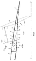
- FIG. 2 shows, in a perspective view, an exemplary embodiment of a thrust reverser according to the invention in an application comprising two doors, each door being associated with a displacement control means such as a jack 17. In the open position, the doors 2 release in the engine cowling a deflection well indicated in D ' , the difference between well D 'of the invention and well D of the prior art being explained below.
- the deflection well D is limited, on the downstream side, by the front part 7 of the internal wall 11 of the door 2 and, on the upstream side, by the surface L parallel to the general direction of the door 2 in the open position, and passing through the downstream end of a deflection edge 8 by which the fixed part 1 of the cowling ends, said deflection edge 8 being fixed under the upstream structure 6.
- Each door 2 is composed of an external panel 9 which is placed, in the direct jet position, in the extension of the external panel 4 of the upstream fixed part 1 to form the continuous aerodynamic wall limiting the flow outside the engine shown by arrow 10; an internal panel 11 and an internal structure 12, ensuring the connection between the panels 9 and 11.
- the door 2 is completed at its upstream end by a deflector spoiler 13 intended to channel the reverse flow when the reverser is is in the reverse thrust position, that is to say with the door 2 in the open or deployed position ( Figure 2 and dotted position in Figure 1).
- a deflector spoiler 13 intended to channel the reverse flow when the reverser is is in the reverse thrust position, that is to say with the door 2 in the open or deployed position ( Figure 2 and dotted position in Figure 1).
- the front part 7 of the internal panel 11 move apart, in a radial outer direction, of a theoretical surface represented by line 14, corresponding to the theoretical envelope of perfect continuous aerodynamic delimitation of the stream of gas flow in direct jet, internal to the engine, represented by arrow 15.
- a cavity 16 is thus formed on the inner side of the door 2 when it is in the closed position. In direct jet mode, part of the flow penetrates the cavity 16, thus creating a distortion of the flow and disturbances in the flow. This results in aerodynamic losses which are detrimental to direct thrust operation.
- FIGS. 2, 3 and 4a to 4d in which the members similar to those of FIG. 1 are designated by the same reference numbers.
- a separating partition 28 integral with the internal panel 5 extends between the internal channel CA where the gas stream flows in direct jet 15 and the cavity 16.
- This partition 28 is fixed and merges with the aforementioned line 14, in the extension of the internal partition 5 of the cowling and of the downstream part of the inner panel 11 of the door or of the inner panel of the rear ferrule 3.
- the partition 28 covers only part of the cavity 16 but it could extend over the entire length of the latter. In any event, it only extends over a part of the deflection well D ′, thus providing a passage section sufficient for the reverse flow.
- the downstream end 29 of the partition 28 ends in a rounded shape, or this downstream end can be provided with a mechanical device serving to improve aerodynamic performance, such as a movable part, taking for example the shape a movable lip.
- a mechanical device can be operated by articulated members, controlled by the actuator actuator 17 of the doors ( Figure 2).
- the separating partition 28 is pierced with openings 19 which communicate the space of the internal channel CA with the interior of the cavity 16, so that it can be considered that the upstream edge of the deflection well D 'corresponds not at the surface L, as in FIG. 1, but at the surface L ′, parallel to L and passing through the upstream edge of the most upstream opening 19a of the separating partition 28. It is understood that, with respect to the prior art illustrated in FIG.
- the fixed structure of the cowling comprises a part 32 provided with a seal sealing 18 located substantially at the level of the upstream edge of the deflection well D 'and against which the front part 7 of the internal door panel rests in the retracted or closed door position, in order to isolate the cavity 16 from the ambient environment EX outside the engine.
- the cavity 16 is isolated from the external space EX surrounding the engine and, when the engine operates in direct jet (doors closed), the static pressure in the cavity 16 is about the same as the pressure prevailing in the internal CA channel. Therefore, the flow of the gas stream in direct jet 15 in said channel CA is not affected by the presence of the openings 19.
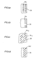
- the shape, the arrangement and the number of openings 19 in the separating partition 28 can be any and will depend on the aerodynamic performance to be respected.
- a preferred shape for the openings 19 will be that of oblong slots, the major axis of which may be parallel to the axis of the engine as shown in 19a in FIG. 4a or transverse to the axis of the engine as shown in 19b in the figure. 4b.
- the major axis of the lights may be at an angle relative to said axis, as shown in FIG. 4c, possibly with an alternation of oblong lights 19c 1 and shorter lights 19c 2 .
- the openings will be obtained either by machining in the case of metal partitions, or by molding or rerouting in the case of composite materials.
Landscapes
- Engineering & Computer Science (AREA)
- Chemical & Material Sciences (AREA)
- Combustion & Propulsion (AREA)
- Mechanical Engineering (AREA)
- General Engineering & Computer Science (AREA)
- Superstructure Of Vehicle (AREA)
- Structures Of Non-Positive Displacement Pumps (AREA)
Applications Claiming Priority (2)
| Application Number | Priority Date | Filing Date | Title |
|---|---|---|---|
| FR9415389 | 1994-12-21 | ||
| FR9415389A FR2728626B1 (fr) | 1994-12-21 | 1994-12-21 | Inverseur de poussee pour moteur a reaction a bord de deviation amenage |
Publications (3)
| Publication Number | Publication Date |
|---|---|
| EP0718486A2 true EP0718486A2 (de) | 1996-06-26 |
| EP0718486A3 EP0718486A3 (de) | 1997-06-04 |
| EP0718486B1 EP0718486B1 (de) | 2001-11-14 |
Family
ID=9470043
Family Applications (1)
| Application Number | Title | Priority Date | Filing Date |
|---|---|---|---|
| EP95402805A Expired - Lifetime EP0718486B1 (de) | 1994-12-21 | 1995-12-13 | Schubumkehrvorrichtung mit perforierter Innenabdeckung für ein Strahltriebwerk |
Country Status (4)
| Country | Link |
|---|---|
| US (1) | US5716025A (de) |
| EP (1) | EP0718486B1 (de) |
| DE (1) | DE69523877T2 (de) |
| FR (1) | FR2728626B1 (de) |
Families Citing this family (13)
| Publication number | Priority date | Publication date | Assignee | Title |
|---|---|---|---|---|
| US5875995A (en) * | 1997-05-20 | 1999-03-02 | Rohr, Inc. | Pivoting door type thrust reverser with deployable members for efflux control and flow separation |
| US6233920B1 (en) * | 1999-02-01 | 2001-05-22 | Stage Iii Technologies, L.C. | Contoured thrust reverser and lobed nozzle noise suppressor for gas turbine engines |
| US8015797B2 (en) | 2006-09-21 | 2011-09-13 | Jean-Pierre Lair | Thrust reverser nozzle for a turbofan gas turbine engine |
| US8052085B2 (en) | 2007-11-16 | 2011-11-08 | The Nordam Group, Inc. | Thrust reverser for a turbofan gas turbine engine |
| US8051639B2 (en) * | 2007-11-16 | 2011-11-08 | The Nordam Group, Inc. | Thrust reverser |
| US8091827B2 (en) | 2007-11-16 | 2012-01-10 | The Nordam Group, Inc. | Thrust reverser door |
| US7735778B2 (en) | 2007-11-16 | 2010-06-15 | Pratt & Whitney Canada Corp. | Pivoting fairings for a thrust reverser |
| US8172175B2 (en) | 2007-11-16 | 2012-05-08 | The Nordam Group, Inc. | Pivoting door thrust reverser for a turbofan gas turbine engine |
| US8052086B2 (en) | 2007-11-16 | 2011-11-08 | The Nordam Group, Inc. | Thrust reverser door |
| FR3006378B1 (fr) * | 2013-05-29 | 2015-05-15 | Aircelle Sa | Nacelle de turboreacteur comportant un dispositif d'inversion de pousse a portes, comprenant des flancs interieurs sur les cotes de l'ouverture |
| US9951719B2 (en) | 2015-04-13 | 2018-04-24 | United Technologies Corporation | Combined inlet laminar and thrust reverser cascade efflux flow control system |
| US20180362171A1 (en) * | 2017-06-15 | 2018-12-20 | Donald Butler Curchod | Advanced drag reduction system for jet aircraft |
| US11155343B2 (en) * | 2018-12-17 | 2021-10-26 | The Boeing Company | Brake systems for aircraft and related methods |
Citations (6)
| Publication number | Priority date | Publication date | Assignee | Title |
|---|---|---|---|---|
| FR2506843A1 (fr) | 1981-05-29 | 1982-12-03 | Hurel Dubois Avions | Dispositif d'inversion de poussee pour turboreacteur d'avion |
| FR2559838A1 (fr) | 1984-02-21 | 1985-08-23 | Hurel Dubois Avions | Procede et dispositif permettant le controle du jet inverse dans les moteurs a reaction a inverseur de poussee |
| FR2627807A1 (fr) | 1988-02-25 | 1989-09-01 | Hispano Suiza Sa | Inverseur de poussee de turboreacteur a double flux equipe de bords de deviation munis de levres mobiles |
| FR2629135A1 (fr) | 1988-03-28 | 1989-09-29 | Gen Electric | Inverseur de poussee pour reacteur a double flux |
| FR2634251A1 (fr) | 1988-07-18 | 1990-01-19 | Hispano Suiza Sa | Inverseur de poussee de turboreacteur a double flux equipe de bords de deviation mobiles |
| FR2635825A1 (fr) | 1988-08-29 | 1990-03-02 | Hurel Dubois Avions | Inverseur de poussee pour moteur a reaction de type a portes equipees de volets auxiliaires |
Family Cites Families (9)
| Publication number | Priority date | Publication date | Assignee | Title |
|---|---|---|---|---|
| US2847823A (en) * | 1955-03-15 | 1958-08-19 | Curtiss Wright Corp | Reverse thrust nozzle construction |
| US3667680A (en) * | 1970-04-24 | 1972-06-06 | Boeing Co | Jet engine exhaust nozzle system |
| US4093122A (en) * | 1976-11-03 | 1978-06-06 | Rohr Industries, Inc. | Integrated divergent exhaust nozzle thrust reverser |
| US4182501A (en) * | 1977-03-04 | 1980-01-08 | Astech | Thrust reverser for jet engine forming active extension of jet tube |
| FR2382594A1 (fr) * | 1977-03-04 | 1978-09-29 | Hurel Dubois Avions | Inverseur de poussee pour moteur a reaction |
| GB2117720A (en) * | 1981-02-28 | 1983-10-19 | Rolls Royce | Gas turbine engine having a thrust spoiler |
| US5224342A (en) * | 1992-02-13 | 1993-07-06 | Lair Jean Pierre | Latching and sealing arrangement for jet engine thrust reverser |
| FR2695436B3 (fr) * | 1992-09-08 | 1994-12-02 | Hurel Dubois Avions | Porte d'inverseur de poussée comportant des moyens d'amortissement acoustique. |
| US5372006A (en) * | 1993-02-08 | 1994-12-13 | Aeronautical Concept Of Exhaust, Ltd. | Turbine engine equipped with thrust reverser |
-
1994
- 1994-12-21 FR FR9415389A patent/FR2728626B1/fr not_active Expired - Fee Related
-
1995
- 1995-12-13 EP EP95402805A patent/EP0718486B1/de not_active Expired - Lifetime
- 1995-12-13 DE DE69523877T patent/DE69523877T2/de not_active Expired - Fee Related
- 1995-12-14 US US08/572,612 patent/US5716025A/en not_active Expired - Lifetime
Patent Citations (6)
| Publication number | Priority date | Publication date | Assignee | Title |
|---|---|---|---|---|
| FR2506843A1 (fr) | 1981-05-29 | 1982-12-03 | Hurel Dubois Avions | Dispositif d'inversion de poussee pour turboreacteur d'avion |
| FR2559838A1 (fr) | 1984-02-21 | 1985-08-23 | Hurel Dubois Avions | Procede et dispositif permettant le controle du jet inverse dans les moteurs a reaction a inverseur de poussee |
| FR2627807A1 (fr) | 1988-02-25 | 1989-09-01 | Hispano Suiza Sa | Inverseur de poussee de turboreacteur a double flux equipe de bords de deviation munis de levres mobiles |
| FR2629135A1 (fr) | 1988-03-28 | 1989-09-29 | Gen Electric | Inverseur de poussee pour reacteur a double flux |
| FR2634251A1 (fr) | 1988-07-18 | 1990-01-19 | Hispano Suiza Sa | Inverseur de poussee de turboreacteur a double flux equipe de bords de deviation mobiles |
| FR2635825A1 (fr) | 1988-08-29 | 1990-03-02 | Hurel Dubois Avions | Inverseur de poussee pour moteur a reaction de type a portes equipees de volets auxiliaires |
Also Published As
| Publication number | Publication date |
|---|---|
| FR2728626B1 (fr) | 1998-03-06 |
| EP0718486B1 (de) | 2001-11-14 |
| US5716025A (en) | 1998-02-10 |
| DE69523877T2 (de) | 2002-07-04 |
| FR2728626A1 (fr) | 1996-06-28 |
| DE69523877D1 (de) | 2001-12-20 |
| EP0718486A3 (de) | 1997-06-04 |
Similar Documents
| Publication | Publication Date | Title |
|---|---|---|
| CA2002466C (fr) | Inverseur de poussee de turboreacteur muni de portes a mini-tuyere de deviation du flux inverse | |
| EP0757170B1 (de) | Schubumkehrvorrichtung für ein Strahltriebwerk, mit einer Klappe | |
| CA2213049C (fr) | Inverseur de poussee de turboreacteur a portes formant ecopes | |
| EP0777045B1 (de) | Schubumkehrvorrichtung mit Klappen und an dem Hinterteil verbundenen Hilfsklappen | |
| EP0718486B1 (de) | Schubumkehrvorrichtung mit perforierter Innenabdeckung für ein Strahltriebwerk | |
| EP0310497B1 (de) | Schubumkehrvorrichtung für Strahltriebwerke mittels Klappen mit fluchtrechten Innenflächen | |
| CA2225608C (fr) | Inverseur de poussee de turboreacteur a double flux a coquilles aval | |
| EP0828934B1 (de) | Schubumkehrvorrichtung mit zwei klappen | |
| EP0836000B1 (de) | Klappenschubumkehrvorrichtung mit geregeltem Leckstrom | |
| EP0357494B1 (de) | Schubumkehrvorrichtung mit Hilfsklappen für einen Strahlmotor | |
| WO1992005356A1 (fr) | Inverseur de poussee de turboreacteur, a portes associees a un panneau amont | |
| EP0806563B1 (de) | Klappen mit Leitflächen für eine Schubumkehrvorrichtung eines Bläsertriebwerkes | |
| EP0414609A1 (de) | Kaskadenschubumkehrvorrichtung ohne Schiebehaube für ein Strahltriebwerk | |
| EP0542624A1 (de) | Konfiguration einer Schubumkehrvorrichtung für ein Zweistrahltreibwerk | |
| EP0413635B1 (de) | Schubumkehrvorrichtung für ein Strahltriebwerk | |
| CA2858740A1 (fr) | Joint d'etancheite pour pylone et nacelle de turboreacteur et ensemble de pylone et nacelle de turboreacteur incorporant un tel joint d'etancheite | |
| FR2738597A1 (fr) | Inverseur de poussee de turboreacteur a portes associees a un panneau primaire | |
| FR2730764A1 (fr) | Inverseur de poussee a portes associees a un panneau aval | |
| EP3489499A1 (de) | Innenstruktur eines primären ausstossrohrs | |
| FR3125093A1 (fr) | Bielle pour nacelle de turbomachine | |
| FR2526872A1 (fr) | Inverseur de poussee a porte notamment pour moteur d'avion a reaction | |
| WO2021170932A1 (fr) | Inverseur de poussée comprenant un bord de déviation traité acoustiquement | |
| EP0150649A1 (de) | Zweistrahltriebwerk mit Schubumkehrvorrichtung |
Legal Events
| Date | Code | Title | Description |
|---|---|---|---|
| PUAI | Public reference made under article 153(3) epc to a published international application that has entered the european phase |
Free format text: ORIGINAL CODE: 0009012 |
|
| AK | Designated contracting states |
Kind code of ref document: A2 Designated state(s): DE GB |
|
| PUAL | Search report despatched |
Free format text: ORIGINAL CODE: 0009013 |
|
| AK | Designated contracting states |
Kind code of ref document: A3 Designated state(s): DE GB |
|
| 17P | Request for examination filed |
Effective date: 19971113 |
|
| GRAG | Despatch of communication of intention to grant |
Free format text: ORIGINAL CODE: EPIDOS AGRA |
|
| 17Q | First examination report despatched |
Effective date: 20010130 |
|
| GRAG | Despatch of communication of intention to grant |
Free format text: ORIGINAL CODE: EPIDOS AGRA |
|
| GRAH | Despatch of communication of intention to grant a patent |
Free format text: ORIGINAL CODE: EPIDOS IGRA |
|
| GRAH | Despatch of communication of intention to grant a patent |
Free format text: ORIGINAL CODE: EPIDOS IGRA |
|
| GRAA | (expected) grant |
Free format text: ORIGINAL CODE: 0009210 |
|
| AK | Designated contracting states |
Kind code of ref document: B1 Designated state(s): DE GB |
|
| REF | Corresponds to: |
Ref document number: 69523877 Country of ref document: DE Date of ref document: 20011220 |
|
| PGFP | Annual fee paid to national office [announced via postgrant information from national office to epo] |
Ref country code: DE Payment date: 20011228 Year of fee payment: 7 |
|
| REG | Reference to a national code |
Ref country code: GB Ref legal event code: IF02 |
|
| RAP2 | Party data changed (patent owner data changed or rights of a patent transferred) |
Owner name: HUREL-HISPANO MEUDON |
|
| PGFP | Annual fee paid to national office [announced via postgrant information from national office to epo] |
Ref country code: GB Payment date: 20020205 Year of fee payment: 7 |
|
| GBT | Gb: translation of ep patent filed (gb section 77(6)(a)/1977) |
Effective date: 20020417 |
|
| PLBE | No opposition filed within time limit |
Free format text: ORIGINAL CODE: 0009261 |
|
| STAA | Information on the status of an ep patent application or granted ep patent |
Free format text: STATUS: NO OPPOSITION FILED WITHIN TIME LIMIT |
|
| 26N | No opposition filed | ||
| PG25 | Lapsed in a contracting state [announced via postgrant information from national office to epo] |
Ref country code: GB Free format text: LAPSE BECAUSE OF NON-PAYMENT OF DUE FEES Effective date: 20021213 |
|
| PG25 | Lapsed in a contracting state [announced via postgrant information from national office to epo] |
Ref country code: DE Free format text: LAPSE BECAUSE OF NON-PAYMENT OF DUE FEES Effective date: 20030701 |
|
| GBPC | Gb: european patent ceased through non-payment of renewal fee |
Effective date: 20021213 |