EP0716838B1 - Prosthesis with articulating surface stress reducing contact edge - Google Patents
Prosthesis with articulating surface stress reducing contact edge Download PDFInfo
- Publication number
- EP0716838B1 EP0716838B1 EP95118660A EP95118660A EP0716838B1 EP 0716838 B1 EP0716838 B1 EP 0716838B1 EP 95118660 A EP95118660 A EP 95118660A EP 95118660 A EP95118660 A EP 95118660A EP 0716838 B1 EP0716838 B1 EP 0716838B1
- Authority
- EP
- European Patent Office
- Prior art keywords
- edge
- prothesis
- region
- bearing
- platform
- Prior art date
- Legal status (The legal status is an assumption and is not a legal conclusion. Google has not performed a legal analysis and makes no representation as to the accuracy of the status listed.)
- Expired - Lifetime
Links
- 229910052751 metal Inorganic materials 0.000 claims description 9
- 239000002184 metal Substances 0.000 claims description 9
- 229920001169 thermoplastic Polymers 0.000 claims description 9
- 239000004416 thermosoftening plastic Substances 0.000 claims description 9
- 239000004033 plastic Substances 0.000 description 16
- 229920003023 plastic Polymers 0.000 description 16
- 230000000694 effects Effects 0.000 description 8
- 230000008859 change Effects 0.000 description 5
- 230000013011 mating Effects 0.000 description 5
- 210000003127 knee Anatomy 0.000 description 4
- 238000013150 knee replacement Methods 0.000 description 4
- 239000000463 material Substances 0.000 description 4
- 210000001503 joint Anatomy 0.000 description 3
- 210000002967 posterior cruciate ligament Anatomy 0.000 description 3
- 230000000717 retained effect Effects 0.000 description 3
- 229920010741 Ultra High Molecular Weight Polyethylene (UHMWPE) Polymers 0.000 description 2
- 230000000254 damaging effect Effects 0.000 description 2
- 210000002391 femur head Anatomy 0.000 description 2
- 210000001624 hip Anatomy 0.000 description 2
- 210000003041 ligament Anatomy 0.000 description 2
- 230000033001 locomotion Effects 0.000 description 2
- 230000002093 peripheral effect Effects 0.000 description 2
- 241001465754 Metazoa Species 0.000 description 1
- 229910001069 Ti alloy Inorganic materials 0.000 description 1
- 239000004699 Ultra-high molecular weight polyethylene Substances 0.000 description 1
- WAIPAZQMEIHHTJ-UHFFFAOYSA-N [Cr].[Co] Chemical class [Cr].[Co] WAIPAZQMEIHHTJ-UHFFFAOYSA-N 0.000 description 1
- 230000002411 adverse Effects 0.000 description 1
- 210000003423 ankle Anatomy 0.000 description 1
- 230000003466 anti-cipated effect Effects 0.000 description 1
- 238000013459 approach Methods 0.000 description 1
- 230000008901 benefit Effects 0.000 description 1
- 239000000919 ceramic Substances 0.000 description 1
- 230000006835 compression Effects 0.000 description 1
- 238000007906 compression Methods 0.000 description 1
- 238000010276 construction Methods 0.000 description 1
- 230000001419 dependent effect Effects 0.000 description 1
- 210000001513 elbow Anatomy 0.000 description 1
- 210000003811 finger Anatomy 0.000 description 1
- 210000004394 hip joint Anatomy 0.000 description 1
- 238000011540 hip replacement Methods 0.000 description 1
- 230000006872 improvement Effects 0.000 description 1
- 230000001788 irregular Effects 0.000 description 1
- 238000004519 manufacturing process Methods 0.000 description 1
- 239000007769 metal material Substances 0.000 description 1
- 150000002739 metals Chemical class 0.000 description 1
- 239000000203 mixture Substances 0.000 description 1
- 238000012986 modification Methods 0.000 description 1
- 230000004048 modification Effects 0.000 description 1
- 230000008447 perception Effects 0.000 description 1
- 230000009467 reduction Effects 0.000 description 1
- 230000004044 response Effects 0.000 description 1
- 210000002832 shoulder Anatomy 0.000 description 1
- 210000002303 tibia Anatomy 0.000 description 1
- 210000003371 toe Anatomy 0.000 description 1
- 229920000785 ultra high molecular weight polyethylene Polymers 0.000 description 1
Images


Classifications
-
- A—HUMAN NECESSITIES
- A61—MEDICAL OR VETERINARY SCIENCE; HYGIENE
- A61F—FILTERS IMPLANTABLE INTO BLOOD VESSELS; PROSTHESES; DEVICES PROVIDING PATENCY TO, OR PREVENTING COLLAPSING OF, TUBULAR STRUCTURES OF THE BODY, e.g. STENTS; ORTHOPAEDIC, NURSING OR CONTRACEPTIVE DEVICES; FOMENTATION; TREATMENT OR PROTECTION OF EYES OR EARS; BANDAGES, DRESSINGS OR ABSORBENT PADS; FIRST-AID KITS
- A61F2/00—Filters implantable into blood vessels; Prostheses, i.e. artificial substitutes or replacements for parts of the body; Appliances for connecting them with the body; Devices providing patency to, or preventing collapsing of, tubular structures of the body, e.g. stents
- A61F2/02—Prostheses implantable into the body
- A61F2/30—Joints
- A61F2/38—Joints for elbows or knees
-
- A—HUMAN NECESSITIES
- A61—MEDICAL OR VETERINARY SCIENCE; HYGIENE
- A61F—FILTERS IMPLANTABLE INTO BLOOD VESSELS; PROSTHESES; DEVICES PROVIDING PATENCY TO, OR PREVENTING COLLAPSING OF, TUBULAR STRUCTURES OF THE BODY, e.g. STENTS; ORTHOPAEDIC, NURSING OR CONTRACEPTIVE DEVICES; FOMENTATION; TREATMENT OR PROTECTION OF EYES OR EARS; BANDAGES, DRESSINGS OR ABSORBENT PADS; FIRST-AID KITS
- A61F2/00—Filters implantable into blood vessels; Prostheses, i.e. artificial substitutes or replacements for parts of the body; Appliances for connecting them with the body; Devices providing patency to, or preventing collapsing of, tubular structures of the body, e.g. stents
- A61F2/02—Prostheses implantable into the body
- A61F2/30—Joints
- A61F2/30767—Special external or bone-contacting surface, e.g. coating for improving bone ingrowth
-
- A—HUMAN NECESSITIES
- A61—MEDICAL OR VETERINARY SCIENCE; HYGIENE
- A61F—FILTERS IMPLANTABLE INTO BLOOD VESSELS; PROSTHESES; DEVICES PROVIDING PATENCY TO, OR PREVENTING COLLAPSING OF, TUBULAR STRUCTURES OF THE BODY, e.g. STENTS; ORTHOPAEDIC, NURSING OR CONTRACEPTIVE DEVICES; FOMENTATION; TREATMENT OR PROTECTION OF EYES OR EARS; BANDAGES, DRESSINGS OR ABSORBENT PADS; FIRST-AID KITS
- A61F2/00—Filters implantable into blood vessels; Prostheses, i.e. artificial substitutes or replacements for parts of the body; Appliances for connecting them with the body; Devices providing patency to, or preventing collapsing of, tubular structures of the body, e.g. stents
- A61F2/02—Prostheses implantable into the body
- A61F2/30—Joints
- A61F2/38—Joints for elbows or knees
- A61F2/3868—Joints for elbows or knees with sliding tibial bearing
-
- A—HUMAN NECESSITIES
- A61—MEDICAL OR VETERINARY SCIENCE; HYGIENE
- A61F—FILTERS IMPLANTABLE INTO BLOOD VESSELS; PROSTHESES; DEVICES PROVIDING PATENCY TO, OR PREVENTING COLLAPSING OF, TUBULAR STRUCTURES OF THE BODY, e.g. STENTS; ORTHOPAEDIC, NURSING OR CONTRACEPTIVE DEVICES; FOMENTATION; TREATMENT OR PROTECTION OF EYES OR EARS; BANDAGES, DRESSINGS OR ABSORBENT PADS; FIRST-AID KITS
- A61F2/00—Filters implantable into blood vessels; Prostheses, i.e. artificial substitutes or replacements for parts of the body; Appliances for connecting them with the body; Devices providing patency to, or preventing collapsing of, tubular structures of the body, e.g. stents
- A61F2/02—Prostheses implantable into the body
- A61F2/30—Joints
- A61F2002/30001—Additional features of subject-matter classified in A61F2/28, A61F2/30 and subgroups thereof
- A61F2002/30003—Material related properties of the prosthesis or of a coating on the prosthesis
- A61F2002/3006—Properties of materials and coating materials
- A61F2002/30065—Properties of materials and coating materials thermoplastic, i.e. softening or fusing when heated, and hardening and becoming rigid again when cooled
-
- A—HUMAN NECESSITIES
- A61—MEDICAL OR VETERINARY SCIENCE; HYGIENE
- A61F—FILTERS IMPLANTABLE INTO BLOOD VESSELS; PROSTHESES; DEVICES PROVIDING PATENCY TO, OR PREVENTING COLLAPSING OF, TUBULAR STRUCTURES OF THE BODY, e.g. STENTS; ORTHOPAEDIC, NURSING OR CONTRACEPTIVE DEVICES; FOMENTATION; TREATMENT OR PROTECTION OF EYES OR EARS; BANDAGES, DRESSINGS OR ABSORBENT PADS; FIRST-AID KITS
- A61F2/00—Filters implantable into blood vessels; Prostheses, i.e. artificial substitutes or replacements for parts of the body; Appliances for connecting them with the body; Devices providing patency to, or preventing collapsing of, tubular structures of the body, e.g. stents
- A61F2/02—Prostheses implantable into the body
- A61F2/30—Joints
- A61F2002/30001—Additional features of subject-matter classified in A61F2/28, A61F2/30 and subgroups thereof
- A61F2002/30108—Shapes
- A61F2002/30199—Three-dimensional shapes
- A61F2002/30205—Three-dimensional shapes conical
-
- A—HUMAN NECESSITIES
- A61—MEDICAL OR VETERINARY SCIENCE; HYGIENE
- A61F—FILTERS IMPLANTABLE INTO BLOOD VESSELS; PROSTHESES; DEVICES PROVIDING PATENCY TO, OR PREVENTING COLLAPSING OF, TUBULAR STRUCTURES OF THE BODY, e.g. STENTS; ORTHOPAEDIC, NURSING OR CONTRACEPTIVE DEVICES; FOMENTATION; TREATMENT OR PROTECTION OF EYES OR EARS; BANDAGES, DRESSINGS OR ABSORBENT PADS; FIRST-AID KITS
- A61F2/00—Filters implantable into blood vessels; Prostheses, i.e. artificial substitutes or replacements for parts of the body; Appliances for connecting them with the body; Devices providing patency to, or preventing collapsing of, tubular structures of the body, e.g. stents
- A61F2/02—Prostheses implantable into the body
- A61F2/30—Joints
- A61F2002/30001—Additional features of subject-matter classified in A61F2/28, A61F2/30 and subgroups thereof
- A61F2002/30316—The prosthesis having different structural features at different locations within the same prosthesis; Connections between prosthetic parts; Special structural features of bone or joint prostheses not otherwise provided for
- A61F2002/30329—Connections or couplings between prosthetic parts, e.g. between modular parts; Connecting elements
- A61F2002/30331—Connections or couplings between prosthetic parts, e.g. between modular parts; Connecting elements made by longitudinally pushing a protrusion into a complementarily-shaped recess, e.g. held by friction fit
- A61F2002/30332—Conically- or frustoconically-shaped protrusion and recess
-
- A—HUMAN NECESSITIES
- A61—MEDICAL OR VETERINARY SCIENCE; HYGIENE
- A61F—FILTERS IMPLANTABLE INTO BLOOD VESSELS; PROSTHESES; DEVICES PROVIDING PATENCY TO, OR PREVENTING COLLAPSING OF, TUBULAR STRUCTURES OF THE BODY, e.g. STENTS; ORTHOPAEDIC, NURSING OR CONTRACEPTIVE DEVICES; FOMENTATION; TREATMENT OR PROTECTION OF EYES OR EARS; BANDAGES, DRESSINGS OR ABSORBENT PADS; FIRST-AID KITS
- A61F2/00—Filters implantable into blood vessels; Prostheses, i.e. artificial substitutes or replacements for parts of the body; Appliances for connecting them with the body; Devices providing patency to, or preventing collapsing of, tubular structures of the body, e.g. stents
- A61F2/02—Prostheses implantable into the body
- A61F2/30—Joints
- A61F2/30767—Special external or bone-contacting surface, e.g. coating for improving bone ingrowth
- A61F2/30771—Special external or bone-contacting surface, e.g. coating for improving bone ingrowth applied in original prostheses, e.g. holes or grooves
- A61F2002/30878—Special external or bone-contacting surface, e.g. coating for improving bone ingrowth applied in original prostheses, e.g. holes or grooves with non-sharp protrusions, for instance contacting the bone for anchoring, e.g. keels, pegs, pins, posts, shanks, stems, struts
-
- A—HUMAN NECESSITIES
- A61—MEDICAL OR VETERINARY SCIENCE; HYGIENE
- A61F—FILTERS IMPLANTABLE INTO BLOOD VESSELS; PROSTHESES; DEVICES PROVIDING PATENCY TO, OR PREVENTING COLLAPSING OF, TUBULAR STRUCTURES OF THE BODY, e.g. STENTS; ORTHOPAEDIC, NURSING OR CONTRACEPTIVE DEVICES; FOMENTATION; TREATMENT OR PROTECTION OF EYES OR EARS; BANDAGES, DRESSINGS OR ABSORBENT PADS; FIRST-AID KITS
- A61F2210/00—Particular material properties of prostheses classified in groups A61F2/00 - A61F2/26 or A61F2/82 or A61F9/00 or A61F11/00 or subgroups thereof
- A61F2210/0071—Particular material properties of prostheses classified in groups A61F2/00 - A61F2/26 or A61F2/82 or A61F9/00 or A61F11/00 or subgroups thereof thermoplastic
-
- A—HUMAN NECESSITIES
- A61—MEDICAL OR VETERINARY SCIENCE; HYGIENE
- A61F—FILTERS IMPLANTABLE INTO BLOOD VESSELS; PROSTHESES; DEVICES PROVIDING PATENCY TO, OR PREVENTING COLLAPSING OF, TUBULAR STRUCTURES OF THE BODY, e.g. STENTS; ORTHOPAEDIC, NURSING OR CONTRACEPTIVE DEVICES; FOMENTATION; TREATMENT OR PROTECTION OF EYES OR EARS; BANDAGES, DRESSINGS OR ABSORBENT PADS; FIRST-AID KITS
- A61F2220/00—Fixations or connections for prostheses classified in groups A61F2/00 - A61F2/26 or A61F2/82 or A61F9/00 or A61F11/00 or subgroups thereof
- A61F2220/0025—Connections or couplings between prosthetic parts, e.g. between modular parts; Connecting elements
- A61F2220/0033—Connections or couplings between prosthetic parts, e.g. between modular parts; Connecting elements made by longitudinally pushing a protrusion into a complementary-shaped recess, e.g. held by friction fit
-
- A—HUMAN NECESSITIES
- A61—MEDICAL OR VETERINARY SCIENCE; HYGIENE
- A61F—FILTERS IMPLANTABLE INTO BLOOD VESSELS; PROSTHESES; DEVICES PROVIDING PATENCY TO, OR PREVENTING COLLAPSING OF, TUBULAR STRUCTURES OF THE BODY, e.g. STENTS; ORTHOPAEDIC, NURSING OR CONTRACEPTIVE DEVICES; FOMENTATION; TREATMENT OR PROTECTION OF EYES OR EARS; BANDAGES, DRESSINGS OR ABSORBENT PADS; FIRST-AID KITS
- A61F2230/00—Geometry of prostheses classified in groups A61F2/00 - A61F2/26 or A61F2/82 or A61F9/00 or A61F11/00 or subgroups thereof
- A61F2230/0063—Three-dimensional shapes
- A61F2230/0067—Three-dimensional shapes conical
-
- A—HUMAN NECESSITIES
- A61—MEDICAL OR VETERINARY SCIENCE; HYGIENE
- A61F—FILTERS IMPLANTABLE INTO BLOOD VESSELS; PROSTHESES; DEVICES PROVIDING PATENCY TO, OR PREVENTING COLLAPSING OF, TUBULAR STRUCTURES OF THE BODY, e.g. STENTS; ORTHOPAEDIC, NURSING OR CONTRACEPTIVE DEVICES; FOMENTATION; TREATMENT OR PROTECTION OF EYES OR EARS; BANDAGES, DRESSINGS OR ABSORBENT PADS; FIRST-AID KITS
- A61F2310/00—Prostheses classified in A61F2/28 or A61F2/30 - A61F2/44 being constructed from or coated with a particular material
- A61F2310/00005—The prosthesis being constructed from a particular material
- A61F2310/00011—Metals or alloys
- A61F2310/00023—Titanium or titanium-based alloys, e.g. Ti-Ni alloys
-
- A—HUMAN NECESSITIES
- A61—MEDICAL OR VETERINARY SCIENCE; HYGIENE
- A61F—FILTERS IMPLANTABLE INTO BLOOD VESSELS; PROSTHESES; DEVICES PROVIDING PATENCY TO, OR PREVENTING COLLAPSING OF, TUBULAR STRUCTURES OF THE BODY, e.g. STENTS; ORTHOPAEDIC, NURSING OR CONTRACEPTIVE DEVICES; FOMENTATION; TREATMENT OR PROTECTION OF EYES OR EARS; BANDAGES, DRESSINGS OR ABSORBENT PADS; FIRST-AID KITS
- A61F2310/00—Prostheses classified in A61F2/28 or A61F2/30 - A61F2/44 being constructed from or coated with a particular material
- A61F2310/00005—The prosthesis being constructed from a particular material
- A61F2310/00011—Metals or alloys
- A61F2310/00029—Cobalt-based alloys, e.g. Co-Cr alloys or Vitallium
-
- A—HUMAN NECESSITIES
- A61—MEDICAL OR VETERINARY SCIENCE; HYGIENE
- A61F—FILTERS IMPLANTABLE INTO BLOOD VESSELS; PROSTHESES; DEVICES PROVIDING PATENCY TO, OR PREVENTING COLLAPSING OF, TUBULAR STRUCTURES OF THE BODY, e.g. STENTS; ORTHOPAEDIC, NURSING OR CONTRACEPTIVE DEVICES; FOMENTATION; TREATMENT OR PROTECTION OF EYES OR EARS; BANDAGES, DRESSINGS OR ABSORBENT PADS; FIRST-AID KITS
- A61F2310/00—Prostheses classified in A61F2/28 or A61F2/30 - A61F2/44 being constructed from or coated with a particular material
- A61F2310/00389—The prosthesis being coated or covered with a particular material
- A61F2310/00592—Coating or prosthesis-covering structure made of ceramics or of ceramic-like compounds
Definitions
- This invention relates to protheses with articulating engaged surfaces, and more particularly, to articulating surfaces in which the edge of one prothesis component surface engages the surface of a mating component.
- edge wiping occurs, for example, in a hip replacement joint where the truncation of the femoral head spherical surface produces an edge that wipes at least part of the articulating surface of the ultra high molecular weight polyethylene (UHMWPe) acetabular bearing.
- UHMWPe ultra high molecular weight polyethylene
- Another example includes a prosthesis in which the edge of an articulating surface of a metallic acetabular component wipes over the surface of a plastic femoral head.
- the present inventor has observed and recognizes that where a surface edge of a first articulating surface of an articulating prothesis couple contacts an interior region of the second articulating surface of the couple, the compressive load in the second surface changes suddenly as the second surface loses contact with the first surface. This is because the compressive load produces deformation, i.e., strain, of at least one of the mating surfaces. But such strain can occur also with plastic to plastic contact and with metal to metal contact. The deformation terminates abruptly at the edge region of one surface of the couple where the edge region overlies an interior region of the other couple surface.
- FIG. 1 a representative prior art metallic-plastic articulating couple formed by prothesis 1 is illustrated showing a prothesis thermoplastic bearing 2 having a first surface 3 engaged with a second surface 5 of metal platform 4.
- the stress contour curve 8 is generally uniform as shown in region 11 except for the edge region 6.
- the stress in edge region 6 is significantly higher than the stress in interior region 11, generally about a 400% increase in stress in the material, due to the abrupt change in strain ⁇ in the edge region 6.
- the first surface 3 is metallic
- this local increase in stress is not as important since the metallic surface is strong enough to endure this large increase in stress in a prothesis environment without significant damage.
- the motions between the articulating surfaces are relatively slow and the stresses negligible in. comparison to the metal material strength properties. This results in negligible damage to the surfaces.
- a metallic edge 9 such as on platform 4 wipes a surface of a thermoplastic member, such as surface 3 of bearing 2
- a localized strain ⁇ is produced which varies to a maximum relatively abruptly and which strain produces the stress increase at curve portion 10 in region 6.
- This stress increase portion 10 will usually produce greatly increased thermoplastic surface 3 damage in joint replacement articulations as the edge 9 of the one surface such as the surface 5 of platform 4 wipes over the mating surface such as surface 3 of bearing 2.
- the problem of surface damage of the thermoplastic component is not directly related to the issue of concavity or convexity.
- the articulation is incongruent, and there is no edge wiping effect, whether the convex surface is metallic or plastic does not substantially effect the maximum contact stress in the plastic.
- the present inventor was involved in the development of a shoulder prosthesis with a plastic head which was in incongruent contact with a metallic socket, a configuration which is superior to a similar design with a metallic head and a plastic socket. Yet the perception by those of ordinary skill in this art that the convex articulating surface element must be metallic was, and is, so pervasive that the device could not, and cannot today, be brought to market. Thus the edge wiping phenomenon as discussed above is not generally understood by those of ordinary skill in the prosthetic design art.
- EP-A-0 302 850 refers to a hip prothesis including a joint having two members formed as surfaces of revolution of an approximately spherical shape. It is proposed to shape both members of the prothesis, i.e. the artificial femur head and the artificial socket of the hip joint, so that the longitudinal sections thereof can be described by Pascal's curves. Consequently, a substantial gap is formed between an edge of the artificial socket and the artificial femur head with the result that the edge portions of the prothesis members do not experience any compressive stress.
- It is the object of the invention to provide a prothesis comprising first and second members each having a substantially planar surface thereof articulating under load in contact with one another, wherein the edge wiping effect is minimized and preferably completely avoided.
- a prothesis including a joint comprising first and second members each having a surface thereof articulating under load in contact with one another, comprising a first member having a first substantially planar surface and a second member having a second surface for engaging in articulating contact the first surface, the second surface having an edge, the second surface including the edge being under compressive load with the first surface during the articulating contact, the compressive load causing the first member in the region of the second surface to exhibit a contact stress of generally a first value, the second surface having a gradual tapering region adjacent to and extending inwardly the second surface from the second surface edge a distance W so as to cause the first member to exhibit increased edge stress concentration in the region of engagement of the edge of the second surface with the first surface of a second value in the first member of no more than about twice the first value.
- the edge wiping generates a minimum of damage to the first surface especially when the first surface is of lower strength than the second surface.
- the second member is metal and the first member is a thermoplastic.
- the second surface comprises a planar portion and, at said gradual tapering region, a curvature, said curvature being tangential to said planar portion at locations interiorly from said tapering region.
- the increased edge contact stress second value is about 25% greater than the first value.
- a prothesis including a joint comprising first and second members each having a surface thereof articulating under load in contact with one another in accordance with a further embodiment, comprising a thermoplastic first member having a first surface and a second metallic member having a second surface for engaging in articulating contact the first surface, the second surface having an edge, the second surface including the edge being under compressive load with the first surface during the articulating contact, the second surface having a gradual tapering region adjacent to and extending inwardly the second surface from the edge a distance W so as to cause the first member to exhibit a gradual preferably uniform rate of change of deformation in the first surface in response to the compressive load with the second surface such that the deformation varies from essentially zero at the edge to a maximum at the planar second surface the distance W.
- Knee replacement 12 is generally of known construction, except for the improvement to be described below. The details of the various components forming replacement need not be given herein.
- Replacement 12 comprises a femoral component 14, a tibial component 16 and a patellar component 18.
- the tibial component 16 comprises a tibial bearing 20 and a tibial platform 22 which are rotatable with respect to each other about axis 24.
- the bearing 20, which is ultra high molecular weight polyethylene (UHMWPe), includes a depending conical stem 26, Fig. 3.
- the bearing 20 has a planar surface 28 for engaging a mating planar surface 32 of the tibial platform 22 and a bearing surface 30 for receiving the mating condyle of the femoral component 14.
- the bearing 20 has a peripheral edge 31.
- the platform 22 has a conical cavity 36 within conical stem 38 which is implanted in the tibia 40, Fig. 2. Cavity 36 receives the bearing 20 stem 26 along axis 24 defined by cavity 36 and stem 26.
- the bearing 20 rotates about axis 24 relative to the platform 22 via the engaged conical tibial stem 26 and platform cavity 36.
- Bearing surface 28 compressively engages platform surface 32 during this rotation.
- edges 31 of the bearing and 34 of the platform are irregular, elongated and somewhat oval in plan view. Rotation of the bearing 20 about axis 24 with respect to platform 22 results in the edge 34 portions 34' of the platform 22, Fig. 4, engaging and overlying corresponding interior portions of the planar surface 28 of the bearing 20.
- the platform 4 metallic edge 9 corner adjacent to the bearing 2 surface 3 has a relatively small radius 42.
- the relatively small radius 42 which is typically about 0.7 mm results in the compression stress contour 8 as discussed in the introductory portion.
- the increased stress concentration curve portion 10 at the region of radius 42, region 6, is undesirable.
- This stress may have a magnitude of about 400% the stress magnitude of the uniform portion 8' region 11 of the stress contour curve 8.
- the abrupt change in deformation (strain) ⁇ of the bearing 2 at the edge 9 causes undue wear of the bearing 2 as the platform 4 rotates on the bearing planar surface 3.
- Surface 3 is no longer planar at the edge region of radius 42 due to the deformation ⁇ in the softer thermoplastic bearing 2.
- planar tibial platform member 23 surface 32 has a tapered region 44 extending inwardly from edge 34 small radius R s , it being recalled radius R s may typically be about 0.7 mm.
- Region 44 is inclined relative to the platform 23 planar surface 32 generally less than 10° and preferably considerably smaller.
- the region 44 may extend inwardly from edge 34 a distance W which may by about 3.2 mm in one embodiment.
- the region 44 is defined by a relatively larger radius R t , which may be about 50 mm.
- the tapered surface T in region 44 is tangent to planar surface 32 and to the radius R s in this embodiment.
- the angle ⁇ of surface T to the plane of surface 32 is much smaller than 10°.
- the width W and inclination of the tapered surface T may differ according to a given implementation.
- the width W and angle ⁇ may be determined empirically for a given implementation to minimize the undesirable edge wiping wear discussed above. The factors to consider are relative hardness of the two engaging surfaces and the anticipated load.
- UHMWPe bearing material and typical metals employed for prothesis components such as a cobalt chromium alloy or a ceramic coated titanium alloy are employed in the present embodiment.
- Surface finishes are highly polished and smooth as is typical for such components as used in the prior art and thus are not a major factor in the edge stress condition.
- the load in the typical prothesis is assumed for normal human implementations and, therefore, is also not a major factor from prothesis to prothesis design.
- the tapered surface T may be curved or planar, a curve being preferable. The curvature of the curve does not necessarily have to be formed by a single radius and a non-circular curve is preferred.
- Such a curve gradually slopes and merges into surface 32 tangentially and then increases in inclination relative to surface 32 as it tangentially approaches the radius R s .
- Such a curve might be hyperbolic or a similar curve.
- the angle ⁇ is only a generalized average value of the curved surface T.
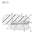
- Fig. 5 illustrates a stress curve 46 having a stress concentration portion 48 for the platform member 23 and bearing 20.
- Region 49 has a substantially uniform stress as represented by the horizontal line portion of curve 46 parallel to surface 32.
- the tapered surface T produces a maximum deformation ⁇ ' in the bearing 20 which deformation is not abrupt at the area adjacent the edge 34 as occurs in the prior art of Fig. 1. It should be understood that the drawing is not to scale and the actual inclination of tapered surface T is much less than that illustrated, which inclination is exaggerated for purposes of illustration.
- the deformation ⁇ ' is gradual and tapers slightly from essentially a minimum or negligible value at the edge 34 to the maximum value in the interior region 49 of platform 23 surface 32 and bearing 20 surface 28 a distance W (Fig. 8).
- the stress concentration in the region of curve portion 48 of curve 46 is a maximum of about 25% greater than the average value of the stress in the remaining portion of curve 46.
- a preferred embodiment of prothesis component platform 72 is shown in stress contact with a thermoplastic bearing 74.
- the stress contour is shown by curve 76 having a stress concentration curve portion 78 in region 80.
- the tapered surface T' merges with the platform 72 planar surface 82 in a radius R n .
- the surface T' comprises a curvature of a series of contiguous tangentially coupled radii R 0 to R n as represented by dashed line 88.
- the surface T' blends in with the plane of surface 82 by radius R n but merges in a relatively sharp corner 90 with edge 84.
- the corner 90 is broken to remove burrs and to round it somewhat to remove the sharpness thereof in the interest of safety to persons handling the platform 72. Otherwise for purposes of minimizing edge wiping damage, the corner 90 need not have a radius, including the relatively small radius R s of Fig. 8.
- the relatively small radius R s is not needed because the compressive stress curve portion 78 is reduced in value without that radius. No edge radius on the platform at corner 90 is therefore necessary to minimize the wear at the platform edge 84.
- the stress concentration at the edge region 80 is reduced as manifested by the gradual change in deformation ⁇ '' in region 80 from the bearing surface 92, not in contact with platform surface T', to interior bearing surface 94 in contact with surface 82.
- the stress concentration in region 80 thus increases prefereably in this embodiment a maximum of only about 25% as illustrated. This is a significant reduction in stress in the bearing 20 as compared to a 400% edge stress concentration of the prior art bearing arrangement of Fig. 1. While a 25% increase in stress concentration is illustrated in the present embodiment, other values, e.g., up to about 100% increase may be permissible in certain implementations. Since the taper of tapered surface T may be controlled to predetermined requirements, the 25% or even less increase in stress concentration is not a problem to achieve, and the lower the value the better the bearing edge wear performance of a given implementation.
- a similar edge wiping configuration is associated with the patellar bearing 48 and patellar platform 50 of the patellar component 18, Fig. 2.
- the patellar platform 50 surface edge 52 is also tapered with a tapered surface T similar to the tapering of the platform member 23 of Fig. 5.
- the edge tapering described has another benefit.
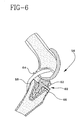
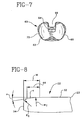
- the embodiment of the tibial bearing 20 of Figs. 3 and 4 is intended for use in a knee replacement where the posterior cruciate ligament of the knee 54, Fig. 2, is not retained. Where the posterior cruciate ligament 58 is retained in a knee 56, Fig. 6, an alternate embodiment knee replacement 60, shown in Figs. 6 and 7, is used.
- a posterior cruciate retaining tibial bearing 62 has a posterior bearing notch 64 to clear the ligament 58.
- the associated tibial platform 66 has a posterior platform notch 68, Fig. 7, to accommodate the ligament 58.
- a tapered edge 70 on the platform 66 allows the use of a common tibial platform for both bearing types of Figs. 2-4, bearing 20 and Figs. 6 and 7, bearing 62 (the latter with a notch 64) substantially reducing the amount and thus cost of inventory associated with a system for knee replacement. Further, the use of a common tibial platform 66, Figs. 6 and 7, eliminates the possibility of the wrong platform being use with a particular bearing.
- the tapered region 44 is a cylindrical surface (where the edge 34 is straight) or a toroidal surface (where the edge 34 is an arc) of width W, where the preferred taper radius R t of the cross section of the cylinder or toroid is very large compared to the normally used small radius R s at the platform corner.
- Finite element analysis of the tapered edge configuration and the prior art edge 42 of Fig. 1 shows a stress magnification of only about 25% for the tapered edge but an almost 400% stress magnification for the prior art edge 42 as discussed above. In most prothesis designs using articulating bearing and platform surfaces, the peak bearing pressures do not occur at the edge, thus a minor stress increase does not substantially increase overall surface damage. However, a four times increase in stress at the edge will, in most implementations, mean that the stresses at the edge significantly exceed those away from the edge and thus such a magnification will substantially increase overall surface damage.
- the use of a prothesis according to the present invention can in most instances substantially eliminate the adverse effect of stress edge wiping allowing the development and use of improved designs of improved performance and an increased range of application.
- the present invention has wide applicability to the prosthetic art and can be applied to almost all replacement joints now in use including hips, ankles, shoulders, fingers, toes, and elbow.
Landscapes
- Health & Medical Sciences (AREA)
- Orthopedic Medicine & Surgery (AREA)
- Heart & Thoracic Surgery (AREA)
- Vascular Medicine (AREA)
- Oral & Maxillofacial Surgery (AREA)
- Transplantation (AREA)
- Engineering & Computer Science (AREA)
- Biomedical Technology (AREA)
- Veterinary Medicine (AREA)
- Cardiology (AREA)
- Life Sciences & Earth Sciences (AREA)
- Animal Behavior & Ethology (AREA)
- General Health & Medical Sciences (AREA)
- Public Health (AREA)
- Physical Education & Sports Medicine (AREA)
- Prostheses (AREA)
Applications Claiming Priority (2)
| Application Number | Priority Date | Filing Date | Title |
|---|---|---|---|
| US08/345,302 US5683467A (en) | 1994-11-28 | 1994-11-28 | Prosthesis with articulating surface stress reducing contact edge |
| US345302 | 1994-11-28 |
Publications (3)
| Publication Number | Publication Date |
|---|---|
| EP0716838A2 EP0716838A2 (en) | 1996-06-19 |
| EP0716838A3 EP0716838A3 (ja) | 1996-06-26 |
| EP0716838B1 true EP0716838B1 (en) | 2000-02-02 |
Family
ID=23354466
Family Applications (1)
| Application Number | Title | Priority Date | Filing Date |
|---|---|---|---|
| EP95118660A Expired - Lifetime EP0716838B1 (en) | 1994-11-28 | 1995-11-27 | Prosthesis with articulating surface stress reducing contact edge |
Country Status (12)
| Country | Link |
|---|---|
| US (2) | US5683467A (ja) |
| EP (1) | EP0716838B1 (ja) |
| JP (1) | JP3504047B2 (ja) |
| KR (1) | KR100375563B1 (ja) |
| AR (1) | AR000216A1 (ja) |
| AT (1) | ATE189376T1 (ja) |
| AU (1) | AU694578B2 (ja) |
| BR (1) | BR9505314A (ja) |
| CA (1) | CA2163725C (ja) |
| DE (1) | DE69514899T2 (ja) |
| NO (1) | NO954817D0 (ja) |
| NZ (1) | NZ280553A (ja) |
Families Citing this family (42)
| Publication number | Priority date | Publication date | Assignee | Title |
|---|---|---|---|---|
| US6290726B1 (en) | 2000-01-30 | 2001-09-18 | Diamicron, Inc. | Prosthetic hip joint having sintered polycrystalline diamond compact articulation surfaces |
| US6494918B1 (en) | 2000-01-30 | 2002-12-17 | Diamicron, Inc. | Component for a prosthetic joint having a diamond load bearing and articulation surface |
| US6676704B1 (en) | 1994-08-12 | 2004-01-13 | Diamicron, Inc. | Prosthetic joint component having at least one sintered polycrystalline diamond compact articulation surface and substrate surface topographical features in said polycrystalline diamond compact |
| US6402787B1 (en) | 2000-01-30 | 2002-06-11 | Bill J. Pope | Prosthetic hip joint having at least one sintered polycrystalline diamond compact articulation surface and substrate surface topographical features in said polycrystalline diamond compact |
| US6425922B1 (en) | 2000-01-30 | 2002-07-30 | Diamicron, Inc. | Prosthetic hip joint having at least one sintered polycrystalline diamond compact articulation surface |
| US6793681B1 (en) | 1994-08-12 | 2004-09-21 | Diamicron, Inc. | Prosthetic hip joint having a polycrystalline diamond articulation surface and a plurality of substrate layers |
| US6596225B1 (en) | 2000-01-31 | 2003-07-22 | Diamicron, Inc. | Methods for manufacturing a diamond prosthetic joint component |
| US6514289B1 (en) | 2000-01-30 | 2003-02-04 | Diamicron, Inc. | Diamond articulation surface for use in a prosthetic joint |
| US5683467A (en) * | 1994-11-28 | 1997-11-04 | Biomedical Engineering Trust I | Prosthesis with articulating surface stress reducing contact edge |
| US6090144A (en) | 1998-05-12 | 2000-07-18 | Letot; Patrick | Synthetic knee system |
| US6443991B1 (en) | 1998-09-21 | 2002-09-03 | Depuy Orthopaedics, Inc. | Posterior stabilized mobile bearing knee |
| AU771796B2 (en) * | 1999-02-03 | 2004-04-01 | Depuy Orthopaedics, Inc. | Modular joint prosthesis system |
| US6165223A (en) * | 1999-03-01 | 2000-12-26 | Biomet, Inc. | Floating bearing knee joint prosthesis with a fixed tibial post |
| US6413279B1 (en) | 1999-03-01 | 2002-07-02 | Biomet, Inc. | Floating bearing knee joint prosthesis with a fixed tibial post |
| IT1310371B1 (it) * | 1999-05-13 | 2002-02-13 | Ist Ortopedici Rizzoli | Dispositivo di protesi per articolazione umana, in particolare perarticolazione della tibotarsica e relativo metodo di impianto. |
| US6410877B1 (en) | 2000-01-30 | 2002-06-25 | Diamicron, Inc. | Methods for shaping and finishing prosthetic joint components including polycrystalline diamond compacts |
| US6709463B1 (en) | 2000-01-30 | 2004-03-23 | Diamicron, Inc. | Prosthetic joint component having at least one solid polycrystalline diamond component |
| US6503280B2 (en) | 2000-12-26 | 2003-01-07 | John A. Repicci | Prosthetic knee and method of inserting |
| US20040162619A1 (en) | 2001-08-27 | 2004-08-19 | Zimmer Technology, Inc. | Tibial augments for use with knee joint prostheses, method of implanting the tibial augment, and associated tools |
| US7892288B2 (en) | 2001-08-27 | 2011-02-22 | Zimmer Technology, Inc. | Femoral augments for use with knee joint prosthesis |
| US20030065397A1 (en) | 2001-08-27 | 2003-04-03 | Hanssen Arlen D. | Prosthetic implant support structure |
| ATE457707T1 (de) | 2001-12-04 | 2010-03-15 | Active Implants Corp | Kissenlagerungsimplantate für lasttragende anwendungen |
| WO2003099156A2 (en) | 2002-05-23 | 2003-12-04 | Discure, Ltd. | Joint and dental implants |
| USD684693S1 (en) | 2002-08-22 | 2013-06-18 | Zimmer, Inc. | Prosthetic implant support structure |
| EP1477142A3 (de) * | 2003-05-13 | 2005-01-05 | Privelop AG | Kniegelenkendoprothese |
| US7175666B2 (en) * | 2004-04-30 | 2007-02-13 | Zimmer Technology, Inc. | Modular implant with a micro-motion damper |
| US8308812B2 (en) | 2006-11-07 | 2012-11-13 | Biomedflex, Llc | Prosthetic joint assembly and joint member therefor |
| US8070823B2 (en) * | 2006-11-07 | 2011-12-06 | Biomedflex Llc | Prosthetic ball-and-socket joint |
| US20110166671A1 (en) * | 2006-11-07 | 2011-07-07 | Kellar Franz W | Prosthetic joint |
| US8512413B2 (en) | 2006-11-07 | 2013-08-20 | Biomedflex, Llc | Prosthetic knee joint |
| US8029574B2 (en) * | 2006-11-07 | 2011-10-04 | Biomedflex Llc | Prosthetic knee joint |
| US9005306B2 (en) * | 2006-11-07 | 2015-04-14 | Biomedflex, Llc | Medical Implants With Compliant Wear-Resistant Surfaces |
| US9005307B2 (en) | 2006-11-07 | 2015-04-14 | Biomedflex, Llc | Prosthetic ball-and-socket joint |
| JP5663118B2 (ja) * | 2008-02-18 | 2015-02-04 | マックス オーソピディックス、インク. | 高次nurbs曲面を有する全置換人工膝関節 |
| DK2130518T3 (da) | 2008-06-03 | 2013-07-29 | Depuy Products Inc | Porøse femorale titanbøsninger |
| ES2455090T3 (es) * | 2008-06-03 | 2014-04-14 | Depuy (Ireland) | Manguitos tibiales porosos en titanio |
| WO2009158318A1 (en) | 2008-06-27 | 2009-12-30 | Zimmer, Inc. | Acl accommodating tibial design |
| US8308808B2 (en) | 2010-02-19 | 2012-11-13 | Biomet Manufacturing Corp. | Latent mobile bearing for prosthetic device |
| EP2712308B1 (en) | 2011-05-20 | 2016-01-13 | Zimmer, Inc. | Stabilizing prosthesis support structure |
| WO2014080416A1 (en) | 2012-11-21 | 2014-05-30 | Mehta Krishnachandra Chandrashanker | Knee replacement prosthetic |
| US9757243B2 (en) | 2014-07-08 | 2017-09-12 | Zimmer, Inc. | Intercondylar component and fin attachment features for use in knee arthroplasty |
| JP6916290B2 (ja) | 2017-01-20 | 2021-08-11 | バイオメット マニュファクチャリング,リミティド ライアビリティ カンパニー | モジュール式増強コンポーネント |
Family Cites Families (18)
| Publication number | Priority date | Publication date | Assignee | Title |
|---|---|---|---|---|
| US3715763A (en) * | 1971-04-21 | 1973-02-13 | W Link | Artificial limb for the knee joint |
| US4081866A (en) * | 1977-02-02 | 1978-04-04 | Howmedica, Inc. | Total anatomical knee prosthesis |
| CH615585A5 (ja) * | 1977-06-22 | 1980-02-15 | Sulzer Ag | |
| US4470158A (en) * | 1978-03-10 | 1984-09-11 | Biomedical Engineering Corp. | Joint endoprosthesis |
| JPS6077752A (ja) * | 1983-09-30 | 1985-05-02 | 東海林 宏 | メニスカル人工膝関節 |
| CH667988A5 (de) * | 1985-11-18 | 1988-11-30 | Sulzer Ag | Kuenstliche hueftgelenkspfanne. |
| AT386948B (de) * | 1987-07-09 | 1988-11-10 | Menschik Alfred Dr | Kuenstliches hueftgelenk |
| FR2634373B1 (fr) * | 1988-07-25 | 1990-10-26 | Lebeguec Pierre | Prothese totale du genou |
| US4917530A (en) * | 1989-08-31 | 1990-04-17 | Boehringer Mannheim Corporation | Structural joint |
| US5021061A (en) * | 1990-09-26 | 1991-06-04 | Queen's University At Kingston | Prosthetic patello-femoral joint |
| WO1992008424A1 (en) * | 1990-11-14 | 1992-05-29 | Arch Development Corporation | Improved floating bearing prosthetic knee |
| US5395401A (en) * | 1991-06-17 | 1995-03-07 | Bahler; Andre | Prosthetic device for a complex joint |
| DE9110504U1 (de) * | 1991-08-24 | 1991-10-31 | Aesculap AG, 7200 Tuttlingen | Kniegelenkendoprothese |
| US5152799A (en) * | 1991-10-04 | 1992-10-06 | Exactech, Inc. | Prosthetic femoral stem |
| FR2698537B1 (fr) * | 1992-12-01 | 1995-01-06 | Medinov Sa | Prothèse tricompartimentale du genou. |
| US5358530A (en) * | 1993-03-29 | 1994-10-25 | Zimmer, Inc. | Mobile bearing knee |
| US5489311A (en) * | 1994-01-21 | 1996-02-06 | Joint Medical Products Corporation | Prosthesis with orientable bearing surface |
| US5683467A (en) * | 1994-11-28 | 1997-11-04 | Biomedical Engineering Trust I | Prosthesis with articulating surface stress reducing contact edge |
-
1994
- 1994-11-28 US US08/345,302 patent/US5683467A/en not_active Expired - Lifetime
-
1995
- 1995-11-22 KR KR1019950043025A patent/KR100375563B1/ko not_active IP Right Cessation
- 1995-11-24 AU AU39066/95A patent/AU694578B2/en not_active Ceased
- 1995-11-24 CA CA002163725A patent/CA2163725C/en not_active Expired - Fee Related
- 1995-11-27 AT AT95118660T patent/ATE189376T1/de active
- 1995-11-27 NO NO954817A patent/NO954817D0/no unknown
- 1995-11-27 EP EP95118660A patent/EP0716838B1/en not_active Expired - Lifetime
- 1995-11-27 DE DE69514899T patent/DE69514899T2/de not_active Expired - Lifetime
- 1995-11-28 JP JP33274995A patent/JP3504047B2/ja not_active Expired - Fee Related
- 1995-11-28 NZ NZ280553A patent/NZ280553A/en not_active IP Right Cessation
- 1995-11-28 BR BR9505314A patent/BR9505314A/pt not_active IP Right Cessation
- 1995-11-28 AR AR33441095A patent/AR000216A1/es unknown
-
1997
- 1997-08-19 US US08/914,126 patent/US5824101A/en not_active Expired - Lifetime
Also Published As
| Publication number | Publication date |
|---|---|
| AU3906695A (en) | 1996-06-06 |
| JP3504047B2 (ja) | 2004-03-08 |
| EP0716838A2 (en) | 1996-06-19 |
| EP0716838A3 (ja) | 1996-06-26 |
| DE69514899T2 (de) | 2000-10-05 |
| CA2163725C (en) | 2000-01-18 |
| KR100375563B1 (ko) | 2003-12-31 |
| NZ280553A (en) | 1997-06-24 |
| CA2163725A1 (en) | 1996-05-29 |
| ATE189376T1 (de) | 2000-02-15 |
| JPH08224262A (ja) | 1996-09-03 |
| US5683467A (en) | 1997-11-04 |
| AR000216A1 (es) | 1997-05-21 |
| BR9505314A (pt) | 1997-10-21 |
| KR960016853A (ko) | 1996-06-17 |
| AU694578B2 (en) | 1998-07-23 |
| NO954817D0 (no) | 1995-11-27 |
| US5824101A (en) | 1998-10-20 |
| DE69514899D1 (de) | 2000-03-09 |
Similar Documents
| Publication | Publication Date | Title |
|---|---|---|
| EP0716838B1 (en) | Prosthesis with articulating surface stress reducing contact edge | |
| US10849760B2 (en) | Orthopaedic knee prosthesis having controlled condylar curvature | |
| US7025789B2 (en) | Prosthetic device and method for total joint replacement in small joint arthroplasty | |
| EP0765645B1 (en) | Femoral component condyle design for knee prosthesis | |
| EP0850608B1 (en) | Modular joint prosthesis augmentation system | |
| US5928285A (en) | Orthopaedic implant having an articulating surface with a conforming and translational surface | |
| EP1064889B1 (en) | Tibial knee component with a mobile bearing | |
| EP0746274B1 (en) | Joint endoprosthesis | |
| EP1337204B1 (en) | An orthopaedic joint prosthesis | |
| US9168145B2 (en) | Posterior stabilized orthopaedic knee prosthesis having controlled condylar curvature | |
| US20070173944A1 (en) | Endoprosthesis with intermediate part | |
| JPH08508190A (ja) | 移植自在の補てつ膝蓋骨要素 | |
| AU2002220859A1 (en) | An orthopaedic joint prosthesis | |
| EP1713420A2 (en) | Femoral implant for hip arthroplasty | |
| GB2381458A (en) | An osteoprosthesis component |
Legal Events
| Date | Code | Title | Description |
|---|---|---|---|
| PUAI | Public reference made under article 153(3) epc to a published international application that has entered the european phase |
Free format text: ORIGINAL CODE: 0009012 |
|
| PUAL | Search report despatched |
Free format text: ORIGINAL CODE: 0009013 |
|
| AK | Designated contracting states |
Kind code of ref document: A2 Designated state(s): AT BE CH DE DK ES FR GB GR IE IT LI LU MC NL PT SE |
|
| AK | Designated contracting states |
Kind code of ref document: A3 Designated state(s): AT BE CH DE DK ES FR GB GR IE IT LI LU MC NL PT SE |
|
| 17P | Request for examination filed |
Effective date: 19961127 |
|
| 17Q | First examination report despatched |
Effective date: 19981015 |
|
| GRAG | Despatch of communication of intention to grant |
Free format text: ORIGINAL CODE: EPIDOS AGRA |
|
| GRAG | Despatch of communication of intention to grant |
Free format text: ORIGINAL CODE: EPIDOS AGRA |
|
| GRAH | Despatch of communication of intention to grant a patent |
Free format text: ORIGINAL CODE: EPIDOS IGRA |
|
| GRAH | Despatch of communication of intention to grant a patent |
Free format text: ORIGINAL CODE: EPIDOS IGRA |
|
| GRAA | (expected) grant |
Free format text: ORIGINAL CODE: 0009210 |
|
| AK | Designated contracting states |
Kind code of ref document: B1 Designated state(s): AT BE CH DE DK ES FR GB GR IE IT LI LU MC NL PT SE |
|
| PG25 | Lapsed in a contracting state [announced via postgrant information from national office to epo] |
Ref country code: NL Free format text: LAPSE BECAUSE OF FAILURE TO SUBMIT A TRANSLATION OF THE DESCRIPTION OR TO PAY THE FEE WITHIN THE PRESCRIBED TIME-LIMIT Effective date: 20000202 Ref country code: LI Free format text: LAPSE BECAUSE OF FAILURE TO SUBMIT A TRANSLATION OF THE DESCRIPTION OR TO PAY THE FEE WITHIN THE PRESCRIBED TIME-LIMIT Effective date: 20000202 Ref country code: GR Free format text: LAPSE BECAUSE OF NON-PAYMENT OF DUE FEES Effective date: 20000202 Ref country code: ES Free format text: THE PATENT HAS BEEN ANNULLED BY A DECISION OF A NATIONAL AUTHORITY Effective date: 20000202 Ref country code: CH Free format text: LAPSE BECAUSE OF FAILURE TO SUBMIT A TRANSLATION OF THE DESCRIPTION OR TO PAY THE FEE WITHIN THE PRESCRIBED TIME-LIMIT Effective date: 20000202 Ref country code: BE Free format text: LAPSE BECAUSE OF FAILURE TO SUBMIT A TRANSLATION OF THE DESCRIPTION OR TO PAY THE FEE WITHIN THE PRESCRIBED TIME-LIMIT Effective date: 20000202 Ref country code: AT Free format text: LAPSE BECAUSE OF FAILURE TO SUBMIT A TRANSLATION OF THE DESCRIPTION OR TO PAY THE FEE WITHIN THE PRESCRIBED TIME-LIMIT Effective date: 20000202 |
|
| REF | Corresponds to: |
Ref document number: 189376 Country of ref document: AT Date of ref document: 20000215 Kind code of ref document: T |
|
| REG | Reference to a national code |
Ref country code: CH Ref legal event code: EP |
|
| ET | Fr: translation filed | ||
| REF | Corresponds to: |
Ref document number: 69514899 Country of ref document: DE Date of ref document: 20000309 |
|
| ITF | It: translation for a ep patent filed | ||
| PG25 | Lapsed in a contracting state [announced via postgrant information from national office to epo] |
Ref country code: SE Free format text: LAPSE BECAUSE OF FAILURE TO SUBMIT A TRANSLATION OF THE DESCRIPTION OR TO PAY THE FEE WITHIN THE PRESCRIBED TIME-LIMIT Effective date: 20000502 Ref country code: PT Free format text: LAPSE BECAUSE OF FAILURE TO SUBMIT A TRANSLATION OF THE DESCRIPTION OR TO PAY THE FEE WITHIN THE PRESCRIBED TIME-LIMIT Effective date: 20000502 Ref country code: DK Free format text: LAPSE BECAUSE OF FAILURE TO SUBMIT A TRANSLATION OF THE DESCRIPTION OR TO PAY THE FEE WITHIN THE PRESCRIBED TIME-LIMIT Effective date: 20000502 |
|
| REG | Reference to a national code |
Ref country code: IE Ref legal event code: FG4D |
|
| NLV1 | Nl: lapsed or annulled due to failure to fulfill the requirements of art. 29p and 29m of the patents act | ||
| PG25 | Lapsed in a contracting state [announced via postgrant information from national office to epo] |
Ref country code: LU Free format text: LAPSE BECAUSE OF NON-PAYMENT OF DUE FEES Effective date: 20001127 |
|
| PG25 | Lapsed in a contracting state [announced via postgrant information from national office to epo] |
Ref country code: MC Free format text: THE PATENT HAS BEEN ANNULLED BY A DECISION OF A NATIONAL AUTHORITY Effective date: 20001130 |
|
| PLBE | No opposition filed within time limit |
Free format text: ORIGINAL CODE: 0009261 |
|
| STAA | Information on the status of an ep patent application or granted ep patent |
Free format text: STATUS: NO OPPOSITION FILED WITHIN TIME LIMIT |
|
| 26N | No opposition filed | ||
| REG | Reference to a national code |
Ref country code: GB Ref legal event code: IF02 |
|
| PGFP | Annual fee paid to national office [announced via postgrant information from national office to epo] |
Ref country code: IT Payment date: 20111228 Year of fee payment: 17 |
|
| PG25 | Lapsed in a contracting state [announced via postgrant information from national office to epo] |
Ref country code: IT Free format text: LAPSE BECAUSE OF NON-PAYMENT OF DUE FEES Effective date: 20121127 |
|
| PGFP | Annual fee paid to national office [announced via postgrant information from national office to epo] |
Ref country code: FR Payment date: 20141110 Year of fee payment: 20 Ref country code: GB Payment date: 20141126 Year of fee payment: 20 Ref country code: IE Payment date: 20141110 Year of fee payment: 20 Ref country code: DE Payment date: 20141118 Year of fee payment: 20 |
|
| REG | Reference to a national code |
Ref country code: DE Ref legal event code: R071 Ref document number: 69514899 Country of ref document: DE |
|
| REG | Reference to a national code |
Ref country code: GB Ref legal event code: PE20 Expiry date: 20151126 |
|
| REG | Reference to a national code |
Ref country code: IE Ref legal event code: MK9A |
|
| PG25 | Lapsed in a contracting state [announced via postgrant information from national office to epo] |
Ref country code: IE Free format text: LAPSE BECAUSE OF EXPIRATION OF PROTECTION Effective date: 20151127 Ref country code: GB Free format text: LAPSE BECAUSE OF EXPIRATION OF PROTECTION Effective date: 20151126 |