EP0716495A2 - Battery charger - Google Patents
Battery charger Download PDFInfo
- Publication number
- EP0716495A2 EP0716495A2 EP95119067A EP95119067A EP0716495A2 EP 0716495 A2 EP0716495 A2 EP 0716495A2 EP 95119067 A EP95119067 A EP 95119067A EP 95119067 A EP95119067 A EP 95119067A EP 0716495 A2 EP0716495 A2 EP 0716495A2
- Authority
- EP
- European Patent Office
- Prior art keywords
- case
- battery
- grounding
- bottom portion
- grounding member
- Prior art date
- Legal status (The legal status is an assumption and is not a legal conclusion. Google has not performed a legal analysis and makes no representation as to the accuracy of the status listed.)
- Granted
Links
Images


Classifications
-
- H—ELECTRICITY
- H02—GENERATION; CONVERSION OR DISTRIBUTION OF ELECTRIC POWER
- H02J—CIRCUIT ARRANGEMENTS OR SYSTEMS FOR SUPPLYING OR DISTRIBUTING ELECTRIC POWER; SYSTEMS FOR STORING ELECTRIC ENERGY
- H02J7/00—Circuit arrangements for charging or depolarising batteries or for supplying loads from batteries
- H02J7/0042—Circuit arrangements for charging or depolarising batteries or for supplying loads from batteries characterised by the mechanical construction
Definitions
- the present invention relates to a battery charger suitable for charging a battery of a motor-driven vehicle such as a bicycle provided with a motor Japanese Utility Model Laid-open No. Hei 4-131861 discloses a battery charger, in which water permeated in an insertion port for a charging terminal is discharged from the bottom of the case of the battery charger.
- a cylindrical portion with a bottom which has an opening portion at the upper end for insertion of a charging terminal, is provided in the case of the battery charger.
- a drain hole is provided in the bottom portion of the cylindrical portion.
- a funnel-shape drain cylinder is disposed under the bottom portion of the cylindrical portion, and the outer periphery of the bottom portion of the cylindrical portion is fitted in the upper end portion of the drain cylinder. The lower end portion of the drain cylinder is then connected to a drain port opened to the bottom portion of the case.
- an object of the present invention is to provide a battery charger having a structure capable of speedily discharging water in the state that the battery charger is grounded.
- Another object of the present invention is to provide a battery charger having a structure being difficult to be fallen.
- a further object of the present invention is to provide a battery charger having a structure in which water is difficult to permeate in the case of the battery charger through a mating portion-of the case or a grommet portion provided in a cord outlet, and further water permeated in the case therethrough is difficult to reach electric components in the case and also speedily discharged.
- a battery charger having a case and electric components packed in the case, the case comprising: an inner case for containing the electric components; an outer case for covering at least an opening portion of the inner case; and a grounding member for supporting the bottom portion of the inner case and serving as a grounding portion of the case; wherein the grounding member has a grounding width larger than the width of the bottom portion of the inner case; drain holes are provided on both the inner case and the grounding member; and the drain holes provided in the grounding member are positioned higher than a grounding surface of the grounding member.
- a positioning recess fittable to the bottom portion of a battery may be formed on the upper surface of the outer case for placing the battery on the outer case in such a manner as to be positioned by the positioning recess.
- the battery includes a single battery and a combined battery containing a plurality of unit cells.
- a battery charger of the present invention includes a case having an outer case, an inner case and a grounding member, wherein the grounding width of the grounding member for supporting the inner case is larger than the width of the bottom surface of the inner case; drain holes are provided on both the inner case and the grounding member; and the drain holes provided in the grounding member are positioned higher than the grounding surface of the grounding member.
- the drain holes of the grounding member are positioned higher than the grounding surface not to be blocked with the ground, water permeating in the case can be speedily discharged. Moreover, since the grounding width of the grounding member is larger than the bottom surface of the inner case, the battery charger is difficult to be fallen and it can be stably grounded.
- a positioning recess fittable to the bottom portion of a battery case is formed in the upper surface of an outer case of the battery charger, and accordingly, each unit cell in the battery case can be discharged' in the state that the battery case is placed on the outer case.
- the charging of the unit cell can be effected in a relatively small space, and further the battery case can be stably supported during charging.
- Fig. 1 is a side view of a bicycle provided with an auxiliary motive-power device used in the present invention.
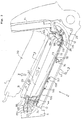
- Fig. 2 is a side view showing essential portions of the front frame portion of the bicycle shown in Fig. 1.
- Fig. 3 is a sectional view taken along the line 3-3 of Fig. 2.
- Fig. 4 is a sectional view of a battery case of the bicycle provided with an auxiliary motive-power device, with parts partially cut-away.
- Fig. 5 is a view showing a front-side mounting structure of the battery case.
- Fig. 6 is a view of a pop-up mechanism, as seen from the direction of the arrow Z of Fig. 2.
- Fig. 7 is an enlarged view of essential portions of a rear-side mounting structure of the battery case.
- Fig. 8 is a view showing the entire configuration of an embodiment of a battery charger of the present invention.
- Fig. 9 is a plan view of a main body of the battery charger shown in Fig. 8.
- Fig. 10 is a bottom view of the battery charger shown in Fig. 8.
- Fig. 11 is an enlarged view of a grommet mounting portion of the battery charger shown in Fig. 8.
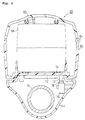
- Fig. 12 is a sectional view taken along the line 12-12 of Fig. 9.
- Fig. 13 is a side view showing the outline of another embodiment of the battery discharger of the present invention.
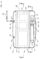
- Fig. 14 is a plan view of the battery discharger shown Fig. 13.
- Fig. 15 is a sectional view taken along the line 15-15 of Fig. 13.
- Fig. 16 is a sectional view taken along the line 16-16 of Fig. 14.
- Fig. 17 is a sectional view taken along the line 17-17 of Fig. 14.
- Fig. 18 is a bottom view of the battery discharger shown in Fig. 13.
- Fig. 19 is a block diagram of a circuit contained in the battery charger shown in Fig. 13.
- Figs. 1 to 7 show a bicycle provided with an auxiliary motive-power device including a battery case chargeable by a battery charger of the present invention.
- Fig. 1 is a side view of the entire configuration of the bicycle.
- the bicycle includes a front frame 6 which is formed in a V-shape as seen from the side and disposed between a front wheel 2 and a rear wheel 4.
- the front frame 6 has a main frame 10 extending obliquely, downward, and backward from a head pipe 8; an intermediate portion 12 curved downward; and a seat frame 14 extending approximately in the vertical direction.
- the head pipe 8 turnably supports a front fork 16 for supporting at its lower end the front wheel 2, and a steering post 19 mounting at the upper end a handle 18.
- a battery case 20 for containing a battery (described later) is removably mounted between a front-side fixing portion 22 and a motor-side connector 26 functioning as a male connector.
- the battery case 20 has a length being approximately the same as that of the main frame 10.
- reference numeral 24 designates a lock device.
- the intermediate portion 12 supports an auxiliary motive-power generating device 30 through a hanger plate 28.
- a rear fork 32 with the front end mounted to the auxiliary motive-power generating device 30, extends approximately in the horizontal direction.
- the rear end of the rear fork 32 is connected to a bracket 36, together with the rear ends of a pair of right and left rear stays 34 extending obliquely and downward from the upper end of the seat frame 14, to form a rear frame 37.
- the bracket 36 rotatably supports a rear axle 5 of the rear wheel 4 and a driven sprocket 38.
- a saddle seat 42 is supported on the upper end portion of the seat frame 14 through a seat post 40.
- the surroundings of the front frame 6 and the auxiliary motive-power generating device 30 are covered with a body cover 44.
- the body cover 44 is divided into right and left parts.
- the front portion of the body cover 44 covers the front-side fixing portion 22, and is continuous to an inclined wall 45.
- An inclined wall 46 is formed, on the center portion of the body cover 44 which covers the lock device, in such a manner as to be inclined obliquely, backward, and upward.
- a front portion of the seat frame 14 has an opening portion which is blocked by a front panel 48.
- the auxiliary motive-power generating device 30 includes a control unit 50, a motor 52 and a transmission 54.
- a crank shaft 56, an output shaft of the transmission 54 is rotated integrally with a drive sprocket 58 for rotating the driven sprocket 38 of the rear wheel 4 through a chain 59.
- Pedals 57 are mounted on the crank shaft 56, which are stepped on to be manually driven. At this time, the motor 52 is rotated by an electric-power supplied from a battery in the battery case 20, to generate an auxiliary motive-power.
- the control unit 50 controls rotation of the motor 52 on the basis of a torque transmitted from the pedals 57 and the rotational frequency of the drive sprocket 58.
- Fig. 2 is a side view of the front frame 6 portion in the state that the body cover 44 is removed;
- Fig. 3 is a sectional view taken along the line 3-3 of Fig. 2;
- Fig. 4 is a side view of the battery case 20, with parts partially cut-away;
- Fig. 5 is a view showing a structure of mounting the front side of the battery case 20;
- Fig. 6 is a view showing essential portions of the structure shown in Fig. 5, as seen from the bottom (in the direction of the arrow Z of Fig. 1);
- Fig. 7 is a view showing a structure of mounting the rear side of the battery case 20.
- the front-side fixing portion 22 is provided on the front end portion of the main frame 10, and the motor-side connector 26 is provided in the vicinity of the intermediate portion 12.
- the battery case 20 can be shifted between a mounting position shown by the solid line A, and a pop-up position shown by the virtual line B.
- the front end portion of the battery case 20 is locked by the lock device 24 in the state that the rear end portion thereof is fitted to the motor-side connector 26.
- the pop-up position the front end portion of the battery case 20 is lifted after being released in locking.
- the battery case 20 is removed in the direction approximately perpendicular to the longitudinal direction of the main frame 10 (in the direction shown by the arrow X).
- the position shown by the virtual line C also shows the state before the battery case 20 is mounted.
- the battery case 20 can be slid approximately along the longitudinal direction of the main frame 10 (in the direction shown by the arrow Y).
- the battery case 20 is a plastic member vertically divided into an upper case 60 and a lower case 62.
- Mating faces 64, 64 of both the cases 60 and 62 are each stepped, and are overlapped at the stepped portions, to form a labyrinth structure for preventing permeation of water.
- a battery pack 66 is contained in the battery case 20.
- the upper portion of the battery pack 66 abuts rubber made grooved members 70 mounted on ribs 68 projecting downward from the inner surface of the upper case 60.
- the lower portion of the battery pack 66 abuts rubber made flat cushions 74 interposed between the bottom of the battery pack 66 and the bottom 72 of the lower case 62.
- the battery pack 66 is thus supported in the battery case 20 in such a manner as to be isolated from vibration.
- reference numeral 76 designates a limit switch which is mounted on the inner surface of the body cover 44.
- a projection 73 projecting downward from the bottom 72 of the lower case 62 pushes down a downward extending plate spring 78.
- the limit switch 76 is turned on.
- the limit switch 76 is turned off when the battery case 20 is located at the pop-up position (described later).
- the upper and lower cases 60, 62 of the battery case 20 are engaged with each other by means of an engagement claw 80 projecting upward from the lower case 62 on the first half of the side surface of the battery case 20, and are fastened to each other by a tapping screw 82 on the second half of the side surface of the battery case 20.
- the upper and lower cases 60, 62 are separably integrated with each other.
- a rubber cushion member 84 is interposed between the first half of the bottom of the lower case 62 and the main frame 10 side.
- a handle 86 is turnably mounted on the front end portion of the battery case 20.
- An inclined stepped portion 88 is stepped from a front surface 90 of the battery case 20 into a shape corresponding to that of the inclined wall 45 provided at the front end portion of the body cover 44 for covering the front side fixing portion 22 (see Fig. 1).
- a pressing stepped portion 92 is formed in the lower portion of the front surface 90 in such a manner as to cut into the front surface 90.
- a rear inclined surface 94 is formed on the rear end portion of the battery case 20 in such a manner as to be inclined obliquely, backward, and upward.
- the rear inclined surface 94 has a shape corresponding to that of the inclined wall 46 provided on the front end portion of the body cover 44 (see Fig. 1).
- a rear surface 96 of the upper case 60 is inclined in a shape having an inverse slope to that of the rear inclined surface 94.
- a battery-side connector 100 functioning as a female connector is mounted on the rear end portion of the battery case 20 by means of a vis 98 or the like.
- a rear surface 102 of the battery-side connector 100 forms a butt surface against the motor-side connector (described later).
- a positioning engagement projection 104 which is formed approximately into a triangular shape as seen from the side, projects from the center of the butt surface of the battery-side connector 100.
- the rear end of the bottom of the battery-side connector 100 forms a guide inclined surface 106 inclined backward and upward.
- the battery pack 66 is composed of a combination battery which packs the surroundings of a plurality of unit cells 110 with a heat-contractive tube 111.
- the unit cells 110 are arranged in such a manner that two sets of unit cells each connected in series are stacked in the vertical direction.
- the unit cell 110 is of a charging type, for example, a Ni-Cd type.
- the adjacent unit cells 110 are connected in series through each conducting plate 112, and are connected to a discharge terminal (described later) of the battery-side connector 100 through a fuse 114.
- reference numeral 116 designates a temperature detecting thermistor; 117 is a lead wire of the thermistor; and 118 is a charge terminal.
- the charge terminal 118 contains a reverse-current preventing diode, and is mounted on the rear surface of the lower case 62. Since being provided separately from the discharge terminal, the charge terminal 118 enables the battery to be charged even when the battery case 20 is mounted or when it is removed.
- Fig. 5 shows a detailed structure of the front-side fixing portion 22 for fixing the battery case 20.
- the front-side fixing portion 22 includes the lock device 24 and a pop-up mechanism.
- the lock device 24 is mounted on a vertically extending upright wall 122 of a front bracket 120 approximately L-shaped in section.
- the front bracket 120 is provided between the head pipe 8 and the front end portion of the main frame 10.
- the lock device 24 has a combination switch function of turning on/off a power source using a key 124 (see Fig. 6) and of locking/unlocking the battery case 20 by inserting a lock pin 126 in a lock hole 128 formed in the front surface 90.
- the key-position of the lock device 24 is as follows. At the on-position, the lock pin 126 is in the locking state, and the key 124 cannot be removed and a current is carried from the battery pack 66 to the motor 52. On the other hand, at the off-position, a current-carrying is stopped and the key 124 can be removed, but the lock pin 126 is left in the locking state. When the off-position is shifted to the lock position by pushing and turning the key 124, the lock pin 126 is released so that the battery case 20 can be removed.
- a lock plate 132 is mounted inside the front surface 90 by means of a vis 130 for reinforcing the front surface 90.
- An opening portion 134 corresponding to the lock hole 128 is formed in the lock plate 132.
- the lower end portion of the lock plate 132 extends up to the pressing stepped portion 92 and forms an exposed curved portion which constitutes longitudinal butt surface 136 to be butted upon unlocking and a butt surface 138 to be butted upon locking (see Fig. 5).
- the pop-up mechanism includes a pair of stays 140 provided on the upright wall 122 under the lock device 124; a rocking arm 144 supported by the stays 140 through a slide shaft 142; and tension springs 146 biasing the rocking arm 144 to turn it counterclockwise.
- the stays 140 projects forward while being spaced at an interval in the vehicular body width direction.
- a slot 148 extending longer in the longitudinal direction is formed in each of the stays 140 for allowing the slide shaft 142 to be movable in the longitudinal direction.
- the rocking arm 144 is approximately U-shaped, and a pair of right and left flat portions 150 of the rocking arm 144 are each overlapped on the outer surfaces of the stays 140.
- the slide shaft 142 extends to cross the right and left flat portions 150 through the slots 148 of the right and left stays 140, and is connected to the rocking arm 144 in such a manner that the rocking arm 144 is movable in the longitudinal direction relative to the stays 140 and is rockable around the slide shaft 142.
- a portion of the rocking arm 144 which extends in the vehicular body width direction and connects the right and left flat portions 150 to each other, forms a butting portion 152.
- the butting portion 152 is to be butted to the butt surface 136 (to be butted upon unlocking) or the butt surface 138 (to be butted upon locking) of the lock plate 132.
- the tension springs 146 are coil springs longitudinally extending along the right and left side surfaces of the main frame 10. With respect to the tension springs 146, front-side mounting portions 156 thereof are each locked with mounting projections 154 projecting from the front ends of the flat portions 150, and rear-side mounting portions 157 thereof are each locked with projections 158 projecting from the side surfaces of the main frame 10.
- the tension springs 146 usually bias the rocking arm 144 backward, and also bias the butting portion 152 to turn it counterclockwise. Accordingly, at the pop-up position shown by the virtual line B, the rocking arm 144 is drawn backward and the slide shaft 142 is moved to the rear ends of the slots 148, so that the butting portion 152 pushes up the butt surface 136 (to be butted upon unlocking). As a result, the tensile strength of the tension springs 146 almost acts as a pushing-up force F1.
- the butt surface 136 pushes down the butting portion 152 clockwise, and the rocking arm 144 is positioned to be approximately parallel to the length direction of the main frame 10.
- the butting portion 152 is pushed forward against the rocking arm 144 by the butt surface 138 (to be butted upon locking), and the slide shaft 142 is moved to the front ends of the slots 148.
- the butting portion 152 pushes the butt surface 136 (to be butted upon unlocking) and the butting surface 138 (to be butted upon locking).
- a force F2 applied by the butting portion 152 for pressing the butt surface 138 (to be butted upon locking) backward is very larger than a force F3 applied by the butting portion 152 for pushing up the butt surface 136 (to be butted upon unlocking).
- the pushing-up force F3 is sufficient to pop-up the front portion of the battery case 20 when the lock device 24 is released.
- the slide shaft 142 is moved to the rear ends of the slots 148, and the butting portion 152 is turned counterclockwise to push up the butt surface 136 (to be butted upon unlocking).
- reference numerals 121 and 159 designate indicators provided on the upper portion of the front bracket 120 for indicating the on-positions of the mounting stays 140 and the lock device 24 respectively.
- the motor-side connector 26 to be fitted to the battery-side connector 100 provided on the rear portion of the battery case 20 is provided near the intermediate portion of the main frame 10.
- an upper mounting portion 160 of the motor-side connector 26 is overlapped on a front center portion 49 of the lower end portion of the opening/closing portion 48 and mounted thereto by means of a vis 162 and a nut 164.
- the front center portion 49 has the same inclination as that of the rear surface 96, and upon mounting of the battery case 20, the front center portion 49 is matched to the rear surface 96 at the same inclination but with a slight gap.
- a lower mounting portion 166 of the motor-side connector 26 is mounted on the body cover 44 by means of a vis or the like (not shown).
- an abutment surface 170 is formed for positioning the longitudinal direction of the battery. Specifically, when the battery-side connector 100 is mounted, the rear surface 102 of the battery-side connector 100 abuts the abutment surface 170.
- a projection 172c projects backward from the position corresponding to the positioning engagement projection 104 of the battery-side connector 100.
- the projection 172c has on its inner side an engagement recess 172 for receiving the positioning engagement projection 104.
- a guide surface 174 having an inclination being approximately the same as that of the guide inclined surface 106 of the battery-side connector 100 is formed at the position corresponding the guide inclined surface 106.
- the engagement recess 172 is formed to be larger than the engagement projection 104.
- a top portion 104a of the engagement projection 104 abuts a top portion 172a of the engagement recess 172, so that the battery case 20 is positioned in the vertical direction.
- Lower-side inclined surfaces 172b and 104b of the engagement recess 172 and the engagement projections 104 are nearly equal to each other in inclination, and upon engagement, they are matched to each other nearly at the same inclination but with a slight gap.
- a pair of pin-like motor terminals 176 are provided on both sides of the abutment surface 170. Leading ends 178 of the motor terminals 176 project in the battery case 20. On the other hand, rear ends 180 of the motor terminals 176 exteriorly extend from the rear surface 168, and are connected to cords 182. The cords 182 are connected to the control unit 50.
- a pair of side wall portions 184 for receiving the batter-side connector 100 are formed on both sides of the motor-side connector 26. Front edge portions 186 of the side wall portions 184 are matched to the inclined walls 46 of the battery case 46 with a slight gap (see Fig. 2).
- an upper portion 190 of the battery-side connector 100 enters the upper case 60 and is positioned to the upper case 60 by means of projections 190a.
- Lower portions 192 of the battery-side connector 100 are mounted to the lower case 62 by means of vises 99 from the outside of the rear wall 63 (see Fig. 4) of the lower case 62.
- the rear-side center portion of the lower portion 192 forms a projecting portion 193 projecting outward and rearward from the center portion of the rear wall 93 (see Fig. 4).
- the rear surface 102 and the engagement projection 104 are formed, and further a pair of right and left terminal-passing holes 194 are formed at the positions corresponding to the motor terminals 176.
- the terminal-passing holes 194 are communicated to recesses 195 formed in the lower portion 192 on the lower case 62 side.
- the motor terminal 176 has a length allowing the leading end 178 thereof to project in the recess 195 through the terminal-passing hole 194 upon mounting of the battery case 20.
- a plate spring-like discharge terminal 196 is disposed in the recess 195 in such a manner as to extend longer in the vertical direction.
- the discharge terminal 190 is screwed with a nut 191 previously fixed on the upper portion 190, at an approximately U-shaped portion 197 formed at the upper end portion of the discharge terminal 196, to be thus electrically connected to the battery pack 66.
- a pair of the right and left recessed portions 195 are formed to put a bulkhead 199 therebetween so as to correspond to a pair of the right and left motor terminals 176.
- a vertical groove is formed in the bulkhead 199, and a guide projection 179 projecting for separating the right and left motor terminals 176 from each other is inserted in the groove.
- a free lower end 198 of the discharge terminal 196 is positioned to cover the exit, facing to the recess 195, of the terminal-passing hole 194, as shown by the virtual line in Fig. 7.
- the lower free end 198 is pushed forward and elastically deformed by the leading end 178 as shown by the solid line in Fig. 7.
- the lower free end 198 of the discharge terminal 196 is brought in contact with the leading end 178 of the motor terminal 176 at a high contact pressure.
- the limit switch 76 functions as follows: namely, at the pop-up position, the limit switch 76 is turned off for cutting off a current flowing from the lower free end 198 to the leading end 178, and only at the mounting position, the limit switch 76 is turned on for allowing a current to flow from the lower free end 198 to the leading end 178.
- the motor-side connector 26 is connected to or separated from the rear side of the battery case 20 by sliding the battery case 20 in the direction shown by the arrow Y in Fig. 2.
- the motor-terminals 176 are connected to or separated from the discharge terminals 196 of the battery-side connector 100, and at the same time the engagement projection 104 of the battery-side connector 100 is inserted in or separated from the engagement recess 172 of the motor-side connector 26.
- the stroke amount of the battery case 20 in the Y direction is determined by the stroke amount of the slide shaft 142.
- Figs. 8 to 12 are views each showing a separate type battery charger 200 to be connected to a charging terminal 118.
- Fig. 8 is a view showing the entire configuration of the battery charger 200 (a main body 202 of the battery charger 200 is shown in section taken along the line 8-8 of Fig. 9);
- Fig. 9 is a plan view of the main body 202;
- Fig. 10 is a bottom view of the main body 202;
- Fig. 11 is an enlarged sectional view of a grommet mounting portion;
- Fig. 12 is a sectional view taken along the line 12-12 of Fig. 9.
- the battery charger 200 includes the main body 202, a power supply plug 204 to be connected to a house-Service power supply (100 V), a coupler 206 to be connected to the charging terminal 118, a cord 208, and grommets 210, 212.
- a house-Service power supply 100 V
- a coupler 206 to be connected to the charging terminal 118
- a cord 208 a cord 208
- grommets 210, 212 grommets 210, 212.
- the main body 202 for containing electric components 218 such as an amplifier is vertically divided into an inner case 216 and an outer case 214.
- the main body 202 forms a case for the battery charger 200 in cooperation of a grounding member 220 for supporting the lower portion of the inner case 216.
- Bosses 222 are integrally formed on the outer case 214, and bosses 224 are integrally formed on the inner case 216. Bosses 226 are also integrally formed in the grounding member 220. The bosses 222, 224 and 226 are coaxially arranged, and are fastened from the bottom side by means of tapping screws 228.
- the outer case 214 is thus integrated with the inner case 216.
- case-side bottom drain holes 232 are formed in a bottom portion 230 of the inner case 216 in such a manner as to be spaced from each other at intervals in the longitudinal and lateral directions.
- a flange 234 is formed around each bottom drain hole 232.
- the grounding member 220 has a peripheral wall 238 formed with a fitting recess 236.
- the fitting recess 236 has a size being large enough for the inner case 216 to be freely fitted therein.
- a bottom portion 240 of the fitting recess 236 is slightly larger than the bottom portion 230 of the inner case 216.
- a pair of grounding member-side bottom drain holes 242 are formed in such a manner as to be spaced from each other at an interval in the lateral direction.
- the peripheral wall 238 is folded outward at the upper portion so as to form a double-wall shape, and the outer wall portion of the peripheral wall 238 spreads downward.
- the lower ends of four corner portions of the outer wall portion project downward from the bottom portion 240, to form grounding leg portions 244. With the grounding leg portions 244, the bottom portion 240 is, upon grounding, separated upward from the ground 246 by a height H.
- a slit S is formed between the upper edge of the peripheral wall 238 and the inner case 216. Also, recesses 248 for avoiding grommets 210, 212 are formed at the leading edge of the peripheral wall 238.
- Grounding member-side drain holes 250 are formed at four corners of the bottom portion 240. Such a hole is formed by slotting the peripheral wall 239 in the range from the bottom portion 240 side to the vicinity of the root of each grounding leg portion 244.
- inner walls 214b, 252 are integrally formed, respectively.
- the inner walls 214b, 252 are positioned near the grommet 210 in such a manner as to be approximately in parallel to the outer walls 214a, 216a, respectively.
- These outer walls 214a, 216a and the inner walls 214b, 252 form a grommet mounting portion.
- the grommet 210 has an outward extending portion 254, a large diameter portion 256, and an inward extending portion 258.
- the large diameter portion 256 is held between the outer walls 214a, 216a and the inner walls 214b, 252.
- the outward extending portion 254 is held between the outer walls 214a, 216a, and the inward extending portion 258 is held between the inner walls 214b, 252. With this arrangement, the outlet for the cord 208 is prevented from permeation of water.
- a drain portion 260 in the form of a downward open groove or hole is provided on the lower portion of the large diameter portion 256 in such a manner as to be communicated to a drain space 262 surrounded by the inner and outer walls 216a, 252 and the bottom portion 240.
- a communicating portion 266 is formed on the upper portion of the inner wall 252 at a position surrounding the inward extending portion 258 for communicating the drain space 262 to an electric component arranging space 264 positioned inside the inner walls 214b, 252.
- a grommet drain hole 268 is opened in the bottom 240 under the drain space 262. The position of the grommet drain hole 268 is shifted from that of the drain hole 250 in the lateral and longitudinal directions.
- drain hole 250 is shown in Fig. 8, 11 and 12, with the sectional position changed for surroundings. The same is true for the grounding member-side bottom drain hole 242 in Fig. 12.
- the grommet 212 has the same structure as that of the grommet 210, and therefore, the explanation thereof is omitted.
- the grommet mounting portion has a double wall structure by additionally providing the inner walls 214b, 252.
- the drain portion 260 is formed in the grommet 210 and the grommet-side drain hole 268 is formed in the bottom 240. Accordingly, even when water permeates in the case along the cord 208, the grommet 210 or the grommet 212, it is immediately discharged in the fitting recess 236 through the discharge space 262. As a result, it is difficult for water to permeate in the electric component arranging space 264 in which the electric components are arranged.
- case-side drain hole 232 is separated from the grounding member 220 at a sufficient interval for enabling water to be speedily discharged.
- Each interval between the grounding leg portions 244 of the grounding member 220 for supporting the case is larger than the width of the bottom portion 240 of the inner case 216. This is effective to prevent the falling of the battery charger 200 during use, and hence to stabilize the operation of the battery case 200.
- the case-side drain holes 232, 268 are respectively shifted in position from the grounding member-side drain holes 242, 250 for forming the labyrinth structure. Accordingly, even when the battery charger 200 is fallen, water permeating in the fitting recess 236 through the grounding member-side bottom drain holes 242 or 250 is difficult to further permeate in the electric component arranging space 264.
- the flange 234 is provided so as to surround the case-side bottom drain hole 232 and the grommet-side drain hole 268 is separated from the electric component arranging space 264 by means of the inner walls 214b, 252, so that the permeation of water in the electric component arranging space 264 can be further prevented.
- the objective battery can be suitably used for domestic electric components.
- Figs. 13 to 19 shows another embodiment of the battery charger of the present invention.
- Fig. 13 is a side view showing the entire configuration of the battery charger;
- Fig. 14 is a plan view of Fig. 13;
- Fig. 15 is a sectional view taken along the line 15-15 of Fig. 13;
- Fig. 16 is a sectional view taken along the line 16-16 of Fig. 14;
- Fig. 17 is a sectional view taken along the line 17-17 of Fig. 14;
- Fig. 18 is a bottom view of Fig. 13;
- Fig. 19 is a block diagram of a circuit contained in the battery charger.
- the case of the battery charger 300 includes an outer case 310 forming the upper portion and most of the side portion of the charger case, an inner case 320 contained inside the outer case 310, and a grounding member 330 for supporting the bottom of the inner case 320 (see Fig. 15).
- a positioning recess 311 extending in the longitudinal direction is formed at the center portion on the upper surface of the outer case 310.
- Parallel stepped portions 312 for fittably supporting the bottom portion of a battery case 360 are formed on both the sides of the positioning recess 311.
- the battery case 360 has a structure similar to that of the above-described battery case 20. As shown in Fig. 15, the bottom portion of the battery case 360 is fitted in the recess 311. At this time, projecting end portions 361 formed on both the sides of the bottom portion of the battery case 360 in such a manner as to put the positioning recess 311 therebetween are placed on the stepped portions 312. The battery case 360 is thus positioned so as to prevented from being shifted in the lateral direction.
- the center portion of the bottom of the battery case 360 forms a center recess 362 recessed upward.
- a thermal insulating space 363 is formed between the center recess 362 and the positioning recess 311. The space 363 has a gap enough to prevent heat from transmitting from the battery charger 300 side to the battery case 360.
- a pair of edge portions 310b extend along the stepped portions 312 in such a manner as to put the positioning recess 311 therebetween and raised from the positioning recess 311.
- Air discharge ports 313 are each formed in the edge portions 310b.
- a cord holder 314 for containing a coupler 301 and the cord 302 is recessed in one of the edge portions 310b in parallel to the stepped portion 312.
- On end of the cord holder 314 is continuous to a vertical hole 315 extending in the vertical direction, and the coil-shaped cord 302 extends in the battery charger 300 through this vertical hole 315.
- a charging lamp 316 for indicating the charging state by lighting is mounted in the vicinity of the vertical hole 315. Part of the charging lamp 316 exposed to the exterior (see Figs. 14, 17).
- a side surface 310c of the outer case 310 extends to the lower portion of the battery charger 300 for covering the battery charger 300.
- the end portion of the side surface 310c is connected to the upper end portion of a side wall 331 of the grounding member 330.
- a boss 317 and a rib 318 are integrally formed at each corner between an upper surface 310a and the side surface 310c in such a manner as to extend downward from the upper surface 310a.
- the boss 317 is connected to the upper end portion of the inner case 320 by means of a screw 321.
- the rib 318 is separated from the inside of the side surface 310c at an interval.
- the interval forms an air discharge space 319 which is connected to the air discharge port 313.
- the air discharge space 319 is also communicated to the interior of the inner case 320 through an air vent 322 formed in the upper end portion of the inner case 320.
- the inner case 320 is a vessel opened upward.
- a plurality of drain holes 323 are formed in the center of the bottom portion 320a in the lateral direction in such a manner as to be spaced from each other in the longitudinal direction at intervals (see Fig. 17).
- a boss 324 is formed at each corner of the bottom portion 320a.
- the bosses 324 are connected to the grounding member 330 by means of screws 325.
- Electric components 340 are contained in the inner case 320, and a circuit board 341 for the electric components 340 is mounted on the bosses 324 by means of screws 342.
- the center portion of the circuit board 341 is supported by a rib 326 projecting upward from the bottom portion 320a.
- a choke coil 343, a transformer 344 and a charge controlling unit 345 (see Figs. 16, 17) constituting part of the electric components 340 are mounted on the circuit board 341 by means of screws 347 (see Fig. 15).
- a thermal insulating member 346 is disposed on the back side of the positioning recess 311 over the electric components 340.
- holes 315a, 320c with grommets are formed at the lower wall of the vertical hole 315 and a connection portion between the upper end of the inner wall 320b of the inner case and the rib 310d near the vertical hole 315.
- the cord 302 is connected to the charge controlling unit 345 through these holes 315a, 320c.
- the vertical hole 315 vertically passes through the entire battery charger 300.
- the lower end portion of the vertical hole 315 is communicated to an opening portion 333 formed in the bottom portion of the grounding member 330. Water permeating in the inner case 320 can be discharged from the opening portion 333.
- a grounding member-side center drain hole 334 is formed so as to be shifted in position from the drain hole 323 of the bottom portion 320a of the inner case (see Fig. 17).
- a boss-like grounding leg 335 is formed at each corner of the bottom portion 332.
- a drain hole 336 is formed at the root of the grounding leg 335 which is separated upward from the ground.
- the circuit for the electric components 340 includes a constant current power supply 350 and the charge controlling unit 345.
- the constant current power supply 350 includes a rectifying portion 351 to be connected to a power supply plug 303, an FET 352, a CPU 353, and the transformer 344.
- the rectifying portion 351 has a smoothing capacitor 354 and the choke coil 343.
- a current rectified by the rectifying portion 351 flows to the transformer 344 through the FET 352 controlled by the CPU 353. A constant current is thus output from the transformer 344.
- the charge controlling portion 345 allows a current output from the transformer 344 to flow to the coupler 301 through a p-n-p type transistor 356 controlled to be turned on or off by the CPU 355.
- the emitter side is connected to the transformer 344; the base side is connected to the CPU 355; and the collector side is connected to the coupler 301 through the cord 302.
- the CPU 355 is connected to an intermediate portion between resistances R1, R2 connected between the transistor 356 and the coupler 301 by way of a monitor line 357 for monitoring a partial voltage of each unit cell (described later) contained in the battery case.
- the resistance R2 is grounded.
- the CPU 355 is also connected to a temperature detecting thermistor 364 provided in the battery case by way of a monitor line 358 for effecting on-off control of the transistor 356 on the basis of a temperature detected by the thermistor 364.
- Reference numeral 359 indicates the grounding side of the monitor line.
- a charging terminal 365 of the battery case 360 is connected to the positive electrode of a unit cell 366 contained in the battery pack through a counter-current preventive diode 356.
- the positive electrode of the unit cell 366 is connected to the battery-side connector through a fuse 368, while the negative electrode of the unit cell 366 is grounded through the charging terminal 365, the coupler 301 and the monitor line 359.
- the unit cell 366 contained in the battery case 360 is charged in the manner as shown in Figs. 13 and 15.
- the outer case 360 is longitudinally fitted in the fitting recess 311 formed in the outer case 310 of the battery charger 300.
- the projecting end portions 361 of the battery case 360 are placed on the stepped portions 312 of the outer case 310.
- the coupler 301 is pulled from the cord holder 314 and connected to the charging terminal 365.
- the power supply plug 303 is connected to the house-service power supply.
- the battery case 360 is left as being placed on the battery charger 300 during charging. As a result, the charging of the unit cell can be effected in a relatively small space. In addition, since the battery case 360 is fitted in the positioning recess 311, it can be prevented from being shifted in the lateral direction, that is, it can be stably supported.
- heat generated in the battery charger 300 during charging is exteriorly discharged by way of the air vent 322, air discharge space 319 and air discharge port 313.
- the thermal insulating member 346 is provided on the back side of the upper surface 310a of the positioning recess 311, and the thermal insulting space 363 having a large volume is provided between the positioning recess 311 and the center recess 362 of the battery case 360. Accordingly, it is possible to control a temperature rise in the battery case 360, and hence to increase the charging efficiency.
- the provision of the cord holder 314 makes easy the storage of the coupler 301 and the cord 302. Moreover, since the cord holder 314 passes through the vertical hole 315 and the lower end portion of the vertical hole 315 is communicated to the opening portion 333 of the bottom portion 332, water permeating in the battery charger 300 can be speedily discharged.
- water permeating in the outer case 310 and the inner case 320 is speedily discharged through the drain holes 323, 334 and 336.
- the present invention seeks to provide a battery charger capable of enhancing water resistance.
- An inner case 216 is mounted on a grounding member 220 which is larger than a bottom portion 230 of the inner case 216.
- Drain holes 232 are provided in the bottom portion 230 of the inner case 216, and drain holes 242 and 250 are provided in a bottom portion 240 of the grounding member 220. These drain holes 232, 242, 250 are positioned in such a manner as to be shifted from each other, to form a labyrinth structure.
- Grounding legs 244, each spreading sideward and projecting donward from the bottom portion 240, are formed at four corners of the grounding member 220.
- the grounding legs 244 lift upward the bottom portion 240 from a ground 246 by a height H for preventing the drain holes 242, 250 from being blocked by the ground 246, thus enabling water to be easily discharged. Also, since the grounding width of the grounding member 220 is larger than the width of the bottom portion 230 of the inner case 216, the battery charger is difficult to be fallen.
Abstract
Description
- The present invention relates to a battery charger suitable for charging a battery of a motor-driven vehicle such as a bicycle provided with a motor
Japanese Utility Model Laid-open No. Hei 4-131861 discloses a battery charger, in which water permeated in an insertion port for a charging terminal is discharged from the bottom of the case of the battery charger. In this structure, more specifically, a cylindrical portion with a bottom, which has an opening portion at the upper end for insertion of a charging terminal, is provided in the case of the battery charger. A drain hole is provided in the bottom portion of the cylindrical portion. A funnel-shape drain cylinder is disposed under the bottom portion of the cylindrical portion, and the outer periphery of the bottom portion of the cylindrical portion is fitted in the upper end portion of the drain cylinder. The lower end portion of the drain cylinder is then connected to a drain port opened to the bottom portion of the case. - In the battery charger having such a structure, however, since the drain port is positioned at the same level as that of the bottom surface of the case, there is a fear that the drain port is blocked with the ground upon the battery charger is grounded and thereby water remains in the case. Accordingly, an object of the present invention is to provide a battery charger having a structure capable of speedily discharging water in the state that the battery charger is grounded.
- In the above-described prior art structure, when the battery charger is fallen, there is a fear that water permeates in the case through the drain port and it remains in the case. Accordingly, another object of the present invention is to provide a battery charger having a structure being difficult to be fallen.
- A further object of the present invention is to provide a battery charger having a structure in which water is difficult to permeate in the case of the battery charger through a mating portion-of the case or a grommet portion provided in a cord outlet, and further water permeated in the case therethrough is difficult to reach electric components in the case and also speedily discharged.
- To achieve the above objects, according to a preferred mode of the present invention, there is provided a battery charger having a case and electric components packed in the case, the case comprising:
an inner case for containing the electric components;
an outer case for covering at least an opening portion of the inner case; and
a grounding member for supporting the bottom portion of the inner case and serving as a grounding portion of the case;
wherein the grounding member has a grounding width larger than the width of the bottom portion of the inner case;
drain holes are provided on both the inner case and the grounding member; and
the drain holes provided in the grounding member are positioned higher than a grounding surface of the grounding member. - In the above battery charger, a positioning recess fittable to the bottom portion of a battery may be formed on the upper surface of the outer case for placing the battery on the outer case in such a manner as to be positioned by the positioning recess. In addition, the battery includes a single battery and a combined battery containing a plurality of unit cells.
- A battery charger of the present invention includes a case having an outer case, an inner case and a grounding member, wherein the grounding width of the grounding member for supporting the inner case is larger than the width of the bottom surface of the inner case; drain holes are provided on both the inner case and the grounding member; and the drain holes provided in the grounding member are positioned higher than the grounding surface of the grounding member.
- Since the drain holes of the grounding member are positioned higher than the grounding surface not to be blocked with the ground, water permeating in the case can be speedily discharged. Moreover, since the grounding width of the grounding member is larger than the bottom surface of the inner case, the battery charger is difficult to be fallen and it can be stably grounded.
- In the present invention, a positioning recess fittable to the bottom portion of a battery case is formed in the upper surface of an outer case of the battery charger, and accordingly, each unit cell in the battery case can be discharged' in the state that the battery case is placed on the outer case. As a result, the charging of the unit cell can be effected in a relatively small space, and further the battery case can be stably supported during charging.
- Fig. 1 is a side view of a bicycle provided with an auxiliary motive-power device used in the present invention.
- Fig. 2 is a side view showing essential portions of the front frame portion of the bicycle shown in Fig. 1.
- Fig. 3 is a sectional view taken along the line 3-3 of Fig. 2.
- Fig. 4 is a sectional view of a battery case of the bicycle provided with an auxiliary motive-power device, with parts partially cut-away.
- Fig. 5 is a view showing a front-side mounting structure of the battery case.
- Fig. 6 is a view of a pop-up mechanism, as seen from the direction of the arrow Z of Fig. 2.
- Fig. 7 is an enlarged view of essential portions of a rear-side mounting structure of the battery case.
- Fig. 8 is a view showing the entire configuration of an embodiment of a battery charger of the present invention.
- Fig. 9 is a plan view of a main body of the battery charger shown in Fig. 8.
- Fig. 10 is a bottom view of the battery charger shown in Fig. 8.
- Fig. 11 is an enlarged view of a grommet mounting portion of the battery charger shown in Fig. 8.
- Fig. 12 is a sectional view taken along the line 12-12 of Fig. 9.
- Fig. 13 is a side view showing the outline of another embodiment of the battery discharger of the present invention.
- Fig. 14 is a plan view of the battery discharger shown Fig. 13.
- Fig. 15 is a sectional view taken along the line 15-15 of Fig. 13.
- Fig. 16 is a sectional view taken along the line 16-16 of Fig. 14.
- Fig. 17 is a sectional view taken along the line 17-17 of Fig. 14.
- Fig. 18 is a bottom view of the battery discharger shown in Fig. 13.
- Fig. 19 is a block diagram of a circuit contained in the battery charger shown in Fig. 13.
- Figs. 1 to 7 show a bicycle provided with an auxiliary motive-power device including a battery case chargeable by a battery charger of the present invention. Fig. 1 is a side view of the entire configuration of the bicycle. The bicycle includes a
front frame 6 which is formed in a V-shape as seen from the side and disposed between afront wheel 2 and arear wheel 4. Thefront frame 6 has amain frame 10 extending obliquely, downward, and backward from ahead pipe 8; anintermediate portion 12 curved downward; and aseat frame 14 extending approximately in the vertical direction. - The
head pipe 8 turnably supports afront fork 16 for supporting at its lower end thefront wheel 2, and asteering post 19 mounting at the upper end ahandle 18. On themain frame 10, abattery case 20 for containing a battery (described later) is removably mounted between a front-side fixing portion 22 and a motor-side connector 26 functioning as a male connector. Thebattery case 20 has a length being approximately the same as that of themain frame 10. In addition,reference numeral 24 designates a lock device. - The
intermediate portion 12 supports an auxiliary motive-power generating device 30 through ahanger plate 28. Arear fork 32, with the front end mounted to the auxiliary motive-power generating device 30, extends approximately in the horizontal direction. The rear end of therear fork 32 is connected to abracket 36, together with the rear ends of a pair of right and leftrear stays 34 extending obliquely and downward from the upper end of theseat frame 14, to form arear frame 37. Thebracket 36 rotatably supports arear axle 5 of therear wheel 4 and a drivensprocket 38. - A
saddle seat 42 is supported on the upper end portion of theseat frame 14 through aseat post 40. The surroundings of thefront frame 6 and the auxiliary motive-power generating device 30 are covered with abody cover 44. Thebody cover 44 is divided into right and left parts. The front portion of thebody cover 44 covers the front-side fixing portion 22, and is continuous to aninclined wall 45. - An
inclined wall 46 is formed, on the center portion of thebody cover 44 which covers the lock device, in such a manner as to be inclined obliquely, backward, and upward. A front portion of theseat frame 14 has an opening portion which is blocked by afront panel 48. - The auxiliary motive-
power generating device 30 includes acontrol unit 50, amotor 52 and atransmission 54. Acrank shaft 56, an output shaft of thetransmission 54 is rotated integrally with adrive sprocket 58 for rotating the drivensprocket 38 of therear wheel 4 through achain 59. -
Pedals 57 are mounted on thecrank shaft 56, which are stepped on to be manually driven. At this time, themotor 52 is rotated by an electric-power supplied from a battery in thebattery case 20, to generate an auxiliary motive-power. Thecontrol unit 50 controls rotation of themotor 52 on the basis of a torque transmitted from thepedals 57 and the rotational frequency of thedrive sprocket 58. - Fig. 2 is a side view of the
front frame 6 portion in the state that thebody cover 44 is removed; Fig. 3 is a sectional view taken along the line 3-3 of Fig. 2; Fig. 4 is a side view of thebattery case 20, with parts partially cut-away; Fig. 5 is a view showing a structure of mounting the front side of thebattery case 20; Fig. 6 is a view showing essential portions of the structure shown in Fig. 5, as seen from the bottom (in the direction of the arrow Z of Fig. 1); and Fig. 7 is a view showing a structure of mounting the rear side of thebattery case 20. - As shown in Fig. 2, the front-
side fixing portion 22 is provided on the front end portion of themain frame 10, and the motor-side connector 26 is provided in the vicinity of theintermediate portion 12. Thebattery case 20 can be shifted between a mounting position shown by the solid line A, and a pop-up position shown by the virtual line B. At the mounting position, the front end portion of thebattery case 20 is locked by thelock device 24 in the state that the rear end portion thereof is fitted to the motor-side connector 26. On the other hand, at the pop-up position, the front end portion of thebattery case 20 is lifted after being released in locking. - At a position shown by the virtual line C, the
battery case 20 is removed in the direction approximately perpendicular to the longitudinal direction of the main frame 10 (in the direction shown by the arrow X). The position shown by the virtual line C also shows the state before thebattery case 20 is mounted. In addition, when being shifted between the mounting position A and the pop-up position B, thebattery case 20 can be slid approximately along the longitudinal direction of the main frame 10 (in the direction shown by the arrow Y). - As shown in Fig. 3, the
battery case 20 is a plastic member vertically divided into anupper case 60 and alower case 62. Mating faces 64, 64 of both thecases - A
battery pack 66 is contained in thebattery case 20. The upper portion of thebattery pack 66 abuts rubber madegrooved members 70 mounted onribs 68 projecting downward from the inner surface of theupper case 60. On the other hand, the lower portion of thebattery pack 66 abuts rubber madeflat cushions 74 interposed between the bottom of thebattery pack 66 and the bottom 72 of thelower case 62. Thebattery pack 66 is thus supported in thebattery case 20 in such a manner as to be isolated from vibration. - In Fig. 3,
reference numeral 76 designates a limit switch which is mounted on the inner surface of thebody cover 44. When thebattery case 20 is mounted on thebody cover 44, aprojection 73 projecting downward from the bottom 72 of thelower case 62 pushes down a downward extendingplate spring 78. At this time, by the lowering of theplate spring 78, thelimit switch 76 is turned on. On the other hand, thelimit switch 76 is turned off when thebattery case 20 is located at the pop-up position (described later). - As shown in Fig. 4, the upper and
lower cases battery case 20 are engaged with each other by means of anengagement claw 80 projecting upward from thelower case 62 on the first half of the side surface of thebattery case 20, and are fastened to each other by a tappingscrew 82 on the second half of the side surface of thebattery case 20. In this way, the upper andlower cases rubber cushion member 84 is interposed between the first half of the bottom of thelower case 62 and themain frame 10 side. - A
handle 86 is turnably mounted on the front end portion of thebattery case 20. An inclined steppedportion 88 is stepped from afront surface 90 of thebattery case 20 into a shape corresponding to that of theinclined wall 45 provided at the front end portion of thebody cover 44 for covering the front side fixing portion 22 (see Fig. 1). A pressing steppedportion 92 is formed in the lower portion of thefront surface 90 in such a manner as to cut into thefront surface 90. - A rear inclined surface 94 is formed on the rear end portion of the
battery case 20 in such a manner as to be inclined obliquely, backward, and upward. The rear inclined surface 94 has a shape corresponding to that of theinclined wall 46 provided on the front end portion of the body cover 44 (see Fig. 1). Arear surface 96 of theupper case 60 is inclined in a shape having an inverse slope to that of the rear inclined surface 94. - A battery-
side connector 100 functioning as a female connector is mounted on the rear end portion of thebattery case 20 by means of a vis 98 or the like. Arear surface 102 of the battery-side connector 100 forms a butt surface against the motor-side connector (described later). Apositioning engagement projection 104, which is formed approximately into a triangular shape as seen from the side, projects from the center of the butt surface of the battery-side connector 100. The rear end of the bottom of the battery-side connector 100 forms a guideinclined surface 106 inclined backward and upward. - The
battery pack 66 is composed of a combination battery which packs the surroundings of a plurality ofunit cells 110 with a heat-contractive tube 111. In addition, theunit cells 110 are arranged in such a manner that two sets of unit cells each connected in series are stacked in the vertical direction. Theunit cell 110 is of a charging type, for example, a Ni-Cd type. - The
adjacent unit cells 110 are connected in series through each conductingplate 112, and are connected to a discharge terminal (described later) of the battery-side connector 100 through afuse 114. In Fig. 4,reference numeral 116 designates a temperature detecting thermistor; 117 is a lead wire of the thermistor; and 118 is a charge terminal. - The
charge terminal 118 contains a reverse-current preventing diode, and is mounted on the rear surface of thelower case 62. Since being provided separately from the discharge terminal, thecharge terminal 118 enables the battery to be charged even when thebattery case 20 is mounted or when it is removed. - Fig. 5 shows a detailed structure of the front-
side fixing portion 22 for fixing thebattery case 20. The front-side fixing portion 22 includes thelock device 24 and a pop-up mechanism. Thelock device 24 is mounted on a vertically extendingupright wall 122 of afront bracket 120 approximately L-shaped in section. Thefront bracket 120 is provided between thehead pipe 8 and the front end portion of themain frame 10. - The
lock device 24 has a combination switch function of turning on/off a power source using a key 124 (see Fig. 6) and of locking/unlocking thebattery case 20 by inserting alock pin 126 in alock hole 128 formed in thefront surface 90. - The key-position of the
lock device 24 is as follows. At the on-position, thelock pin 126 is in the locking state, and the key 124 cannot be removed and a current is carried from thebattery pack 66 to themotor 52. On the other hand, at the off-position, a current-carrying is stopped and the key 124 can be removed, but thelock pin 126 is left in the locking state. When the off-position is shifted to the lock position by pushing and turning the key 124, thelock pin 126 is released so that thebattery case 20 can be removed. - In addition, a
lock plate 132 is mounted inside thefront surface 90 by means of a vis 130 for reinforcing thefront surface 90. Anopening portion 134 corresponding to thelock hole 128 is formed in thelock plate 132. The lower end portion of thelock plate 132 extends up to the pressing steppedportion 92 and forms an exposed curved portion which constituteslongitudinal butt surface 136 to be butted upon unlocking and abutt surface 138 to be butted upon locking (see Fig. 5). - As shown in Fig. 6, the pop-up mechanism includes a pair of
stays 140 provided on theupright wall 122 under thelock device 124; a rockingarm 144 supported by thestays 140 through aslide shaft 142; and tension springs 146 biasing the rockingarm 144 to turn it counterclockwise. - The stays 140 projects forward while being spaced at an interval in the vehicular body width direction. A
slot 148 extending longer in the longitudinal direction is formed in each of thestays 140 for allowing theslide shaft 142 to be movable in the longitudinal direction. On the other hand, the rockingarm 144 is approximately U-shaped, and a pair of right and leftflat portions 150 of the rockingarm 144 are each overlapped on the outer surfaces of thestays 140. - The
slide shaft 142 extends to cross the right and leftflat portions 150 through theslots 148 of the right and left stays 140, and is connected to the rockingarm 144 in such a manner that the rockingarm 144 is movable in the longitudinal direction relative to thestays 140 and is rockable around theslide shaft 142. - A portion of the rocking
arm 144, which extends in the vehicular body width direction and connects the right and leftflat portions 150 to each other, forms a buttingportion 152. The buttingportion 152 is to be butted to the butt surface 136 (to be butted upon unlocking) or the butt surface 138 (to be butted upon locking) of thelock plate 132. - The tension springs 146 are coil springs longitudinally extending along the right and left side surfaces of the
main frame 10. With respect to the tension springs 146, front-side mounting portions 156 thereof are each locked with mountingprojections 154 projecting from the front ends of theflat portions 150, and rear-side mounting portions 157 thereof are each locked withprojections 158 projecting from the side surfaces of themain frame 10. - The tension springs 146 usually bias the rocking
arm 144 backward, and also bias the buttingportion 152 to turn it counterclockwise. Accordingly, at the pop-up position shown by the virtual line B, the rockingarm 144 is drawn backward and theslide shaft 142 is moved to the rear ends of theslots 148, so that the buttingportion 152 pushes up the butt surface 136 (to be butted upon unlocking). As a result, the tensile strength of the tension springs 146 almost acts as a pushing-up force F1. - In the state of mounting the
battery case 20 shown by the solid line A, the butt surface 136 (to be butted upon unlocking) pushes down the buttingportion 152 clockwise, and the rockingarm 144 is positioned to be approximately parallel to the length direction of themain frame 10. As a result, the buttingportion 152 is pushed forward against the rockingarm 144 by the butt surface 138 (to be butted upon locking), and theslide shaft 142 is moved to the front ends of theslots 148. - Thus, by the reaction of the tension springs 146, the butting
portion 152 pushes the butt surface 136 (to be butted upon unlocking) and the butting surface 138 (to be butted upon locking). In this case, a force F2 applied by the buttingportion 152 for pressing the butt surface 138 (to be butted upon locking) backward is very larger than a force F3 applied by the buttingportion 152 for pushing up the butt surface 136 (to be butted upon unlocking). The pushing-up force F3 is sufficient to pop-up the front portion of thebattery case 20 when thelock device 24 is released. - At the pop-up position, the
slide shaft 142 is moved to the rear ends of theslots 148, and the buttingportion 152 is turned counterclockwise to push up the butt surface 136 (to be butted upon unlocking). - In Figs. 2 and 5,
reference numerals front bracket 120 for indicating the on-positions of the mounting stays 140 and thelock device 24 respectively. - As shown in Fig. 2, the motor-
side connector 26 to be fitted to the battery-side connector 100 provided on the rear portion of thebattery case 20 is provided near the intermediate portion of themain frame 10. As shown in Fig. 7, an upper mounting portion 160 of the motor-side connector 26 is overlapped on afront center portion 49 of the lower end portion of the opening/closingportion 48 and mounted thereto by means of a vis 162 and a nut 164. - In addition, the
front center portion 49 has the same inclination as that of therear surface 96, and upon mounting of thebattery case 20, thefront center portion 49 is matched to therear surface 96 at the same inclination but with a slight gap. Alower mounting portion 166 of the motor-side connector 26 is mounted on thebody cover 44 by means of a vis or the like (not shown). - On the inner surface side of a
rear surface 168 of the motor-side connector 26, anabutment surface 170 is formed for positioning the longitudinal direction of the battery. Specifically, when the battery-side connector 100 is mounted, therear surface 102 of the battery-side connector 100 abuts theabutment surface 170. Aprojection 172c projects backward from the position corresponding to thepositioning engagement projection 104 of the battery-side connector 100. Theprojection 172c has on its inner side anengagement recess 172 for receiving thepositioning engagement projection 104. Aguide surface 174 having an inclination being approximately the same as that of the guide inclinedsurface 106 of the battery-side connector 100 is formed at the position corresponding the guide inclinedsurface 106. - The
engagement recess 172 is formed to be larger than theengagement projection 104. When thebattery case 20 is mounted, a top portion 104a of theengagement projection 104 abuts atop portion 172a of theengagement recess 172, so that thebattery case 20 is positioned in the vertical direction. - Lower-side inclined
surfaces engagement recess 172 and theengagement projections 104 are nearly equal to each other in inclination, and upon engagement, they are matched to each other nearly at the same inclination but with a slight gap. - A pair of pin-
like motor terminals 176 are provided on both sides of theabutment surface 170. Leading ends 178 of themotor terminals 176 project in thebattery case 20. On the other hand,rear ends 180 of themotor terminals 176 exteriorly extend from therear surface 168, and are connected tocords 182. Thecords 182 are connected to thecontrol unit 50. - A pair of
side wall portions 184 for receiving the batter-side connector 100 are formed on both sides of the motor-side connector 26.Front edge portions 186 of theside wall portions 184 are matched to theinclined walls 46 of thebattery case 46 with a slight gap (see Fig. 2). - As shown in Fig. 7, an
upper portion 190 of the battery-side connector 100 enters theupper case 60 and is positioned to theupper case 60 by means ofprojections 190a.Lower portions 192 of the battery-side connector 100 are mounted to thelower case 62 by means ofvises 99 from the outside of the rear wall 63 (see Fig. 4) of thelower case 62. The rear-side center portion of thelower portion 192 forms a projectingportion 193 projecting outward and rearward from the center portion of the rear wall 93 (see Fig. 4). On the projectingportion 193, therear surface 102 and theengagement projection 104 are formed, and further a pair of right and left terminal-passingholes 194 are formed at the positions corresponding to themotor terminals 176. - The terminal-passing
holes 194 are communicated to recesses 195 formed in thelower portion 192 on thelower case 62 side. Themotor terminal 176 has a length allowing theleading end 178 thereof to project in the recess 195 through the terminal-passinghole 194 upon mounting of thebattery case 20. A plate spring-like discharge terminal 196 is disposed in the recess 195 in such a manner as to extend longer in the vertical direction. Thedischarge terminal 190 is screwed with anut 191 previously fixed on theupper portion 190, at an approximatelyU-shaped portion 197 formed at the upper end portion of thedischarge terminal 196, to be thus electrically connected to thebattery pack 66. - A pair of the right and left recessed portions 195 are formed to put a
bulkhead 199 therebetween so as to correspond to a pair of the right and leftmotor terminals 176. A vertical groove is formed in thebulkhead 199, and aguide projection 179 projecting for separating the right and leftmotor terminals 176 from each other is inserted in the groove. - A free
lower end 198 of thedischarge terminal 196 is positioned to cover the exit, facing to the recess 195, of the terminal-passinghole 194, as shown by the virtual line in Fig. 7. When theleading end 178 of themotor terminal 176 projects in the recess 195 through the terminal-passinghole 194 upon mounting of thebattery case 20, the lowerfree end 198 is pushed forward and elastically deformed by theleading end 178 as shown by the solid line in Fig. 7. As a result, the lowerfree end 198 of thedischarge terminal 196 is brought in contact with theleading end 178 of themotor terminal 176 at a high contact pressure. - At the mounting position (solid line A) and the pop-up position (virtual line B) of the
battery case 20 in Fig. 2, a current-carrying state occurs when the leading ends 178 of themotor terminals 176 are contacted with the lower free ends 198 of thedischarge terminals 196 through the terminal-passingholes 194. To cope with this inconvenience, thelimit switch 76 functions as follows: namely, at the pop-up position, thelimit switch 76 is turned off for cutting off a current flowing from the lowerfree end 198 to theleading end 178, and only at the mounting position, thelimit switch 76 is turned on for allowing a current to flow from the lowerfree end 198 to theleading end 178. - The motor-
side connector 26 is connected to or separated from the rear side of thebattery case 20 by sliding thebattery case 20 in the direction shown by the arrow Y in Fig. 2. In such a state, the motor-terminals 176 are connected to or separated from thedischarge terminals 196 of the battery-side connector 100, and at the same time theengagement projection 104 of the battery-side connector 100 is inserted in or separated from theengagement recess 172 of the motor-side connector 26. At this time, the stroke amount of thebattery case 20 in the Y direction is determined by the stroke amount of theslide shaft 142. - Figs. 8 to 12 are views each showing a separate
type battery charger 200 to be connected to a chargingterminal 118. Fig. 8 is a view showing the entire configuration of the battery charger 200 (amain body 202 of thebattery charger 200 is shown in section taken along the line 8-8 of Fig. 9); Fig. 9 is a plan view of themain body 202; Fig. 10 is a bottom view of themain body 202; Fig. 11 is an enlarged sectional view of a grommet mounting portion; and Fig. 12 is a sectional view taken along the line 12-12 of Fig. 9. - As shown in Fig. 8, the
battery charger 200 includes themain body 202, apower supply plug 204 to be connected to a house-Service power supply (100 V), acoupler 206 to be connected to the chargingterminal 118, acord 208, andgrommets - The
main body 202 for containingelectric components 218 such as an amplifier is vertically divided into aninner case 216 and anouter case 214. Themain body 202 forms a case for thebattery charger 200 in cooperation of a groundingmember 220 for supporting the lower portion of theinner case 216. -
Bosses 222 are integrally formed on theouter case 214, andbosses 224 are integrally formed on theinner case 216.Bosses 226 are also integrally formed in the groundingmember 220. Thebosses screws 228. Theouter case 214 is thus integrated with theinner case 216. - Four pieces of case-side bottom drain holes 232 are formed in a
bottom portion 230 of theinner case 216 in such a manner as to be spaced from each other at intervals in the longitudinal and lateral directions. Aflange 234 is formed around eachbottom drain hole 232. - The grounding
member 220 has aperipheral wall 238 formed with afitting recess 236. Thefitting recess 236 has a size being large enough for theinner case 216 to be freely fitted therein. Abottom portion 240 of thefitting recess 236 is slightly larger than thebottom portion 230 of theinner case 216. At the center of thebottom portion 240, a pair of grounding member-side bottom drain holes 242 are formed in such a manner as to be spaced from each other at an interval in the lateral direction. - The
peripheral wall 238 is folded outward at the upper portion so as to form a double-wall shape, and the outer wall portion of theperipheral wall 238 spreads downward. The lower ends of four corner portions of the outer wall portion project downward from thebottom portion 240, to form groundingleg portions 244. With thegrounding leg portions 244, thebottom portion 240 is, upon grounding, separated upward from theground 246 by a height H. - When the
inner case 216 is fitted in thefitting recess 236, a slit S is formed between the upper edge of theperipheral wall 238 and theinner case 216. Also, recesses 248 for avoidinggrommets peripheral wall 238. - Grounding member-side drain holes 250 are formed at four corners of the
bottom portion 240. Such a hole is formed by slotting the peripheral wall 239 in the range from thebottom portion 240 side to the vicinity of the root of eachgrounding leg portion 244. - As shown in Fig. 11, inside the
outer case 214 and theinner case 216,inner walls inner walls grommet 210 in such a manner as to be approximately in parallel to theouter walls 214a, 216a, respectively. Theseouter walls 214a, 216a and theinner walls - The
grommet 210 has an outward extendingportion 254, alarge diameter portion 256, and an inward extendingportion 258. Thelarge diameter portion 256 is held between theouter walls 214a, 216a and theinner walls portion 254 is held between theouter walls 214a, 216a, and the inward extendingportion 258 is held between theinner walls cord 208 is prevented from permeation of water. - When grommet 210 is fitted, a
slight gap 249 is formed between therecess 248 and the outward extendingportion 254. Thegap 249 is communicated to the slit S formed between theperipheral wall 238 and the inner case 216 (see Fig. 12). Adrain portion 260 in the form of a downward open groove or hole is provided on the lower portion of thelarge diameter portion 256 in such a manner as to be communicated to adrain space 262 surrounded by the inner andouter walls bottom portion 240. - A communicating
portion 266 is formed on the upper portion of theinner wall 252 at a position surrounding the inward extendingportion 258 for communicating thedrain space 262 to an electriccomponent arranging space 264 positioned inside theinner walls - A
grommet drain hole 268 is opened in the bottom 240 under thedrain space 262. The position of thegrommet drain hole 268 is shifted from that of thedrain hole 250 in the lateral and longitudinal directions. - In addition, the
drain hole 250 is shown in Fig. 8, 11 and 12, with the sectional position changed for surroundings. The same is true for the grounding member-sidebottom drain hole 242 in Fig. 12. In addition, thegrommet 212 has the same structure as that of thegrommet 210, and therefore, the explanation thereof is omitted. - Next, the function of this embodiment will be described. Referring to Fig. 11, water reaching the
grommet 210 through the outer surface of theouter case 214 and thecord 208 is almost dropped in thefitting recess 236 through the slit S formed between theinner case 216 and theperipheral wall 238 and thegap 249, as shown by the arrow "a". - At this time, even when part of water permeates between the
grommet 210 and the outward extendingportion 254 or between the outward extendingportion 254 and theouter walls 214a, 216a, it is dropped in thedrain space 262 through thedrain portion 260 as shown by the arrow "b", and is further dropped in thefitting recess 236 through thegrommet drain hole 268. - If the remaining slight water passes through the
large diameter portion 256 as shown by the arrow "d", part of the water is returned in thedrain portion 260 through the communicatingportion 266 as shown by the arrow "e", and the remaining one flows to the center along the bottom 240 as shown by the arrow "f" and is then dropped in thefitting recess 236 through the case-sidebottom drain hole 232 as shown by the arrow "g". - On the other hand, as shown in Fig. 12, water permeating in the electric
component arranging space 264 through the mating portion between theouter case 214 and theinner case 216 is dropped in thefitting recess 236 by way of the routes shown by "j" and "K". The water dropped in thefitting recess 236 is then discharged outside the groundingmember 220 in the same routes as described with reference to Fig. 11. - Since the slit S is formed between the case and the grounding
member 220, water does not remain around the case, and is immediately dropped in thefitting recess 236 of the groundingmember 220. As a result, it is difficult for water to permeate through the mating portion between theouter case 214 and theinner case 216 and the sealing portion of thegrommet - In this embodiment, the grommet mounting portion has a double wall structure by additionally providing the
inner walls drain portion 260 is formed in thegrommet 210 and the grommet-side drain hole 268 is formed in the bottom 240. Accordingly, even when water permeates in the case along thecord 208, thegrommet 210 or thegrommet 212, it is immediately discharged in thefitting recess 236 through thedischarge space 262. As a result, it is difficult for water to permeate in the electriccomponent arranging space 264 in which the electric components are arranged. - If part of water permeates in the electric
component arranging space 264, it can be dropped in thefitting recess 236 through the case-sidebottom drain hole 232. In addition, the case-side drain hole 232 is separated from the groundingmember 220 at a sufficient interval for enabling water to be speedily discharged. - At this time, since the grounding
member 220 is separated upward by means of the groundinglegs 244 from theground 246 by the height H, the grounding-side bottom drain holes 242 and the corner-side drain holes 250 are not blocked by theground 246, enabling water to be speedily discharged. - Each interval between the grounding
leg portions 244 of the groundingmember 220 for supporting the case is larger than the width of thebottom portion 240 of theinner case 216. This is effective to prevent the falling of thebattery charger 200 during use, and hence to stabilize the operation of thebattery case 200. - In this embodiment, the case-side drain holes 232, 268 are respectively shifted in position from the grounding member-side drain holes 242, 250 for forming the labyrinth structure. Accordingly, even when the
battery charger 200 is fallen, water permeating in thefitting recess 236 through the grounding member-side bottom drain holes 242 or 250 is difficult to further permeate in the electriccomponent arranging space 264. - The
flange 234 is provided so as to surround the case-sidebottom drain hole 232 and the grommet-side drain hole 268 is separated from the electriccomponent arranging space 264 by means of theinner walls component arranging space 264 can be further prevented. - The above-described embodiment is for illustrative purposes only, and it is to be understood that various changes and modification may be made. For example, the objective battery can be suitably used for domestic electric components.
- Figs. 13 to 19 shows another embodiment of the battery charger of the present invention. Fig. 13 is a side view showing the entire configuration of the battery charger; Fig. 14 is a plan view of Fig. 13; Fig. 15 is a sectional view taken along the line 15-15 of Fig. 13; Fig. 16 is a sectional view taken along the line 16-16 of Fig. 14; Fig. 17 is a sectional view taken along the line 17-17 of Fig. 14; Fig. 18 is a bottom view of Fig. 13; and Fig. 19 is a block diagram of a circuit contained in the battery charger.
- Referring to these figures, the case of the
battery charger 300 includes anouter case 310 forming the upper portion and most of the side portion of the charger case, aninner case 320 contained inside theouter case 310, and a groundingmember 330 for supporting the bottom of the inner case 320 (see Fig. 15). - A
positioning recess 311 extending in the longitudinal direction is formed at the center portion on the upper surface of theouter case 310. Parallel steppedportions 312 for fittably supporting the bottom portion of abattery case 360 are formed on both the sides of thepositioning recess 311. - The
battery case 360 has a structure similar to that of the above-describedbattery case 20. As shown in Fig. 15, the bottom portion of thebattery case 360 is fitted in therecess 311. At this time, projectingend portions 361 formed on both the sides of the bottom portion of thebattery case 360 in such a manner as to put thepositioning recess 311 therebetween are placed on the steppedportions 312. Thebattery case 360 is thus positioned so as to prevented from being shifted in the lateral direction. - In this state, the center portion of the bottom of the
battery case 360 forms acenter recess 362 recessed upward. A thermal insulatingspace 363 is formed between thecenter recess 362 and thepositioning recess 311. Thespace 363 has a gap enough to prevent heat from transmitting from thebattery charger 300 side to thebattery case 360. - A pair of
edge portions 310b extend along the steppedportions 312 in such a manner as to put thepositioning recess 311 therebetween and raised from thepositioning recess 311.Air discharge ports 313 are each formed in theedge portions 310b. - A
cord holder 314 for containing acoupler 301 and thecord 302 is recessed in one of theedge portions 310b in parallel to the steppedportion 312. - On end of the
cord holder 314 is continuous to avertical hole 315 extending in the vertical direction, and the coil-shapedcord 302 extends in thebattery charger 300 through thisvertical hole 315. - A charging
lamp 316 for indicating the charging state by lighting is mounted in the vicinity of thevertical hole 315. Part of the charginglamp 316 exposed to the exterior (see Figs. 14, 17). - A
side surface 310c of theouter case 310 extends to the lower portion of thebattery charger 300 for covering thebattery charger 300. The end portion of theside surface 310c is connected to the upper end portion of aside wall 331 of the groundingmember 330. - As shown in Fig. 15, a
boss 317 and arib 318 are integrally formed at each corner between anupper surface 310a and theside surface 310c in such a manner as to extend downward from theupper surface 310a. Theboss 317 is connected to the upper end portion of theinner case 320 by means of ascrew 321. - The
rib 318 is separated from the inside of theside surface 310c at an interval. The interval forms anair discharge space 319 which is connected to theair discharge port 313. Theair discharge space 319 is also communicated to the interior of theinner case 320 through anair vent 322 formed in the upper end portion of theinner case 320. - The
inner case 320 is a vessel opened upward. A plurality of drain holes 323 are formed in the center of thebottom portion 320a in the lateral direction in such a manner as to be spaced from each other in the longitudinal direction at intervals (see Fig. 17). - A
boss 324 is formed at each corner of thebottom portion 320a. Thebosses 324 are connected to the groundingmember 330 by means ofscrews 325. -
Electric components 340 are contained in theinner case 320, and acircuit board 341 for theelectric components 340 is mounted on thebosses 324 by means ofscrews 342. The center portion of thecircuit board 341 is supported by arib 326 projecting upward from thebottom portion 320a. - A
choke coil 343, atransformer 344 and a charge controlling unit 345 (see Figs. 16, 17) constituting part of theelectric components 340 are mounted on thecircuit board 341 by means of screws 347 (see Fig. 15). - A thermal insulating
member 346 is disposed on the back side of thepositioning recess 311 over theelectric components 340. - As shown in Fig. 16,
holes vertical hole 315 and a connection portion between the upper end of theinner wall 320b of the inner case and therib 310d near thevertical hole 315. Thecord 302 is connected to thecharge controlling unit 345 through theseholes - The
vertical hole 315 vertically passes through theentire battery charger 300. The lower end portion of thevertical hole 315 is communicated to anopening portion 333 formed in the bottom portion of the groundingmember 330. Water permeating in theinner case 320 can be discharged from theopening portion 333. - At the center portion of the
bottom portion 332 of the grounding member, a grounding member-sidecenter drain hole 334 is formed so as to be shifted in position from thedrain hole 323 of thebottom portion 320a of the inner case (see Fig. 17). - As shown in Fig. 18, a boss-
like grounding leg 335 is formed at each corner of thebottom portion 332. Adrain hole 336 is formed at the root of thegrounding leg 335 which is separated upward from the ground. - As shown in Fig. 19, the circuit for the
electric components 340 includes a constantcurrent power supply 350 and thecharge controlling unit 345. - The constant
current power supply 350 includes a rectifyingportion 351 to be connected to apower supply plug 303, anFET 352, aCPU 353, and thetransformer 344. The rectifyingportion 351 has a smoothingcapacitor 354 and thechoke coil 343. - A current rectified by the rectifying
portion 351 flows to thetransformer 344 through theFET 352 controlled by theCPU 353. A constant current is thus output from thetransformer 344. - The
charge controlling portion 345 allows a current output from thetransformer 344 to flow to thecoupler 301 through ap-n-p type transistor 356 controlled to be turned on or off by theCPU 355. - In the
transistor 356, the emitter side is connected to thetransformer 344; the base side is connected to theCPU 355; and the collector side is connected to thecoupler 301 through thecord 302. - The
CPU 355 is connected to an intermediate portion between resistances R1, R2 connected between thetransistor 356 and thecoupler 301 by way of a monitor line 357 for monitoring a partial voltage of each unit cell (described later) contained in the battery case. In addition, the resistance R2 is grounded. - The
CPU 355 is also connected to atemperature detecting thermistor 364 provided in the battery case by way of amonitor line 358 for effecting on-off control of thetransistor 356 on the basis of a temperature detected by thethermistor 364.Reference numeral 359 indicates the grounding side of the monitor line. - A charging
terminal 365 of thebattery case 360 is connected to the positive electrode of aunit cell 366 contained in the battery pack through a counter-currentpreventive diode 356. - The positive electrode of the
unit cell 366 is connected to the battery-side connector through afuse 368, while the negative electrode of theunit cell 366 is grounded through the chargingterminal 365, thecoupler 301 and themonitor line 359. - Next, the function of this embodiment will be described. The
unit cell 366 contained in thebattery case 360 is charged in the manner as shown in Figs. 13 and 15. Theouter case 360 is longitudinally fitted in thefitting recess 311 formed in theouter case 310 of thebattery charger 300. The projectingend portions 361 of thebattery case 360 are placed on the steppedportions 312 of theouter case 310. After that, thecoupler 301 is pulled from thecord holder 314 and connected to the chargingterminal 365. Moreover, thepower supply plug 303 is connected to the house-service power supply. - With this arrangement, the
battery case 360 is left as being placed on thebattery charger 300 during charging. As a result, the charging of the unit cell can be effected in a relatively small space. In addition, since thebattery case 360 is fitted in thepositioning recess 311, it can be prevented from being shifted in the lateral direction, that is, it can be stably supported. - As shown in Fig. 15, heat generated in the
battery charger 300 during charging is exteriorly discharged by way of theair vent 322,air discharge space 319 andair discharge port 313. - In this embodiment, the thermal insulating
member 346 is provided on the back side of theupper surface 310a of thepositioning recess 311, and the thermalinsulting space 363 having a large volume is provided between thepositioning recess 311 and thecenter recess 362 of thebattery case 360. Accordingly, it is possible to control a temperature rise in thebattery case 360, and hence to increase the charging efficiency. - The provision of the
cord holder 314 makes easy the storage of thecoupler 301 and thecord 302. Moreover, since thecord holder 314 passes through thevertical hole 315 and the lower end portion of thevertical hole 315 is communicated to theopening portion 333 of thebottom portion 332, water permeating in thebattery charger 300 can be speedily discharged. - In addition, water permeating in the
outer case 310 and theinner case 320 is speedily discharged through the drain holes 323, 334 and 336. - Summarized the present invention seeks to provide a battery charger capable of enhancing water resistance.
- An
inner case 216 is mounted on a groundingmember 220 which is larger than abottom portion 230 of theinner case 216. Drain holes 232 are provided in thebottom portion 230 of theinner case 216, and drainholes bottom portion 240 of the groundingmember 220. These drain holes 232, 242, 250 are positioned in such a manner as to be shifted from each other, to form a labyrinth structure. Groundinglegs 244, each spreading sideward and projecting donward from thebottom portion 240, are formed at four corners of the groundingmember 220. The groundinglegs 244 lift upward thebottom portion 240 from aground 246 by a height H for preventing the drain holes 242, 250 from being blocked by theground 246, thus enabling water to be easily discharged. Also, since the grounding width of the groundingmember 220 is larger than the width of thebottom portion 230 of theinner case 216, the battery charger is difficult to be fallen.
Claims (2)
- A battery charger having a case and electric components (218) packed in said case, said case comprising:
an inner case (216) for containing said electric components;
an outer case (214) for covering at least an opening portion of said inner case (216); and
a grounding member (220) for supporting the bottom portion of said inner case (216) and serving as a grounding portion of said case;
wherein said grounding member (220) has a grounding width larger than the width of the bottom portion (230) of said inner case (216);
drain holes (232) are provided on both said inner case (216) and said grounding member (220); and
said drain holes (242) provided in said grounding member (220) are positioned higher than a grounding surface of said grounding member (220). - A battery charger according to claim 1, wherein a positioning recess fittable to the bottom portion of a battery is formed on the upper surface of said outer case (214) for placing said battery on said outer case (214) in such a manner as to be positioned by said positioning recess.
Applications Claiming Priority (4)
| Application Number | Priority Date | Filing Date | Title |
|---|---|---|---|
| JP33122694 | 1994-12-07 | ||
| JP331226/94 | 1994-12-07 | ||
| JP24071395A JP3492045B2 (en) | 1994-12-07 | 1995-08-25 | Charger |
| JP240713/95 | 1995-08-25 |
Publications (3)
| Publication Number | Publication Date |
|---|---|
| EP0716495A2 true EP0716495A2 (en) | 1996-06-12 |
| EP0716495A3 EP0716495A3 (en) | 1996-06-26 |
| EP0716495B1 EP0716495B1 (en) | 1999-06-02 |
Family
ID=26534874
Family Applications (1)
| Application Number | Title | Priority Date | Filing Date |
|---|---|---|---|
| EP95119067A Expired - Lifetime EP0716495B1 (en) | 1994-12-07 | 1995-12-04 | Battery charger |
Country Status (5)
| Country | Link |
|---|---|
| EP (1) | EP0716495B1 (en) |
| JP (1) | JP3492045B2 (en) |
| CN (1) | CN1089957C (en) |
| DE (1) | DE69510013T2 (en) |
| ES (1) | ES2134399T3 (en) |
Cited By (6)
| Publication number | Priority date | Publication date | Assignee | Title |
|---|---|---|---|---|
| EP0920105A2 (en) * | 1997-11-25 | 1999-06-02 | Matsushita Electric Works, Ltd. | Charger |
| US5923146A (en) * | 1996-10-30 | 1999-07-13 | Ipr Industries, Ltd. | Battery charging unit incorporated in a power cord reel housing |
| GB2381964A (en) * | 2001-11-08 | 2003-05-14 | Nighthawk Electronics Ltd | Weatherproof portable solar power supply |
| WO2009033865A1 (en) * | 2007-09-06 | 2009-03-19 | Robert Bosch Gmbh | Dual-module charger |
| US20140340025A1 (en) * | 2011-11-29 | 2014-11-20 | Husqvarna Ab | Charging apparatus |
| WO2022187020A1 (en) * | 2021-03-05 | 2022-09-09 | Milwaukee Electric Tool Corporation | Power tool battery charger |
Families Citing this family (6)
| Publication number | Priority date | Publication date | Assignee | Title |
|---|---|---|---|---|
| JP5092648B2 (en) * | 2007-09-25 | 2012-12-05 | 日立工機株式会社 | Charger |
| CN104078630B (en) * | 2009-12-24 | 2017-02-08 | 三洋电机株式会社 | Battery pack |
| US9906055B2 (en) * | 2012-06-20 | 2018-02-27 | Makita Corporation | Charger |
| JP5897482B2 (en) * | 2013-02-26 | 2016-03-30 | 株式会社東芝 | Drip-proof air cooling structure |
| KR101545404B1 (en) * | 2013-12-04 | 2015-08-18 | 엘에스산전 주식회사 | Electric vehicle charger |
| JP6549032B2 (en) * | 2015-12-28 | 2019-07-24 | 京セラ株式会社 | Fuel cell device |
Family Cites Families (7)
| Publication number | Priority date | Publication date | Assignee | Title |
|---|---|---|---|---|
| US4605993A (en) * | 1984-12-19 | 1986-08-12 | Lighting Systems, Inc. | Recharging spot/flood lantern |
| US5144217A (en) * | 1989-03-03 | 1992-09-01 | Black & Decker Inc. | Cordless tool battery housing and charging system |
| JPH0750829Y2 (en) * | 1989-08-09 | 1995-11-15 | 矢崎総業株式会社 | Electrical junction box |
| JPH04131861A (en) * | 1990-09-21 | 1992-05-06 | Konica Corp | Color image forming device |
| JPH06278667A (en) * | 1993-01-26 | 1994-10-04 | Honda Motor Co Ltd | Electric vehicle |
| DE4313776C1 (en) * | 1993-04-27 | 1994-10-27 | Stahl R Schaltgeraete Gmbh | Ventilation and water-drain connecting stub for electrical equipment housings |
| JPH0732998U (en) * | 1993-11-25 | 1995-06-16 | 三洋電機株式会社 | Electrical equipment |
-
1995
- 1995-08-25 JP JP24071395A patent/JP3492045B2/en not_active Expired - Fee Related
- 1995-12-04 ES ES95119067T patent/ES2134399T3/en not_active Expired - Lifetime
- 1995-12-04 EP EP95119067A patent/EP0716495B1/en not_active Expired - Lifetime
- 1995-12-04 DE DE1995610013 patent/DE69510013T2/en not_active Expired - Fee Related
- 1995-12-05 CN CN95120555A patent/CN1089957C/en not_active Expired - Fee Related
Non-Patent Citations (1)
| Title |
|---|
| None |
Cited By (9)
| Publication number | Priority date | Publication date | Assignee | Title |
|---|---|---|---|---|
| US5923146A (en) * | 1996-10-30 | 1999-07-13 | Ipr Industries, Ltd. | Battery charging unit incorporated in a power cord reel housing |
| US5923147A (en) * | 1996-10-30 | 1999-07-13 | Ipr Industries, Ltd. | Battery charger unit incorporated in a power cord reel housing |
| EP0920105A2 (en) * | 1997-11-25 | 1999-06-02 | Matsushita Electric Works, Ltd. | Charger |
| EP0920105A3 (en) * | 1997-11-25 | 2000-01-19 | Matsushita Electric Works, Ltd. | Charger |
| GB2381964A (en) * | 2001-11-08 | 2003-05-14 | Nighthawk Electronics Ltd | Weatherproof portable solar power supply |
| WO2009033865A1 (en) * | 2007-09-06 | 2009-03-19 | Robert Bosch Gmbh | Dual-module charger |
| US20140340025A1 (en) * | 2011-11-29 | 2014-11-20 | Husqvarna Ab | Charging apparatus |
| US9225184B2 (en) * | 2011-11-29 | 2015-12-29 | Husqvarna Ab | Power tool battery charging apparatus including a fluid collecting section for draining fluid entering through one or more air vents |
| WO2022187020A1 (en) * | 2021-03-05 | 2022-09-09 | Milwaukee Electric Tool Corporation | Power tool battery charger |
Also Published As
| Publication number | Publication date |
|---|---|
| CN1089957C (en) | 2002-08-28 |
| EP0716495A3 (en) | 1996-06-26 |
| DE69510013D1 (en) | 1999-07-08 |
| JPH08213058A (en) | 1996-08-20 |
| ES2134399T3 (en) | 1999-10-01 |
| CN1131345A (en) | 1996-09-18 |
| JP3492045B2 (en) | 2004-02-03 |
| EP0716495B1 (en) | 1999-06-02 |
| DE69510013T2 (en) | 1999-09-23 |
Similar Documents
| Publication | Publication Date | Title |
|---|---|---|
| EP0716495B1 (en) | Battery charger | |
| EP0716009A2 (en) | Battery case mounting structure for motor-bicycle | |
| US4670701A (en) | Rechargeable cordless vacuum cleaner apparatus | |
| EP0715982B1 (en) | Battery case mounting structure for motor-driven vehicle | |
| TWI507321B (en) | Electric vehicle | |
| EP0401531B1 (en) | Battery powered vacuum cleaner | |
| US6636015B1 (en) | Watertight portable auxiliary power source | |
| US6430813B2 (en) | Electric shaver | |
| US20050017681A1 (en) | Rechargeable vacuum cleaner system | |
| JP3491708B2 (en) | Battery storage device for electric bicycle | |
| EP0712779B1 (en) | Battery holding structure | |
| JPH06217466A (en) | Attachment, charger and power supply unit | |
| JP2000243458A (en) | Power pack charging system and power tool charging system | |
| JP3676226B2 (en) | Battery pack for electric vehicles | |
| EP1174976A1 (en) | Charging device on a vehicle to charge an electric bicycle or a skating scooter | |
| US20040115525A1 (en) | Structure of an electrical tool | |
| US20050194928A1 (en) | Power tool capable of charging a rechargeable battery unit that includes at least a standard-sized battery cell | |
| JP3436378B2 (en) | Battery case for electric bicycle | |
| WO2018151976A1 (en) | Power and home tools | |
| JP3646186B2 (en) | Battery storage device for vehicle | |
| US6737190B2 (en) | Electronic apparatus | |
| JPH09161749A (en) | Battery housing device for vehicle | |
| JPH06237535A (en) | Battery charging device of motor-operated bicycle | |
| JP2001122179A (en) | Power assisted bicycle | |
| JPS588637Y2 (en) | Electric bicycle |
Legal Events
| Date | Code | Title | Description |
|---|---|---|---|
| PUAI | Public reference made under article 153(3) epc to a published international application that has entered the european phase |
Free format text: ORIGINAL CODE: 0009012 |
|
| PUAL | Search report despatched |
Free format text: ORIGINAL CODE: 0009013 |
|
| AK | Designated contracting states |
Kind code of ref document: A2 Designated state(s): DE ES FR IT |
|
| AK | Designated contracting states |
Kind code of ref document: A3 Designated state(s): DE ES FR IT |
|
| 17P | Request for examination filed |
Effective date: 19960809 |
|
| 17Q | First examination report despatched |
Effective date: 19970217 |
|
| GRAG | Despatch of communication of intention to grant |
Free format text: ORIGINAL CODE: EPIDOS AGRA |
|
| GRAG | Despatch of communication of intention to grant |
Free format text: ORIGINAL CODE: EPIDOS AGRA |
|
| GRAH | Despatch of communication of intention to grant a patent |
Free format text: ORIGINAL CODE: EPIDOS IGRA |
|
| GRAH | Despatch of communication of intention to grant a patent |
Free format text: ORIGINAL CODE: EPIDOS IGRA |
|
| GRAA | (expected) grant |
Free format text: ORIGINAL CODE: 0009210 |
|
| AK | Designated contracting states |
Kind code of ref document: B1 Designated state(s): DE ES FR IT |
|
| REF | Corresponds to: |
Ref document number: 69510013 Country of ref document: DE Date of ref document: 19990708 |
|
| ET | Fr: translation filed | ||
| REG | Reference to a national code |
Ref country code: ES Ref legal event code: FG2A Ref document number: 2134399 Country of ref document: ES Kind code of ref document: T3 |
|
| PLBE | No opposition filed within time limit |
Free format text: ORIGINAL CODE: 0009261 |
|
| STAA | Information on the status of an ep patent application or granted ep patent |
Free format text: STATUS: NO OPPOSITION FILED WITHIN TIME LIMIT |
|
| 26N | No opposition filed | ||
| PGFP | Annual fee paid to national office [announced via postgrant information from national office to epo] |
Ref country code: DE Payment date: 20021031 Year of fee payment: 8 |
|
| PGFP | Annual fee paid to national office [announced via postgrant information from national office to epo] |
Ref country code: ES Payment date: 20021216 Year of fee payment: 8 |
|
| PGFP | Annual fee paid to national office [announced via postgrant information from national office to epo] |
Ref country code: FR Payment date: 20021224 Year of fee payment: 8 |
|
| PG25 | Lapsed in a contracting state [announced via postgrant information from national office to epo] |
Ref country code: ES Free format text: LAPSE BECAUSE OF NON-PAYMENT OF DUE FEES Effective date: 20031205 |
|
| PG25 | Lapsed in a contracting state [announced via postgrant information from national office to epo] |
Ref country code: DE Free format text: LAPSE BECAUSE OF NON-PAYMENT OF DUE FEES Effective date: 20040701 |
|
| PG25 | Lapsed in a contracting state [announced via postgrant information from national office to epo] |
Ref country code: FR Free format text: LAPSE BECAUSE OF NON-PAYMENT OF DUE FEES Effective date: 20040831 |
|
| REG | Reference to a national code |
Ref country code: FR Ref legal event code: ST |
|
| REG | Reference to a national code |
Ref country code: ES Ref legal event code: FD2A Effective date: 20031205 |
|
| PG25 | Lapsed in a contracting state [announced via postgrant information from national office to epo] |
Ref country code: IT Free format text: LAPSE BECAUSE OF NON-PAYMENT OF DUE FEES;WARNING: LAPSES OF ITALIAN PATENTS WITH EFFECTIVE DATE BEFORE 2007 MAY HAVE OCCURRED AT ANY TIME BEFORE 2007. THE CORRECT EFFECTIVE DATE MAY BE DIFFERENT FROM THE ONE RECORDED. Effective date: 20051204 |