EP0715911A1 - Flexible transfer device for presses - Google Patents
Flexible transfer device for presses Download PDFInfo
- Publication number
- EP0715911A1 EP0715911A1 EP95117212A EP95117212A EP0715911A1 EP 0715911 A1 EP0715911 A1 EP 0715911A1 EP 95117212 A EP95117212 A EP 95117212A EP 95117212 A EP95117212 A EP 95117212A EP 0715911 A1 EP0715911 A1 EP 0715911A1
- Authority
- EP
- European Patent Office
- Prior art keywords
- press
- axis
- longitudinal axis
- press line
- transfer device
- Prior art date
- Legal status (The legal status is an assumption and is not a legal conclusion. Google has not performed a legal analysis and makes no representation as to the accuracy of the status listed.)
- Granted
Links
Images


Classifications
-
- B—PERFORMING OPERATIONS; TRANSPORTING
- B21—MECHANICAL METAL-WORKING WITHOUT ESSENTIALLY REMOVING MATERIAL; PUNCHING METAL
- B21D—WORKING OR PROCESSING OF SHEET METAL OR METAL TUBES, RODS OR PROFILES WITHOUT ESSENTIALLY REMOVING MATERIAL; PUNCHING METAL
- B21D43/00—Feeding, positioning or storing devices combined with, or arranged in, or specially adapted for use in connection with, apparatus for working or processing sheet metal, metal tubes or metal profiles; Associations therewith of cutting devices
- B21D43/02—Advancing work in relation to the stroke of the die or tool
- B21D43/04—Advancing work in relation to the stroke of the die or tool by means in mechanical engagement with the work
- B21D43/05—Advancing work in relation to the stroke of the die or tool by means in mechanical engagement with the work specially adapted for multi-stage presses
- B21D43/055—Devices comprising a pair of longitudinally and laterally movable parallel transfer bars
-
- B—PERFORMING OPERATIONS; TRANSPORTING
- B21—MECHANICAL METAL-WORKING WITHOUT ESSENTIALLY REMOVING MATERIAL; PUNCHING METAL
- B21D—WORKING OR PROCESSING OF SHEET METAL OR METAL TUBES, RODS OR PROFILES WITHOUT ESSENTIALLY REMOVING MATERIAL; PUNCHING METAL
- B21D43/00—Feeding, positioning or storing devices combined with, or arranged in, or specially adapted for use in connection with, apparatus for working or processing sheet metal, metal tubes or metal profiles; Associations therewith of cutting devices
- B21D43/02—Advancing work in relation to the stroke of the die or tool
- B21D43/04—Advancing work in relation to the stroke of the die or tool by means in mechanical engagement with the work
- B21D43/05—Advancing work in relation to the stroke of the die or tool by means in mechanical engagement with the work specially adapted for multi-stage presses
- B21D43/052—Devices having a cross bar
Definitions
- the invention relates to a flexible transfer device for presses, in particular large presses for processing sheet metal parts, with the features of the preamble of patent claim 1.
- presses preferably in press lines (DE 27 47 237 A1), which are equipped with transfer or feeder systems for entering and removing and for transporting the sheet metal parts between the presses.
- press lines DE 27 47 237 A1
- transfer or feeder systems for entering and removing and for transporting the sheet metal parts between the presses.
- the last or further presses of this press line can be equipped with several tool sets and an additional transfer device when not in use as a line machine and can be used as a separate transfer press for processing smaller sheet metal parts in several work stages.
- transfer devices are already known, in which four separate drive units are arranged in the tool room of the press for easier adaptability to the respective sheet metal part range, on which support rails provided with gripper elements, suction cups or the like.holders are movably mounted in several axes by means of separate drive motors.
- a known three-dimensional drive unit for input and removal devices on presses and transport devices between presses, in particular for transfer devices in presses (DD 258 381 B1), in which a controllable motor is provided for each direction of movement, contains a housing in which a slide for generating a first movement axis is slidably mounted in guide rails.
- a further slide for generating a second movement axis is mounted on or on this slide, on which in turn a mounting rail is mounted so as to be displaceable in or against the parts transport direction.
- the parts are always transported in the direction of the longitudinal axis of the mounting rails.
- the invention has for its object to provide a flexible transfer device for presses that when using the press for processing large sheet metal parts in a press line for feeding or removing the sheet metal parts in the direction of the longitudinal axis of the press line and if necessary when using the press as a transfer press for processing smaller sheet metal parts can be used in several stages for transporting the sheet metal parts between the individual stages transverse to the longitudinal axis of the press line. Furthermore, combinations of the two types of use should be simple, z. B. by appropriate programming of the control for the drives.
- an arrangement of the two-dimensional drive units on the feed stand 1 is provided.
- This consists in each case of a servo drive 2 for the stroke movement (z-axis) with a connecting gear 3, preferably a toothed belt gear for synchronously driving a second drive unit.
- This servo drive 2 thus moves two drive spindles 4 for driving lifting carriages 5.
- the lifting carriages 5 are each guided on two parallel guide columns 6.
- a carrier 7 with parallel guides 8 for the closing movement (y-axis), on which the closing slide 9 is moved, is also attached to each lifting slide 5.
- a servo drive 10 which is also operatively connected to a connecting gear 11, preferably a toothed belt gear, for the synchronous drive of a second closing slide 9 (y-axis).
- a drive shaft 12 is used to transmit a torque with simultaneous displaceability of a bearing. So that a deflection gear 13, z. B. a bevel gear can be driven to drive the closing slide 9.
- the two-dimensional drive units can be driven synchronously without connecting gears 3, 11, each with separate servo motors. It is it is advantageous to articulate the secondary beams 16 and the guide brackets 14 with an additional length compensation to avoid jamming in the asynchronous case of both drives.
- each secondary beam 16 is moved in the tool space of the press in accordance with a predetermined program in the Y and Z directions.
- Each secondary beam 16 is designed so that it can simultaneously accommodate two primary beams 17 with guides 18, spindle drives 19 and associated servo drives 20 ( Figures 6 to 8). It is also conceivable to connect the servo drives 20 arranged outside the secondary beam 16 to the primary beam 17 via corresponding deflection means. Appropriate tool-specific gripper or suction bars 21 are fastened to the primary beams 17 via quick-release systems.
- the primary bars 17 are switched off on the drive side in the case of a purely two-dimensional movement in the longitudinal axis of the press line according to FIG. 2 (only in the z and y directions).
- two- or three-dimensional movement transversely to the longitudinal axis of the press line according to FIG. 1 they can be moved simultaneously or in opposite directions by correspondingly programmable controls.
- FIG. 1 In the mixed operating mode according to FIG.
- the primary beams 17 of a secondary beam 16 arranged in the tool space carry out the transport movement transversely to the longitudinal axis of the press line, the second secondary beam 16 belonging to the transfer device executing the further transport movement in the longitudinal axis of the press line.
- the gripper or suction bars 21 are turned on manually or automatically provided support supports 25, which are arranged on the movable sliding tables 22, deposited.
- the secondary beams 16 are moved into a "parking position" (Fig. 4) to the tool room for special needs, such.
- B. Set up to make it freely accessible.
- the transfer device is not arranged on the press stands 1, but rather as a complete unit on the sliding table 22.
- the lifting carriages 5 are additionally guided on two parallel guide columns 6 each.
- a carrier 7 with parallel guides 8 for the closing movement (y-axis) is fastened on each lifting slide 5, on which the locking slide 9 is guided.
- the drive for this is a servo drive 10, which is also provided with a connecting gear 11, preferably a toothed belt gear, for synchronously driving a second locking slide 9 belonging to the same secondary beam 16.
- drive shafts 12 are also used here for transmitting a torque with simultaneous axial displaceability of the bearing for adaptation to the stroke movement (x-axis). So that a deflection gear 13, z. B. a bevel gear can be driven to move the locking slide.
- a toothed belt transmission is used to double the stroke of the guide bracket 14, in order to achieve the greatest possible transport stroke in the longitudinal axis of the press line, particularly in the case of restricted space.
- On each closing slide 9 there are parallel guides 15 for the stability of the respective guide blocks 14.
- the entire drives for the closing and lifting movement (y-, z-axis) are each carried by a frame 23.
- the frames 23 are fixed accordingly on the sliding table.
- the design of the secondary beams 16 with the servo drives 20 integrated therein for the transport of parts in the x-axis is identical to the first exemplary embodiment.
- the outermost position in the y-axis can serve as the parking position in order to create a corresponding free space for setting up tools. It is also possible to move the entire transfer device with the sliding table 22 out of the tool space of the press and to carry out a motion simulation outside the press.
- only one primary bar 17 is arranged per secondary bar 16.
- the primary beams 17 contain, on the two outer ends, associated gripper elements arranged on gripper slides 24, which can be displaced thereon transversely to the longitudinal axis of the press line (x-axis). While the primary bar 17 executes a transport stroke in accordance with the tool center distance, the movement of the gripper slides is superimposed on the primary bar movement.
- the gripper slide retracted in the transport direction executes a superimposed movement that runs counter to the transport movement. In the same way, the last gripper slide extended in the transport direction also executes a movement opposite to the transport movement.
- the distance between the blank transfer station and the first tool level and the distance between the last tool level and the workpiece transfer station is only a fraction of the tool center distance.
- optimal use of the tool clamping surface is possible with tools designed at the same time, in particular if the narrow bars 16 of the press prevent the secondary beams 16 from protruding.
- the modular expansion of the closing slide 9 with a guide bracket 14 driven by superimposed stroke doubling is not necessary according to the exemplary embodiments described above.
- the secondary beam 16 can then be articulated directly on the closing slide 9.
- the use of the separate guide block 14 mounted on the locking slide 9 is also advantageous if an overload protection device in the form of a fluid-loaded cylinder, which is arranged between the locking slide 9 and the guide block 14 and is not shown in the exemplary embodiment, is used in order to avoid a program control independently of the program control Accident to be able to open the grippers quickly.
- an overload protection device in the form of a fluid-loaded cylinder, which is arranged between the locking slide 9 and the guide block 14 and is not shown in the exemplary embodiment, is used in order to avoid a program control independently of the program control Accident to be able to open the grippers quickly.
Abstract
Description
Die Erfindung betrifft eine flexible Transfereinrichtung für Pressen, insbesondere großen Pressen zur Bearbeitung von Blechformteilen, mit den Merkmalen des Oberbegriffs des Patentanspruchs 1.
Es sind bereits Pressen, vorzugsweise in Pressenlinien (DE 27 47 237 A1) bekannt, die zur Eingabe und Entnahme sowie zum Transport der Blechformteile zwischen den Pressen mit Transfer- bzw. Feedersystemen ausgerüstet sind. Bei der Bearbeitung von bestimmten Blechformteilen kommt es vor, daß nicht alle Pressen einer Pressenlinie erforderlich sind. In solchen Fällen können insbesondere die letzte oder weitere Pressen dieser Pressenlinie bedarfsweise bei Nichtnutzung als Linienmaschine mit mehreren Werkzeugsätzen und einer zusätzlichen Transfereinrichtung ausgerüstet und als separate Transferpresse für die Bearbeitung kleinerer Blechformteile in mehreren Arbeitsstufen genutzt werden.The invention relates to a flexible transfer device for presses, in particular large presses for processing sheet metal parts, with the features of the preamble of
There are already known presses, preferably in press lines (DE 27 47 237 A1), which are equipped with transfer or feeder systems for entering and removing and for transporting the sheet metal parts between the presses. When processing certain sheet metal parts, it may happen that not all presses of a press line are required. In such cases, the last or further presses of this press line can be equipped with several tool sets and an additional transfer device when not in use as a line machine and can be used as a separate transfer press for processing smaller sheet metal parts in several work stages.
Hierzu sind bereits Transfereinrichtungen bekannt, bei denen zur einfacheren Anpaßbarkeit an das jeweilige Blechteilesortiment vier separate Antriebseinheiten im Werkzeugraum der Presse angeordnet sind, auf denen mit Greiferelementen, Saugern oder dgl. Haltemitteln versehene Tragschienen mittels separater Antriebsmotoren in mehreren Achsen bewegbar gelagert sind. Eine bekannte dreidimensionale Antriebseinheit für Eingabe- und Entnahmeeinrichtungen an Pressen und Transporteinrichtungen zwischen Pressen, insbesondere für Transfereinrichtungen in Pressen (DD 258 381 B1), bei der für jede Bewegungsrichtung ein steuerbarer Motor vorgesehen ist, enthält ein Gehäuse, in dem ein Schlitten zur Erzeugung einer ersten Bewegungsachse in Führungsschienen verschiebbar gelagert ist. An bzw. auf diesem Schlitten ist ein weiterer Schlitten zur Erzeugung einer zweiten Bewegungsachse gelagert, auf dem seinerseits eine Tragschiene in bzw. entgegen der Teiletransportrichtung verschiebbar gelagert ist. Dabei erfolgt der Teiletransport immer in Richtung der Längsachse der Tragschienen. Ein abwechselnder Einsatz dieser Einrichtung für den Transport von Blechformteilen in zwei verschiedenen, rechtwinklig zueinander verlaufenden Achsen - als Zuführ- bzw. Entnahmeeinrichtung im Linienbetrieb mit einer Transportbewegung in Richtung der Pressenlinienlängsachse und bei Bedarf als Transfereinrichtung mit einer Transportbewegung der Blechteile quer zur Pressenlinienlängsachse - wäre nicht möglich.
Ein Mangel dieser bekannten Lösungen besteht somit darin, daß für die bedarfsweise Nutzung der Presse in den beiden Betriebsarten - als Linienmaschine sowie als Transferpresse - zwei separate Transfersysteme erforderlich sind, von denen jeweils nur eines der beiden Transfersysteme zum Einsatz kommt.
Letztere Einrichtung ist ebenfalls nicht anwendbar, wenn z. B. vorhandene Pressen mit insbesondere frontal ausfahrbarem Schiebetisch mit Transfereinrichtungen nachgerüstet werden, die keine genügend große Ständeröffnung für den erforderlichen Freiraum der Transferschienenbewegung haben.For this purpose, transfer devices are already known, in which four separate drive units are arranged in the tool room of the press for easier adaptability to the respective sheet metal part range, on which support rails provided with gripper elements, suction cups or the like.holders are movably mounted in several axes by means of separate drive motors. A known three-dimensional drive unit for input and removal devices on presses and transport devices between presses, in particular for transfer devices in presses (DD 258 381 B1), in which a controllable motor is provided for each direction of movement, contains a housing in which a slide for generating a first movement axis is slidably mounted in guide rails. A further slide for generating a second movement axis is mounted on or on this slide, on which in turn a mounting rail is mounted so as to be displaceable in or against the parts transport direction. The parts are always transported in the direction of the longitudinal axis of the mounting rails. An alternating one It would not be possible to use this device for the transport of sheet metal parts in two different axes that run at right angles to one another - as a feed or removal device in line operation with a transport movement in the direction of the longitudinal axis of the press line and, if required, as a transfer device with a transport movement transversely to the longitudinal axis of the press line.
A shortcoming of these known solutions is therefore that two separate transfer systems are required for the use of the press in the two operating modes - as a line machine and as a transfer press - of which only one of the two transfer systems is used.
The latter device is also not applicable if, for. B. existing presses with frontally extendable sliding table can be retrofitted with transfer devices that do not have a sufficiently large stand opening for the required space for the transfer rail movement.
Der Erfindung liegt die Aufgabe zugrunde, eine flexible Transfereinrichtung für Pressen zu schaffen, die bei einer Nutzung der Presse zur Bearbeitung großflächiger Blechformteile in einer Pressenlinie zum Zuführen bzw. Entnehmen der Blechformteile in Richtung der Pressenlinienlängsachse und bedarfsweise bei einer Nutzung der Presse als Transferpresse zur Bearbeitung kleinerer Blechformteile in mehreren Stufen zum Transport der Blechformteile zwischen den einzelnen Stufen quer zur Pressenlinienlängsachse anwendbar ist.
Desweiteren sollen auch Kombinationen der beiden Nutzungsarten auf einfache Weise, z. B. durch entsprechende Programmierung der Steuerung für die Antriebe, möglich sein.The invention has for its object to provide a flexible transfer device for presses that when using the press for processing large sheet metal parts in a press line for feeding or removing the sheet metal parts in the direction of the longitudinal axis of the press line and if necessary when using the press as a transfer press for processing smaller sheet metal parts can be used in several stages for transporting the sheet metal parts between the individual stages transverse to the longitudinal axis of the press line.
Furthermore, combinations of the two types of use should be simple, z. B. by appropriate programming of the control for the drives.
Erfindungsgemäß wird das durch die Kombination der Merkmale des Anspruchs 1 erreicht. Weitere detaillierte Ausgestaltungen der Erfindung sind in den Ansprüchen 2 bis 5 beschrieben.
Ein besonderer Vorteil der Erfindung besteht in der durch die kurze Ausführung von Sekundärbalken und Primärbalken bedingten Vermeidung aufwendiger Koppelstellen zum Teilen derselben beim Werkzeugwechsel.
Insbesondere durch die Merkmale des Anspruchs 3 ist auch das Nachrüsten von Pressen mit kleinerer Ständeröffnung quer zur Pressenlinienlängsachse mit relativ geringem Aufwand möglich. Weitere aufgrund der Flexibilität der Einrichtung realisierbare Vorteile sind:
- Gegenläufige Trennbewegungen für Doppelteile bei Transport in Pressenlinienlängsachse,
- Teiletransport durch die Ständeröffnung nach vorangegangenem Linienbetrieb und
- Teilezuführung (einseitig oder gegenläufig mit je zwei Teilen) für nachfolgenden Linienbetrieb.
A particular advantage of the invention consists in the avoidance of complex coupling points for dividing the same when changing tools, due to the short design of secondary beams and primary beams.
In particular, the features of claim 3 also make it possible to retrofit presses with a smaller column opening transverse to the longitudinal axis of the press line with relatively little effort. Other advantages that can be realized due to the flexibility of the facility are:
- Opposing separating movements for double parts during transport in the longitudinal axis of the press line,
- Parts transport through the stand opening after previous line operation and
- Parts feed (one-sided or counter-rotating with two parts each) for subsequent line operation.
Die Erfindung wird nachstehend an Ausführungsbeispielen näher erläutert. Die zugehörigen Zeichnungen zeigen:
- Fig. 1:
- eine schematische Darstellung der Transfereinrichtung mit an den Pressenständern angeordneten Antriebseinheiten,
- Fig. 2:
- die Transfereinrichtung nach Fig. 1 in der Arbeitsposition für den Teiletransport in der Pressenlinienlängsachse,
- Fig. 3:
- die Transfereinrichtung in der Arbeitsposition für die Teilezuführung quer zur Pressenlinienlängsachse (zwei Teile gegenläufig) und Transportbewegung in der Pressenlinienlängsachse (Mischbetrieb),
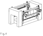
- Fig. 4:
- die Transfereinrichtung in der Stellung beim Werkzeugumrüsten (Parkposition),
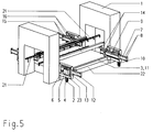
- Fig. 5:
- eine Transfereinrichtung mit auf dem Schiebetisch angeordneten Antriebseinheiten,
- Fig. 6:
- eine Darstellung des Sekundärbalkens,
- Fig 7:
- den Sekundärbalken im Längsschnitt,
- Fig. 8:
- den Sekundärbalken im Querschnitt - Schnitt A-A von Fig. 7 im vergrößerten Maßstab und
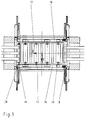
- Fig. 9:
- eine zweite Ausführung der Transfereinrichtung mit auf dem Schiebetisch angeordneten Antriebseinheiten.
- Fig. 1:
- 1 shows a schematic representation of the transfer device with drive units arranged on the press stands,
- Fig. 2:
- 1 in the working position for the parts transport in the longitudinal axis of the press line,
- Fig. 3:
- the transfer device in the working position for the parts feed transversely to the longitudinal axis of the press line (two parts running in opposite directions) and transport movement in the longitudinal axis of the press line (mixed operation),
- Fig. 4:
- the transfer device in the position during tool changeover (parking position),
- Fig. 5:
- a transfer device with drive units arranged on the sliding table,
- Fig. 6:
- a representation of the secondary bar,
- Fig 7:
- the secondary beam in longitudinal section,
- Fig. 8:
- the secondary bar in cross section - section AA of Fig. 7 on an enlarged scale and
- Fig. 9:
- a second embodiment of the transfer device with drive units arranged on the sliding table.
In einer ausgeführten Version der o.g. Transfereinrichtung (Fig. 1), ist eine Anordnung der zweidimensionalen Antriebseinheiten am Fressenständer 1 vorgesehen. Diese besteht jeweils aus einem Servoantrieb 2 zur Hubbewegung (z-Achse) mit einem Verbindungsgetriebe 3, vorzugsweise einem Zahnriemengetriebe zum synchronen Antrieb einer zweiten Antriebseinheit. Von diesem Servoantrieb 2 werden damit zwei Antriebsspindeln 4 zum Antrieb von Hubschlitten 5 bewegt. Die Hubschlitten 5 sind jeweils an zwei prallelen Führungssäulen 6 geführt.
An jedem Hubschlitten 5 ist weiterhin ein Träger 7 mit parallelen Führungen 8 zur Schließbewegung (y-Achse) befestigt, auf denen der Schließschlitten 9 bewegt wird. Als Antrieb dazu dient ein Servoantrieb 10, der ebenfalls mit einem Verbindungsgetriebe 11, vorzugsweise einem Zahnriemengetriebe, zum synchronen Antrieb eines zweiten Schließschlittens 9 (y-Achse) wirkverbunden ist. Dazu wird eine Antriebswelle 12 zur Übertragung eines Drehmomentes mit gleichzeitiger Verschiebbarkeit eines Lagers verwendet. Damit kann ein Umlenkgetriebe 13, z. B. ein Kegelradgetriebe, zum Antrieb des Schließschlittens 9 angetrieben werden.
Es ist ebenso möglich, daß die zweidimensionalen Antriebseinheiten ohne Verbindungsgetriebe 3, 11 mit jeweils separaten Servomotoren synchron angetrieben werden. Dabei ist es vorteilhaft, die Sekundärbalken 16 und die Führungsböcke 14 gelenkig mit einem zusätzlichen Längenausgleich zur Vermeidung des Verklemmens im Asynchronfall beider Antriebe zu verbinden.
Innerhalb eines Schließschlittens 9 dient eine Zahnriemenübersetzung zur Hubverdoppelung des Führungsbockes 14. An jedem Schließschlitten 9 befinden sich parallele Führungen 15, die dem Führungsbock 14 Lagestabilität verleihen. Mit Hilfe der Führungsböcke 14 werden die Sekundärbalken 16 entsprechend einem vorgegebenen Programm in Y- und Z-Richtung im Werkzeugraum der Presse bewegt.
Jeder Sekunderbalken 16 ist so gestaltet, daß er gleichzeitig zwei Primärbalken 17 mit Führungen 18, Spindelantrieben 19 und dazugehörigen Servoantrieben 20 aufnehmen kann (Figuren 6 bis 8).
Es ist ebenso denkbar, die außerhalb des Sekundärbalkens 16 angeordneten Servoantriebe 20 über entsprechende Umlenkmittel mit dem Primärbalken 17 zu verbinden.
Über Schnellspannsysteme werden an den Primärbalken 17 entsprechende werkzeugspezifische Greifer- oder Saugerleisten 21 befestigt. Die Primärbalken 17 sind bei reiner zweidimensionalen Bewegung in Pressenlinienlängsachse nach Fig. 2 (nur in z- und y-Richtung) antriebsseitig abgeschaltet. Sie können bei zwei- bzw. dreidimensionaler Bewegung quer zur Pressenlinienlängsachse nach Fig. 1 durch entsprechend programmierbare Steuerungen gleichzeitig oder gegenläufig bewegt werden. Damit ist es möglich, Platinen und Blechformteile entweder nur in der x-Richtung (Fig. 1) gleich- oder gegensinnig bzw. nur in der y-Richtung (Fig. 2) als auch gemischt in x- und y-Richtung (Fig. 3) zu bewegen.
Bei der gemischten Betriebsart nach Fig. 3 führen die Primärbalken 17 eines im Werkzeugraum angeordneten Sekundärbalkens 16 die Transportbewegung quer zur Pressenlinienlängsachse aus, wobei der zweite zur Transfereinrichtung gehörende Sekundärbalken 16 die weitere Transportbewegung in Pressenlinienlängsachse ausführt.
Bei Nichtgebrauch der Transfereinrichtung werden die Greifer- oder Saugerleisten 21 manuell oder automatisch an vorgesehenen Aufnahmestützen 25, die an den verfahrbaren Schiebetischen 22 angeordnet sind, deponiert. Die Sekundärbalken 16 werden dazu in eine "Parkposition" gefahren (Fig. 4), um den Werkzeugraum für spezielle Bedarfsfälle, z. B. Einrichten, ungehindert zugänglich zu machen.
In einer weiteren möglichen Ausführungsvariante (Fig. 5) ist die Transfereinrichtung nicht an den Pressenständern 1, sondern als komplette Einheit auf dem Schiebetisch 22 angeordnet. Diese besteht ebenfalls aus einem Servoantrieb 2 zur Hubbewegung (= z-Achse) mit einem Verbindungsgetriebe 3 zu einer zweiten, zum gleichen Sekundärbalken 16 gehörenden Antriebseinheit. Damit werden jeweils zwei Antriebsspindeln 4 zum Antrieb von Hubschlitten 5 bewegt. Die Hubschlitten 5 sind zusätzlich an jeweils zwei parallelen Führungssäulen 6 geführt.
An jedem Hubschlitten 5 ist ein Träger 7 mit parallelen Führungen 8 zur Schließbewegung (y-Achse) befestigt, auf dem der Schließschlitten 9 geführt wird. Der Antrieb hierzu ist ein Servoantrieb 10, der ebenfalls mit einem Verbindungsgetriebe 11, vorzugsweise einem Zahnriemengetriebe, zum synchronen Antrieb eines zweiten, zum gleichen Sekundärbalken 16 gehörenden Schließschlitten 9 versehen ist. Zum Antrieb der Schließschlitten 9 werden hier ebenfalls Antriebswellen 12 zur Übertragung eines Drehmomentes mit gleichzeitiger axialer Verschiebbarkeit des Lagers zum Angleichen an die Hubbewegung (x-Achse) verwendet. Damit kann ein Umlenkgetriebe 13, z. B. ein Kegelradgetriebe, zur Bewegung des Schließschlittens angetrieben werden.
Innerhalb eines Schließschlittens 9 dient eine Zahnriemenübersetzung zur Hubverdoppelung des Führungsbockes 14, um insbesondere bei eingeengten Platzverhältnissen einen größtmöglichen Transporthub in Pressenlinienlängsachse zu erreichen.
An jedem Schließschlitten 9 befinden sich zur Stabilität der jeweiligen Führungsböcke 14 parallele Führungen 15. Die gesamten Antriebe zur Schließ- und Hubbewegung (y-, z-Achse) werden jeweils durch ein Gestell 23 getragen. Die Gestelle 23 sind entsprechend auf dem Schiebetisch fixiert.In one version of the above-mentioned transfer device (FIG. 1), an arrangement of the two-dimensional drive units on the
A
It is also possible for the two-dimensional drive units to be driven synchronously without connecting gears 3, 11, each with separate servo motors. It is it is advantageous to articulate the
Within a
Each
It is also conceivable to connect the servo drives 20 arranged outside the
Appropriate tool-specific gripper or suction bars 21 are fastened to the
In the mixed operating mode according to FIG. 3, the
When the transfer device is not in use, the gripper or suction bars 21 are turned on manually or automatically provided support supports 25, which are arranged on the movable sliding tables 22, deposited. The
In a further possible embodiment variant (FIG. 5), the transfer device is not arranged on the press stands 1, but rather as a complete unit on the sliding table 22. This also consists of a
A
Within a
On each
Die Gestaltung der Sekundärbalken 16 mit den darin integrierten Servoantrieben 20 zum Teiletransport in der x-Achse ist identisch mit dem 1. Ausführungsbeispiel.
Als Parkposition kann bei dieser Variante die äußerste Stellung in der y-Achse dienen, um einen entsprechenden Freiraum zum Einrichten von Werkzeugen zu schaffen. Außerdem ist es möglich, die gesamte Transfereinrichtung mit dem Schiebetisch 22 aus dem Werkzeugraum der Presse herauszufahren und außerhalb der Presse eine Bewegungssimulation durchzuführen.The design of the
In this variant, the outermost position in the y-axis can serve as the parking position in order to create a corresponding free space for setting up tools. It is also possible to move the entire transfer device with the sliding table 22 out of the tool space of the press and to carry out a motion simulation outside the press.
Bei einer weiteren Ausführung der Transfereinrichtung nach Fig. 9 ist nur ein Primärbalken 17 je Sekundärbalken 16 angeordnet. Die Primärbalken 17 enthalten an den beiden äußeren Enden zugeordnete auf Greiferschiebern 24 angeordnete Greiferelemente, die auf diesen quer zur Pressenlinienlängsachse (x-Achse) verschiebbar sind. Während der Primärbalken 17 einen Transporthub entsprechend dem Werkzeugmittenabstand ausführt, wird die Bewegung der Greiferschieber der Primärbalkenbewegung überlagert. Dabei führt der in Transportrichtung eingefahrene Greiferschieber eine überlagerte, der Transportbewegung gegenläufige Bewegung aus.
In gleicher Weise führt der in Transportrichtung ausgefahrene letzte Greiferschieber ebenso eine der Transportbewegung gegenläufige Bewegung aus. Durch diese Relativbewegung ist der Abstand der Platinenübergabestation zur ersten Werkzeugstufe und der Abstand der letzten Werkzeugstufe zur Werkstückübergabestation nur ein Bruchteil des Werkzeugmittenabstandes.
Mit dieser Ausführung ist bei gleichzeitig entsprechend gestalteten Werkzeugen eine optimale Nutzung der Werkzeugspannfläche möglich, insbesondere dann, wenn durch die engen Ständeröffnungen der Presse ein Hineinragen der Sekundärbalken 16 nicht möglich ist.
Bei Anwendung der Ausführung nur im zwei- oder dreidimensionalen Betrieb quer zur Pressenlinienlängsachse (x-Achse) ist die modulare Erweiterung des Schließschlittens 9 mit einem durch Hubverdopplung überlagert angetriebenen Führungsbock 14 gemäß den vorstehend beschriebenen Ausführungsbeispielen nicht notwendig. Der Sekundärbalken 16 kann dann direkt auf dem Schließschlitten 9 angelenkt sein. Die Nutzung des separaten auf dem Schließschlitten 9 gelagerten Führungsbockes 14 ist weiterhin dann vorteilhaft, wenn eine zwischen dem Schließschlitten 9 und dem Führungsbock 14 angeordnete, im Ausführungsbeispiel nicht dargestellte, Überlastsicherung in Form eines fluidbeaufschlagten Zylinders genutzt wird, um unabhängig von der Programmsteuerung unter Vermeidung einer Havarie die Greifer schnell öffnen zu können.In a further embodiment of the transfer device according to FIG. 9, only one
In the same way, the last gripper slide extended in the transport direction also executes a movement opposite to the transport movement. As a result of this relative movement, the distance between the blank transfer station and the first tool level and the distance between the last tool level and the workpiece transfer station is only a fraction of the tool center distance.
With this design, optimal use of the tool clamping surface is possible with tools designed at the same time, in particular if the
When using the version only in two or three-dimensional operation transverse to the longitudinal axis of the press line (x-axis), the modular expansion of the
Claims (5)
dadurch gekennzeichnet,
daß an bzw. auf jedem Sekundärbalken (16) zwei mittels separater Antriebsmotoren quer zur Pressenlinienlängsachse in der gleichen Transportrichtung oder mit zueinander entgegengerichteter Transportrichtung verschiebbare Primärbalken (17) gelagert sind.Flexible transfer device according to claim 1,
characterized,
that on or on each secondary beam (16) two primary beams (17) which are displaceable by means of separate drive motors transversely to the longitudinal axis of the press line in the same transport direction or with a transport direction opposite to one another are mounted.
dadurch gekennzeichnet,
daß die den beiden äußeren Enden der Primärbalken (17) zugeordneten Greiferelemente auf Greiferschiebern angeordnet sind, die ihrerseits mittels separater Antriebe quer zur Pressenlinienlängsachse (in Richtung der X-Achse) verschiebbar auf den Primärbalken (17) gelagert sind.Flexible transfer device according to claim 1,
characterized,
that the gripper elements assigned to the two outer ends of the primary beams (17) are arranged on gripper slides, which in turn are mounted displaceably on the primary beam (17) by means of separate drives transversely to the longitudinal axis of the press line (in the direction of the X-axis).
dadurch gekennzeichnet,
daß auf den Schließschlitten (9) jeweils ein Führungsbock (14) mit Aufnahmen für die Sekundärbalken (16) in Pressenlinienlängsrichtung (in Richtung der Y-Achse) verschiebbar gelagert sind.Flexible transfer device according to claim 1,
characterized,
that a guide block (14) with receptacles for the secondary beams (16) is mounted displaceably in the longitudinal direction of the press line (in the direction of the Y axis) on the closing slide (9).
dadurch gekennzeichnet,
daß der Antrieb des Führungsbockes (14) mittels eines Zugmittelgetriebes zur Hubverdoppelung von der Bewegung des Schließschlittens (9) abgeleitet ist.Flexible transfer device according to claim 1,
characterized,
that the drive of the guide block (14) is derived from the movement of the closing slide (9) by means of a traction mechanism gear for doubling the stroke.
Applications Claiming Priority (2)
| Application Number | Priority Date | Filing Date | Title |
|---|---|---|---|
| DE4443546A DE4443546A1 (en) | 1994-12-07 | 1994-12-07 | Flexible transfer device for presses |
| DE4443546 | 1994-12-07 |
Publications (2)
| Publication Number | Publication Date |
|---|---|
| EP0715911A1 true EP0715911A1 (en) | 1996-06-12 |
| EP0715911B1 EP0715911B1 (en) | 2001-09-19 |
Family
ID=6535152
Family Applications (1)
| Application Number | Title | Priority Date | Filing Date |
|---|---|---|---|
| EP95117212A Expired - Lifetime EP0715911B1 (en) | 1994-12-07 | 1995-11-02 | Flexible transfer device for presses |
Country Status (3)
| Country | Link |
|---|---|
| EP (1) | EP0715911B1 (en) |
| DE (2) | DE4443546A1 (en) |
| ES (1) | ES2160657T3 (en) |
Cited By (3)
| Publication number | Priority date | Publication date | Assignee | Title |
|---|---|---|---|---|
| CN105129394A (en) * | 2015-08-21 | 2015-12-09 | 苏州博众精工科技有限公司 | Turning mechanism for assembling lines |
| CN115922827A (en) * | 2023-02-15 | 2023-04-07 | 邯郸理想包装机械有限公司 | Positioning and conveying device in block machining process |
| WO2023104242A1 (en) * | 2021-12-09 | 2023-06-15 | Aida Europe Gmbh | Transfer system for press lines |
Families Citing this family (5)
| Publication number | Priority date | Publication date | Assignee | Title |
|---|---|---|---|---|
| DE19636823B4 (en) * | 1996-09-11 | 2004-08-19 | Müller Weingarten AG | transfer device |
| DE10247782A1 (en) * | 2002-10-14 | 2004-04-22 | Otto Kaiser Gmbh | Press or punch |
| DE10336700B4 (en) * | 2003-08-09 | 2008-09-11 | Müller Weingarten AG | Transport device for blanks and workpieces in a press line or a press |
| DE102019009184B4 (en) | 2019-07-16 | 2023-11-30 | Strothmann Machines & Handling GmbH | PRESS LINE, COMPRISING LINEAR CONVEYOR FOR TRANSFERRING WORKPIECES BETWEEN TWO SUCCESSIVE POSITIONS IN A TRANSMISSION DIRECTION |
| CN112935748A (en) * | 2021-02-24 | 2021-06-11 | 上海天永智能装备股份有限公司 | Pneumatic pushing multi-position stop valve oil seal gripping device |
Citations (4)
| Publication number | Priority date | Publication date | Assignee | Title |
|---|---|---|---|---|
| DE2747237A1 (en) | 1977-10-21 | 1979-04-26 | Schuler Gmbh L | WORKPIECE TRANSPORT DEVICE |
| DE3238729A1 (en) * | 1981-10-23 | 1983-05-05 | Komatsu Mfg Co Ltd | Three-dimensional transfer feed device for a transfer press |
| DD258381A1 (en) | 1987-03-13 | 1988-07-20 | Warnke Umformtech Veb K | THREE-DIMENSIONAL DRIVE UNIT |
| DE3824058C1 (en) * | 1988-07-15 | 1989-11-30 | Maschinenfabrik Mueller-Weingarten Ag, 7987 Weingarten, De |
Family Cites Families (3)
| Publication number | Priority date | Publication date | Assignee | Title |
|---|---|---|---|---|
| DE4320430C2 (en) * | 1993-06-21 | 2003-11-20 | Mueller Weingarten Maschf | Transfer Press complex |
| DE4320431B4 (en) * | 1993-06-21 | 2004-08-19 | Müller Weingarten AG | Transfer Press complex |
| DE4421763C1 (en) * | 1994-06-22 | 1995-03-23 | Wild Maschinen Gmbh | Apparatus for the sorting of ready-assembled veneer sheets |
-
1994
- 1994-12-07 DE DE4443546A patent/DE4443546A1/en not_active Withdrawn
-
1995
- 1995-11-02 ES ES95117212T patent/ES2160657T3/en not_active Expired - Lifetime
- 1995-11-02 DE DE59509615T patent/DE59509615D1/en not_active Expired - Fee Related
- 1995-11-02 EP EP95117212A patent/EP0715911B1/en not_active Expired - Lifetime
Patent Citations (5)
| Publication number | Priority date | Publication date | Assignee | Title |
|---|---|---|---|---|
| DE2747237A1 (en) | 1977-10-21 | 1979-04-26 | Schuler Gmbh L | WORKPIECE TRANSPORT DEVICE |
| DE3238729A1 (en) * | 1981-10-23 | 1983-05-05 | Komatsu Mfg Co Ltd | Three-dimensional transfer feed device for a transfer press |
| DD258381A1 (en) | 1987-03-13 | 1988-07-20 | Warnke Umformtech Veb K | THREE-DIMENSIONAL DRIVE UNIT |
| DE3802481A1 (en) * | 1987-03-13 | 1988-09-22 | Warnke Umformtech Veb K | Three-dimensional drive unit |
| DE3824058C1 (en) * | 1988-07-15 | 1989-11-30 | Maschinenfabrik Mueller-Weingarten Ag, 7987 Weingarten, De |
Cited By (5)
| Publication number | Priority date | Publication date | Assignee | Title |
|---|---|---|---|---|
| CN105129394A (en) * | 2015-08-21 | 2015-12-09 | 苏州博众精工科技有限公司 | Turning mechanism for assembling lines |
| CN105129394B (en) * | 2015-08-21 | 2018-01-12 | 博众精工科技股份有限公司 | A kind of streamline steering mechanism |
| WO2023104242A1 (en) * | 2021-12-09 | 2023-06-15 | Aida Europe Gmbh | Transfer system for press lines |
| CN115922827A (en) * | 2023-02-15 | 2023-04-07 | 邯郸理想包装机械有限公司 | Positioning and conveying device in block machining process |
| CN115922827B (en) * | 2023-02-15 | 2023-05-05 | 邯郸理想包装机械有限公司 | Positioning and conveying device in block machining process |
Also Published As
| Publication number | Publication date |
|---|---|
| EP0715911B1 (en) | 2001-09-19 |
| ES2160657T3 (en) | 2001-11-16 |
| DE4443546A1 (en) | 1996-06-13 |
| DE59509615D1 (en) | 2001-10-25 |
Similar Documents
| Publication | Publication Date | Title |
|---|---|---|
| EP0672480B1 (en) | Transportsystem | |
| EP1313575B1 (en) | Articulated arm transport system | |
| EP3023170B1 (en) | Transfer device | |
| EP0773077B1 (en) | Press with combined transfer device | |
| EP0671228A2 (en) | Transporting equipment for work pieces in a press | |
| DE4309643C2 (en) | Transfer device for workpiece transport | |
| EP0715911B1 (en) | Flexible transfer device for presses | |
| DE3241844C1 (en) | Punching machine with revolver drum | |
| EP0901848A1 (en) | Transfer presses with automatic tool change | |
| DE102004051977B4 (en) | Device for transporting and changing the position of workpieces | |
| DD258381B1 (en) | THREE-DIMENSIONAL DRIVE UNIT FOR INPUT AND REMOVAL DEVICES FOR PRESSES AND TRANSPORT DEVICES BETWEEN PRESSES, ESPECIALLY FOR TRANSFER DEVICES IN PRESSES | |
| EP0642882B1 (en) | Palette changing apparatus for machine tools | |
| DE4320431B4 (en) | Transfer Press complex | |
| EP0194594A2 (en) | Thread and profile rolling machine | |
| DE19636823B4 (en) | transfer device | |
| DE4320430C2 (en) | Transfer Press complex | |
| DE19953049C2 (en) | Device for transporting molded parts | |
| DE3933888C2 (en) | Gripper bar changing device for automatic tool change on presses | |
| EP0423749B1 (en) | Stacker for work pieces in progressive presses | |
| DE102019003613A1 (en) | Process for processing workpieces made of wood, plastic and the like | |
| DE3831158A1 (en) | MACHINE TOOL | |
| DE4124228A1 (en) | Workpiece orienting fixture for machine tool - has hydraulic transmission with input coupling which can be engaged by NC machine spindle to index work | |
| DE3826827A1 (en) | Device for positioning workpieces | |
| EP1520640B1 (en) | Apparatus for transporting workpieces | |
| EP1563926B1 (en) | Apparatus and method for feeding workpieces |
Legal Events
| Date | Code | Title | Description |
|---|---|---|---|
| PUAI | Public reference made under article 153(3) epc to a published international application that has entered the european phase |
Free format text: ORIGINAL CODE: 0009012 |
|
| AK | Designated contracting states |
Kind code of ref document: A1 Designated state(s): DE ES FR GB IT SE |
|
| 17P | Request for examination filed |
Effective date: 19961118 |
|
| 17Q | First examination report despatched |
Effective date: 19980323 |
|
| GRAG | Despatch of communication of intention to grant |
Free format text: ORIGINAL CODE: EPIDOS AGRA |
|
| GRAG | Despatch of communication of intention to grant |
Free format text: ORIGINAL CODE: EPIDOS AGRA |
|
| GRAH | Despatch of communication of intention to grant a patent |
Free format text: ORIGINAL CODE: EPIDOS IGRA |
|
| GRAH | Despatch of communication of intention to grant a patent |
Free format text: ORIGINAL CODE: EPIDOS IGRA |
|
| GRAH | Despatch of communication of intention to grant a patent |
Free format text: ORIGINAL CODE: EPIDOS IGRA |
|
| GRAA | (expected) grant |
Free format text: ORIGINAL CODE: 0009210 |
|
| AK | Designated contracting states |
Kind code of ref document: B1 Designated state(s): DE ES FR GB IT SE |
|
| GBT | Gb: translation of ep patent filed (gb section 77(6)(a)/1977) |
Effective date: 20010919 |
|
| REF | Corresponds to: |
Ref document number: 59509615 Country of ref document: DE Date of ref document: 20011025 |
|
| REG | Reference to a national code |
Ref country code: ES Ref legal event code: FG2A Ref document number: 2160657 Country of ref document: ES Kind code of ref document: T3 |
|
| REG | Reference to a national code |
Ref country code: GB Ref legal event code: IF02 |
|
| ET | Fr: translation filed | ||
| PLBE | No opposition filed within time limit |
Free format text: ORIGINAL CODE: 0009261 |
|
| STAA | Information on the status of an ep patent application or granted ep patent |
Free format text: STATUS: NO OPPOSITION FILED WITHIN TIME LIMIT |
|
| 26N | No opposition filed | ||
| PGFP | Annual fee paid to national office [announced via postgrant information from national office to epo] |
Ref country code: DE Payment date: 20061107 Year of fee payment: 12 |
|
| PGFP | Annual fee paid to national office [announced via postgrant information from national office to epo] |
Ref country code: FR Payment date: 20061117 Year of fee payment: 12 |
|
| PGFP | Annual fee paid to national office [announced via postgrant information from national office to epo] |
Ref country code: SE Payment date: 20061123 Year of fee payment: 12 Ref country code: GB Payment date: 20061123 Year of fee payment: 12 Ref country code: ES Payment date: 20061123 Year of fee payment: 12 |
|
| PGFP | Annual fee paid to national office [announced via postgrant information from national office to epo] |
Ref country code: IT Payment date: 20061130 Year of fee payment: 12 |
|
| EUG | Se: european patent has lapsed | ||
| GBPC | Gb: european patent ceased through non-payment of renewal fee |
Effective date: 20071102 |
|
| PG25 | Lapsed in a contracting state [announced via postgrant information from national office to epo] |
Ref country code: SE Free format text: LAPSE BECAUSE OF NON-PAYMENT OF DUE FEES Effective date: 20071103 Ref country code: DE Free format text: LAPSE BECAUSE OF NON-PAYMENT OF DUE FEES Effective date: 20080603 |
|
| REG | Reference to a national code |
Ref country code: FR Ref legal event code: ST Effective date: 20080930 |
|
| PG25 | Lapsed in a contracting state [announced via postgrant information from national office to epo] |
Ref country code: GB Free format text: LAPSE BECAUSE OF NON-PAYMENT OF DUE FEES Effective date: 20071102 |
|
| REG | Reference to a national code |
Ref country code: ES Ref legal event code: FD2A Effective date: 20071103 |
|
| PG25 | Lapsed in a contracting state [announced via postgrant information from national office to epo] |
Ref country code: FR Free format text: LAPSE BECAUSE OF NON-PAYMENT OF DUE FEES Effective date: 20071130 Ref country code: ES Free format text: LAPSE BECAUSE OF NON-PAYMENT OF DUE FEES Effective date: 20071103 |
|
| PG25 | Lapsed in a contracting state [announced via postgrant information from national office to epo] |
Ref country code: IT Free format text: LAPSE BECAUSE OF NON-PAYMENT OF DUE FEES Effective date: 20071102 |