EP0715670B1 - Feuerschutzelement - Google Patents
Feuerschutzelement Download PDFInfo
- Publication number
- EP0715670B1 EP0715670B1 EP94924918A EP94924918A EP0715670B1 EP 0715670 B1 EP0715670 B1 EP 0715670B1 EP 94924918 A EP94924918 A EP 94924918A EP 94924918 A EP94924918 A EP 94924918A EP 0715670 B1 EP0715670 B1 EP 0715670B1
- Authority
- EP
- European Patent Office
- Prior art keywords
- fire barrier
- fabric
- barrier according
- flexible fire
- metal layer
- Prior art date
- Legal status (The legal status is an assumption and is not a legal conclusion. Google has not performed a legal analysis and makes no representation as to the accuracy of the status listed.)
- Expired - Lifetime
Links
- 230000004888 barrier function Effects 0.000 title claims abstract description 25
- 239000004744 fabric Substances 0.000 claims abstract description 47
- 239000002184 metal Substances 0.000 claims abstract description 16
- 229910052751 metal Inorganic materials 0.000 claims abstract description 16
- 239000010425 asbestos Substances 0.000 claims abstract description 5
- 229910052895 riebeckite Inorganic materials 0.000 claims abstract description 5
- 239000005030 aluminium foil Substances 0.000 claims description 9
- 238000005192 partition Methods 0.000 claims description 6
- 239000000853 adhesive Substances 0.000 claims description 5
- 230000001070 adhesive effect Effects 0.000 claims description 5
- 229910052500 inorganic mineral Inorganic materials 0.000 claims description 2
- 239000011707 mineral Substances 0.000 claims description 2
- 239000000470 constituent Substances 0.000 claims 1
- 230000008021 deposition Effects 0.000 claims 1
- 238000011065 in-situ storage Methods 0.000 claims 1
- 239000010410 layer Substances 0.000 description 19
- 239000011888 foil Substances 0.000 description 7
- 239000003365 glass fiber Substances 0.000 description 7
- 239000000463 material Substances 0.000 description 6
- 239000002131 composite material Substances 0.000 description 3
- 238000010276 construction Methods 0.000 description 3
- 239000004753 textile Substances 0.000 description 3
- 238000000034 method Methods 0.000 description 2
- 229920002972 Acrylic fiber Polymers 0.000 description 1
- 239000004831 Hot glue Substances 0.000 description 1
- 230000005540 biological transmission Effects 0.000 description 1
- 230000001680 brushing effect Effects 0.000 description 1
- 239000011248 coating agent Substances 0.000 description 1
- 238000000576 coating method Methods 0.000 description 1
- 238000002485 combustion reaction Methods 0.000 description 1
- 238000005137 deposition process Methods 0.000 description 1
- 230000009970 fire resistant effect Effects 0.000 description 1
- 238000009413 insulation Methods 0.000 description 1
- 239000011368 organic material Substances 0.000 description 1
- 230000037361 pathway Effects 0.000 description 1
- 230000000644 propagated effect Effects 0.000 description 1
- 238000000926 separation method Methods 0.000 description 1
- 239000002356 single layer Substances 0.000 description 1
Images
Classifications
-
- E—FIXED CONSTRUCTIONS
- E04—BUILDING
- E04B—GENERAL BUILDING CONSTRUCTIONS; WALLS, e.g. PARTITIONS; ROOFS; FLOORS; CEILINGS; INSULATION OR OTHER PROTECTION OF BUILDINGS
- E04B9/00—Ceilings; Construction of ceilings, e.g. false ceilings; Ceiling construction with regard to insulation
- E04B9/001—Ceilings; Construction of ceilings, e.g. false ceilings; Ceiling construction with regard to insulation characterised by provisions for heat or sound insulation
-
- E—FIXED CONSTRUCTIONS
- E04—BUILDING
- E04B—GENERAL BUILDING CONSTRUCTIONS; WALLS, e.g. PARTITIONS; ROOFS; FLOORS; CEILINGS; INSULATION OR OTHER PROTECTION OF BUILDINGS
- E04B9/00—Ceilings; Construction of ceilings, e.g. false ceilings; Ceiling construction with regard to insulation
- E04B9/30—Ceilings; Construction of ceilings, e.g. false ceilings; Ceiling construction with regard to insulation characterised by edge details of the ceiling; e.g. securing to an adjacent wall
- E04B9/303—Ceilings; Construction of ceilings, e.g. false ceilings; Ceiling construction with regard to insulation characterised by edge details of the ceiling; e.g. securing to an adjacent wall for flexible tensioned membranes
Definitions
- This invention relates to fire barriers.
- a fire barrier which is especially, but not exclusively, suitable for use in the area above a suspended ceiling.
- partition materials include fire resistant fabric curtains, typically made of asbestos cloth. The use of such cloth is particulary convenient, since it can be readily folded around cables, pipes and other obstructions.
- more recent partition materials include rigid building boards such as plasterboard though these require considerably more effort to install. More recently, it has been recognised that integrity alone is not enough. Fire can be propagated by ignition of combustible material in contact with the "cold" faces of such barriers and 15 minutes insulation (by which is meant that the temperature of the "cold" face shall not rise more than 140°C above ambient whilst the "hot” face follows the cellulosic curve of BS 476 Part 20) is now required by the Building Regulations (1991), for any cavity barrier greater than 1m by 1m in size.
- a flexible fire barrier comprises at least two non-asbestos heat-resistant fabric layers spaced apart to define an air gap therebetween, at least one surface of each fabric being coated with a reflective metal layer.
- the intermediate layer or layers are preferably coated on both faces with a reflective metal layer.
- a reflective metal layer particularly preferred heat-resistant fabrics include fabrics made from mineral fibres, especially glass fibre fabrics.
- the reflective metal layer is preferably an aluminium foil loosely attached to the fabric with or without the aid of an adhesive.
- the reflective metal layer may also be applied by a vacuum/vapour deposition process although discontinuous bonding is preferred.
- the fabric has a textured surface, being made from textured yarns or subsequently treated by a brushing/raising process. The fabric is preferably treated to enhance its resistance to heat/flame.
- the simple construction of this invention is capable of surviving a relatively severe fire test such as the one described earlier.
- a fire barrier was made from two glass fibre fabrics spaced apart 30mm. The inner or confronting fabric surfaces were loosely coated with an aluminium foil.
- the face opposite the one to which the fire was actually applied exhibited a temperature rise of only 88°C after thirty minutes.
- a single layer of the same fabric with the same aluminium foil applied to both faces survived only two minutes before the temperature on the non-exposed side exceeded 140°C.
- the construction is symmetrical, to ensure that the fire performance is as far as possible the same from both sides of the partition.
- confronting fabric surfaces are coated with a reflective metal layer.
- glass fibre fabrics In addition to the preferred glass fibre fabrics, it may also be possible to use specialised organic material such as, for example, partially carbonised acrylic fibres. However, such materials are relatively expensive and for that reason, glass fibre fabric, particularly when treated with proprietary high temperature fabric dressings, will be preferred for most applications. However, it is also possible that satisfactory results may be obtained by using as the fabric component, a high temperature paper material. Fabric in this present context thus includes papers and boards.
- the aluminium foil be bonded to the fabric
- the actual strength of the bond may not be critical since in use, the fixing system for the fire barrier will also help to support the metal foil.
- the foil should, however, be strong enough to withstand disruption of the adhesive system, at least for sufficiently long to pass the fire test. A certain amount of experimentation may be necessary in order to determine the appropriate type of metal foil to use with a particular fabric.
- the preferred discontinuous bonding of the foil to the fabric can be achieved in several ways.
- adhesive can be printed onto the foil and/or fabric as a pattern of isolated dots.
- Hot melt adhesive is also available in a mesh form.
- discontinuous bonding is to reduce transmission of heat, whilst at the same time optimising reflection of heat.
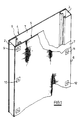
- a fire barrier in accordance with the present invention comprises a pair of generally vertically disposed side frames in the form of metal channel members 2, 3. It will be appreciated that these side frames are selected to suit a particular end use; they will be configured to fit into a specific roof space area as regards their height and lateral separation.
- the channels support two composite fabric layers 4, 5 which are spaced apart by the width of the channels.
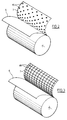
- Each composite fabric is made up of a textile fabric layer 6 and an aluminium foil layer 7, the two layers being relatively loosely bonded together, as for example by the methods illustrated in Figure 2 and Figure 3. It will be appreciated that relatively loose bonding can also be achieved in other ways.
- the layers may be bonded together only in the vicinity of their attachment to the supporting channel members 2, 3. This is illustrated in Figure 1, where the layers are shown attached to the channel members only by clips, 9, 10, 11 and 12 respectively.
- a roll of composite fabric layer comprises a textile fabric layer and an aluminium foil layer 7, the latter being pre-treated with an adhesive applied selectively as a pattern of dots 15 ( Figure 2) or as a mesh 16 ( Figure 3).
- a preferred textile fabric layer 6 is as woven glass fibre fabric, especially one treated with a heat resistant coating such as WELDSTOP (Registered trade mark) which enhances integrity under severe heat conditions.
- WELDSTOP Registered trade mark
Landscapes
- Engineering & Computer Science (AREA)
- Architecture (AREA)
- Physics & Mathematics (AREA)
- Electromagnetism (AREA)
- Civil Engineering (AREA)
- Structural Engineering (AREA)
- Building Environments (AREA)
- Laminated Bodies (AREA)
Claims (12)
- Biegsame Feuerschutzwand, umfassend mindestens zwei hitzebeständige, keinen Asbest enthaltende Textilschichten (6), so beabstandet voneinander, daß sie einen Luftspalt dazwischen festlegen, wobei mindestens eine Oberfläche von jedem Textil mit einer reflektierenden Metallschicht (7) beschichtet ist.
- Biegsame Feuerschutzwand nach Anspruch 1, wobei das Textil vollständig oder vorwiegend aus Mineralfasern besteht.
- Biegsame Feuerschutzwand nach Anspruch 1, wobei das Textil ein hochtemperaturbeständiges Papier oder ein hochtemperaturbeständiger Karton ist.
- Biegsame Feuerschutzwand nach einem vorangehenden Anspruch, wobei die Anordnung der Bestandteile symmetrisch ist, damit gewährleistet ist, daß die Eigenschaften beim Brand so weit wie möglich von beiden Seiten der Abtrennung dieselben sind.
- Biegsame Feuerschutzwand nach einem vorangehenden Anspruch, wobei die gegenüberliegenden Textilflächen mit einer reflektierenden Metallschicht (7) beschichtet sind.
- Biegsame Feuerschutzwand nach einem vorangehenden Anspruch, wobei die reflektierende Metallschicht (7) eine Aluminiumfolie ist.
- Biegsame Feuerschutzwand nach Anspruch 6, wobei die Aluminiumfolie eine einzelne Schicht ist, die mit einem Klebemittel an dem Textil befestigt ist.
- Biegsame Feuerschutzwand nach Anspruch 5, wobei die Aluminiumfolie durch Metallisieren oder Dampfabscheidung hergestellt wird.
- Biegsame Feuerschutzwand nach einem vorangehenden Anspruch, wobei die reflektierende Metallschicht diskontinuierlich an der Textiloberfläche befestigt ist.
- Biegsame Feuerschutzwand nach einem vorangehenden Anspruch mit drei voneinander beabstandeten Textilschichten, wobei die mittlere an jeder Seite eine reflektierende Metallschicht aufweist.
- Biegsame Feuerschutzwand nach einem vorangehenden Anspruch, wobei der Luftspalt im Bereich von etwa 10 mm bis 100 mm liegt.
- Biegsame Feuerschutzwand nach Anspruch 8, wobei der Luftspalt im Bereich 20 mm bis 50 mm liegt.
Applications Claiming Priority (3)
| Application Number | Priority Date | Filing Date | Title |
|---|---|---|---|
| GB9317688 | 1993-08-25 | ||
| GB9317688A GB2281322B (en) | 1993-08-25 | 1993-08-25 | Improved fire barrier |
| PCT/GB1994/001842 WO1995006173A1 (en) | 1993-08-25 | 1994-08-23 | Improved fire barrier |
Publications (2)
| Publication Number | Publication Date |
|---|---|
| EP0715670A1 EP0715670A1 (de) | 1996-06-12 |
| EP0715670B1 true EP0715670B1 (de) | 1997-11-26 |
Family
ID=10741022
Family Applications (1)
| Application Number | Title | Priority Date | Filing Date |
|---|---|---|---|
| EP94924918A Expired - Lifetime EP0715670B1 (de) | 1993-08-25 | 1994-08-23 | Feuerschutzelement |
Country Status (6)
| Country | Link |
|---|---|
| EP (1) | EP0715670B1 (de) |
| AU (1) | AU7502394A (de) |
| DE (1) | DE69407054T2 (de) |
| DK (1) | DK0715670T3 (de) |
| GB (1) | GB2281322B (de) |
| WO (1) | WO1995006173A1 (de) |
Cited By (1)
| Publication number | Priority date | Publication date | Assignee | Title |
|---|---|---|---|---|
| US8472189B2 (en) | 2006-05-20 | 2013-06-25 | Penny & Giles Aerospace Ltd. | Fireproof enclosure |
Families Citing this family (2)
| Publication number | Priority date | Publication date | Assignee | Title |
|---|---|---|---|---|
| US6572948B1 (en) | 2000-10-31 | 2003-06-03 | 3M Innovative Properties Company | Fire stop device with rupturable element |
| US8291660B2 (en) * | 2010-10-19 | 2012-10-23 | Mccary John M | Radiant insulating, venting and moisture control assembly |
Family Cites Families (5)
| Publication number | Priority date | Publication date | Assignee | Title |
|---|---|---|---|---|
| NL7205481A (de) * | 1971-04-30 | 1972-11-01 | ||
| GB1417863A (en) * | 1972-12-01 | 1975-12-17 | Rhys Davies Serives | Composite wall structures |
| DE3313526A1 (de) * | 1983-04-14 | 1983-09-15 | Georg Prof. Dr.-Ing. 4300 Essen Thierauf | Feuer- und hitzebestaendige wandelemente in leichtbauweise |
| US4935281A (en) * | 1989-04-05 | 1990-06-19 | Springs Industries, Inc. | Flame barrier office building materials |
| DE4036735C2 (de) * | 1989-11-18 | 1997-04-30 | Odenwald Faserplatten | Deckenelement für eine Brandschutz-Zwischendecke |
-
1993
- 1993-08-25 GB GB9317688A patent/GB2281322B/en not_active Expired - Fee Related
-
1994
- 1994-08-23 DK DK94924918T patent/DK0715670T3/da active
- 1994-08-23 WO PCT/GB1994/001842 patent/WO1995006173A1/en not_active Ceased
- 1994-08-23 EP EP94924918A patent/EP0715670B1/de not_active Expired - Lifetime
- 1994-08-23 AU AU75023/94A patent/AU7502394A/en not_active Abandoned
- 1994-08-23 DE DE69407054T patent/DE69407054T2/de not_active Expired - Fee Related
Cited By (1)
| Publication number | Priority date | Publication date | Assignee | Title |
|---|---|---|---|---|
| US8472189B2 (en) | 2006-05-20 | 2013-06-25 | Penny & Giles Aerospace Ltd. | Fireproof enclosure |
Also Published As
| Publication number | Publication date |
|---|---|
| GB2281322A (en) | 1995-03-01 |
| GB2281322B (en) | 1997-02-05 |
| WO1995006173A1 (en) | 1995-03-02 |
| DE69407054D1 (de) | 1998-01-08 |
| GB9317688D0 (en) | 1993-10-13 |
| DE69407054T2 (de) | 1998-06-10 |
| DK0715670T3 (da) | 1997-12-29 |
| AU7502394A (en) | 1995-03-21 |
| EP0715670A1 (de) | 1996-06-12 |
Similar Documents
| Publication | Publication Date | Title |
|---|---|---|
| EP0640038B1 (de) | Feuerbeständiger flexiblen Verbundwerkstoff, diesen einschliessendes System, Verfahren zur Herstellung des Verbundwerkstoffes und Verfahren zum Schutz vor Feuer | |
| US6128874A (en) | Fire resistant barrier for dynamic expansion joints | |
| US6131352A (en) | Fire barrier | |
| US6112488A (en) | Fire barrier material and gaskets therefor | |
| KR880003078A (ko) | 제조 및 건축용 비연소성 담요재 | |
| EP0346126A2 (de) | Feuerschutzmaterial | |
| US20090126297A1 (en) | Thermal insulation and sealing means for a safing slot | |
| JPH0243433A (ja) | 防火性伸縮継手 | |
| RU2462666C2 (ru) | Изоляция для вентиляционного трубопровода, проходящего через отверстие в стене или потолке | |
| KR102551777B1 (ko) | 방화단열댐퍼를 구비한 화재확산 방지용 덕트관연결구 | |
| US5402615A (en) | Fire retardant barrier system and method | |
| JP2537470Y2 (ja) | 第1のビル構造体及び第2のビル構造体間の膨張空間の防火被覆の為の装置 | |
| IE914461A1 (en) | Improvements in and relating to fire barriers and their method of manufacture | |
| EP1025320B1 (de) | Feuerbeständige dachkonstruktion | |
| CN1305560A (zh) | 用于电梯月台门的防火装置 | |
| WO1995006173A1 (en) | Improved fire barrier | |
| EP0761896B1 (de) | Systeme feuerwiderstandsfähiger Tafeln | |
| WO2009135811A1 (en) | Suspended ceiling with 3 layer ceiling plates | |
| EP0966578B1 (de) | Brandschutzelement | |
| EP0832333B1 (de) | Gegen hohe temperaturen beständiges isolationselement | |
| JP3142544B2 (ja) | 断熱スラット | |
| GB2149867A (en) | Insulated pipe support | |
| EP4696916A1 (de) | Passives brandschutzsystem für lufteinlasskanäle oder abzugskanäle | |
| KR20240155434A (ko) | 내화 발포 시트 및 이를 이용한 샌드위치 패널 | |
| GB2311006A (en) | Jointed flexible fire barriers |
Legal Events
| Date | Code | Title | Description |
|---|---|---|---|
| PUAI | Public reference made under article 153(3) epc to a published international application that has entered the european phase |
Free format text: ORIGINAL CODE: 0009012 |
|
| 17P | Request for examination filed |
Effective date: 19950913 |
|
| AK | Designated contracting states |
Kind code of ref document: A1 Designated state(s): BE DE DK IE IT NL |
|
| GRAG | Despatch of communication of intention to grant |
Free format text: ORIGINAL CODE: EPIDOS AGRA |
|
| 17Q | First examination report despatched |
Effective date: 19970214 |
|
| GRAH | Despatch of communication of intention to grant a patent |
Free format text: ORIGINAL CODE: EPIDOS IGRA |
|
| GRAH | Despatch of communication of intention to grant a patent |
Free format text: ORIGINAL CODE: EPIDOS IGRA |
|
| GRAH | Despatch of communication of intention to grant a patent |
Free format text: ORIGINAL CODE: EPIDOS IGRA |
|
| GRAA | (expected) grant |
Free format text: ORIGINAL CODE: 0009210 |
|
| ITF | It: translation for a ep patent filed | ||
| AK | Designated contracting states |
Kind code of ref document: B1 Designated state(s): BE DE DK IE IT NL |
|
| REG | Reference to a national code |
Ref country code: DK Ref legal event code: T3 |
|
| REF | Corresponds to: |
Ref document number: 69407054 Country of ref document: DE Date of ref document: 19980108 |
|
| PGFP | Annual fee paid to national office [announced via postgrant information from national office to epo] |
Ref country code: DK Payment date: 19980710 Year of fee payment: 5 |
|
| PGFP | Annual fee paid to national office [announced via postgrant information from national office to epo] |
Ref country code: IE Payment date: 19980717 Year of fee payment: 5 |
|
| PGFP | Annual fee paid to national office [announced via postgrant information from national office to epo] |
Ref country code: DE Payment date: 19980727 Year of fee payment: 5 |
|
| PGFP | Annual fee paid to national office [announced via postgrant information from national office to epo] |
Ref country code: NL Payment date: 19980728 Year of fee payment: 5 |
|
| PGFP | Annual fee paid to national office [announced via postgrant information from national office to epo] |
Ref country code: BE Payment date: 19980813 Year of fee payment: 5 |
|
| PLBE | No opposition filed within time limit |
Free format text: ORIGINAL CODE: 0009261 |
|
| STAA | Information on the status of an ep patent application or granted ep patent |
Free format text: STATUS: NO OPPOSITION FILED WITHIN TIME LIMIT |
|
| 26N | No opposition filed | ||
| PG25 | Lapsed in a contracting state [announced via postgrant information from national office to epo] |
Ref country code: IE Free format text: LAPSE BECAUSE OF NON-PAYMENT OF DUE FEES Effective date: 19990823 |
|
| PG25 | Lapsed in a contracting state [announced via postgrant information from national office to epo] |
Ref country code: DK Free format text: LAPSE BECAUSE OF NON-PAYMENT OF DUE FEES Effective date: 19990831 Ref country code: BE Free format text: LAPSE BECAUSE OF NON-PAYMENT OF DUE FEES Effective date: 19990831 |
|
| BERE | Be: lapsed |
Owner name: TBA INDUSTRIAL PRODUCTS LTD Effective date: 19990831 |
|
| PG25 | Lapsed in a contracting state [announced via postgrant information from national office to epo] |
Ref country code: NL Free format text: LAPSE BECAUSE OF NON-PAYMENT OF DUE FEES Effective date: 20000301 |
|
| REG | Reference to a national code |
Ref country code: DK Ref legal event code: EBP |
|
| NLV4 | Nl: lapsed or anulled due to non-payment of the annual fee |
Effective date: 20000301 |
|
| PG25 | Lapsed in a contracting state [announced via postgrant information from national office to epo] |
Ref country code: DE Free format text: LAPSE BECAUSE OF NON-PAYMENT OF DUE FEES Effective date: 20000601 |
|
| REG | Reference to a national code |
Ref country code: IE Ref legal event code: MM4A |
|
| PG25 | Lapsed in a contracting state [announced via postgrant information from national office to epo] |
Ref country code: IT Free format text: LAPSE BECAUSE OF NON-PAYMENT OF DUE FEES;WARNING: LAPSES OF ITALIAN PATENTS WITH EFFECTIVE DATE BEFORE 2007 MAY HAVE OCCURRED AT ANY TIME BEFORE 2007. THE CORRECT EFFECTIVE DATE MAY BE DIFFERENT FROM THE ONE RECORDED. Effective date: 20050823 |