EP0715487A2 - Process and circuit for starting and operating high pressure discharge lamps - Google Patents
Process and circuit for starting and operating high pressure discharge lamps Download PDFInfo
- Publication number
- EP0715487A2 EP0715487A2 EP95118397A EP95118397A EP0715487A2 EP 0715487 A2 EP0715487 A2 EP 0715487A2 EP 95118397 A EP95118397 A EP 95118397A EP 95118397 A EP95118397 A EP 95118397A EP 0715487 A2 EP0715487 A2 EP 0715487A2
- Authority
- EP
- European Patent Office
- Prior art keywords
- voltage
- operating
- electrodes
- starting
- lamp
- Prior art date
- Legal status (The legal status is an assumption and is not a legal conclusion. Google has not performed a legal analysis and makes no representation as to the accuracy of the status listed.)
- Granted
Links
Images


Classifications
-
- H—ELECTRICITY
- H05—ELECTRIC TECHNIQUES NOT OTHERWISE PROVIDED FOR
- H05B—ELECTRIC HEATING; ELECTRIC LIGHT SOURCES NOT OTHERWISE PROVIDED FOR; CIRCUIT ARRANGEMENTS FOR ELECTRIC LIGHT SOURCES, IN GENERAL
- H05B41/00—Circuit arrangements or apparatus for igniting or operating discharge lamps
- H05B41/02—Details
- H05B41/04—Starting switches
- H05B41/042—Starting switches using semiconductor devices
-
- H—ELECTRICITY
- H05—ELECTRIC TECHNIQUES NOT OTHERWISE PROVIDED FOR
- H05B—ELECTRIC HEATING; ELECTRIC LIGHT SOURCES NOT OTHERWISE PROVIDED FOR; CIRCUIT ARRANGEMENTS FOR ELECTRIC LIGHT SOURCES, IN GENERAL
- H05B41/00—Circuit arrangements or apparatus for igniting or operating discharge lamps
- H05B41/14—Circuit arrangements
- H05B41/26—Circuit arrangements in which the lamp is fed by power derived from dc by means of a converter, e.g. by high-voltage dc
- H05B41/28—Circuit arrangements in which the lamp is fed by power derived from dc by means of a converter, e.g. by high-voltage dc using static converters
- H05B41/288—Circuit arrangements in which the lamp is fed by power derived from dc by means of a converter, e.g. by high-voltage dc using static converters with semiconductor devices and specially adapted for lamps without preheating electrodes, e.g. for high-intensity discharge lamps, high-pressure mercury or sodium lamps or low-pressure sodium lamps
- H05B41/2881—Load circuits; Control thereof
- H05B41/2882—Load circuits; Control thereof the control resulting from an action on the static converter
-
- H—ELECTRICITY
- H05—ELECTRIC TECHNIQUES NOT OTHERWISE PROVIDED FOR
- H05B—ELECTRIC HEATING; ELECTRIC LIGHT SOURCES NOT OTHERWISE PROVIDED FOR; CIRCUIT ARRANGEMENTS FOR ELECTRIC LIGHT SOURCES, IN GENERAL
- H05B41/00—Circuit arrangements or apparatus for igniting or operating discharge lamps
- H05B41/14—Circuit arrangements
- H05B41/36—Controlling
- H05B41/38—Controlling the intensity of light
- H05B41/382—Controlling the intensity of light during the transitional start-up phase
- H05B41/388—Controlling the intensity of light during the transitional start-up phase for a transition from glow to arc
-
- Y—GENERAL TAGGING OF NEW TECHNOLOGICAL DEVELOPMENTS; GENERAL TAGGING OF CROSS-SECTIONAL TECHNOLOGIES SPANNING OVER SEVERAL SECTIONS OF THE IPC; TECHNICAL SUBJECTS COVERED BY FORMER USPC CROSS-REFERENCE ART COLLECTIONS [XRACs] AND DIGESTS
- Y02—TECHNOLOGIES OR APPLICATIONS FOR MITIGATION OR ADAPTATION AGAINST CLIMATE CHANGE
- Y02B—CLIMATE CHANGE MITIGATION TECHNOLOGIES RELATED TO BUILDINGS, e.g. HOUSING, HOUSE APPLIANCES OR RELATED END-USER APPLICATIONS
- Y02B20/00—Energy efficient lighting technologies, e.g. halogen lamps or gas discharge lamps
-
- Y—GENERAL TAGGING OF NEW TECHNOLOGICAL DEVELOPMENTS; GENERAL TAGGING OF CROSS-SECTIONAL TECHNOLOGIES SPANNING OVER SEVERAL SECTIONS OF THE IPC; TECHNICAL SUBJECTS COVERED BY FORMER USPC CROSS-REFERENCE ART COLLECTIONS [XRACs] AND DIGESTS
- Y10—TECHNICAL SUBJECTS COVERED BY FORMER USPC
- Y10S—TECHNICAL SUBJECTS COVERED BY FORMER USPC CROSS-REFERENCE ART COLLECTIONS [XRACs] AND DIGESTS
- Y10S315/00—Electric lamp and discharge devices: systems
- Y10S315/02—High frequency starting operation for fluorescent lamp
-
- Y—GENERAL TAGGING OF NEW TECHNOLOGICAL DEVELOPMENTS; GENERAL TAGGING OF CROSS-SECTIONAL TECHNOLOGIES SPANNING OVER SEVERAL SECTIONS OF THE IPC; TECHNICAL SUBJECTS COVERED BY FORMER USPC CROSS-REFERENCE ART COLLECTIONS [XRACs] AND DIGESTS
- Y10—TECHNICAL SUBJECTS COVERED BY FORMER USPC
- Y10S—TECHNICAL SUBJECTS COVERED BY FORMER USPC CROSS-REFERENCE ART COLLECTIONS [XRACs] AND DIGESTS
- Y10S315/00—Electric lamp and discharge devices: systems
- Y10S315/05—Starting and operating circuit for fluorescent lamp
Definitions
- the invention relates to a method for starting and operating high-pressure discharge lamps according to the preamble of claim 1, and to a circuit arrangement for carrying out the method according to claim 1.
- high-pressure discharge lamps is to be understood as meaning lamps with at least two main electrodes arranged within a discharge vessel, between which a high-current arc discharge is formed during operation, for example metal halide, sodium vapor or noble gas arc lamps.
- a high-current arc discharge is formed during operation
- metal halide, sodium vapor or noble gas arc lamps for example metal halide, sodium vapor or noble gas arc lamps.
- the initially electrically insulating (ignition) gas is ionized between the electrodes and the lamp current increases rapidly.
- the initially cold electrodes and the discharge vessel heat up to operating temperature.
- the hot electrodes deliver the free electrons necessary for maintaining the arc discharge by means of glow emission.
- high-voltage pulses are usually applied to the lamp electrodes (e.g. DE-OS 42 27 427).
- the resulting electrical field between the electrodes accelerates the free primary electrons generated by the ionizing ambient radiation (e.g. high-level radiation) and field emission in order to trigger new secondary electrons by means of charge carrier bombardment from the electrode surfaces and thus start a charge carrier avalanche.
- the lamp filler for example, the Krypton-85 beta emitter can be mixed.
- Another measure consists in doping the electrodes with thorium ( ⁇ -emitter), which also causes the Electron work function decreased.
- ⁇ -emitter thorium
- the electrodes are increasingly heated by the charge carrier bombardment. As the temperature rises, the glow emission from the electrodes becomes more important as an efficient mechanism for generating free electrons. As a result, the ionization of the lamp filling between the electrodes continues to increase until a stationary arc discharge is formed if the conductivity is sufficiently high.
- the time period between the ionization of the filling and the formation of the arc discharge, which " takes over" the initial glow discharge, is also referred to as the takeover time.
- the takeover phase is usually followed by a run-up phase during which the lamp heats up to its stationary temperature. Only after this run-up phase has been completed is the operating voltage at the lamp electrodes set to a steady-state value for the arc operating voltage.
- US Pat. No. 4,331,905 discloses a circuit arrangement for starting and operating gas discharge lamps. In addition to a ballast for lamp operation, this also includes a high-frequency circuit which provides a high ignition voltage required for igniting cold or re-igniting hot lamps. According to the functioning of this circuit arrangement, both the operating voltage of the ballast and the high-frequency ignition voltage are applied to the lamp electrodes during the starting phase. After the lamp filling has been ionized, the high-frequency ignition voltage is switched off.
- a disadvantage of these solutions is that, particularly during the ignition phase, but also during the takeover phase, local overheating and sputtering processes initially occur due to field emission due to the - possibly pulsed - high electrical ignition field strengths on the electrode surfaces. As long as the electrodes are still cold, particles are released from these surfaces, among other things by charge carriers hitting the electrode surfaces. As a result, electrode material is atomized during each starting process, and this material is partially deposited on the inner wall of the discharge vessel. This leads to increasing blackening of the vessel and consequently to a reduction in the luminous efficacy of the lamp. In addition, the ignition voltage is essentially used only to ignite one Auxiliary glow discharge with relatively low power conversion.
- the heating power required to form the arc discharge - ie the actual main discharge - to reach the glow temperature of the electrodes is only provided by the operating voltage during the takeover phase.
- the takeover phase takes a relatively long time and thus also contributes to the atomization of electrode material and consequently to the blackening of the discharge vessel.
- the invention has for its object to eliminate the disadvantages mentioned and to provide a method for starting and operating discharge lamps that shortens the takeover time for the formation of the arc. Another aspect of the invention is to ensure reliable ignition of the discharge with the lowest possible ignition voltage, even without radioactive additives in the lamp. This object is achieved according to the invention by the characterizing features of claim 1. Further advantageous features of the invention are explained in the dependent claims.
- Another object is to provide a circuit arrangement with which the proposed method can be carried out. This object is achieved by a circuit arrangement with features according to claim 15. Further advantageous embodiments of the arrangement are explained in the dependent claims.
- the basic idea of the invention is to apply a high-frequency alternating voltage - hereinafter referred to as the starting voltage - to the lamp electrodes, which is specifically selected so that free electrons are generated essentially only in the space between the electrodes by impact ionization of the gas particles during the ignition phase.
- the secondary electron emission on the surface of the still cold electrodes initially plays no role.
- Another important feature is that, by means of the high-frequency electrical field generated by the starting voltage, a sufficiently high electrical HF power is provided for rapid heating of the electrodes.
- the operating voltage of the lamp is only switched to the electrodes after a preheating phase. The electrodes are then heated to the annealing temperature and are therefore able to supply enough electrons for the high-current arc discharge by means of annealing emissions.
- the transfer time is significantly reduced. This goes with a corresponding reduction in the starting phase - i.e. the ignition, heating and takeover phase - accompanied by sputtering processes occurring on the electrode surfaces.
- the resulting decisive advantage is a lower bulb blackening and consequently an improved maintenance or longer lamp life.
- the cold filling pressure can be increased significantly compared to previous ignition techniques and consequently the sputtering of electrode material during the ignition phase can be further reduced.
- the argon partial pressure can be increased from typically approx. 150 hPa to over 300 hPa, while maintaining a short ignition and takeover time.
- an increase in the xenon partial pressure is of further importance in addition to the improved maintenance.
- an increase in luminous flux of approx. 2 lm can be achieved for each hPa pressure increase.
- lamps with relatively long ignition and takeover times e.g. Lamps with unthorated electrodes and without the addition of krypton, and surprisingly in some cases even lamps that cannot be ignited by conventional ignition technology with the aid of the invention, ignite within a short time and then burn reliably.
- Direct or alternating voltages are used for the operating voltage, tailored to the requirements of the lamp to be operated.
- the mains frequency (50 Hz) and frequencies of a few 10 kHz, as are customary in electronic ballasts, are of practical importance for AC operation.
- the amplitude of the operating voltage at the electrodes corresponds to the operating voltage of the discharge arc.
- Typical (effective) values are in the order of magnitude between approx. 10 V and 100 V.
- the starting voltage has proven to be advantageous for the starting voltage to select the frequency in such a way that the product of the frequency f of the starting voltage and the electrode spacing d is the condition fd ⁇ 50kHzcm Fulfills.
- the oscillation amplitude of the electrons, and even more so of the heavier ions is small enough to keep losses due to oscillatory drift to the electrode surfaces and undesirable electrode effects associated with charge carrier bombardment for the majority of the charge carriers during the ignition phase.
- the coupling and line losses generally increase with increasing frequency.
- frequencies in the range between approx. 100 kHz and 200 kHz have proven to be useful with conventional RF excitation techniques based on the oscillator-amplifier principle.
- suitable stimulus concepts e.g. According to the principle of the cantilever chair, it is also possible to couple HF powers of higher frequencies into the discharge with little loss.
- Suitable peak values for the RF field strength are in the range between approximately 1 kV / cm and 6 kV / cm, preferably between 2.5 kV / cm and 4.5 kV / cm.
- E HF ie E HF / p
- the peak value of the starting voltage U is S HF in the range between approx. 1.5 kV and 3.5 kV, preferably in the range between approx. 2 kV and 3 kV.
- the duration of the takeover time essentially depends on the efficiency of the glow emission from the electrodes. It is therefore determined by the preheating power for the electrodes, i.e. the high-frequency starting power, as well as selectively influenced by the duration of the preheating phase.
- the average high-frequency starting power is approximately 0.2 to 0.7 times the operating power, preferably 0.3 to 0.6 times.
- the preheating time ⁇ t H is up to approx. 3 s depending on the level of the medium high-frequency starting power, typically it is in the range between 0.1 s and 1.5 s. After that, the electrodes are already incandescent.
- the high-frequency starting voltage can in principle also be applied to the electrodes during stationary operation of the lamp.
- no particular advantages are currently discernible, so that this variant appears to be obsolete.
- the duration of the overlap time is variably matched to the takeover time of the respective lamp.
- the end of the overlap time ⁇ t Ü is derived from the voltage jump at the lamp electrodes from the no-load supply voltage to the arc discharge arc voltage.
- the start voltage is switched off a few seconds after the usual takeover time of common discharge lamps has elapsed, for example after 5 s.
- the overlap time is fixed.
- the duration of the heating-up time, typically approx.0.5 s, and the high-frequency heating power, typically approx. Half the operating power, are so dimensioned that the arc transfer takes place very quickly, typically within approx. 0, when the operating voltage is switched on , 1 s to 0.2 s.
- An overlap time that is slightly longer than the takeover time, for example 0.3 s, ensures that the arc has developed before the starting voltage is switched off.
- a higher control effort has to be accepted when implementing this variant of the method.
- the starting voltage is only switched off at the moment when the operating voltage at the lamp electrodes is present.
- the simplest solution in practice remains to connect the operating voltage to the starting voltage after the preheating time and to switch off the starting voltage only after an overlap time.
- a basic circuit arrangement for implementing the method according to the invention has an operating device connected to a first switch and an HF ignition device connected to a second switch, and a timer controlling the two switches. Both the output of the operating voltage supplying The control gear and the output of the HF ignition device supplying the high-frequency starting voltage are connected to the lamp electrodes at the same time or at different times in accordance with the time program of the timer.
- a blocking element for example a choke, decouples the high frequency from the output of the operating device.
- the HF ignition device consists of an HF power oscillator for generating the high frequency and a downstream resonant circuit, e.g. from a series connection of a capacitor and a coil, which increases the amplitude of the high frequency to the required high voltage.
- the advantage of this superimposition technology is the problem-free and cost-effective replacement of conventional ignitors in existing ballasts by the HF superimposed ignitor including switch and timer.
- FIG. 1 shows a basic flow diagram of the method according to the invention.
- the start voltage U HF is applied to the electrodes of the discharge lamp. This starts the ignition and preheating phase ZH, during which the high-frequency electric field establishes a discharge between the electrodes and the electrodes are heated to the annealing temperature.
- an arc discharge forms between the electrodes that are now capable of glow emission and ends the takeover phase Ü.
- Figure 2 shows - using the example of two 70 W metal halide discharge lamps with unthorated electrodes and an ignition gas pressure of approx. 130 hPa (argon) - a schematic (not to scale) comparison of the duration of the starting phases when using two conventional ignition methods a, b and the invention Procedure c.
- the times t 1, t S for switching on the operating voltage or the complete formation of the arc - ie the end of the takeover phase - are drawn on time axes t.
- the marked points in time were taken from oscillographic recordings of the time profile of the respective electrode voltage.
- the voltage jump to the arc voltage was selected as the time t S.
- Case a shows the result when using an inductive ballast including conventional ignition circuit.
- the mains voltage U B and an up to the arc takeover sequence of high-voltage pulses U P were placed on the lamp electrodes.
- the arc of lamp 1 was completely formed. The lamp 2, however, could not be ignited.
- FIG. 3 shows a block diagram of a basic circuit arrangement for carrying out the method according to FIG. 1. It essentially consists of an operating device V supplying the operating voltage, an HF ignition device Z for generating the high-frequency starting voltage and two controlled by a timer T and with the HF -Ignition or control gear connected switches S1 and S2. Both the operating device V and the HF ignition device Z are connected to the discharge lamp EL.
- An HF blocking element SG between control gear V and discharge lamp EL on the one hand and control gear V and HF ignition device Z on the other hand prevents the starting voltage from being coupled into control gear V during the overlap phase.
- FIG. 4 shows an expanded block diagram of a circuit arrangement according to FIG. 3. It consists of a conventional inductive ballast V operated with 230 V and 50 Hz mains voltage, an HF power oscillator HF according to known circuit principles, which generate a high-frequency voltage and form an HF superimposed ignitor with the downstream series resonant circuit consisting of coil L and capacitor C3, as well as two by means of a timer circuit T, known per se - implemented here by comparators with switching delay determined by RC elements - controlled switches S1, S2.
- the ballast V consists of a series ballast choke Dr1 to limit the lamp current and a compensation capacitor C1 connected in parallel to the input 1, 2 to improve the power factor.
- the two input terminals 1, 2 of the ballast V are connected to the mains voltage.
- the timer circuit T is fed from the output 3, 4 of the operating device V.
- the timer circuit T is connected on the one hand via a diode D to the series choke Dr1 and on the other hand to the base of the compensation capacitor C1.
- the input 5, 6 of the HF power oscillator HF is fed in a similar manner.
- a first input terminal 5 of the HF power oscillator HF is contacted with the connection point between the diode D and the timer circuit T.
- the second input terminal 6 of the HF power oscillator HF is connected to the base point of the compensation capacitor C1 via a first switch S1, for example a semiconductor switch.
- the switch S1 switches on the HF power oscillator HF for the duration of the ignition and preheating phase as well as the overlap phase.
- the connection point between the series choke Dr1 and the diode D is connected to a first electrode of the discharge lamp EL via a second switch S2, for example a mechanical relay, and via a choke Dr2 and a coil L.
- the second electrode of the discharge lamp EL is in contact with the base of the compensation capacitor C1. After the preheating time, the switch S2 thus connects the operating device V to the discharge lamp EL.
- the capacitor C3 connects a first output terminal 8 of the RF power oscillator to the first electrode of the discharge lamp EL.
- the capacitor C3 forms, together with the coil L, a series resonant circuit which provides the amplitude of the high-frequency starting voltage required to ignite the lamp filling at the electrodes of the lamp EL by means of excessive resonance.
- the inductor Dr2 acts as an HF block between the output of the HF power oscillator HF and the series inductor Dr1 of the operating device V.
- the connection point between the inductor Dr2 and the coil L is connected via a coupling capacitor C2 to the second output terminal 7 of the HF power oscillator. On the one hand, it couples the HF current into the series resonance circuit and, on the other hand, it galvanically separates the mains voltage from the HF part.
- the advantage of this arrangement is the possibility of a problem-free replacement of conventional ignition devices by the HF ignition device including the associated switches S1, S2 and the timer T.
- FIG. 5 shows a comparison of measured luminous fluxes (Y1 axis) as a function of the cumulative number of ignitions (X axis) for lamps with an HF igniter (curve 1) or a conventional igniter (curve 2).
- the cumulative number was realized in such a way that the lamps were switched on and off once every hour during operation. This means that the number of switching operations (values on the X axis) corresponds to the operating time in hours.
- the Y1 coordinates thus indicate the luminous flux of the lamps in kilolumens (klm) for the number of ignitions carried out up to the time of the respective luminous flux measurement.
- the measurements were carried out on 70 W metal halide discharge lamps with thoriated electrodes but without the addition of Kr85.
Abstract
Description
Die Erfindung betrifft ein Verfahren zum Starten und Betreiben von Hochdruck-Entladungslampen gemäß dem Oberbegriff des Anspruchs 1, sowie eine Schaltungsanordnung zur Durchführung des Verfahrens gemäß Anspruch 1.The invention relates to a method for starting and operating high-pressure discharge lamps according to the preamble of
Unter der Bezeichnung Hochdruck-Entladungslampen sind Lampen mit mindestens zwei innerhalb eines Entladungsgefäßes angeordneten Hauptelektroden, zwischen denen sich im Betrieb eine stromstarke Bogenentladung ausbildet, zu verstehen, beispielsweise Metallhalogenid-, Natriumdampf- oder Edelgas-Bogenlampen. Während des Zündvorgangs wird das zunächst elektrisch isolierende (Zünd)Gas zwischen den Elektroden ionisiert, und der Lampenstrom nimmt rasch zu. Im Verlaufe der folgenden Hochlaufphase erwärmen sich die zunächst kalten Elektroden sowie das Entladungsgefäß auf Betriebstemperatur. Im anschließenden stationären Betrieb liefern die heißen Elektroden durch Glühemission die für die Aufrechterhaltung der Bogenentladung notwendigen freien Elektronen.The term high-pressure discharge lamps is to be understood as meaning lamps with at least two main electrodes arranged within a discharge vessel, between which a high-current arc discharge is formed during operation, for example metal halide, sodium vapor or noble gas arc lamps. During the ignition process, the initially electrically insulating (ignition) gas is ionized between the electrodes and the lamp current increases rapidly. In the course of the following startup phase, the initially cold electrodes and the discharge vessel heat up to operating temperature. In the subsequent stationary operation, the hot electrodes deliver the free electrons necessary for maintaining the arc discharge by means of glow emission.
Zum Zünden der Lampenfüllung werden üblicherweise Hochspannungspulse an die Lampenelektroden gelegt (z.B. DE-OS 42 27 427). Das resultierende elektrische Feld zwischen den Elektroden beschleunigt die durch die ionisierende Umgebungsstrahlung (z.B. Höhenstrahlung) sowie durch Feldemission erzeugten freien Primärelektronen, um mittels Ladungsträgerbombardement aus den Elektrodenoberflächen neue Sekundärelektronen auszulösen und so eine Ladungsträgerlawine zu starten.To ignite the lamp filling, high-voltage pulses are usually applied to the lamp electrodes (e.g. DE-OS 42 27 427). The resulting electrical field between the electrodes accelerates the free primary electrons generated by the ionizing ambient radiation (e.g. high-level radiation) and field emission in order to trigger new secondary electrons by means of charge carrier bombardment from the electrode surfaces and thus start a charge carrier avalanche.
Häufig ist es erforderlich, die Zündung durch Zugabe radioaktiver Stoffe zu unterstützen. Die von diesen Stoffen ausgesandte ionisierende Strahlung erhöht unter anderem die Dichte der Primärelektronen und erleichtert so den Aufbau einer Ladungsträgerlawine zwischen den Elektroden. Zu diesem Zweck kann der Lampenfüllung z.B. der β-Strahler Krypton-85 zugemischt sein. Eine weitere Maßnahme besteht in der Dotierung der Elektroden mit Thorium (α-Strahler), wodurch sich außerdem die Elektronenaustrittsarbeit erniedrigt. Allerdings sind allgemein Bestrebungen im Gange, auf radioaktive Zusätze zu verzichten.It is often necessary to support the ignition by adding radioactive substances. The ionizing radiation emitted by these substances increases, among other things, the density of the primary electrons and thus facilitates the build-up of a charge carrier avalanche between the electrodes. For this purpose, the lamp filler, for example, the Krypton-85 beta emitter can be mixed. Another measure consists in doping the electrodes with thorium (α-emitter), which also causes the Electron work function decreased. However, efforts are generally underway to dispense with radioactive additives.
Während der Startphase werden die Elektroden durch das Ladungsträgerbombardement zunehmend aufgeheizt. Mit steigender Temperatur gewinnt die Glühemission der Elektroden als effizienter Mechanismus zur Erzeugung freier Elektronen an Bedeutung. Folglich nimmt die Ionisierung der Lampenfüllung zwischen den Elektroden weiter zu, bis sich bei ausreichend hoher Leitfähigkeit eine stationäre Bogenentladung ausbildet. Die Zeitdauer zwischen der Ionisierung der Füllung und der Ausbildung der Bogenentladung, welche die anfängliche Glimmentladung "übernimmt", wird auch als Übernahmezeit bezeichnet.During the starting phase, the electrodes are increasingly heated by the charge carrier bombardment. As the temperature rises, the glow emission from the electrodes becomes more important as an efficient mechanism for generating free electrons. As a result, the ionization of the lamp filling between the electrodes continues to increase until a stationary arc discharge is formed if the conductivity is sufficiently high. The time period between the ionization of the filling and the formation of the arc discharge, which " takes over" the initial glow discharge, is also referred to as the takeover time.
Der Übernahmephase folgt in der Regel eine Hochlaufphase, während der sich die Lampe auf ihre stationäre Temperatur aufheizt. Erst nach Abschluß dieser Hochlaufphase stellt sich die Betriebsspannung an den Lampenelektroden auf einen stationären Wert der Bogenbrennspannung ein.The takeover phase is usually followed by a run-up phase during which the lamp heats up to its stationary temperature. Only after this run-up phase has been completed is the operating voltage at the lamp electrodes set to a steady-state value for the arc operating voltage.
In der US-PS 4 331 905 ist eine Schaltungsanordnung zum Starten und Betreiben von Gasentladungslampen offenbart. Diese beinhaltet neben einem Vorschaltgerät für den Lampenbetrieb zusätzlich eine Hochfrequenzschaltung, die eine für das Zünden von kalten bzw. Wiederzünden von heißen Lampen erforderlich hohe Zündspannung bereitstellt. Gemäß der Funktionsweise dieser Schaltungsanordnung liegen während der Startphase sowohl die Betriebsspannung des Vorschaltgeräts als auch die hochfrequente Zündspannung an den Lampenelektroden. Nach erfolgter Ionisierung der Lampenfüllung wird die hochfrequente Zündspannung abgeschaltet.US Pat. No. 4,331,905 discloses a circuit arrangement for starting and operating gas discharge lamps. In addition to a ballast for lamp operation, this also includes a high-frequency circuit which provides a high ignition voltage required for igniting cold or re-igniting hot lamps. According to the functioning of this circuit arrangement, both the operating voltage of the ballast and the high-frequency ignition voltage are applied to the lamp electrodes during the starting phase. After the lamp filling has been ionized, the high-frequency ignition voltage is switched off.
Nachteilig bei diesen Lösungen ist, daß, insbesondere während der Zündphase, aber auch während der Übernahmephase aufgrund der - ggf. impulsartigen - hohen elektrischen Zündfeldstärken auf den Elektrodenoberflächen zunächst durch Feldemission lokale Überhitzungen sowie Sputterprozesse auftreten. Solange die Elektroden noch kalt sind, werden dabei, unter anderem durch auf die Elektrodenoberflächen auftreffende Ladungsträger, Teilchen aus diesen Oberflächen ausgelöst. Dadurch wird bei jedem Startvorgang Elektrodenmaterial zerstäubt, welches sich teilweise an der Innenwandung des Entladungsgefäßes niederschlägt. Dies führt zur zunehmenden Schwärzung des Gefäßes und folglich zur Verminderung der Lichtausbeute der Lampe. Außerdem dient die Zündspannung im wesentlichen nur zur Zündung einer Hilfs-Glimmentladung mit relativ geringem Leistungsumsatz. Die zur Ausbildung der Bogenentladung - d.h. der eigentlichen Hauptentladung - notwendige Heizleistung zum Erreichen der Glühtemperatur der Elektroden wird erst während der Übernahmephase durch die Betriebsspannung bereitgestellt. Dadurch dauert die Übernahmephase relativ lange und trägt so ebenfalls zur Zerstäubung von Elektrodenmaterial und folglich zur Schwärzung des Entladungsgefäßes bei.A disadvantage of these solutions is that, particularly during the ignition phase, but also during the takeover phase, local overheating and sputtering processes initially occur due to field emission due to the - possibly pulsed - high electrical ignition field strengths on the electrode surfaces. As long as the electrodes are still cold, particles are released from these surfaces, among other things by charge carriers hitting the electrode surfaces. As a result, electrode material is atomized during each starting process, and this material is partially deposited on the inner wall of the discharge vessel. This leads to increasing blackening of the vessel and consequently to a reduction in the luminous efficacy of the lamp. In addition, the ignition voltage is essentially used only to ignite one Auxiliary glow discharge with relatively low power conversion. The heating power required to form the arc discharge - ie the actual main discharge - to reach the glow temperature of the electrodes is only provided by the operating voltage during the takeover phase. As a result, the takeover phase takes a relatively long time and thus also contributes to the atomization of electrode material and consequently to the blackening of the discharge vessel.
Der Erfindung liegt die Aufgabe zugrunde, die genannten Nachteile zu beseitigen und ein Verfahren zum Starten und Betreiben von Entladungslampen anzugeben, das die Übernahmezeit für die Ausbildung des Bogens verkürzt. Ein weiterer Aspekt der Erfindung ist es, mit einer möglichst geringen Zündspannung eine zuverlässige Zündung der Entladung zu gewährleisten, auch ohne radioaktive Zusätze in der Lampe. Diese Aufgabe wird erfindungsgemäß durch die kennzeichnenden Merkmale des Anspruchs 1 gelöst. Weitere vorteilhafte Merkmale der Erfindung sind in den darauf gerichteten Unteransprüchen erläutert.The invention has for its object to eliminate the disadvantages mentioned and to provide a method for starting and operating discharge lamps that shortens the takeover time for the formation of the arc. Another aspect of the invention is to ensure reliable ignition of the discharge with the lowest possible ignition voltage, even without radioactive additives in the lamp. This object is achieved according to the invention by the characterizing features of
Eine weitere Aufgabe besteht darin, eine Schaltungsanordnung anzugeben, mit der das vorgeschlagene Verfahren durchgeführt werden kann. Diese Aufgabe wird durch eine Schaltungsanordnung mit Merkmalen gemäß Anspruch 15 gelöst. Weitere vorteilhafte Ausführungen der Anordnung sind in den darauf gerichteten Unteransprüchen erläutert.Another object is to provide a circuit arrangement with which the proposed method can be carried out. This object is achieved by a circuit arrangement with features according to claim 15. Further advantageous embodiments of the arrangement are explained in the dependent claims.
Der Grundgedanke der Erfindung besteht darin, eine hochfrequente Wechselspannung - im folgenden Startspannung genannt - an die Lampenelektroden anzulegen, die gezielt so gewählt ist, daß während der Zündphase im wesentlichen nur im Raum zwischen den Elektroden freie Elektronen durch Stoßionisierung der Gasteilchen erzeugt werden. Im Unterschied zu bisherigen Zündtechniken spielt hierbei die Sekundärelektronenemission auf der Oberfläche der noch kalten Elektroden zunächst keine Rolle. Ein weiteres wichtiges Merkmal ist, daß, mittels des von der Startspannung erzeugten hochfrequenten elektrischen Feldes, eine ausreichend hohe elektrische HF-Leistung für eine rasche Aufheizung der Elektroden bereitgestellt wird. Die Betriebsspannung der Lampe wird erst nach einer Vorheizphase an die Elektroden geschaltet. Dann sind die Elektroden auf Glühtemperatur aufgeheizt und somit in der Lage, durch Glühemission ausreichend viele Elektronen für die stromstarke Bogenentladung zu liefern.The basic idea of the invention is to apply a high-frequency alternating voltage - hereinafter referred to as the starting voltage - to the lamp electrodes, which is specifically selected so that free electrons are generated essentially only in the space between the electrodes by impact ionization of the gas particles during the ignition phase. In contrast to previous ignition techniques, the secondary electron emission on the surface of the still cold electrodes initially plays no role. Another important feature is that, by means of the high-frequency electrical field generated by the starting voltage, a sufficiently high electrical HF power is provided for rapid heating of the electrodes. The operating voltage of the lamp is only switched to the electrodes after a preheating phase. The electrodes are then heated to the annealing temperature and are therefore able to supply enough electrons for the high-current arc discharge by means of annealing emissions.
Im Vergleich zu herkömmlichen Verfahren wird dadurch eine deutliche Verkürzung der Übernahmezeit erzielt. Dies geht mit einer entsprechenden Verminderung der während der Startphase - d.h. der Zünd- und Aufheiz- sowie Übernahmephase - auf den Elektrodenoberflächen auftretenden Sputterprozesse einher. Der daraus resultierende entscheidende Vorteil ist eine geringere Kolbenschwärzung und folglich eine verbesserte Maintenance bzw. höhere Lebensdauer der Lampen.Compared to conventional processes, the transfer time is significantly reduced. This goes with a corresponding reduction in the starting phase - i.e. the ignition, heating and takeover phase - accompanied by sputtering processes occurring on the electrode surfaces. The resulting decisive advantage is a lower bulb blackening and consequently an improved maintenance or longer lamp life.
Unterstützt wird dieser Vorteil durch eine weitere Möglichkeit, die ebenfalls eine direkte Folge des erfindungsgemäßen Zündverfahrens ist. Überraschenderweise kann nämlich der Kaltfülldruck gegenüber bisherigen Zündtechniken deutlich erhöht und folglich das Zerstäuben von Elektrodenmaterial während der Zündphase weiter vermindert werden. Bei einer 70 W Metallhalogenidlampe beispielsweise kann der Argonpartialdruck von typisch ca. 150 hPa auf über 300 hPa erhöht werden, unter Beibehaltung einer kurzen Zünd- und Übernahmezeit. Bei Natriumdampflampen kommt einer Erhöhung des Xenonpartialdrucks neben der verbesserten Maintenance noch eine weitere willkommene Bedeutung zu. Hier kann pro hPa Druckerhöhung eine Zunahme des Lichtstroms um ca. 2 lm erzielt werden. Mit einer 70 W Natriumdampflampen beispielsweise wurden Zündungen und Bogenübernahmen bei Xenonpartialdrücken bis zu 500 hPa realisiert. Bei einem bisherigen typischen Xenonpartialdruck von 250 hPa entspricht dies einer Zunahme des Lichtstroms um ca. 500 lm.This advantage is supported by a further possibility, which is also a direct consequence of the ignition method according to the invention. Surprisingly, the cold filling pressure can be increased significantly compared to previous ignition techniques and consequently the sputtering of electrode material during the ignition phase can be further reduced. In the case of a 70 W metal halide lamp, for example, the argon partial pressure can be increased from typically approx. 150 hPa to over 300 hPa, while maintaining a short ignition and takeover time. In the case of sodium vapor lamps, an increase in the xenon partial pressure is of further importance in addition to the improved maintenance. Here, an increase in luminous flux of approx. 2 lm can be achieved for each hPa pressure increase. With a 70 W sodium vapor lamp, for example, ignitions and arc takeovers were realized at xenon partial pressures up to 500 hPa. At a previous typical xenon partial pressure of 250 hPa, this corresponds to an increase in the luminous flux of approx. 500 lm.
Außerdem hat es sich gezeigt, daß Lampen mit relativ langen Zünd- und Übernahmezeiten, z.B. Lampen mit unthorierten Elektroden und ohne Kryptonzusatz, ja daß überraschenderweise zum Teil sogar Lampen, die sich mittels konventioneller Zündtechnik nicht (mehr) zünden lassen mit Hilfe der Erfindung innerhalb kurzer Zeit zünden und anschließend zuverlässig brennen.It has also been found that lamps with relatively long ignition and takeover times, e.g. Lamps with unthorated electrodes and without the addition of krypton, and surprisingly in some cases even lamps that cannot be ignited by conventional ignition technology with the aid of the invention, ignite within a short time and then burn reliably.
Für die Betriebsspannung werden - abgestimmt auf die Erfordernisse der zu betreibenden Lampe - Gleich- oder Wechselspannungen verwendet. Praktische Bedeutung für den Wechselspannungsbetrieb haben z.B. die Netzfrequenz (50 Hz) sowie Frequenzen von einigen 10 kHz, wie sie bei elektronischen Vorschaltgeräten üblich sind. Die Amplitude der Betriebsspannung an den Elektroden entspricht - nach der Übernahmephase - der Brennspannung des Entladungsbogens. Typische (Effektiv)Werte liegen größenordnungsmäßig im Bereich zwischen ca. 10 V und 100 V. Beim Einsatz des Verfahrens in Niedervoltnetzen, z.B. Kfz-Bordnetzen muß die Spannung daher wie üblich mit Hilfe eines DC-DC-Konverters hochgesetzt werden.Direct or alternating voltages are used for the operating voltage, tailored to the requirements of the lamp to be operated. The mains frequency (50 Hz) and frequencies of a few 10 kHz, as are customary in electronic ballasts, are of practical importance for AC operation. After the takeover phase, the amplitude of the operating voltage at the electrodes corresponds to the operating voltage of the discharge arc. Typical (effective) values are in the order of magnitude between approx. 10 V and 100 V. When used the procedure in low-voltage networks, such as vehicle electrical systems, the voltage must be increased as usual with the help of a DC-DC converter.
Als vorteilhaft für die Startspannung hat es sich erwiesen, die Frequenz gezielt so zu wählen, daß das Produkt aus der Frequenz f der Startspannung und dem Elektrodenabstand d die Bedingung ![]()
![]()
Andererseits nehmen im allgemeinen die Einkoppel- und Leitungsverluste mit steigender Frequenz zu. Unter diesem zusätzlichen Aspekt haben sich mit konventionellen HF-Anregungstechniken nach dem Oszillator-Vertärkerprinzip Frequenzen im Bereich zwischen ca. 100 kHz und 200 kHz als brauchbar erwiesen. Außerdem ist es zur Vermeidung unnötig langer Zuleitungen vorteilhaft, das die hochfrequente Startleistung erzeugende Gerät möglichst nahe der Lampe anzuordnen. Durch geeignete Anregungskonzepte, z.B. nach dem Prinzip des Freischwingers, ist es jedoch möglich, auch HF-Leistungen höherer Frequenzen mit geringen Verlusten in die Entladung einzukoppeln.On the other hand, the coupling and line losses generally increase with increasing frequency. In this additional aspect, frequencies in the range between approx. 100 kHz and 200 kHz have proven to be useful with conventional RF excitation techniques based on the oscillator-amplifier principle. In addition, to avoid unnecessarily long supply lines, it is advantageous to arrange the device generating the high-frequency starting power as close as possible to the lamp. Through suitable stimulus concepts, e.g. According to the principle of the cantilever chair, it is also possible to couple HF powers of higher frequencies into the discharge with little loss.
Die Zündung der Lampe erfolgt bei Erreichen einer ausreichend hohen HF-Feldstärke ![]()
![]()
![]()
![]()
In einer konkreten Ausführung des Verfahrens liegt der Spitze-Wert der Startspannung U![]()
![]()
Die Dauer der Übernahmezeit ist im wesentlichen von der Effizienz der Glühemission der Elektroden abhängig. Sie ist folglich durch die Vorheizleistung für die Elektroden, d.h. die hochfrequente Startleistung, sowie durch die Dauer der Vorheizphase gezielt beeinflußbar. Für ein ausreichend rasches Aufheizen der Elektroden auf Glühtemperatur beträgt die mittlere hochfrequente Startleistung etwa das 0,2- bis 0,7-fache der Betriebsleistung, bevorzugt das 0,3- bis 0,6-fache.The duration of the takeover time essentially depends on the efficiency of the glow emission from the electrodes. It is therefore determined by the preheating power for the electrodes, i.e. the high-frequency starting power, as well as selectively influenced by the duration of the preheating phase. For a sufficiently rapid heating of the electrodes to the annealing temperature, the average high-frequency starting power is approximately 0.2 to 0.7 times the operating power, preferably 0.3 to 0.6 times.
Unter Beachtung der oben erläuterten Parameterbereiche für die Frequenz und die Amplitude der Startspannung sowie für die hochfrequente Startleistung läßt sich das Prinzip der Erfindung durch folgende Verfahrensschritte beschreiben: 1. Einschalten der hochfrequenten Startspannung zum Startzeitpunkt t₀, 2. Zuschalten der Betriebsspannung zum Zeitpunkt ![]()
![]()
![]()
![]()
Der Vollständigkeit halber sei an dieser Stelle erwähnt, daß die hochfrequente Startspannung im Prinzip auch während des stationären Betriebs der Lampe an den Elektroden anliegen kann. Allerdings sind gegenwärtig keine besonderen Vorteile erkennbar, so daß diese Variante obsolet erscheint.For the sake of completeness, it should be mentioned at this point that the high-frequency starting voltage can in principle also be applied to the electrodes during stationary operation of the lamp. However, no particular advantages are currently discernible, so that this variant appears to be obsolete.
In einer Ausführung des Verfahrens ist die Dauer der Überlappzeit variabel auf die Übernahmezeit der jeweiligen Lampe abgestimmt. In diesem Fall wird das Ende der Überlappzeit ΔtÜ aus dem Spannungssprung an den Lampenelektroden von der Leerlauf-Versorgungsspannung auf die Brennspannung der Bogenentladung abgeleitet. In den Fällen defekter oder fehlender Lampen wird die Startspannung einige Sekunden nach Verstreichen der üblichen Übernahmezeit gängiger Entladungslampen abgeschaltet, z.B. nach 5 s.In one embodiment of the method, the duration of the overlap time is variably matched to the takeover time of the respective lamp. In this case, the end of the overlap time Δt Ü is derived from the voltage jump at the lamp electrodes from the no-load supply voltage to the arc discharge arc voltage. In the case of defective or missing lamps, the start voltage is switched off a few seconds after the usual takeover time of common discharge lamps has elapsed, for example after 5 s.
In einer vereinfachten Ausführung des Verfahrens ist die Überlappzeit fest vorgegeben. Die Dauer der Aufheizzeit, typisch ca. 0,5 s, und die hochfrequente Heizleistung, typisch ca. die halbe Betriebsleistung, sind dabei so bemessen, daß die Bogenübernahme beim Zuschalten der Betriebsspannung in der Regel sehr rasch stattfindet, typisch innerhalb von ca. 0,1 s bis 0,2 s. Durch eine Überlappzeit, die geringfügig länger als die Übernahmezeit ist, beispielsweise 0,3 s ist sichergestellt, daß sich der Bogen ausgebildet hat bevor die Startspannung abgeschaltet wird.In a simplified embodiment of the method, the overlap time is fixed. The duration of the heating-up time, typically approx.0.5 s, and the high-frequency heating power, typically approx. Half the operating power, are so dimensioned that the arc transfer takes place very quickly, typically within approx. 0, when the operating voltage is switched on , 1 s to 0.2 s. An overlap time that is slightly longer than the takeover time, for example 0.3 s, ensures that the arc has developed before the starting voltage is switched off.
Im Prinzip kann auf eine Überlappung auch verzichtet werden (ΔtÜ = 0), d.h. die Start- und die Betriebsspannung werden synchron ab- bzw. zugeschaltet. Allerdings muß bei der Realisierung dieser Variante des Verfahrens ein höherer Steuerungsaufwand in Kauf genommen werden. Um während der Bogenübernahme ein Verlöschen der Entladung über eine längere Zeitdauer (Größenordnung: Millisekunde und länger) und damit ein Erkalten der Elektroden möglichst zu vermeiden, muß sichergestellt sein, daß die Startspannung erst in dem Moment abgeschaltet wird, in dem die Betriebsspannung an den Lampenelektroden anliegt. Die in der Praxis einfachste Lösung bleibt jedoch, der Startspannung nach der Vorheizzeit die Betriebsspannung hinzuzuschalten und erst nach einer Überlappzeit die Startspannung abzuschalten.In principle, an overlap can also be dispensed with (Δt Ü = 0), ie the start and the operating voltage are switched off and on synchronously. However, a higher control effort has to be accepted when implementing this variant of the method. In order to avoid the discharge going out over a longer period of time (in the order of magnitude: millisecond and longer) and thus cooling the electrodes as far as possible, it must be ensured that the starting voltage is only switched off at the moment when the operating voltage at the lamp electrodes is present. However, the simplest solution in practice remains to connect the operating voltage to the starting voltage after the preheating time and to switch off the starting voltage only after an overlap time.
Eine prinzipielle Schaltungsanordnung zur Realisierung des erfindungsgemäßen Verfahrens weist ein mit einem ersten Schalter verbundenes Betriebsgerät und ein mit einem zweiten Schalter verbundenes HF-Zündgerät auf sowie einen die beiden Schalter steuernden Zeitgeber. Sowohl der Ausgang des die Betriebsspannung liefernden Betriebsgeräts als auch der Ausgang des die hochfrequente Startspannung liefernden HF-Zündgeräts sind, dem Zeitprogramm des Zeitgebers folgend, gleichzeitig bzw. zu verschiedenen Zeiten, mit den Lampenelektroden verbunden. Ein Sperrglied, beispielsweise eine Drossel, entkoppelt die Hochfrequenz vom Ausgang des Betriebsgeräts.A basic circuit arrangement for implementing the method according to the invention has an operating device connected to a first switch and an HF ignition device connected to a second switch, and a timer controlling the two switches. Both the output of the operating voltage supplying The control gear and the output of the HF ignition device supplying the high-frequency starting voltage are connected to the lamp electrodes at the same time or at different times in accordance with the time program of the timer. A blocking element, for example a choke, decouples the high frequency from the output of the operating device.
In einer Ausführung besteht das HF-Zündgerät aus einem HF-Leistungsoszillator zur Erzeugung der Hochfrequenz und einem nachgeschalteten Resonanzkreis, z.B. aus einer Reihenschaltung eines Kondensators und einer Spule, der die Amplitude der Hochfrequenz auf die erforderliche Hochspannung erhöht.In one embodiment, the HF ignition device consists of an HF power oscillator for generating the high frequency and a downstream resonant circuit, e.g. from a series connection of a capacitor and a coil, which increases the amplitude of the high frequency to the required high voltage.
Der Vorteil dieser Überlagerungstechnik ist der problemlose und kostengünstige Austausch konventioneller Zündgeräte in bestehenden Vorschaltanlagen durch das HF-Überlagerungszündgerät inklusive Schalter und Zeitgeber.The advantage of this superimposition technology is the problem-free and cost-effective replacement of conventional ignitors in existing ballasts by the HF superimposed ignitor including switch and timer.
Die Erfindung wird anhand der nachfolgenden Ausführungsbeispiele näher erläutert.
Es zeigen
Figur 1- ein Flußdiagramm des prinzipiellen Verfahrens zum Starten und Betreiben von Entladungslampen,
Figur 2- einen schematischen Vergleich der Startphasen zweier Entladungslampen bei Anwendung zweier konventioneller Zündverfahren a und b sowie des erfindungsgemäßen Verfahrens c,
Figur 3- ein Blockschaltbild einer prinzipiellen Schaltungsanordnung mit einem über einen Zeitgeber gesteuerten Betriebs- und HF-Zündgerät,
Figur 4- ein Blockschaltbild einer Schaltungsanordnung gemäß Figur 3, wobei das HF-Zündgerät mit einem HF-Leistungsoszillator und einem Resonanzschwingkreis realisiert ist.
Figur 5- einen Vergleich gemessener Lichtströme als Funktion der Anzahl der Zündungen für Lampen mit HF-Zündgerät (Kurve 1) bzw. konventionellem Zündgerät (Kurve 2) sowie den entsprechenden prozentualen Gewinn an Lichtstrom gegenüber herkömmlich betriebenen Lampen (Kurve 3).
Show it
- Figure 1
- 1 shows a flowchart of the basic method for starting and operating discharge lamps,
- Figure 2
- a schematic comparison of the starting phases of two discharge lamps when using two conventional ignition methods a and b and the method c according to the invention,
- Figure 3
- 2 shows a block diagram of a basic circuit arrangement with an operating and HF ignition device controlled by a timer,
- Figure 4
- a block diagram of a circuit arrangement according to Figure 3, wherein the HF ignitor is realized with an RF power oscillator and a resonant circuit.
- Figure 5
- a comparison of measured luminous fluxes as a function of the number of ignitions for lamps with HF igniter (curve 1) or conventional igniter (curve 2) and the corresponding percentage gain in luminous flux compared to conventionally operated lamps (curve 3).
Figur 1 zeigt ein prinzipielles Flußdiagramm des erfindungsgemäßen Verfahrens. Zum Startzeitpunkt t₀ wird die Startspannung UHF an die Elektroden der Entladungslampe gelegt. Damit beginnt die Zünd- und Vorheizphase ZH, während der das hochfrequente elektrische Feld eine Entladung zwischen den Elektroden etabliert und die Elektroden auf Glühtemperatur erwärmt werden. Nach der Vorheizzeit ΔtH, d.h. zum Zeitpunkt ![]()
![]()
![]()
![]()
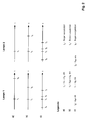
Figur 2 zeigt - am Beispiel zweier 70 W-Metallhalogenid-Entladungslampen mit unthorierten Elektroden und einem Zündgasdruck von ca. 130 hPa (Argon) - einen schematischen (nicht maßstäblichen) Vergleich der Dauern der Startphasen bei Anwendung zweier konventioneller Zündverfahren a, b sowie des erfindungsgemäßen Verfahrens c. Zu diesem Zweck sind u.a. jeweils die Zeitpunkte t₁, tS für das Einschalten der Betriebsspannung bzw. der vollständigen Ausbildung des Bogens - d.h. dem Ende der Übernahmephase - auf Zeitachsen t eingezeichnet. Die markierten Zeitpunkte wurden oszillographischen Aufnahmen des zeitlichen Verlaufs der jeweiligen Elektrodenspannung entnommen. Als Zeitpunkt tS wurde dabei jeweils der Spannungssprung auf die Bogenbrennspannung gewählt.Figure 2 shows - using the example of two 70 W metal halide discharge lamps with unthorated electrodes and an ignition gas pressure of approx. 130 hPa (argon) - a schematic (not to scale) comparison of the duration of the starting phases when using two conventional ignition methods a, b and the invention Procedure c. For this purpose, the
Der Fall a zeigt das Ergebnis bei Verwendung eines induktiven Vorschaltgeräts inklusive konventioneller Zündschaltung. Zum Zeitpunkt t₁ wurden die Netzspannung UB und eine bis zur Bogenübernahme andauernde Folge von Hochspannungspulsen U P an die Lampenelektroden gelegt. Nach ca. 2,7 s - symbolisiert durch die Zeitmarke tS - war der Bogen der Lampe 1 vollständig ausgebildet. Die Lampe 2 konnte hingegen nicht gezündet werden.Case a shows the result when using an inductive ballast including conventional ignition circuit. At the
Im Fall b wurde zum Zeitpunkt t₁ die Netzspannung UB und gleichzeitig (ΔtH = 0) eine hochfrequente Startspannung UHF an die Lampenelektroden gelegt. Die Zeitdauer tS - t₁ bis zum Ende der Übernahmephase betrug für die Lampe 1 ca. 0,9 s und für die Lampe 2 ca. 1,3 s. Während dieser Zeitdauer zeigten beide Lampen deutliche Flackererscheinungen.In case b, the line voltage U B and at the same time (Δt H = 0) a high-frequency starting voltage U HF was applied to the lamp electrodes at the
Im Fall c wurde die hochfrequente Spannung UHF zum Zeitpunkt t₀ < t₁, d.h. vor dem Zuschalten der Netzspannung UB an die Lampenelektroden gelegt. Auf diese Weise wurden die Elektroden während der Dauer ![]()
![]()
Dieser Vergleich belegt eindrucksvoll die vorteilhafte Wirkung der Erfindung.
Figur 3 zeigt ein Blockschaltbild einer prinzipiellen Schaltungsanordnung zur Durchführung des Verfahrens gemäß Figur 1. Sie besteht im wesentlichen aus einem die Betriebsspannung liefernden Betriebsgerät V, einem HF-Zündgerät Z zur Erzeugung der hochfrequenten Startspannung sowie aus zwei von einem Zeitgeber T gesteuerten und mit dem HF-Zünd- bzw. Betriebsgerät verbundenen Schaltern S1 bzw. S2. Sowohl das Betriebsgerät V als auch das HF-Zündgerät Z sind mit der Entladungslampe EL verbunden. Ein HF-Sperrglied SG zwischen Betriebsgerät V und Entladungslampe EL einerseits sowie Betriebsgerät V und HF-Zündgerät Z andererseits verhindert während der Überlappphase die Einkopplung der Startspannung in das Betriebsgerät V.FIG. 3 shows a block diagram of a basic circuit arrangement for carrying out the method according to FIG. 1. It essentially consists of an operating device V supplying the operating voltage, an HF ignition device Z for generating the high-frequency starting voltage and two controlled by a timer T and with the HF -Ignition or control gear connected switches S1 and S2. Both the operating device V and the HF ignition device Z are connected to the discharge lamp EL. An HF blocking element SG between control gear V and discharge lamp EL on the one hand and control gear V and HF ignition device Z on the other hand prevents the starting voltage from being coupled into control gear V during the overlap phase.
Figur 4 zeigt ein erweitertes Blockschaltbild einer Schaltungsanordnung gemäß Figur 3. Sie besteht aus einem mit 230 V und 50 Hz Netzspannung betriebenen konventionellen induktiven Vorschaltgerät V, einem HF-Leistungsoszillator HF nach an sich bekannten Schaltungsprinzipien, der eine hochfrequente Spannung erzeugt und mit dem nachgeschalteten Reihenresonanzkreis aus Spule L und Kondensator C3 ein HF-Überlagerungszündgerät bildet, sowie aus zwei mittels einer an sich bekannten Zeitgeberschaltung T, - hier realisiert durch Komparatoren mit durch RC-Glieder bestimmter Schaltverzögerung - gesteuerten Schaltern S1, S2.FIG. 4 shows an expanded block diagram of a circuit arrangement according to FIG. 3. It consists of a conventional inductive ballast V operated with 230 V and 50 Hz mains voltage, an HF power oscillator HF according to known circuit principles, which generate a high-frequency voltage and form an HF superimposed ignitor with the downstream series resonant circuit consisting of coil L and capacitor C3, as well as two by means of a timer circuit T, known per se - implemented here by comparators with switching delay determined by RC elements - controlled switches S1, S2.
Das Vorschaltgeräts V besteht aus einer seriellen Vorschaltdrossel Dr1 zur Begrenzung des Lampenstroms und einem parallel zum Eingang 1, 2 geschalteten Kompensationskondensator C1 zur Verbesserung des Leistungsfaktors. Die zwei Eingangsklemmen 1,2 des Vorschaltgeräts V sind mit der Netzspannung verbunden. Die Zeitgeberschaltung T ist vom Ausgang 3,4 des Betriebsgeräts V gespeist. Dazu ist die Zeitgeberschaltung T einerseits über eine Diode D mit der Vorschaltdrossel Dr1 und andererseits mit dem Fußpunkt des Kompensationskondensators C1 verbundenen. Der Eingang 5,6 des HF-Leistungsoszillators HF ist auf ähnliche Weise gespeist. Dazu ist eine erste Eingangsklemme 5 des HF-Leistungsoszillators HF mit dem Verbindungspunkt zwischen der Diode D und der Zeitgeberschaltung T kontaktiert. Die zweite Eingangsklemme 6 des HF-Leistungsoszillators HF ist über einen ersten Schalter S1, z.B. einen Halbleiterschalter, mit dem Fußpunkt des Kompensationskondensator C1 verbunden. Der Schalter S1 schaltet für die Dauer der Zünd- und Vorheiz- sowie der Überlappphase den HF-Leistungsoszillator HF ein. Der Verbindungspunkt zwischen der Vorschaltdrossel Dr1 und der Diode D ist über einen zweiten Schalter S2, beispielsweise ein mechanisches Relais sowie über eine Drossel Dr2 und eine Spule L mit einer ersten Elektrode der Entladungslampe EL verbunden. Die zweite Elektrode der Entladungslampe EL ist mit dem Fußpunkt des Kompensationskondensator C1 kontaktiert. Nach der Vorheizzeit verbindet somit der Schalter S2 das Betriebsgerät V mit der Entladungslampe EL. Der Kondensator C3 verbindet eine erste Ausgangsklemme 8 des HF-Leistungsoszillators mit der ersten Elektrode der Entladungslampe EL. Der Kondensator C3 bildet gemeinsam mit der Spule L einen Reihenresonanzkreis, der mittels Resonanzüberhöhung die zum Zünden der Lampenfüllung erforderliche Amplitude der hochfrequenten Startspannung an den Elektroden der Lampe EL bereitstellt. Die Drossel Dr2 wirkt als HF-Sperre zwischen dem Ausgang des HF-Leistungsoszillators HF und der Vorschaltdrossel Dr1 des Betriebsgeräts V. Der Verbindungspunkt zwischen der Drossel Dr2 und der Spule L ist über einen Koppelkondensator C2 mit der zweiten Ausgangsklemme 7 des HF-Leistungsoszillators verbunden. Er koppelt zum einen den HF-Strom in den Reihenresonanzkreis und trennt zum anderen die Netzspannung galvanisch vom HF-Teil.The ballast V consists of a series ballast choke Dr1 to limit the lamp current and a compensation capacitor C1 connected in parallel to the
Der Vorteil dieser Anordnung ist die Möglichkeit eines problemlosen Austausches konventioneller Zündgeräte durch das HF-Zündgerät inklusive der zugehörigen Schalter S1,S2 und des Zeitgebers T.The advantage of this arrangement is the possibility of a problem-free replacement of conventional ignition devices by the HF ignition device including the associated switches S1, S2 and the timer T.
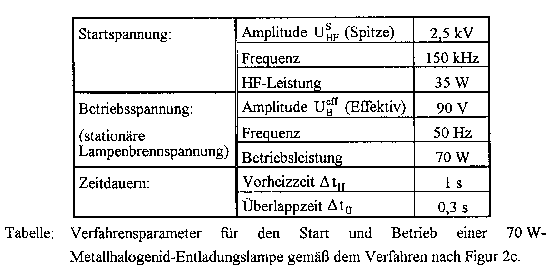
In Figur 5 ist ein Vergleich gemessener Lichtströme (Y1-Achse) als Funktion der kumulierten Anzahl von Zündungen (X-Achse) für Lampen mit HF-Zündgerät (Kurve 1) bzw. konventionellem Zündgerät (Kurve 2) dargestellt. Die kumulierte Anzahl wurde dabei in der Weise realisiert, daß die Lampen im Betrieb jede Stunde einmal aus- bzw. eingeschaltet wurden. Das bedeutet, daß hier die Anzahl der Schaltungen (Werte der X-Achse) der Betriebsdauer in Stunden entspricht. Die Y1-Koordinaten geben somit den Lichtstrom der Lampen in Kilolumen (klm) bei der bis zum Zeitpunkt der jeweiligen Lichtstrommessung ausgeführten Anzahl von Zündungen an. Die Messungen wurden an 70 W Metallhalogenid-Entladungslampen mit thorierten Elektroden aber ohne Kr85-Zusatz durchgeführt. Dabei waren im Falle des HF-Zündgeräts die in der Tabelle gezeigten Verfahrensparameter eingestellt. Deutlich ist zu erkennen, wie mit der Anzahl der ausgeführten Zündungen der Lichtstrom bei der erfindungsgemäßen Betriebsweise (Kurve 1) weniger abnimmt als bei der konventionellen Betriebsweise (Kurve 2). Besonders deutlich ist der Nutzen der Erfindung aus der Kurve 3 ersichtlich, welche den prozentualen Gewinn an Lichtstrom bei den erfindungsgemäß betriebenen Lampen bezüglich konventionell betriebenen Lampen zeigt. Dieser Gewinn nimmt im Rahmen der Messungen mit der Anzahl der Zündungen stetig zu und erreicht bei 1000 Zündungen bereits knapp 10 %.FIG. 5 shows a comparison of measured luminous fluxes (Y1 axis) as a function of the cumulative number of ignitions (X axis) for lamps with an HF igniter (curve 1) or a conventional igniter (curve 2). The cumulative number was realized in such a way that the lamps were switched on and off once every hour during operation. This means that the number of switching operations (values on the X axis) corresponds to the operating time in hours. The Y1 coordinates thus indicate the luminous flux of the lamps in kilolumens (klm) for the number of ignitions carried out up to the time of the respective luminous flux measurement. The measurements were carried out on 70 W metal halide discharge lamps with thoriated electrodes but without the addition of Kr85. In the case of the HF ignition device, the process parameters shown in the table were set. It can be clearly seen how the luminous flux decreases less with the number of ignitions carried out in the operating mode according to the invention (curve 1) than in the conventional operating mode (curve 2). The benefit of the invention can be seen particularly clearly from
Claims (20)
Applications Claiming Priority (2)
| Application Number | Priority Date | Filing Date | Title |
|---|---|---|---|
| DE4442898 | 1994-12-02 | ||
| DE4442898A DE4442898A1 (en) | 1994-12-02 | 1994-12-02 | Method and circuit arrangement for starting and operating high-pressure discharge lamps |
Publications (3)
| Publication Number | Publication Date |
|---|---|
| EP0715487A2 true EP0715487A2 (en) | 1996-06-05 |
| EP0715487A3 EP0715487A3 (en) | 1996-08-14 |
| EP0715487B1 EP0715487B1 (en) | 2002-02-20 |
Family
ID=6534709
Family Applications (1)
| Application Number | Title | Priority Date | Filing Date |
|---|---|---|---|
| EP95118397A Expired - Lifetime EP0715487B1 (en) | 1994-12-02 | 1995-11-22 | Process and circuit for starting and operating high pressure discharge lamps |
Country Status (4)
| Country | Link |
|---|---|
| US (1) | US5821696A (en) |
| EP (1) | EP0715487B1 (en) |
| JP (1) | JPH08227795A (en) |
| DE (2) | DE4442898A1 (en) |
Cited By (3)
| Publication number | Priority date | Publication date | Assignee | Title |
|---|---|---|---|---|
| EP1619936A2 (en) * | 2004-07-20 | 2006-01-25 | Patent -Treuhand-Gesellschaft für elektrische Glühlampen mbH | Circuit and method for operating a HID lamp |
| DE102008009144A1 (en) | 2008-02-14 | 2009-08-20 | Osram Gesellschaft mit beschränkter Haftung | Gas discharge ignition method for mercury free halogen-metal vapor- high pressure discharge lamp of motor vehicle headlight, involves producing alternating field with frequency equal/larger than twenty kilohertz in medium for ignition |
| US7825603B2 (en) | 2005-01-03 | 2010-11-02 | Koninklijke Philips Electronics N.V. | Lighting assembly and method of operating a discharge lamp |
Families Citing this family (6)
| Publication number | Priority date | Publication date | Assignee | Title |
|---|---|---|---|---|
| DE19909530A1 (en) * | 1999-03-04 | 2001-01-18 | Patent Treuhand Ges Fuer Elektrische Gluehlampen Mbh | Circuit arrangement for operating at least one high-pressure discharge lamp and operating method |
| US6194845B1 (en) * | 1999-11-03 | 2001-02-27 | Osram Sylvania Inc. | Ballasts with tapped inductor arrangements for igniting and powering high intensity discharge lamps |
| US6369522B1 (en) * | 2000-06-30 | 2002-04-09 | General Electric Company | Metal halide lamp lumen depreciation improvement |
| DE10036952A1 (en) * | 2000-07-28 | 2002-02-07 | Patent Treuhand Ges Fuer Elektrische Gluehlampen Mbh | Reduction of the terminal voltage of control gear for gas discharge lamps |
| DE10202645A1 (en) * | 2002-01-23 | 2003-07-31 | Philips Intellectual Property | Method and device for controlling a gas discharge lamp and lighting system with a gas discharge lamp and control device |
| JP2007533072A (en) * | 2004-04-09 | 2007-11-15 | コーニンクレッカ フィリップス エレクトロニクス エヌ ヴィ | High pressure sodium lamp |
Citations (2)
| Publication number | Priority date | Publication date | Assignee | Title |
|---|---|---|---|---|
| US4331905A (en) | 1980-10-27 | 1982-05-25 | General Electric Company | Starting and operating circuit for gaseous discharge lamps |
| DE4227427A1 (en) | 1992-08-19 | 1994-02-24 | Kres Ekkehard Dipl Inform Fh | Ignition procedure for DC high-pressure gas-discharge lamps - uses inductor and capacitor to store energy from main power supply which is coupled inductively to ballast circuit |
Family Cites Families (8)
| Publication number | Priority date | Publication date | Assignee | Title |
|---|---|---|---|---|
| FR2034104A1 (en) * | 1969-02-04 | 1970-12-11 | Hoste Marcel | |
| DE2909605A1 (en) * | 1979-03-12 | 1980-09-25 | Patra Patent Treuhand | CONTROL UNIT FOR OPERATING A DISCHARGE LAMP |
| JPS6016080B2 (en) * | 1980-08-20 | 1985-04-23 | ウシオ電機株式会社 | DC discharge lamp lighting device |
| US4378514A (en) * | 1980-10-27 | 1983-03-29 | General Electric Company | Starting and operating circuit for gaseous discharge lamps |
| GB2172451B (en) * | 1985-02-07 | 1989-06-14 | El Co Villamos Keszulekek Es S | Circuit system for igniting and lighting a high-pressure discharge lamp particulary a sodium vapour lamp |
| EP0411617A3 (en) * | 1989-08-01 | 1992-05-13 | Toshiba Lighting & Technology Corporation | Method of lighting discharge lamp and discharge lamp lighting apparatus |
| US5036256A (en) * | 1990-06-21 | 1991-07-30 | Gte Products Corporation | Arc discharge ballast suitable for automotive applications |
| US5262699A (en) * | 1991-08-26 | 1993-11-16 | Gte Products Corporation | Starting and operating circuit for arc discharge lamp |
-
1994
- 1994-12-02 DE DE4442898A patent/DE4442898A1/en not_active Withdrawn
-
1995
- 1995-11-22 DE DE59510062T patent/DE59510062D1/en not_active Expired - Lifetime
- 1995-11-22 EP EP95118397A patent/EP0715487B1/en not_active Expired - Lifetime
- 1995-11-30 US US08/565,077 patent/US5821696A/en not_active Expired - Fee Related
- 1995-12-04 JP JP7315287A patent/JPH08227795A/en active Pending
Patent Citations (2)
| Publication number | Priority date | Publication date | Assignee | Title |
|---|---|---|---|---|
| US4331905A (en) | 1980-10-27 | 1982-05-25 | General Electric Company | Starting and operating circuit for gaseous discharge lamps |
| DE4227427A1 (en) | 1992-08-19 | 1994-02-24 | Kres Ekkehard Dipl Inform Fh | Ignition procedure for DC high-pressure gas-discharge lamps - uses inductor and capacitor to store energy from main power supply which is coupled inductively to ballast circuit |
Cited By (4)
| Publication number | Priority date | Publication date | Assignee | Title |
|---|---|---|---|---|
| EP1619936A2 (en) * | 2004-07-20 | 2006-01-25 | Patent -Treuhand-Gesellschaft für elektrische Glühlampen mbH | Circuit and method for operating a HID lamp |
| EP1619936A3 (en) * | 2004-07-20 | 2011-01-26 | Patent -Treuhand-Gesellschaft für elektrische Glühlampen mbH | Circuit and method for operating a HID lamp |
| US7825603B2 (en) | 2005-01-03 | 2010-11-02 | Koninklijke Philips Electronics N.V. | Lighting assembly and method of operating a discharge lamp |
| DE102008009144A1 (en) | 2008-02-14 | 2009-08-20 | Osram Gesellschaft mit beschränkter Haftung | Gas discharge ignition method for mercury free halogen-metal vapor- high pressure discharge lamp of motor vehicle headlight, involves producing alternating field with frequency equal/larger than twenty kilohertz in medium for ignition |
Also Published As
| Publication number | Publication date |
|---|---|
| US5821696A (en) | 1998-10-13 |
| DE4442898A1 (en) | 1996-06-05 |
| EP0715487B1 (en) | 2002-02-20 |
| JPH08227795A (en) | 1996-09-03 |
| DE59510062D1 (en) | 2002-03-28 |
| EP0715487A3 (en) | 1996-08-14 |
Similar Documents
| Publication | Publication Date | Title |
|---|---|---|
| EP0868833B1 (en) | High-pressure discharge lamp with an auxiliary ignition electrode as well as circuitry and process for operation | |
| DE69913621T2 (en) | Electronic ballast | |
| DE2905923A1 (en) | COMBINED DISCHARGE AND LIGHT BULB WITH THERMAL SWITCH CONTROL | |
| EP0715487B1 (en) | Process and circuit for starting and operating high pressure discharge lamps | |
| DE10138936A1 (en) | Switch-on device for a gas discharge lamp | |
| EP1659835B1 (en) | High pressure discharge lamp with impulse starter and operational method for a high pressure lamp | |
| DE3015451A1 (en) | METAL STEAM DISCHARGE LAMP | |
| EP1829432A2 (en) | Circuit arrangement for a starting unit of a discharge lamp | |
| EP0111373B1 (en) | Circuit arrangement for starting and operating high pressure gas discharge lamps | |
| DE19829600A1 (en) | Procedure and ballast for driving high pressure AC discharge lamps | |
| EP1124406B1 (en) | Method of operating a dielectric barrier discharge lamp | |
| DE3813030A1 (en) | QUICKLY REPEATABLE METAL HALOGEN LAMP AND METHOD FOR OPERATING THE LAMP | |
| DE69930897T2 (en) | Arrangement for operating a discharge lamp | |
| EP0189122B1 (en) | Metal vapor lamp starting and operating apparatus | |
| DE2718151A1 (en) | PULSE CIRCUIT FOR GAS DISCHARGE LAMPS | |
| WO1999050878A2 (en) | Method for generating a pulsed electron beam and a trigger plasma source for carrying out said method | |
| EP1869952A1 (en) | Starter auxiliary electrode starting device with an arc gap | |
| DE19956391A1 (en) | Starting and operating fluorescent lamp involves measuring cathode temperature when cathode current is flowing and igniting discharge when certain temperature is reached | |
| DE102005035745A1 (en) | Discharge lamp e.g. video and projection lamp, igniting device, has coupling unit inductively coupling primary voltage pulse in ignition circuit and including voltage transmission ratio that is selected from certain range | |
| DE2602604C2 (en) | Circuit arrangement for igniting and operating a gas discharge lamp | |
| DE60003145T2 (en) | Electronic ballast for neon tubes | |
| SU945918A1 (en) | Method of treatment of unsealed cathode-ray tubes with gas-containing gas absorber | |
| KR830002174B1 (en) | Apparatus for operation a discharge lamp | |
| WO2004054327A1 (en) | Electric circuit for igniting a discharge lamp and method for igniting the discharge lamp | |
| US2694787A (en) | Starting circuit for electric lamps |
Legal Events
| Date | Code | Title | Description |
|---|---|---|---|
| PUAI | Public reference made under article 153(3) epc to a published international application that has entered the european phase |
Free format text: ORIGINAL CODE: 0009012 |
|
| AK | Designated contracting states |
Kind code of ref document: A2 Designated state(s): BE DE FR GB IT NL |
|
| PUAL | Search report despatched |
Free format text: ORIGINAL CODE: 0009013 |
|
| AK | Designated contracting states |
Kind code of ref document: A3 Designated state(s): BE DE FR GB IT NL |
|
| 17P | Request for examination filed |
Effective date: 19960904 |
|
| 17Q | First examination report despatched |
Effective date: 19990819 |
|
| GRAG | Despatch of communication of intention to grant |
Free format text: ORIGINAL CODE: EPIDOS AGRA |
|
| GRAG | Despatch of communication of intention to grant |
Free format text: ORIGINAL CODE: EPIDOS AGRA |
|
| GRAH | Despatch of communication of intention to grant a patent |
Free format text: ORIGINAL CODE: EPIDOS IGRA |
|
| GRAH | Despatch of communication of intention to grant a patent |
Free format text: ORIGINAL CODE: EPIDOS IGRA |
|
| RIC1 | Information provided on ipc code assigned before grant |
Free format text: 7H 05B 41/288 A, 7H 05B 41/04 B, 7H 05B 41/38 B |
|
| REG | Reference to a national code |
Ref country code: GB Ref legal event code: IF02 |
|
| GRAA | (expected) grant |
Free format text: ORIGINAL CODE: 0009210 |
|
| AK | Designated contracting states |
Kind code of ref document: B1 Designated state(s): BE DE FR GB IT NL |
|
| REF | Corresponds to: |
Ref document number: 59510062 Country of ref document: DE Date of ref document: 20020328 |
|
| GBT | Gb: translation of ep patent filed (gb section 77(6)(a)/1977) |
Effective date: 20020429 |
|
| ET | Fr: translation filed | ||
| PLBE | No opposition filed within time limit |
Free format text: ORIGINAL CODE: 0009261 |
|
| STAA | Information on the status of an ep patent application or granted ep patent |
Free format text: STATUS: NO OPPOSITION FILED WITHIN TIME LIMIT |
|
| 26N | No opposition filed |
Effective date: 20021121 |
|
| PGFP | Annual fee paid to national office [announced via postgrant information from national office to epo] |
Ref country code: GB Payment date: 20051108 Year of fee payment: 11 |
|
| PGFP | Annual fee paid to national office [announced via postgrant information from national office to epo] |
Ref country code: NL Payment date: 20051109 Year of fee payment: 11 |
|
| PGFP | Annual fee paid to national office [announced via postgrant information from national office to epo] |
Ref country code: BE Payment date: 20051118 Year of fee payment: 11 |
|
| PGFP | Annual fee paid to national office [announced via postgrant information from national office to epo] |
Ref country code: FR Payment date: 20051122 Year of fee payment: 11 |
|
| PG25 | Lapsed in a contracting state [announced via postgrant information from national office to epo] |
Ref country code: BE Free format text: LAPSE BECAUSE OF NON-PAYMENT OF DUE FEES Effective date: 20061130 |
|
| PGFP | Annual fee paid to national office [announced via postgrant information from national office to epo] |
Ref country code: IT Payment date: 20061130 Year of fee payment: 12 |
|
| PG25 | Lapsed in a contracting state [announced via postgrant information from national office to epo] |
Ref country code: NL Free format text: LAPSE BECAUSE OF NON-PAYMENT OF DUE FEES Effective date: 20070601 |
|
| GBPC | Gb: european patent ceased through non-payment of renewal fee |
Effective date: 20061122 |
|
| NLV4 | Nl: lapsed or anulled due to non-payment of the annual fee |
Effective date: 20070601 |
|
| REG | Reference to a national code |
Ref country code: FR Ref legal event code: ST Effective date: 20070731 |
|
| PG25 | Lapsed in a contracting state [announced via postgrant information from national office to epo] |
Ref country code: GB Free format text: LAPSE BECAUSE OF NON-PAYMENT OF DUE FEES Effective date: 20061122 |
|
| BERE | Be: lapsed |
Owner name: *PATENT-TREUHAND-G.- FUR ELEKTRISCHE GLUHLAMPEN M. Effective date: 20061130 |
|
| PG25 | Lapsed in a contracting state [announced via postgrant information from national office to epo] |
Ref country code: FR Free format text: LAPSE BECAUSE OF NON-PAYMENT OF DUE FEES Effective date: 20061130 |
|
| PG25 | Lapsed in a contracting state [announced via postgrant information from national office to epo] |
Ref country code: IT Free format text: LAPSE BECAUSE OF NON-PAYMENT OF DUE FEES Effective date: 20071122 |
|
| PGFP | Annual fee paid to national office [announced via postgrant information from national office to epo] |
Ref country code: DE Payment date: 20110121 Year of fee payment: 16 |
|
| REG | Reference to a national code |
Ref country code: DE Ref legal event code: R119 Ref document number: 59510062 Country of ref document: DE Effective date: 20120601 |
|
| PG25 | Lapsed in a contracting state [announced via postgrant information from national office to epo] |
Ref country code: DE Free format text: LAPSE BECAUSE OF NON-PAYMENT OF DUE FEES Effective date: 20120601 |