EP0715465B1 - Procédé de détection de connexions de type Péritel dans un réseau domestique - Google Patents
Procédé de détection de connexions de type Péritel dans un réseau domestique Download PDFInfo
- Publication number
- EP0715465B1 EP0715465B1 EP95402460A EP95402460A EP0715465B1 EP 0715465 B1 EP0715465 B1 EP 0715465B1 EP 95402460 A EP95402460 A EP 95402460A EP 95402460 A EP95402460 A EP 95402460A EP 0715465 B1 EP0715465 B1 EP 0715465B1
- Authority
- EP
- European Patent Office
- Prior art keywords
- video
- network
- sources
- connections
- group
- Prior art date
- Legal status (The legal status is an assumption and is not a legal conclusion. Google has not performed a legal analysis and makes no representation as to the accuracy of the status listed.)
- Expired - Lifetime
Links
- 238000000034 method Methods 0.000 title claims description 38
- 238000001514 detection method Methods 0.000 title description 5
- 230000008569 process Effects 0.000 claims description 25
- 230000005540 biological transmission Effects 0.000 claims description 15
- 238000000926 separation method Methods 0.000 claims description 2
- 238000011144 upstream manufacturing Methods 0.000 description 4
- 230000008901 benefit Effects 0.000 description 2
- 238000010586 diagram Methods 0.000 description 2
- 230000006870 function Effects 0.000 description 2
- 238000012545 processing Methods 0.000 description 2
- 230000004044 response Effects 0.000 description 2
- 238000012552 review Methods 0.000 description 2
- 230000004913 activation Effects 0.000 description 1
- 238000012550 audit Methods 0.000 description 1
- 238000012937 correction Methods 0.000 description 1
- 230000001939 inductive effect Effects 0.000 description 1
- 230000002452 interceptive effect Effects 0.000 description 1
- 238000007726 management method Methods 0.000 description 1
- 238000012544 monitoring process Methods 0.000 description 1
- 210000000056 organ Anatomy 0.000 description 1
- 230000008520 organization Effects 0.000 description 1
- 238000001228 spectrum Methods 0.000 description 1
Images
Classifications
-
- H—ELECTRICITY
- H04—ELECTRIC COMMUNICATION TECHNIQUE
- H04N—PICTORIAL COMMUNICATION, e.g. TELEVISION
- H04N5/00—Details of television systems
- H04N5/76—Television signal recording
- H04N5/765—Interface circuits between an apparatus for recording and another apparatus
- H04N5/775—Interface circuits between an apparatus for recording and another apparatus between a recording apparatus and a television receiver
-
- H—ELECTRICITY
- H04—ELECTRIC COMMUNICATION TECHNIQUE
- H04N—PICTORIAL COMMUNICATION, e.g. TELEVISION
- H04N7/00—Television systems
- H04N7/10—Adaptations for transmission by electrical cable
Definitions
- the invention relates to a connection detection method. Scart type between different devices in a home automation network.
- the invention applies in the field of home automation.
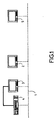
- FIG. 1 illustrates the problem.
- a home automation bus 1 connects different devices or organs, such as televisions 2 and 3 and a VCR 4.
- TV 3 and VCR 4 are on the other hand connected by a SCART socket (or "SCART" socket for Syndicate of Manufacturers of Radio Receivers and Television).
- SCART socket or "SCART" socket for Syndicate of Manufacturers of Radio Receivers and Television.
- the catch Scart is described in European standard EN 50 049.
- a video signal distribution network is described in document EP-A-0 409 702.
- the home automation network also includes a central control 5.
- This control unit can control certain functions of devices connected to the network. Connection by the Scart link is not necessarily directly controllable by this central unit.
- Some devices react when they are in "Standby" mode, the presence of a signal on certain pins of the SCART sockets to which they are connected. They are for example pin 8.
- TV 3 can detect the presence of a program coming from of VCR 4 by monitoring the state of this pin. When this pin has an active signal, TV 3 switches on automatically in "On” mode and selects the active Scart socket as source video. This automatic detection allows, among other things, not to manipulate than the VCR to view a cassette. Just turn it on VCR and play the tape: the TV turns on automatically to allow viewing.
- the video signals from a video source such as VCR 4 are viewed on a TV other than TV 3.
- Signals video are then transmitted through a network channel to a video unit viewing such as TV 2, located for example in another room as devices 3 and 4. This transmission is controlled by the unit central 5.
- the physical transmission medium is for example consisting of coaxial cables and / or radio frequency links.
- Scart type connection means a connection between at least two devices that cause the operation of at least one of said devices said receiver when transmitting a signal by a said devices said source on said connection.
- said method is implemented works when installing a new video source or a new video receiver in the network.
- said method it is put implemented on the initiative of a user.
- the memorization of connections is used to disable video receivers set undesired operation upon start-up from a video source for which there are such connections.
- This division into groups of video sources makes it possible to process a large number of sources at the same time, which is particularly desirable when the network has few connections of Scart type.
- said limit number being strictly greater than 1
- the process conforms to one of the points is used to detect said connections, said set containing said limit number of video sources being considered as constituting all the video sources of the network for the application of said process.
- step h comprising a step of memorizing the existence of a connection between said video source of said set and said video receivers turned on.
- the pyramidal process is continued until sets are reduced to a single source video.
- the identification of a connection is then immediate.
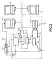
- FIG 2 shows some elements in more detail of the home automation network in Figure 1.
- Transmission bus 1 connects devices 2, 3 and 4.
- the dotted frame 6 represents the interface between bus 1 and video recorder 4. To keep the diagrams clear, only one interface has been shown. It is quite obvious that similar interfaces are used to connect the other devices of the network.
- the network illustrated is a network in accordance with the "Home Systems Specification” specification published by the European Home Systems Association (EHSA), March 15/24, 1992.
- EHSA European Home Systems Association
- the bus 1 is constituted by a double coaxial cable as specified in the "Home" section Systems Specification Coaxial Cable “from EHSA.
- EHSA Electronic Health Services Organization
- downstream data respectively representing the broadband input stream and the broadband output stream of one of the illustrated devices.
- Spectrum wide band goes from 0 Hz to 860 MHz, the DC component being reserved for a DC supply of 15 volts, the band frequency up to 1 MHz being reserved for the transmission of data from service (“Datagrams”), while the band going from 40 MHz to 860 MHz is reserved for the transmission of large-scale video and data signals debit.
- the upstream and downstream flows are symbolized in Figure 2 by line 7 and line 8 respectively.
- the upstream flow is filtered by a baseband filter 9, to extract transmitted service data to a microprocessor 10.
- the latter is connected to a random access memory 11 and to a read only memory 12.
- the random access memory 11 allows the microprocessor to store information from other devices on the network, in particular orders from a central unit 5.
- the microprocessor is also connected to a read only memory 12, which contains among other routines for analysis and processing of service data.
- the microprocessor controls appropriately the functions of the video recorder.
- the filter 9 is also connected to a DC power supply 13.
- the upstream flow is transmitted to an allocation unit of channels 14.
- This unit is connected to VCR 4 as well both in and out. In particular, it transposes the tape basic - transmission channel and vice versa.
- the outgoing signal from unit 14 is combined with the service data from the filter 9 at an amplifier summator 15, thus providing the downstream flow.
- the central unit is integrated in a television receiver, but it can be integrated in another type of device or be connected independently to the network.
- the screen of this receiver is used to display menus interactive allowing the user to act on the functioning of the network.
- the central unit also has a list of devices connected to the network. This list is updated regularly to keep account of newly connected or disconnected devices.
- the registration and address assignment procedure of a device is described in more detail in the section "Network Management" of the EHSA document whose reference has already been given. Such a procedure is not the subject of this request.
- the type of network devices is identified by a descriptor.
- video sources we can cite: a video recorder in as source (descriptor 2502), video modulator, camera video (3D01) ...
- a video printer (0501), a video recorder as a recorder (2501), a video tuner ...
- the interface between the VCR 4 and bus 1 is shown to be external to the for the sake of clarity. It is obvious that this interface can be integrated into the VCR or another device, which has the particular advantage of allowing the use of internal VCR circuits, such as a microprocessor or microcontroller.
- the connector 8 of this socket carries a DC voltage of 12V.
- FIG. 3 shows a flowchart of the example particular of the process according to the invention.
- the central unit puts in standby mode all video sources, as well as all video receivers.
- each source will be treated independently.
- Unity control unit switches on the first video source, then activates transmitting a video signal from this source.
- this source is a video recorder which we will assume is provided with a cassette.
- VCR modulator we can also implement a any built-in VCR modulator to provide a signal video.
- the central unit then reviews the state of all of the video receivers. If a receiver is on, then a SCART connection exists between this receiver and the video source.
- the video source as well as any activated receivers, are then respectively deactivated or put on standby. The process is resumed for the next video source.
- the notation taken for the organization chart numbers the sources of 1 to imax and the receivers from 1 to jmax. If one of the two imax values or jmax is zero, the algorithm is not implemented, no connection of the type sought not existing in the network.
- the network illustrated in FIG. 2 gives rise to the exchange of commands below during the application of the process according to this example. It is assumed that the video recorder 4 is the only video source on the network, the receivers being televisions 2 and 3. The video recorder 4 can also be considered as a receiver. However, being the only source, its state will not be tested in this example.
- the central unit 5 is named UC, the televisions 2 and 3 respectively TV1 and TV2 and the VCR VCR.
- UC deduces that there is no SCART connection between VCR and TV1 UC TV2 POWER, read-request Reading of TV2 status by CPU TV2 UC POWER, read-response, ON TV2 reviews its status to UC, which deduces the existence of a SCART connection between VCR and TV2 UC TV2 POWER, write, standby Return TV2 to standby mode UC VCR POWER, write, standby Return VCR to standby mode
- the central unit has a complete map of SCART connections in the network. it is indeed obviously Scart connections inducing an ignition of a device.
- the central unit uses a given source, it can well send adequate orders to devices connected to this source.
- the method according to the invention is implemented when installing a new source video or a new receiver in the network.
- the process is not put only when the type of device is such that it can possibly induce a new SCART socket connection.
- the method is implemented on user initiative.
- all of the sources video is divided into several groups. Instead of lighting just one source at a time, an entire group of sources is switched on same time. If no receiver is switched on, no SCART connection exists for this group of sources. If at least one receiver is on, the sources in this group are treated independently to determine existing connections. This variant allows more processing quickly a large number of devices.
- a pyramid search Scart type connections are made. At first, all video sources on the network are enabled. If no receiver is not lit, then no connection is detected. In the case video sources are divided into at least two groups of sources. For each group of sources, the same operation is restarted: activation of all of the group's sources, then possible separation into subgroups. This division can be continued to the level of individual sources, or stop when a group contains a limit number of sources, which will be processed one to one.
- the user can do know connections directly to the central unit.
- the process in accordance with the invention is then used to check the validity of the data thus entered and make a possible correction.
Landscapes
- Engineering & Computer Science (AREA)
- Multimedia (AREA)
- Signal Processing (AREA)
- Two-Way Televisions, Distribution Of Moving Picture Or The Like (AREA)
- Small-Scale Networks (AREA)
Description
- la figure 1, déjà décrite, représente schématiquement un réseau domotique,
- la figure 2 représente schématiquement un réseau domotique de manière plus détaillée,
- la figure 3 représente un organigramme du procédé conforme à l'invention.
- allumer ou éteindre/mettre en veille un appareil
- activer une source d'émission vidéo.
| De | A | Commandes | Commentaires |
| UC | TV1 | POWER, write, standby | Mise en veille de TV1 |
| UC | TV2 | POWER, write, standby | Mise en veille de TV2 |
| UC | VCR | POWER, write, standby | Mise en veille du VCR |
| UC | VCR | MODE, write, play | VCR est allumé et mis en mode reproduction |
| UC | TV1 | POWER, read-request | Lecture de l'état de TV1 par UC |
| TV1 | UC | POWER, read-response, stanby | TV1 renvoie son état à UC. UC en déduit qu'il n'y a pas de connexion Péritel entre VCR et TV1 |
| UC | TV2 | POWER, read-request | Lecture de l'état de TV2 par UC |
| TV2 | UC | POWER, read-response, ON | TV2 revoie son état à UC, qui en déduit l'existence d'une connexion Péritel ents VCR et TV2 |
| UC | TV2 | POWER, write, standby | Remettre TV2 en mode veille |
| UC | VCR | POWER, write, standby | Remettre VCR en mode veille |
Claims (8)
- Procédé de détection de connexions de type Péritel dans un réseau domotique caractérisé en ce qu'il comporte les étapes:a) de désactiver les sources vidéo reliées au réseau,b) de mettre en veille les récepteurs vidéo reliés au réseau,c) de commander l'émission d'un signal vidéo d'une première source vidéo,d) de détecter les récepteurs vidéo allumés,e) de mémoriser l'existence d'une connexion entre ladite première source et lesdits récepteurs vidéo allumés,f) de désactiver ladite première source et de remettre en veille lesdits récepteurs vidéo allumés,g) de reprendre le procédé à partir de l'étape c avec chacune des sources restantes.
- Procédé selon la revendication 1, caractérisé en ce qu'il est mis en oeuvre lors de l'installation d'une nouvelle source vidéo ou d'un nouveau récepteur vidéo dans le réseau.
- Procédé selon l'une des revendications précédentes, caractérisé en ce qu'il est mis en oeuvre sur l'initiative d'un utilisateur.
- Procédé selon l'une des revendications précédentes, caractérisé en ce que la mémorisation des connexions est utilisée pour mettre en veille des récepteurs vidéo mis en fonctionnement de façon indésirable lors de la mise en fonctionnement d'une source vidéo pour laquelle il existe de telles connexions.
- Procédé de détection de connexions de type Péritel dans un réseau domotique caractérisé en ce qu'il comporte les étapes:a) de désactiver les sources vidéo reliées au réseau,b) de mettre en veille les récepteurs vidéo reliés au réseau,c) de commander l'émission d'un signal vidéo d'un groupe de sources vidéo,d) de détecter si aucun récepteur vidéo n'est allumé, et dans ce cas, de désactiver les sources vidéo dudit groupe et de reprendre l'étape c avec le groupe suivant de sources vidéo,e) dans le cas où au moins un récepteur vidéo allumé est détecté, de détecter les connexions pour ce groupe de sources vidéo selon le procédé conforme à l'une des revendications précédentes, ledit groupe étant considéré comme constituant l'ensemble des sources vidéo du réseau pour l'application dudit procédé,f) de reprendre l'étape c avec le groupe suivant de sources vidéo.
- Procédé de détection de connexions de type Péritel dans un réseau domotique caractérisé en ce qu'il comporte les étapes:a) de mettre en veille les récepteurs vidéo reliés au réseau,b) de commander l'émission de signaux vidéo à partir de toutes les sources vidéo du réseauc) de détecter si des récepteurs vidéo sont allumés,d) dans la négative, de conclure à l'inexistence desdites connexions,e) dans l'affirmative, de répartir les sources vidéo du réseau en au moins deux groupes, et de procéder aux étapes suivantes:f) de mettre en veille les récepteurs vidéo reliés au réseau,g) pour chaque groupe, de commander l'émission d'un signal vidéo à partir des sources dudit groupe,h) de détecter si des récepteurs vidéo sont allumés,i) dans la négative, de conclure à l'inexistence desdites connexions,j) dans l'affirmative, de procéder à une séparation en sous-groupes desdites sources appartenant audit groupe,k) de reprendre les étapes f à j pour chaque groupe, sous-groupe ou ensemble plus petit jusqu'à ce que les ensembles formés contiennent un nombre limite de sources vidéo.
- Procédé selon la revendication 6, caractérisé en ce que ledit nombre limite étant strictement supérieur à 1, le procédé conforme à l'une des revendications 1 à 4 est mis en oeuvre pour identifier lesdites connexions, ledit ensemble contenant ledit nombre limite de sources vidéo étant considéré comme constituant l'ensemble des sources vidéo du réseau pour l'application dudit procédé.
- Procédé selon la revendication 6, caractérisé en ce que ledit nombre limite étant de un, l'étape h comportant une étape de mémorisation de l'existence d'une connexion entre ladite source vidéo dudit ensemble et lesdits récepteurs vidéo allumés.
Applications Claiming Priority (3)
| Application Number | Priority Date | Filing Date | Title |
|---|---|---|---|
| FR9413236 | 1994-11-04 | ||
| FR9413236A FR2726720B1 (fr) | 1994-11-04 | 1994-11-04 | Procede de detection de connexions de type peritel dans un reseau domotique |
| US08/549,154 US5915206A (en) | 1994-11-04 | 1995-10-27 | Procedure for the detection of SCART type connections in a home systems network |
Publications (2)
| Publication Number | Publication Date |
|---|---|
| EP0715465A1 EP0715465A1 (fr) | 1996-06-05 |
| EP0715465B1 true EP0715465B1 (fr) | 1999-09-15 |
Family
ID=26231510
Family Applications (1)
| Application Number | Title | Priority Date | Filing Date |
|---|---|---|---|
| EP95402460A Expired - Lifetime EP0715465B1 (fr) | 1994-11-04 | 1995-11-03 | Procédé de détection de connexions de type Péritel dans un réseau domestique |
Country Status (4)
| Country | Link |
|---|---|
| US (1) | US5915206A (fr) |
| EP (1) | EP0715465B1 (fr) |
| JP (1) | JPH08237276A (fr) |
| FR (1) | FR2726720B1 (fr) |
Families Citing this family (15)
| Publication number | Priority date | Publication date | Assignee | Title |
|---|---|---|---|---|
| JP3658896B2 (ja) * | 1996-11-26 | 2005-06-08 | ソニー株式会社 | 情報信号伝送システム、再生装置及び表示装置 |
| GB9908291D0 (en) * | 1999-04-13 | 1999-06-02 | Pace Micro Tech Ltd | Power loopthrough |
| FI107493B (fi) * | 1999-06-07 | 2001-08-15 | Nokia Mobile Phones Ltd | Tiedonsiirtosovitin ja menetelmä tiedon siirtämiseksi |
| US6690657B1 (en) | 2000-02-25 | 2004-02-10 | Berkeley Concept Research Corporation | Multichannel distributed wireless repeater network |
| FR2802751B1 (fr) * | 1999-12-16 | 2002-02-08 | Sagem | Dispositif de mise en veille d'un repeteur radiofrequence |
| KR100475447B1 (ko) * | 2002-01-21 | 2005-03-10 | 엘지전자 주식회사 | 셋탑 박스를 가진 영상표시기기의 입력신호 처리방법 및장치 |
| KR100441602B1 (ko) * | 2002-04-11 | 2004-07-23 | 삼성전자주식회사 | 복수의 재생장치를 갖는 복합장치 및 그의 동작제어방법 |
| GB0210488D0 (en) * | 2002-05-08 | 2002-06-12 | Koninkl Philips Electronics Nv | Control of an AV content source component |
| GB0223003D0 (en) * | 2002-10-04 | 2002-11-13 | Pace Micro Tech Plc | Broadcast data reciever |
| FR2849324B1 (fr) * | 2003-01-21 | 2011-11-18 | Lg Electronics Inc | Procede et appareil de traitement de signaux d'entree de dispositif d'affichage |
| KR100602206B1 (ko) * | 2004-06-18 | 2006-07-19 | 삼성전자주식회사 | Scart 커넥터를 구비한 복합장치 및 그 제어 방법 |
| BRPI0608994A2 (pt) * | 2005-04-15 | 2010-01-12 | Thomson Licensing | decodificador de televisão digital de alta definição e de definição simples |
| EP1843576A3 (fr) * | 2006-04-04 | 2011-01-26 | Grundig Multimedia B.V. | Interface pour appareils électroniques de divertissement |
| CN102017623B (zh) * | 2007-08-01 | 2013-07-31 | 夏普株式会社 | 网络av设备和av网络系统 |
| BE1020459A3 (nl) * | 2012-01-16 | 2013-10-01 | Hoste Philip | Een schakelbaar stopcontact bediend door een settopbox, dat de stroomtoevoer naar het televisietoestel aan-of uitschakelt. |
Family Cites Families (7)
| Publication number | Priority date | Publication date | Assignee | Title |
|---|---|---|---|---|
| US4947244A (en) * | 1989-05-03 | 1990-08-07 | On Command Video Corporation | Video selection and distribution system |
| FR2649846A1 (fr) * | 1989-07-17 | 1991-01-18 | Monier Ste Civile | Reseau de distribution par commutation de signaux video avec modules individuels d'amplification, de selection et de reception de la telecommande |
| FR2670640A1 (fr) * | 1990-12-14 | 1992-06-19 | France Etat | Reseau domotique large bande cable multipoints, reconfigurable de distribution simultanee et/ou alternative de plusieurs types de signaux, et procede de transmission d'ordres de gestion du reseau. |
| GB9121203D0 (en) * | 1991-10-04 | 1991-11-20 | D2B Systems Co Ltd | Local communication bus system and apparatus for use in such a system |
| TW213530B (en) * | 1992-04-08 | 1993-09-21 | Philips Nv | Apparatus for use in an interconnection system |
| ATE156322T1 (de) * | 1992-09-14 | 1997-08-15 | Thomson Multimedia Sa | Verfahren und dekodieren zur auswertung zugriffssteuerungsbezogener daten |
| DE4425526C2 (de) * | 1993-07-27 | 2001-02-15 | Samsung Electronics Co Ltd | Videorekorder mit einem Anschluß für einen Gebührenfernsehdecodierer |
-
1994
- 1994-11-04 FR FR9413236A patent/FR2726720B1/fr not_active Expired - Fee Related
-
1995
- 1995-10-27 US US08/549,154 patent/US5915206A/en not_active Expired - Fee Related
- 1995-11-02 JP JP7286200A patent/JPH08237276A/ja not_active Ceased
- 1995-11-03 EP EP95402460A patent/EP0715465B1/fr not_active Expired - Lifetime
Also Published As
| Publication number | Publication date |
|---|---|
| JPH08237276A (ja) | 1996-09-13 |
| US5915206A (en) | 1999-06-22 |
| FR2726720B1 (fr) | 1997-01-03 |
| EP0715465A1 (fr) | 1996-06-05 |
| FR2726720A1 (fr) | 1996-05-10 |
Similar Documents
| Publication | Publication Date | Title |
|---|---|---|
| EP0715465A1 (fr) | Procédé de détection de connexions de type Péritel dans un réseau domestique | |
| EP0469963B1 (fr) | Dispositif de distribution de signaux vidéo et/ou audio entre plusieurs récepteurs | |
| EP0015797B1 (fr) | Système d'interconnexion sélective variable audio-vidéo | |
| US20090245747A1 (en) | Tv screen capture | |
| FR2770727A1 (fr) | Convertisseur de signaux base sur un ordinateur personnel, pour des services de television | |
| EP0696402A1 (fr) | Procede de programmation automatique de tuner et dispositif de mise en uvre | |
| FR2874472A1 (fr) | Procede, article de fabrication et dispositif destines a mettre a jour un logiciel dans un dispositif individuel | |
| KR20060123142A (ko) | 시간-쉬프트된 방송 콘텐트에의 광고 삽입 | |
| EP1579691A1 (fr) | Procede pour etablir une liste de contenus dans un appareil connect un r seau domesti que et appareil associe au proce de | |
| FR2579397A2 (fr) | Procede et dispositif d'acquisition, de memorisation et de transmission de donnees specialisees relatives notamment a l'enregistrement des emissions, entre un appareil de type magnetoscope et un centre de traitement | |
| US20060288361A1 (en) | In a system for receiving and storing data representative of a plurality of broadcast television progams, an implementation for locating replacement portions for defective portions of stored programs from other broadcasts of corresponding television programs | |
| WO1995028778A1 (fr) | Procede d'identification de sources d'image a des fins de mesure d'audience et dispositif pour sa mise en ×uvre | |
| EP0724793B1 (fr) | Systeme professionnel de commutation et transmission bidirectionnelle a multiplexage temporel pour des signaux haute-fidelite audio-analogiques et audionumeriques et des signaux de commande et de controle | |
| FR2613163A1 (fr) | Boitier de commutation pour televiseur | |
| EP0755153A1 (fr) | Procédé et module de contrÔle et gestion de la réception de signaux numériques à commandes indépendantes du canal de transmission | |
| FR2641660A1 (fr) | Appareil electronique de supervision et de controle d'une installation audiovisuelle et installation audiovisuelle equipee d'un tel appareil | |
| FR2877749A1 (fr) | Boitier de decodeur | |
| EP1804500A1 (fr) | Téléviseur multifonction et autonome | |
| EP1627528A2 (fr) | Procede pour la distribution de sequences video, decodeur et systeme pour la mise en oeuvre de ce procede | |
| FR3131161A1 (fr) | Dispositif et procédé pour la restitution audio-vidéo synchronisée. | |
| FR2948526A1 (fr) | Systeme pour le traitement de ressources interactives televisuelles. | |
| FR2886499A1 (fr) | Procede pour recevoir de maniere synchrone des signaux de television numeriques et analogiques | |
| EP1791356A2 (fr) | Procédé et système pour enregistrer un média depuis une "SetTopBox" vers un lecteur-enregistreur multimédia portable | |
| FR2915046A1 (fr) | Dispositif source d'un reseau de communication audiovisuel domestique, procede de gestion et produit programme d'ordinateur correspondants. | |
| WO2001024422A1 (fr) | Dispositif electronique et systeme d'enregistrement et de mesure des comportements de consommateurs pour la prevision d'un score d'audience de media |
Legal Events
| Date | Code | Title | Description |
|---|---|---|---|
| PUAI | Public reference made under article 153(3) epc to a published international application that has entered the european phase |
Free format text: ORIGINAL CODE: 0009012 |
|
| AK | Designated contracting states |
Kind code of ref document: A1 Designated state(s): DE FR GB IT |
|
| 17P | Request for examination filed |
Effective date: 19960701 |
|
| RAP1 | Party data changed (applicant data changed or rights of an application transferred) |
Owner name: THOMSON MULTIMEDIA |
|
| GRAG | Despatch of communication of intention to grant |
Free format text: ORIGINAL CODE: EPIDOS AGRA |
|
| 17Q | First examination report despatched |
Effective date: 19981112 |
|
| GRAG | Despatch of communication of intention to grant |
Free format text: ORIGINAL CODE: EPIDOS AGRA |
|
| GRAH | Despatch of communication of intention to grant a patent |
Free format text: ORIGINAL CODE: EPIDOS IGRA |
|
| GRAG | Despatch of communication of intention to grant |
Free format text: ORIGINAL CODE: EPIDOS AGRA |
|
| GRAH | Despatch of communication of intention to grant a patent |
Free format text: ORIGINAL CODE: EPIDOS IGRA |
|
| GRAH | Despatch of communication of intention to grant a patent |
Free format text: ORIGINAL CODE: EPIDOS IGRA |
|
| GRAA | (expected) grant |
Free format text: ORIGINAL CODE: 0009210 |
|
| AK | Designated contracting states |
Kind code of ref document: B1 Designated state(s): DE FR GB IT |
|
| GBT | Gb: translation of ep patent filed (gb section 77(6)(a)/1977) |
Effective date: 19990922 |
|
| REF | Corresponds to: |
Ref document number: 69512184 Country of ref document: DE Date of ref document: 19991021 |
|
| ITF | It: translation for a ep patent filed | ||
| PLBE | No opposition filed within time limit |
Free format text: ORIGINAL CODE: 0009261 |
|
| STAA | Information on the status of an ep patent application or granted ep patent |
Free format text: STATUS: NO OPPOSITION FILED WITHIN TIME LIMIT |
|
| 26N | No opposition filed | ||
| REG | Reference to a national code |
Ref country code: FR Ref legal event code: CD Ref country code: FR Ref legal event code: CA |
|
| REG | Reference to a national code |
Ref country code: GB Ref legal event code: 746 Effective date: 20011123 |
|
| REG | Reference to a national code |
Ref country code: GB Ref legal event code: IF02 |
|
| REG | Reference to a national code |
Ref country code: FR Ref legal event code: D6 |
|
| PGFP | Annual fee paid to national office [announced via postgrant information from national office to epo] |
Ref country code: GB Payment date: 20031010 Year of fee payment: 9 |
|
| PGFP | Annual fee paid to national office [announced via postgrant information from national office to epo] |
Ref country code: DE Payment date: 20031111 Year of fee payment: 9 |
|
| PGFP | Annual fee paid to national office [announced via postgrant information from national office to epo] |
Ref country code: FR Payment date: 20031117 Year of fee payment: 9 |
|
| PG25 | Lapsed in a contracting state [announced via postgrant information from national office to epo] |
Ref country code: GB Free format text: LAPSE BECAUSE OF NON-PAYMENT OF DUE FEES Effective date: 20041103 |
|
| PG25 | Lapsed in a contracting state [announced via postgrant information from national office to epo] |
Ref country code: DE Free format text: LAPSE BECAUSE OF NON-PAYMENT OF DUE FEES Effective date: 20050601 |
|
| GBPC | Gb: european patent ceased through non-payment of renewal fee |
Effective date: 20041103 |
|
| PG25 | Lapsed in a contracting state [announced via postgrant information from national office to epo] |
Ref country code: FR Free format text: LAPSE BECAUSE OF NON-PAYMENT OF DUE FEES Effective date: 20050729 |
|
| REG | Reference to a national code |
Ref country code: FR Ref legal event code: ST |
|
| PG25 | Lapsed in a contracting state [announced via postgrant information from national office to epo] |
Ref country code: IT Free format text: LAPSE BECAUSE OF NON-PAYMENT OF DUE FEES;WARNING: LAPSES OF ITALIAN PATENTS WITH EFFECTIVE DATE BEFORE 2007 MAY HAVE OCCURRED AT ANY TIME BEFORE 2007. THE CORRECT EFFECTIVE DATE MAY BE DIFFERENT FROM THE ONE RECORDED. Effective date: 20051103 |