EP0715387B1 - Réglette du type comportant plusieurs socles de prises de courant et un dispositif unitaire de commande de la mise sous et hors tension desdits socles - Google Patents
Réglette du type comportant plusieurs socles de prises de courant et un dispositif unitaire de commande de la mise sous et hors tension desdits socles Download PDFInfo
- Publication number
- EP0715387B1 EP0715387B1 EP95402712A EP95402712A EP0715387B1 EP 0715387 B1 EP0715387 B1 EP 0715387B1 EP 95402712 A EP95402712 A EP 95402712A EP 95402712 A EP95402712 A EP 95402712A EP 0715387 B1 EP0715387 B1 EP 0715387B1
- Authority
- EP
- European Patent Office
- Prior art keywords
- sockets
- power
- control device
- strip
- bases
- Prior art date
- Legal status (The legal status is an assumption and is not a legal conclusion. Google has not performed a legal analysis and makes no representation as to the accuracy of the status listed.)
- Expired - Lifetime
Links
- 238000012163 sequencing technique Methods 0.000 claims description 7
- 230000001360 synchronised effect Effects 0.000 claims description 3
- 230000009849 deactivation Effects 0.000 description 3
- 238000001514 detection method Methods 0.000 description 3
- 238000009434 installation Methods 0.000 description 2
- 238000004519 manufacturing process Methods 0.000 description 2
- 239000004020 conductor Substances 0.000 description 1
- 238000009795 derivation Methods 0.000 description 1
- 238000010586 diagram Methods 0.000 description 1
- 230000000694 effects Effects 0.000 description 1
- 238000010891 electric arc Methods 0.000 description 1
- 230000005611 electricity Effects 0.000 description 1
- 238000000034 method Methods 0.000 description 1
- 229910000679 solder Inorganic materials 0.000 description 1
Images

Classifications
-
- G—PHYSICS
- G06—COMPUTING; CALCULATING OR COUNTING
- G06F—ELECTRIC DIGITAL DATA PROCESSING
- G06F1/00—Details not covered by groups G06F3/00 - G06F13/00 and G06F21/00
- G06F1/26—Power supply means, e.g. regulation thereof
-
- H—ELECTRICITY
- H02—GENERATION; CONVERSION OR DISTRIBUTION OF ELECTRIC POWER
- H02H—EMERGENCY PROTECTIVE CIRCUIT ARRANGEMENTS
- H02H11/00—Emergency protective circuit arrangements for preventing the switching-on in case an undesired electric working condition might result
-
- H—ELECTRICITY
- H02—GENERATION; CONVERSION OR DISTRIBUTION OF ELECTRIC POWER
- H02J—CIRCUIT ARRANGEMENTS OR SYSTEMS FOR SUPPLYING OR DISTRIBUTING ELECTRIC POWER; SYSTEMS FOR STORING ELECTRIC ENERGY
- H02J13/00—Circuit arrangements for providing remote indication of network conditions, e.g. an instantaneous record of the open or closed condition of each circuitbreaker in the network; Circuit arrangements for providing remote control of switching means in a power distribution network, e.g. switching in and out of current consumers by using a pulse code signal carried by the network
- H02J13/00006—Circuit arrangements for providing remote indication of network conditions, e.g. an instantaneous record of the open or closed condition of each circuitbreaker in the network; Circuit arrangements for providing remote control of switching means in a power distribution network, e.g. switching in and out of current consumers by using a pulse code signal carried by the network characterised by information or instructions transport means between the monitoring, controlling or managing units and monitored, controlled or operated power network element or electrical equipment
- H02J13/00012—Circuit arrangements for providing remote indication of network conditions, e.g. an instantaneous record of the open or closed condition of each circuitbreaker in the network; Circuit arrangements for providing remote control of switching means in a power distribution network, e.g. switching in and out of current consumers by using a pulse code signal carried by the network characterised by information or instructions transport means between the monitoring, controlling or managing units and monitored, controlled or operated power network element or electrical equipment using an auxiliary transmission line
-
- H—ELECTRICITY
- H02—GENERATION; CONVERSION OR DISTRIBUTION OF ELECTRIC POWER
- H02J—CIRCUIT ARRANGEMENTS OR SYSTEMS FOR SUPPLYING OR DISTRIBUTING ELECTRIC POWER; SYSTEMS FOR STORING ELECTRIC ENERGY
- H02J13/00—Circuit arrangements for providing remote indication of network conditions, e.g. an instantaneous record of the open or closed condition of each circuitbreaker in the network; Circuit arrangements for providing remote control of switching means in a power distribution network, e.g. switching in and out of current consumers by using a pulse code signal carried by the network
- H02J13/00032—Systems characterised by the controlled or operated power network elements or equipment, the power network elements or equipment not otherwise provided for
- H02J13/00036—Systems characterised by the controlled or operated power network elements or equipment, the power network elements or equipment not otherwise provided for the elements or equipment being or involving switches, relays or circuit breakers
- H02J13/0004—Systems characterised by the controlled or operated power network elements or equipment, the power network elements or equipment not otherwise provided for the elements or equipment being or involving switches, relays or circuit breakers involved in a protection system
-
- H—ELECTRICITY
- H02—GENERATION; CONVERSION OR DISTRIBUTION OF ELECTRIC POWER
- H02J—CIRCUIT ARRANGEMENTS OR SYSTEMS FOR SUPPLYING OR DISTRIBUTING ELECTRIC POWER; SYSTEMS FOR STORING ELECTRIC ENERGY
- H02J13/00—Circuit arrangements for providing remote indication of network conditions, e.g. an instantaneous record of the open or closed condition of each circuitbreaker in the network; Circuit arrangements for providing remote control of switching means in a power distribution network, e.g. switching in and out of current consumers by using a pulse code signal carried by the network
- H02J13/00032—Systems characterised by the controlled or operated power network elements or equipment, the power network elements or equipment not otherwise provided for
- H02J13/0005—Systems characterised by the controlled or operated power network elements or equipment, the power network elements or equipment not otherwise provided for the elements or equipment being or involving power plugs or sockets
-
- G—PHYSICS
- G06—COMPUTING; CALCULATING OR COUNTING
- G06F—ELECTRIC DIGITAL DATA PROCESSING
- G06F2200/00—Indexing scheme relating to G06F1/04 - G06F1/32
- G06F2200/26—Indexing scheme relating to G06F1/26
- G06F2200/261—PC controlled powerstrip
-
- H—ELECTRICITY
- H01—ELECTRIC ELEMENTS
- H01H—ELECTRIC SWITCHES; RELAYS; SELECTORS; EMERGENCY PROTECTIVE DEVICES
- H01H9/00—Details of switching devices, not covered by groups H01H1/00 - H01H7/00
- H01H9/54—Circuit arrangements not adapted to a particular application of the switching device and for which no provision exists elsewhere
- H01H9/56—Circuit arrangements not adapted to a particular application of the switching device and for which no provision exists elsewhere for ensuring operation of the switch at a predetermined point in the ac cycle
-
- Y—GENERAL TAGGING OF NEW TECHNOLOGICAL DEVELOPMENTS; GENERAL TAGGING OF CROSS-SECTIONAL TECHNOLOGIES SPANNING OVER SEVERAL SECTIONS OF THE IPC; TECHNICAL SUBJECTS COVERED BY FORMER USPC CROSS-REFERENCE ART COLLECTIONS [XRACs] AND DIGESTS
- Y02—TECHNOLOGIES OR APPLICATIONS FOR MITIGATION OR ADAPTATION AGAINST CLIMATE CHANGE
- Y02B—CLIMATE CHANGE MITIGATION TECHNOLOGIES RELATED TO BUILDINGS, e.g. HOUSING, HOUSE APPLIANCES OR RELATED END-USER APPLICATIONS
- Y02B90/00—Enabling technologies or technologies with a potential or indirect contribution to GHG emissions mitigation
- Y02B90/20—Smart grids as enabling technology in buildings sector
-
- Y—GENERAL TAGGING OF NEW TECHNOLOGICAL DEVELOPMENTS; GENERAL TAGGING OF CROSS-SECTIONAL TECHNOLOGIES SPANNING OVER SEVERAL SECTIONS OF THE IPC; TECHNICAL SUBJECTS COVERED BY FORMER USPC CROSS-REFERENCE ART COLLECTIONS [XRACs] AND DIGESTS
- Y04—INFORMATION OR COMMUNICATION TECHNOLOGIES HAVING AN IMPACT ON OTHER TECHNOLOGY AREAS
- Y04S—SYSTEMS INTEGRATING TECHNOLOGIES RELATED TO POWER NETWORK OPERATION, COMMUNICATION OR INFORMATION TECHNOLOGIES FOR IMPROVING THE ELECTRICAL POWER GENERATION, TRANSMISSION, DISTRIBUTION, MANAGEMENT OR USAGE, i.e. SMART GRIDS
- Y04S40/00—Systems for electrical power generation, transmission, distribution or end-user application management characterised by the use of communication or information technologies, or communication or information technology specific aspects supporting them
- Y04S40/12—Systems for electrical power generation, transmission, distribution or end-user application management characterised by the use of communication or information technologies, or communication or information technology specific aspects supporting them characterised by data transport means between the monitoring, controlling or managing units and monitored, controlled or operated electrical equipment
Definitions
- the present invention relates generally to strips with several blocks of sockets for the connection of electrical equipment.
- the invention relates to the latter strips. These strips are usually designed to supply from one to eight devices, the strips ensuring the supply from one to four devices being the most numerous.
- This module receives the power-on instruction from the device in which it is mounted and only obeys when appropriate, that is to say at zero crossing of the voltage. Of even it will only apply the power off instruction to zero crossing of intensity following reception of order.
- the invention therefore proposes to provide a device reducing electrical pollution, power draws and arcs, when switching a power on and off multi-socket current distribution strip which is at a reasonable cost.
- the invention relates to a strip of the type with several socket outlets and one unitary control device for switching on and off tension of said bases, characterized in that it comprises a device for controlling power on and off bases ensuring that the bases are energized during of a zero crossing of the voltage and a deactivation tension of the bases at instants distributed over time.
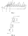
- the invention applies to strips comprising several socket outlets A connected in series and one unitary device B for switching on or off as shown schematically in Figure 1.
- These rods are generally formed by a fairly long frame to present on its front face the number of bases A requested, usually one to eight, and in which are arranged supply and ground conductors Earth.
- the slide shown in Figure 1 carries a means of the energizing device or off tension near the end where they are connected to the current distribution circuit, by example by a cable D.
- This means can be a switch with two stable positions as shown in the drawing, a changing press button status with each press or any other control means by pulses, for example a touch button.
- This way can be unique as shown in the drawing, or the user may have at its disposal several such means connected by a back-and-forth system or by mounting with relay.
- the socket outlets are for example sockets allowing the passage of 16 Amps under 230 Volts.
- the strip includes a device for control C of switching on or off as that it ensures the powering of the bases during the zero crossing of the voltage so as to avoid current calls, this control device is provided a sequencing device ensuring a deactivation service of the bases at instants distributed over time after the strip power off command.
- a microprocessor provided in the control device receives the power-on command from the unitary control device, this microprocessor controls the power of the bases of the strip at an instant following receipt of the order for which the voltage is nothing.
- the sequencing device is such that following the order of switching off, the bases are successively turned off at different times.
- Electric arcs due to power off are only therefore not completely avoided but are reduced. Their impact on the electrical device is further minimized by the fact that the devices connected to the strip are put successively de-energized one after the other.
- the control system for switching on and off of the strip proposed by the invention is a device inexpensive ensuring a reduction quite significant current draw and arcing problems encountered when using equipment electric.
- the device uses a clock synchronized with the mains voltage, or obtained by derivation, whose signals correspond to zero crossings of the voltage.
- bistable called type 1
- type 2 bistable 2
- pulse controlled by pulse
- the first base, base 1 is energized at the next clock signal t1 the instant t0 of command to power up the strip.
- the second base is energized at the time of signal t2 according to t1.
- the socket outlets are thus energized one after the other at spaced times in the times for which the voltage goes through zero.
- the time interval between two clock signals used for energizing two bases is chosen so as to allow energized equipment to establish their operation normal, i.e. to let the current call pass accompanying the start-up of an electrical appliance.
- this time interval is a minimum of 200 milliseconds. A such interval is sufficient for start-up many electrical appliances and presents the advantage of being weak enough not to be noticeable by the user.
- the clock signals are then provided every 200 milliseconds. It is of course possible to provide clock signals closer in time and from perform the power-on command only after a predetermined number of signals.
- the setting time of which regime is longer for example a VCR
- the powering of successive bases is then controlled every eight clock signals.
- the sequencing used to power off the bases are, in the example shown, made in the direction reverse as the base 8 is put out of service first of all at the clock signal delivered at time t'8 following the time of order.
- Base 1 is the last to be taken out of service at instant t'1.
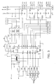
- FIG. 3 shows an embodiment of the module ensuring the control of power on and off of the bases of the slider.
- the power on and off device turns the resistance R4 in short circuit during the request for setting under pressure.
- This module includes a microprocessor U1 which perceives this state.
- the microprocessor U1 receives a clock signal on its entry 16.
- This microprocessor U1 delivers control signals on its outputs 8 to 13 and 17, 18.
- Output 17 controls the power stage E1 on which the power on and off of the base 1 depend.
- outputs 18, 13 and 12 respectively provide the control of the power stages E2, E3, E4 linked to the bases 2 to 4.
- FIG. 4 shows an embodiment of a power stage.
- this power stage is consisting of a triac whose trigger is controlled by a transistor.
- a suppressor is provided in this device.
- Such a power stage has a response time low and allows good order synchronization with the moment of zero crossing of the voltage.
- an additional set of four power stages is controlled by the outputs 8 to 11 while connected to terminals S1A, S2A, S3A and S4A provided for this purpose.
- the module is thus constituted for the piloting of four bases which corresponds to the most common uses current and is completed by the simple connection of a additional set for piloting a strip eight bases.
- the power on or off command is provided to the first strip.
- control device that this strip includes ensures the successive energization of the bases of this first strip then delivers at time t9 a signal of control of the second strip control device of the chain which in turn ensures the tensioning staggered plinths of this second front strip send a control signal to the control device a third strip. This procedure is repeated until the last base of the last strip of the chain.
- control modules have studs P1 to P4 accessible from the outside of the strip. Two of these pads, P3 and P4 provide the output of a signal command in the direction of another control module while that the other two, P1 and P2, allow the entry of such control signal.
- the first strip receives the control commands of a common device, for example a switch or press button as already described, we has a cable on pads P3 and P4 and connect it the other end of this cable to pads P1 and P2 of the module driving a second strip.
- a common device for example a switch or press button as already described
- the orders received on plots P1 and P2 by the second slider are used by its module like orders that it would receive from a type 2 control device.
- module of this second strip then carries out the orders power on or off requested then send again an order on its pads P3 and P4 so that it is set works in a third strip connected to it.
- the module is, of manufacture, designed to operate for a strip arranged in the first position in a chain, therefore receiving orders from the placing device on or off voltage, to obey a type 1 means, to control four bases with a time interval of 200 milliseconds.
- This module has four cut contacts 100 on which you can put a drop of solder to modify its basic functioning in order to inform it that it is not in first position, and / or that he must obey a type 2 command, and / or that he must control 8 bases, and / or that the interval must be 1600 milliseconds.
- the device according to the invention makes it possible to limit the magnetic pollution due to power on and off electrical appliances by reducing current draws and the current flashes in the line.
Landscapes
- Engineering & Computer Science (AREA)
- Power Engineering (AREA)
- Theoretical Computer Science (AREA)
- Physics & Mathematics (AREA)
- General Engineering & Computer Science (AREA)
- General Physics & Mathematics (AREA)
- Remote Monitoring And Control Of Power-Distribution Networks (AREA)
- Control Of Electrical Variables (AREA)
Description
- la mise sous tension des socles est également faite à des instants répartis dans le temps,
- la répartition dans le temps est commandée par un dispositif de séquencement,
- les mises hors service séquentielles des socles sont faites lors de passages par zéro de la tension,
- le dispositif de pilotage utilise une horloge synchronisée avec la tension du secteur dont les signaux correspondent à des passages par zéro de la tension,
- l'intervalle de temps séparant deux instants répartis dans le temps est au minimum de 200 millisecondes,
- l'intervalle de temps séparant deux instants répartis dans le temps est un nombre entier de fois 200 millisecondes, par exemple 1600 millisecondes,
- le dispositif de pilotage peut recevoir et/ou fournir un signal de commande d'un autre (à un autre) dispositif de pilotage auquel il est relié.
- la figure 1 montre une réglette comportant plusieurs socles selon l'invention,
- la figure 2 est un diagramme temporel représentant l'état de différents éléments du dispositif,
- la figure 3 montre un exemple de réalisation du module de pilotage suivant l'invention,
- la figure 4 est un exemple de réalisation des modules de puissance utilisés dans le module représenté à la figure 3.
Claims (8)
- Réglette du type comportant plusieurs socles de prises de courant (A) et un dispositif unitaire (B) de commande de la mise sous et hors tension desdits socles, caractérisée en ce qu'elle comporte un dispositif de pilotage (C) de la mise sous et hors tension des socles assurant la mise sous tension des socles lors d'un passage par zéro de la tension et une mise hors tension des socles à des instants répartis dans le temps.
- Réglette selon la revendication 1, caractérisée en ce que la mise sous tension des socles est également faite à des instants répartis dans le temps.
- Réglette selon la revendication 1 ou la revendication 2, caractérisée en ce que la répartition dans le temps est commandée par un dispositif de séquencement.
- Réglette selon l'une quelconque des revendications précédentes, caractérisée en ce que les mises hors service des socles sont faites lors de passages par zéro de la tension.
- Réglette selon l'une quelconque des revendications précédentes, caractérisée en ce que le dispositif de pilotage utilise une horloge synchronisée avec la tension du secteur dont les signaux correspondent à des passages par zéro de la tension.
- Réglette selon l'une quelconque des revendications 1 à 5, caractérisée en ce que l'intervalle de temps séparant deux instants répartis dans le temps est au minimum de 200 millisecondes.
- Réglette selon la revendication 6, caractérisée en ce que l'intervalle de temps séparant deux instants répartis dans le temps est un nombre entier de fois 200 millisecondes, par exemple 1600 millisecondes.
- Réglette selon l'une quelconque des revendications 1 à 7, caractérisée en ce que le dispositif de pilotage peut recevoir et/ou fournir un signal de commande d'un autre (à un autre) dispositif de pilotage auquel il est relié.
Applications Claiming Priority (2)
| Application Number | Priority Date | Filing Date | Title |
|---|---|---|---|
| FR9414505 | 1994-12-02 | ||
| FR9414505A FR2727774A1 (fr) | 1994-12-02 | 1994-12-02 | Reglette du type comportant plusieurs socles de prises de courant et un dispositif unitaire de commande de la mise sous et hors tension desdits socles |
Publications (2)
| Publication Number | Publication Date |
|---|---|
| EP0715387A1 EP0715387A1 (fr) | 1996-06-05 |
| EP0715387B1 true EP0715387B1 (fr) | 1999-03-24 |
Family
ID=9469416
Family Applications (1)
| Application Number | Title | Priority Date | Filing Date |
|---|---|---|---|
| EP95402712A Expired - Lifetime EP0715387B1 (fr) | 1994-12-02 | 1995-12-01 | Réglette du type comportant plusieurs socles de prises de courant et un dispositif unitaire de commande de la mise sous et hors tension desdits socles |
Country Status (3)
| Country | Link |
|---|---|
| EP (1) | EP0715387B1 (fr) |
| DE (1) | DE69508537T2 (fr) |
| FR (1) | FR2727774A1 (fr) |
Cited By (1)
| Publication number | Priority date | Publication date | Assignee | Title |
|---|---|---|---|---|
| CN110350370A (zh) * | 2019-07-17 | 2019-10-18 | 南京伊科诺电气科技有限公司 | 一种智能插座及其过零投切方法 |
Families Citing this family (1)
| Publication number | Priority date | Publication date | Assignee | Title |
|---|---|---|---|---|
| FR2988187B1 (fr) * | 2012-03-19 | 2015-05-01 | Professional General Elect | Carte electronique et ensemble de cartes maitre et esclave. |
Family Cites Families (3)
| Publication number | Priority date | Publication date | Assignee | Title |
|---|---|---|---|---|
| JP3056765B2 (ja) * | 1990-05-09 | 2000-06-26 | 株式会社リコー | 画像形成装置 |
| DE9015518U1 (fr) * | 1990-06-26 | 1991-03-28 | Krug, Mathias, 8959 Rosshaupten, De | |
| US5424903A (en) * | 1993-01-12 | 1995-06-13 | Tandy Corporation | Intelligent power switcher |
-
1994
- 1994-12-02 FR FR9414505A patent/FR2727774A1/fr active Granted
-
1995
- 1995-12-01 DE DE69508537T patent/DE69508537T2/de not_active Expired - Lifetime
- 1995-12-01 EP EP95402712A patent/EP0715387B1/fr not_active Expired - Lifetime
Cited By (1)
| Publication number | Priority date | Publication date | Assignee | Title |
|---|---|---|---|---|
| CN110350370A (zh) * | 2019-07-17 | 2019-10-18 | 南京伊科诺电气科技有限公司 | 一种智能插座及其过零投切方法 |
Also Published As
| Publication number | Publication date |
|---|---|
| DE69508537D1 (de) | 1999-04-29 |
| DE69508537T2 (de) | 1999-11-25 |
| EP0715387A1 (fr) | 1996-06-05 |
| FR2727774B1 (fr) | 1997-02-14 |
| FR2727774A1 (fr) | 1996-06-07 |
Similar Documents
| Publication | Publication Date | Title |
|---|---|---|
| FR2589295A1 (fr) | Dispositif de commande de charge receptrice | |
| EP0715387B1 (fr) | Réglette du type comportant plusieurs socles de prises de courant et un dispositif unitaire de commande de la mise sous et hors tension desdits socles | |
| FR2658377A3 (fr) | Dispositif de commande d'eclairage electrique. | |
| FR2568733A1 (fr) | Dispositif de commande de moteur electrique pour appareil a cintrer des tubes | |
| EP0576370A1 (fr) | Dispositif à encombrement limité pour commander un organe moteur de déplacement d'un élément d'occultation | |
| FR2488476A1 (fr) | Circuits de commande et ensembles de commutation electrique comprenant de tels circuits | |
| FR2593336A1 (fr) | Dispositif de commande des appareils electriques | |
| EP1779351B1 (fr) | Actionneur electrique de volet roulant avec interface de commande a contacts electriques a ouverture | |
| FR2550356A1 (fr) | Installations de commande multiplexee d'organes alimentes en courant electrique alternatif, tels que des lampes et moteurs | |
| EP0304363A1 (fr) | Régulateur de puissance, notamment pour le balisage d'aéroports | |
| EP0837537B1 (fr) | Dispositif de commande par télérupteur programmable | |
| EP0252816B1 (fr) | Programmateur de commande de lave-linge à microprocesseur, et composant électromécanique | |
| EP0614259B1 (fr) | Interrupteur différentiel de protection contre les courants de défaut et les surtensions | |
| EP0847229B1 (fr) | Dispositif commutateur-variateur pour réseaux électriques | |
| FR2477282A1 (fr) | Dispositif de controle de la capacite de batteries d'accumulateurs | |
| FR3076392A1 (fr) | Systeme de commande electrique comportant plusieurs points de commande et appareillage electrique mis en œuvre dans un tel systeme de commande | |
| FR2492183A1 (fr) | Perfectionnement aux dispositifs de telecommande par trai ns d'impulsions sur les reseaux de distribution electrique | |
| FR2956534A1 (fr) | Dispositif de maintien de l'alimentation d'un appareil electrique raccorde a un reseau electrique fonctionnant selon des periodes tarifaires par contacteur ou programmateur | |
| FR2554287A1 (fr) | Dispositif matriciel d'interconnexion entre secteur et circuits d'utilisation | |
| EP0290314B1 (fr) | Circuit de commande pour appareils de télécommande électriques, notamment télérupteurs, et appareils incorporant ce circuit | |
| FR2565015A1 (fr) | Systeme d'affichage d'un segment, notamment utilise dans un affichage numerique telecommande | |
| BE504359A (fr) | ||
| FR3080228A1 (fr) | Dispositif electronique de coupure | |
| FR2825932A1 (fr) | Installation de commande pour des jouets actionnables electriquement et leur utilisation | |
| FR2987707A1 (fr) | Variateur electrique a deux fils |
Legal Events
| Date | Code | Title | Description |
|---|---|---|---|
| PUAI | Public reference made under article 153(3) epc to a published international application that has entered the european phase |
Free format text: ORIGINAL CODE: 0009012 |
|
| AK | Designated contracting states |
Kind code of ref document: A1 Designated state(s): DE FR |
|
| 17P | Request for examination filed |
Effective date: 19960807 |
|
| 17Q | First examination report despatched |
Effective date: 19970808 |
|
| GRAG | Despatch of communication of intention to grant |
Free format text: ORIGINAL CODE: EPIDOS AGRA |
|
| GRAG | Despatch of communication of intention to grant |
Free format text: ORIGINAL CODE: EPIDOS AGRA |
|
| GRAG | Despatch of communication of intention to grant |
Free format text: ORIGINAL CODE: EPIDOS AGRA |
|
| GRAH | Despatch of communication of intention to grant a patent |
Free format text: ORIGINAL CODE: EPIDOS IGRA |
|
| GRAH | Despatch of communication of intention to grant a patent |
Free format text: ORIGINAL CODE: EPIDOS IGRA |
|
| GRAA | (expected) grant |
Free format text: ORIGINAL CODE: 0009210 |
|
| AK | Designated contracting states |
Kind code of ref document: B1 Designated state(s): DE FR |
|
| REF | Corresponds to: |
Ref document number: 69508537 Country of ref document: DE Date of ref document: 19990429 |
|
| PLBE | No opposition filed within time limit |
Free format text: ORIGINAL CODE: 0009261 |
|
| STAA | Information on the status of an ep patent application or granted ep patent |
Free format text: STATUS: NO OPPOSITION FILED WITHIN TIME LIMIT |
|
| 26N | No opposition filed | ||
| PGFP | Annual fee paid to national office [announced via postgrant information from national office to epo] |
Ref country code: DE Payment date: 20120629 Year of fee payment: 17 |
|
| REG | Reference to a national code |
Ref country code: FR Ref legal event code: TP Owner name: ENSTO INDUSTRIE, FR Effective date: 20130906 |
|
| PG25 | Lapsed in a contracting state [announced via postgrant information from national office to epo] |
Ref country code: DE Free format text: LAPSE BECAUSE OF NON-PAYMENT OF DUE FEES Effective date: 20130702 |
|
| REG | Reference to a national code |
Ref country code: DE Ref legal event code: R119 Ref document number: 69508537 Country of ref document: DE Effective date: 20130702 |
|
| PGFP | Annual fee paid to national office [announced via postgrant information from national office to epo] |
Ref country code: FR Payment date: 20130716 Year of fee payment: 18 |
|
| REG | Reference to a national code |
Ref country code: FR Ref legal event code: ST Effective date: 20140829 |
|
| PG25 | Lapsed in a contracting state [announced via postgrant information from national office to epo] |
Ref country code: FR Free format text: LAPSE BECAUSE OF NON-PAYMENT OF DUE FEES Effective date: 20131231 |