EP0715301A2 - Data recording media and recording/reproduction thereof - Google Patents
Data recording media and recording/reproduction thereof Download PDFInfo
- Publication number
- EP0715301A2 EP0715301A2 EP95308598A EP95308598A EP0715301A2 EP 0715301 A2 EP0715301 A2 EP 0715301A2 EP 95308598 A EP95308598 A EP 95308598A EP 95308598 A EP95308598 A EP 95308598A EP 0715301 A2 EP0715301 A2 EP 0715301A2
- Authority
- EP
- European Patent Office
- Prior art keywords
- recording
- data
- layer
- disk
- sector
- Prior art date
- Legal status (The legal status is an assumption and is not a legal conclusion. Google has not performed a legal analysis and makes no representation as to the accuracy of the status listed.)
- Granted
Links
Images


Classifications
-
- G—PHYSICS
- G11—INFORMATION STORAGE
- G11B—INFORMATION STORAGE BASED ON RELATIVE MOVEMENT BETWEEN RECORD CARRIER AND TRANSDUCER
- G11B20/00—Signal processing not specific to the method of recording or reproducing; Circuits therefor
- G11B20/10—Digital recording or reproducing
- G11B20/12—Formatting, e.g. arrangement of data block or words on the record carriers
- G11B20/1217—Formatting, e.g. arrangement of data block or words on the record carriers on discs
-
- G—PHYSICS
- G11—INFORMATION STORAGE
- G11B—INFORMATION STORAGE BASED ON RELATIVE MOVEMENT BETWEEN RECORD CARRIER AND TRANSDUCER
- G11B5/00—Recording by magnetisation or demagnetisation of a record carrier; Reproducing by magnetic means; Record carriers therefor
- G11B5/02—Recording, reproducing, or erasing methods; Read, write or erase circuits therefor
-
- G—PHYSICS
- G11—INFORMATION STORAGE
- G11B—INFORMATION STORAGE BASED ON RELATIVE MOVEMENT BETWEEN RECORD CARRIER AND TRANSDUCER
- G11B27/00—Editing; Indexing; Addressing; Timing or synchronising; Monitoring; Measuring tape travel
- G11B27/10—Indexing; Addressing; Timing or synchronising; Measuring tape travel
- G11B27/19—Indexing; Addressing; Timing or synchronising; Measuring tape travel by using information detectable on the record carrier
- G11B27/28—Indexing; Addressing; Timing or synchronising; Measuring tape travel by using information detectable on the record carrier by using information signals recorded by the same method as the main recording
- G11B27/32—Indexing; Addressing; Timing or synchronising; Measuring tape travel by using information detectable on the record carrier by using information signals recorded by the same method as the main recording on separate auxiliary tracks of the same or an auxiliary record carrier
- G11B27/327—Table of contents
- G11B27/329—Table of contents on a disc [VTOC]
-
- G—PHYSICS
- G11—INFORMATION STORAGE
- G11B—INFORMATION STORAGE BASED ON RELATIVE MOVEMENT BETWEEN RECORD CARRIER AND TRANSDUCER
- G11B7/00—Recording or reproducing by optical means, e.g. recording using a thermal beam of optical radiation by modifying optical properties or the physical structure, reproducing using an optical beam at lower power by sensing optical properties; Record carriers therefor
- G11B7/007—Arrangement of the information on the record carrier, e.g. form of tracks, actual track shape, e.g. wobbled, or cross-section, e.g. v-shaped; Sequential information structures, e.g. sectoring or header formats within a track
- G11B7/00745—Sectoring or header formats within a track
-
- G—PHYSICS
- G11—INFORMATION STORAGE
- G11B—INFORMATION STORAGE BASED ON RELATIVE MOVEMENT BETWEEN RECORD CARRIER AND TRANSDUCER
- G11B7/00—Recording or reproducing by optical means, e.g. recording using a thermal beam of optical radiation by modifying optical properties or the physical structure, reproducing using an optical beam at lower power by sensing optical properties; Record carriers therefor
- G11B7/24—Record carriers characterised by shape, structure or physical properties, or by the selection of the material
-
- H—ELECTRICITY
- H04—ELECTRIC COMMUNICATION TECHNIQUE
- H04N—PICTORIAL COMMUNICATION, e.g. TELEVISION
- H04N9/00—Details of colour television systems
- H04N9/79—Processing of colour television signals in connection with recording
- H04N9/87—Regeneration of colour television signals
- H04N9/877—Regeneration of colour television signals by assembling picture element blocks in an intermediate memory
-
- G—PHYSICS
- G11—INFORMATION STORAGE
- G11B—INFORMATION STORAGE BASED ON RELATIVE MOVEMENT BETWEEN RECORD CARRIER AND TRANSDUCER
- G11B7/00—Recording or reproducing by optical means, e.g. recording using a thermal beam of optical radiation by modifying optical properties or the physical structure, reproducing using an optical beam at lower power by sensing optical properties; Record carriers therefor
- G11B2007/0003—Recording, reproducing or erasing systems characterised by the structure or type of the carrier
- G11B2007/0009—Recording, reproducing or erasing systems characterised by the structure or type of the carrier for carriers having data stored in three dimensions, e.g. volume storage
- G11B2007/0013—Recording, reproducing or erasing systems characterised by the structure or type of the carrier for carriers having data stored in three dimensions, e.g. volume storage for carriers having multiple discrete layers
-
- G—PHYSICS
- G11—INFORMATION STORAGE
- G11B—INFORMATION STORAGE BASED ON RELATIVE MOVEMENT BETWEEN RECORD CARRIER AND TRANSDUCER
- G11B20/00—Signal processing not specific to the method of recording or reproducing; Circuits therefor
- G11B20/10—Digital recording or reproducing
- G11B20/12—Formatting, e.g. arrangement of data block or words on the record carriers
- G11B20/1217—Formatting, e.g. arrangement of data block or words on the record carriers on discs
- G11B2020/1218—Formatting, e.g. arrangement of data block or words on the record carriers on discs wherein the formatting concerns a specific area of the disc
- G11B2020/1228—Formatting, e.g. arrangement of data block or words on the record carriers on discs wherein the formatting concerns a specific area of the disc middle zone or outer guard area of a multilayer disc
-
- G—PHYSICS
- G11—INFORMATION STORAGE
- G11B—INFORMATION STORAGE BASED ON RELATIVE MOVEMENT BETWEEN RECORD CARRIER AND TRANSDUCER
- G11B20/00—Signal processing not specific to the method of recording or reproducing; Circuits therefor
- G11B20/10—Digital recording or reproducing
- G11B20/12—Formatting, e.g. arrangement of data block or words on the record carriers
- G11B2020/1264—Formatting, e.g. arrangement of data block or words on the record carriers wherein the formatting concerns a specific kind of data
- G11B2020/1265—Control data, system data or management information, i.e. data used to access or process user data
- G11B2020/1267—Address data
-
- G—PHYSICS
- G11—INFORMATION STORAGE
- G11B—INFORMATION STORAGE BASED ON RELATIVE MOVEMENT BETWEEN RECORD CARRIER AND TRANSDUCER
- G11B20/00—Signal processing not specific to the method of recording or reproducing; Circuits therefor
- G11B20/10—Digital recording or reproducing
- G11B20/12—Formatting, e.g. arrangement of data block or words on the record carriers
- G11B2020/1264—Formatting, e.g. arrangement of data block or words on the record carriers wherein the formatting concerns a specific kind of data
- G11B2020/1288—Formatting by padding empty spaces with dummy data, e.g. writing zeroes or random data when de-icing optical discs
-
- G—PHYSICS
- G11—INFORMATION STORAGE
- G11B—INFORMATION STORAGE BASED ON RELATIVE MOVEMENT BETWEEN RECORD CARRIER AND TRANSDUCER
- G11B20/00—Signal processing not specific to the method of recording or reproducing; Circuits therefor
- G11B20/10—Digital recording or reproducing
- G11B20/12—Formatting, e.g. arrangement of data block or words on the record carriers
- G11B2020/1264—Formatting, e.g. arrangement of data block or words on the record carriers wherein the formatting concerns a specific kind of data
- G11B2020/1289—Formatting of user data
-
- G—PHYSICS
- G11—INFORMATION STORAGE
- G11B—INFORMATION STORAGE BASED ON RELATIVE MOVEMENT BETWEEN RECORD CARRIER AND TRANSDUCER
- G11B20/00—Signal processing not specific to the method of recording or reproducing; Circuits therefor
- G11B20/10—Digital recording or reproducing
- G11B20/12—Formatting, e.g. arrangement of data block or words on the record carriers
- G11B2020/1291—Formatting, e.g. arrangement of data block or words on the record carriers wherein the formatting serves a specific purpose
- G11B2020/1294—Increase of the access speed
-
- G—PHYSICS
- G11—INFORMATION STORAGE
- G11B—INFORMATION STORAGE BASED ON RELATIVE MOVEMENT BETWEEN RECORD CARRIER AND TRANSDUCER
- G11B2220/00—Record carriers by type
- G11B2220/20—Disc-shaped record carriers
- G11B2220/23—Disc-shaped record carriers characterised in that the disc has a specific layer structure
- G11B2220/235—Multilayer discs, i.e. multiple recording layers accessed from the same side
-
- G—PHYSICS
- G11—INFORMATION STORAGE
- G11B—INFORMATION STORAGE BASED ON RELATIVE MOVEMENT BETWEEN RECORD CARRIER AND TRANSDUCER
- G11B2220/00—Record carriers by type
- G11B2220/20—Disc-shaped record carriers
- G11B2220/25—Disc-shaped record carriers characterised in that the disc is based on a specific recording technology
- G11B2220/2537—Optical discs
-
- H—ELECTRICITY
- H04—ELECTRIC COMMUNICATION TECHNIQUE
- H04N—PICTORIAL COMMUNICATION, e.g. TELEVISION
- H04N5/00—Details of television systems
- H04N5/76—Television signal recording
- H04N5/84—Television signal recording using optical recording
- H04N5/85—Television signal recording using optical recording on discs or drums
-
- H—ELECTRICITY
- H04—ELECTRIC COMMUNICATION TECHNIQUE
- H04N—PICTORIAL COMMUNICATION, e.g. TELEVISION
- H04N9/00—Details of colour television systems
- H04N9/79—Processing of colour television signals in connection with recording
- H04N9/80—Transformation of the television signal for recording, e.g. modulation, frequency changing; Inverse transformation for playback
- H04N9/804—Transformation of the television signal for recording, e.g. modulation, frequency changing; Inverse transformation for playback involving pulse code modulation of the colour picture signal components
- H04N9/8042—Transformation of the television signal for recording, e.g. modulation, frequency changing; Inverse transformation for playback involving pulse code modulation of the colour picture signal components involving data reduction
Definitions
- This invention relates to data recording media suitable for recording digital signals, for example, and to record/playback apparatus therefor.
- a disk-shaped data recording medium comprising:
- Embodiments of the invention provide a data recording medium and a record/playback apparatus using the data recording medium.
- data On the data area of each layer of an embodiment, data has a sector structure, and each sector contains the number of total recording layers on the disk.
- Recording areas may be provided such that an inner guard area of a respective layer overlaps with an outer guard area of another layer, and TOC areas may contain at least data for access to all layers and data for identifying respective layers.
- the TOC areas on the uppermost layer may be provided in a location contiguous to the data area on the uppermost layer.
- the data area of each layer has a sector structure, and sector numbers of respective sectors can be determined according to a numbering system enabling identification of at least the layer numbers.
- a record/playback apparatus using a data recording medium embodying the invention accesses the medium by utilizing the recording layers, TOC areas, sector structure, etc. of the medium.
- the data recording medium embodying the invention can be readily accessed because of the structure of the recording tracks. Therefore, the record/playback apparatus using the data recording medium embodying the invention can easily access the medium at a high speed.
- the embodiment is a multi-layered disk in which a plurality of recording layers are provided in the thickness direction of the disk 1.
- One of the recording layers nearest to the surface for confrontation with a pickup is referred to as the uppermost recording layer in the following description.
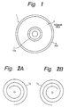
- Fig. 1 is a schematic view taken from above the disk 1 for explaining areas of the multi-layered disk embodying the invention.
- Numeral 2 denotes an inner guard area (called IGA), 3 a program area, and 4 an outer guard area (called OGA).
- IGA inner guard area
- OGA outer guard area
- the IGA is a read-in area
- the OGA is a read-out area.
- the OGA is a read-in area
- the IGA is a read-out area.
- the embodiment involves both making a spiral recording track departing from the inner side to the outer side of a disk and making a spiral recording track departing from the outer side to the inner side of a disk.
- layers to be recorded from the inner side to the outer side of the disk and layers to be recorded from the outer side to the inner side of the disk lie alternately.
- layers with even numbers, L0, L2,... are to be recorded from the inner side to the outer side of the disk while layers with odd numbers. L1, L3,... are to be recorded from the outer side to the inner side of the disk.
- the even numbers and odd numbers used here are reference numbers assigned to layers L only for the purpose of explanation, and the uppermost layer is assigned with an even number, L0, although it is in the first order.
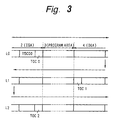
- Fig. 2A shows a spiral recording track Te of each layer having an even number, which is recorded from the inner side to the outer side of the disk as shown by the arrow mark.
- the recording track To of each layer having an odd number is spirally recorded from the outer side to the inner side of the disk.
- the uppermost layer is referred to as the 0-numbered layer, L0, on which recording proceeds from the inner side to the outer side of the disk.
- recording tracks are classified into those having forward spiral recording tracks Te and those having reverse spiral recording tracks To, depending of respective layers.
- the layers with forward spiral recording tracks Te and the layers with reverse spiral recording tracks To are disposed to appear alternately such that data is recorded on forward spiral recording tracks in even-numbered layers L0, L2,... and on reverse spiral recording tracks in odd-numbered layers L1, L3,...
- the uppermost layer L0 definitely has the forward spiral recording track Te (the same direction as that of typical CDs) in order that an erroneously loaded disk can be distinguished, even when the disk size is the same as that of typical CDs.
- program areas on the disk are formed to terminate at equivalent positions. That is, the final end of signals on each even-numbered layer and the initial end of signals on each odd-numbered layer lie on approximately the same radial positions on the disk. For example, the final end of signals on each even-numbered layer and the initial end of signals on each odd-numbered layer are positioned very close. Approximate coincidence of their radial positions is sufficient, and their angular positions need not be close. More specifically, the total amount of data to be recorded on a disk is calculated, and the pickup is turned back and moved from a layer to a lower layer upon recording a half amount of data, such that the final end of the data comes to the same radial position as that of the inner side of the upper layer. In this manner, repeated reproduction is facilitated, and the access speed for moving to a lower layer is increased. Therefore, as shown in Fig. 1 taken from above the disk, program areas of respective layers coincide.
- the inner side IGA is uniformed among respective layers.
- the OGA of a respective layer is also uniformed with that of one of the layers having the largest recording area (program area) in the recording medium, such that the IGA and the OGA can be identified in any layer when the reading layer is changed by focus jump from one layer to another near the inner side or the outer side of the disk.
- CDs the innermost data record prohibiting area and the end of data are detected through detection of read-in/read-out areas.
- this is effective because CDs are single-layered.
- the disk embodying the invention having a plurality of layers, even when data ends at a radial position of a certain layer, another layer may have data recorded beyond the same radial position.
- empty data for example, data comprising a string of zero
- Tracks having recorded empty data are called empty tracks. If empty data is not recorded, then it may occur that sector head information cannot be found when the reading layer is changed by focus jump from a layer with data to another without data. When sector head information is not obtained, control onto the pickup and servo control will be difficult.
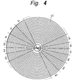
- Fig. 3 shows layout of recording tracks, showing respective layers in a cross-sectional view of the disk.
- Numeral 2 denotes the IGA
- 3 denotes program areas
- 4 labels the OGA. Arrows show moving directions of the pickup.
- the TOC of all layers (TOC00) is recorded on the uppermost layer.
- the states of all layers of the disk can be identified with reference to the IGA of the first layer L0 alone. If the first layer L0 contains the TOC of another layer, TOC00 for example, then the TOC0 on its own layer is recorded in a location nearest to the program area to facilitate identification from the other layer. Thus the time from the IGA to the start of the program can be shortened.
- the TOC00 contains important data defining the disk. For example, if both conventional single-layered disks and multi-layered disks are acceptable as standard disks, then the TOC00 contains ID for distinguishing whether a disk is single-layered or multi-layered. In another example, the TOC00 contains information indicating the total layers of a multi-layered disk. Further, by linking with the TOC0 to the TOCn of respective layers, the TOC00 can be first accessed upon an access request to determine the TOC of which layer is to be next accessed. Moreover, the TOC00 may contain the largest radius of program areas of all layers to prevent the pickup from reading areas beyond the largest radius. Therefore, when different disks with different sizes are standardized, overrun (dropout of the pickup from the program area) on a small-sized disk can be prevented.
- Fig. 4 schematically shows the sector structure of the first layer L0.
- a disk of a constant angular velocity (CAV) type is taken for simplicity.
- a disk of a constant linear velocity (CLV) type is used considering the recording density.
- Data on each layer is recorded in the unit of sectors (00 to 255). Considering that the data of all layers constitutes a single program, it is easy to assign consecutive numbers to sector addresses of a plurality of layers. For example, in the second layer not shown, sector addresses (256 to 511) are used, and in the third layer, sector addresses (512 to 767) are used. Moreover, description of layer numbers is necessary to facilitate selection of a respective layer.
- the layer number of each sector is recorded on the sub-code SC.
- the cutting direction such as from the inner side to the outer side of the disk (or the vice versa), reverse spiral, or the like, is preferably recorded on the sub-code SC.
- layer information recorded on the sub-code Sc contains the number of total recording layers on the disk in addition to the layer number.
- Fig. 6 shows such an example.
- a one-byte layer field contains the field of the 3-bit number (b5 to b3) of total layers and the field of the 3-bit (b2 to b0) layer number.
- Fig. 8 shows definition of layer numbers. Although only layer numbers L0 and L1 are defined here, the usage of the field is the same as shown in Fig.s 5A and 5B.
- Fig. 7 shows definition of numbers of total layers. Here are defined 1 and 2 as numbers of total recording layers. For example, if both conventional single-layered disks and multi-layered disks are acceptable as standard disks, this field is used for determining whether a disk is single ⁇ layered or multi-layered.
- Header information such as sector address.
- Header information contains a track number, sector address, copyright code, application code, and so forth, in addition to the layer number.
- Each track number is a 16-bit code, and values (0 to 65533) are assigned as track numbers in the program area of the disk, in which 65534 is the track number of the OGA and 65535 is the track number of the IGA.
- Each sector address has the length of 24 bits. In the following description, $ represents 16 digits.
- Each sector address is a 24-bit two-complement code.
- forward spiral layers L0, L2,... the sector address increases from the inner side to the outer side of the disk.
- reverse spiral layers L1, L3,... the sector address increases from the outer side to the inner side of the disk. If recording is started from the innermost $000000 in forward spiral layers, then recording on reverse spiral layers is done such that the innermost sector address becomes $800000, for example.
- SAd1 SAd0 XOR $7FFFFF
- sector addresses at the same radial position in both forward spiral layers and reverse spiral layers can be converted by a simple calculation because the exclusive logical sum (XOR) with $7FFFFF may be calculated.
- the servo circuit In case of CLV disks, in particular, the number of sectors in one track varies with the radius. Therefore, it is effective for the servo circuit to use a current position (radial information) of the pickup to know the number of tracks to be jumped over upon accessing a particular sector. Radial information can be obtained also from the sector address by reference to the table, for example. In this case, if sector addresses are determined with no consideration about the forward spiral direction and the reverse spiral direction, then different tables must be prepared for the forward spiral direction and for the reverse spiral direction. If the outermost sector address is not standardized, then radial information is not calculated from the reference table, and calculation or measurement of the number of total sectors in one track will be required.
- this example is configured to assign sector numbers that makes it easy to convert sector addresses either in forward spiral layers or in reverse spiral layers by simple calculation, each sector address on either layer can be easily converted into radial information. Thus the amount of tables required can be reduced, and high-speed access is realized.
- Fig. 9 shows a disk layout with addresses determined in the above-explained manner.
- the sector address of the last sector in the IGA (inner guard area) of layer L0 is equal to (-1).
- the track number for all sectors in the IG3 is equal to 65535.
- the application code of all sectors in the IGA is equal to 0.
- the number of sectors in all program areas of a disk is equal. Unused tracks in the program area or areas of a disk are encoded as empty tracks.
- the innermost (first) sector of the program area of layer L0 is equal to 0 (that is, $000000).
- the outermost (last) sector address of the program area of layer L1 is equal to $7FFFFF.
- the relation referred to above, namely ($7FFFFF $00000 XOR $7FFFFF) exists between these both.
- Fig. 9 shows an example of a dual layer disk with three tracks in the program area of layer L0 and two tracks in the program area of layer L1. For example, tracks 0, 1, 2 and 3 contain user data, and track 4 is an empty track.
- the track number of the first track of layer L1 is equal to the highest track number of layer L0 incremented by one.
- the first sector address of the OGA (outer guard area) of layer L0 is equal to the last sector address in the program area incremented by one.
- the track number of all sectors in the OGA is equal to 65534.
- the application code of all sectors in the OGA is equal to 0. In single-layered disks, the layout of layer L0 can be used.
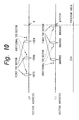
- Fig. 10 shows the location of the TOC on a dual layer disk.
- Each layer contain three copies of the TOC.
- the TOC of each layer is located in the IGA, and includes a first TOC and an additional TOC.
- the TOC is recorded as one or more consecutive sectors.
- the first sector addresses of the TOC are: -3072,-2048 and -1024.
- the first sector addresses of the TOC are: (-1 XOR $7FFFFF), (-1025 XOR $7FFFFF) and (-2049 XOR $7FFFFF).
- the location of the TOC of layer L0 is applicable.
- the layout of the first TOC sector is given in Fig. 11. Individual fields are explained below.
- the "System ID” contains "HDCD” coded according to ISO 646.
- the "System Version Number” is the version number of the high density CD system description used for the disk.
- the first two bytes contain the major version number encoded according to ISO 646, and the last two bytes contain the minor version number encoded according to ISO 646.
- the major version number is "01"
- the minor version number is "00”.
- the "Number of TOC Sectors” is a two-byte field containing the encoded number of sectors in the TOC.
- the "TOC Sector Number” is an encoded number indicating the sequence of the sector in the entire TOC. "0” is always recorded for the first TOC sector.
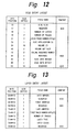
- the "Disc Entry” contains some parameters which indicate properties of the disk. The layout of the disc entry field is given in Fig. 12.
- the "Disk Size", for example, of the disc entry is a one-byte field containing the encoded outer diameter of the disk in mm. All bytes in the reserved field have the value $00.
- the "Number of Layers” is a one-byte field containing the encoded number of data recording layers on the disk.
- the “Number of Tracks” is a two-byte field containing the encoded number of total tracks on the disk.
- the "Logical Track Number Offset” is used as an offset value upon converting the physical track number to the logical track number. Although the physical track number is reset to "0" at the leading head of each disk, a single track number space can be made over a plurality of disks by using the "Logical Track Number Offset".
- the "Disc Application ID" contains the application code of the disk. If the disk contains one application code and zero or more empty tracks, then the disk application ID is equal to the track application code, or else the application ID is equal to $FF.
- the "Volume ID" is a 16-byte ISO 646 code and contains the identification of the disk.
- a group of disks with an identical volume ID is called a volume set.
- the number of disks in a volume set is encoded into two bytes of the volume set size.
- the address number of a sector containing the disk information is encoded into a 24 bit "Disk Information Sector".
- the disk information sector is a 2-complement code. If the disk information is not available for a disk, then the value of the disk information sector is set to -1.
- the byte offset within the user data field of the disk is encoded as the two-byte "Disk Information Offset”. If the disk information is not available for a disk, then the value of the disk information offset is set to $FFFF.
- the "Layer 0 Entry” contains information on the uppermost layer (L0), and the “Layer 1 Entry” contains information on L1. Their contents are absolutely the same.
- the layout of the "Layer Entry” is given in Fig. 13.
- the 16 bytes of the layer entry contain parameters of the layer in which the TOC is located.
- the Layer Number is a one-byte field indicating the number of the layer.
- the "First Address” gives the sector address of the first sector in the program area of the layer.
- the “First Address” is the lowest sector address value in the layer.
- the “Last Address” gives the sector address of the last sector in the program area of the layer.
- the “Last Address” is the highest sector address value in the layer.
- the "First Track Number Offset” (two bytes) gives the value of the first track number in the program area of the layer.
- the "Number of Tracks” gives the number of tracks in the program area of the layer.
- One byte of the "Layer Type" gives the type of the layer.
- the value 0 indicates the type I
- the value 1 indicates the type II
- the value 2 indicates the type III.
- Values $1 to $FF mean Reserved.
- the Reserved field has the value $00.
- the "Publisher Entry” is a 64-byte field containing information on the publisher of the disk.
- the "Manufacturer Entry” is a 32-byte field containing information on the manufacturer of the disk.
- the Reserved field has the value $00.
- Track Entry contains data on one track on the disk.
- Track Entry 0 contains data on the first track on the disk. All bytes in an unused Track Entry are set to $00.
- the layout of the Track Entry N is given in Fig. 14.
- 24 bits of the "Track Start Address” (2-complement code) give the sector address of the first sector in the track.
- the first sector in one track is the sector with the lowest Sector Address in the track.
- 24 bits of the "Track End Address” (2-complement code) give the sector address of the last sector in the track.
- the last sector in one track is the sector with the highest Sector Address in the track.
- the "Track Copyright Code” is a one-byte field. If the Copyright Codes for all sectors in the track are equal, then the Track Copyright Code is equal to the Copyright Code of the sectors in the track, or else the Track Copyright Code is equal to 255.
- the "Track Application Code" is a one-byte field. If the track is a single application track, then the Track Application Code is equal to the Application Code which is not empty. If the track is a mixed application track with sectors having a plurality of Application Codes, then the Track Application Code is equal to 255. If the Track Entry describes an empty track, then the Track Application Code is equal to 254.
- the "Track Information Sector” is a 24-bit 2-complement code, and indicates the address of the sector that contains the Track Information. If the Track Information is not available for the track, then the value is set to -1.
- the layout of the Additional TOC Sectors is given in Fig. 15.
- the value of Byte Position in Fig. 15 gives the start position of a field in the user data field of a sector.
- Byte Position 0 is the first byte in the user data field of a sector.
- Individual fields in the layout of the Addition TOC Sector have the same definition as that of the individual fields in the layout of the First TOC Sector shown in Fig. 11, and their explanation is omitted here.
- Fig. 16 shows an apparatus for decoding (encoded) variable-rate data, as an apparatus used for recording and reproducing digital data of moving pictures having a large amount of data according to the MPEG (Moving Pictures Expert Group) standard, for example.
- MPEG Motion Pictures Expert Group
- Fig. 16 data on the optical disk 11 is reproduced by a pickup 12.
- the pickup 12 irradiates laser light onto the optical disk 11, and reproduces the data on the optical disk 11 from the reflected light.
- the signal reproduced by the pickup 12 is sent to a demodulator 13 which in turn demodulates the reproduced signal from the pickup 12 and transfers it to a sector detector 14.
- the sector detector 14 detects sector data recorded on each sector from the data supplied, and supplies it to a layer separator 29.
- the layer separator 29 separates the sector address and the layer number from the sector data.
- the sector address SAd is supplied to a ring buffer controller 16, and the sector detector 14 outputs data to the next ECC circuit 15, keeping the sector synchronization. If the address is not detected or when the detected address is not contiguous, for example, then the sector detector 14 transfers a sector number error signal through the ring buffer controller 16 to a track jump detector 28. If the layer separator 29 cannot detect discontinuity of the layer number, or if the detected layer number is not equal, then the layer separator 29 supplies a layer number error signal through the ring buffer controller 16 to the track jump detector 28.
- An Ecc circuit 15 detects an error in data supplied from the sector detector circuit 14, then corrects the error using redundant bits added to the data, and transfers the corrected data to ring buffer memory (FIFO) 17 for track'jump.
- FIFO ring buffer memory
- the ring buffer controller 16 controls writing and reading of the ring buffer memory 17 and monitors a code request signal output from a multiplex data separator 18 to request data.
- the track jump discriminator 28 monitors the output of the ring buffer controller 16. When a track jump is required, the ring buffer controller 16 outputs a track jump signal to a track jump servo circuit 17 to have the pickup 12 jump from a track to another on the optical disk 11 under reproduction 11.
- the track jump discriminator 28 detects a sector number error signal from the sector detector 14, layer number error signal from the layer separator 29 and the error occurrence signal from the ECC circuit 15, and outputs a track jump signal to a tracking servo circuit 27 to have the pickup 12 jump from a track to another on the optical disk 11 under reproduction.
- Data output from the ring buffer memory 17 is applied to the multiplex data separator 18.
- the header separator 19 of the multiplex data separator 18 separates the pack header and the packet header from the data supplied from the ring buffer memory 17, supplies them to a separator control circuit 21, and at the same time supplies time-divisional multiplex data to the input terminal G of a switching circuit 20.
- Output terminals (selective terminals) H1, H2 of the switching circuit 20 are coupled to input terminals of a video code buffer 23 and an audio code buffer 25.
- An output of the video code buffer 23 is coupled to the input of the video decoder 24, and an output of the audio code buffer 25 to input of an audio decoder 26.
- a code request signal from the video decoder 24 enters in the video code buffer , and a code request signal from the video code buffer 23 enters in the multiplex data separator 18.
- the video data decoded by the video decoder 24 complies with the MPEG standard referred to above, in which three different pictures by three different coding methods, namely, intra-frame coded picture (normally called I picture), inter-frame predictive coded picture (normally called P picture ) and inter-frame bi-directional predictive coded picture (normally called B picture), make a predetermined group (called GOP).
- a code request signal from the audio decoder 26 enters in the audio coder buffer 25, and a code request signal from the audio code buffer 25 enters in the multiplex data separator 18.
- the audio data decoded by the audio decoder 26 may comply with the MPEG standard here again, or may be either compressed coded digital audio data or non-compressed audio data by ATRAC (trademark) proposed by the present Applicant.
- the pickup 12 irradiates laser light onto the optical disk 11, and reproduces data recorded on the optical disk 11 from the reflected light.
- the reproduction signal from the pickup 12 is supplied to and demodulated in the demodulator 13.
- Data demodulated by the demodulator 13 enters in the ECC circuit 15 via the sector detector 14 for detection and correction of errors. If the sector number (address assigned to each sector of the optical disk 11) is not properly detected, then a sector number error signal is output to the track jump discriminator 28. When uncorrectable data is found, the ECC circuit 15 outputs the error occurrence signal to the track jump discriminator 28.
- the corrected data is supplied from the ECC circuit 15 to the ring buffer memory 17, and stored there.
- Output (sector data) of the sector detector 14 is supplied to the layer separator 29, and separated into layer number LNo. and sector address SAd. Both the layer number and the sector address are supplied to the ring buffer controller 16. If the layer number (layer number recorded on a sector of the optical disk 11) is not detected normally in the layer separator 29, a layer number error signal is output to the track jump discriminator 28.
- the ring buffer controller 16 reads out the layer number LNo. and the sector address SAd, and designates a write address (write pointer (WP)) on the ring buffer memory 17 corresponding to the address Sad.
- WP write pointer
- the information about the optical disk 11, whether it is single-layered or multi-layered and how many layers it has, is important for the servo circuit. Therefore, on the first reproduction of the optical disk 11, the number of recording layer on the disk is given from the layer separator 19 to a drive controller, not shown, and to the racking servo circuit 27. Thus ensured is reliable reproduction.
- the ring buffer controller 16 designates a read address (read pointer (RP)) of data written in the ring buffer memory 17 on the basis of the code request signal from the next-stage multiplex data separator 18, then reads out data from the read pointer (RP), and supplies it to the multiplex data separator 18.
- RP read pointer
- the header separator 19 of the multiplex data separator 18 separates the pack header and the packet header from the data supplied from the ring buffer memory 17, and supplies them to the separator controlling circuit 21. Pursuant to the stream id information of the packet header supplied from the header separator 19, the separator control circuit 21 sequentially connects the input terminal G with the output terminals (selective terminals) H1, H2 to properly separate the time-divisional multiplex data, and supplies it to a corresponding code buffer.
- the video coder buffer 23 generates a code request to the multiplex data separator 18, depending on the amount of code buffer currently held inside, and stores received data.
- the video code buffer 23 accepts a code request from the video decoder 24, and supplies data held inside.
- the video decoder 24 reproduces the video signal from the supplied data, and outputs it through the output terminal 31.
- the audio code buffer 25 issues a code request to the multiplex data separator 18, and stores the received data.
- the audio code buffer 25 accepts a code request from the audio decoder 26 and supplies the data held inside.
- the audio decoder 26 reproduces the audio signal from the supplied data and outputs it through the output terminal 32.
- the video decoder 24 requests data to the video code buffer 23, the video code buffer 23 in turn issues a request to the multiplex data separator 18, and the multiplex data separator 18 issues a request to the ring buffer controller 16. Responsively, data flows from the buffer memory 17 in the opposite direction relative to the direction of the requests.
- the track jump discriminator 18 calculates (detects) the amount of data currently stored in the ring buffer memory 17 by means of the write pointer (WP) and read pointer (RP). When the amount of data exceeds a predetermined reference value, the track jump discriminator 18 determines a possibility of overflow in the ring buffer memory 17, and outputs a track jump command to the tracking servo circuit 27.
- WP write pointer
- RP read pointer
- the track jump discriminator When the track jump discriminator detects a sector number error signal from the sector detector 14 or an error occurrence signal from the ECC circuit 15, it calculates the amount of data held in the ring buffer memory 17 in view of the write pointer (WP) and the read pointer (RP), and determines a necessary amount of data for reliable reading from the ring buffer memory 17 to the multiplex data separator 18 during one revolution of the disk 11 (during the one-round waiting time of the disk 11).
- WP write pointer
- RP read pointer
- track jump discriminator 28 determines that the error can be corrected by again reproducing the location of the error by the pickup 12, and outputs a track jump command to the tracking servo circuit 27.
- the tracking servo circuit 27 makes the position for reproduction by the pickup 12 to jump to a one-track inner position. Then in the ring buffer controller 16, writing of a new data onto the ring buffer memory 17 is prohibited until the position for reproduction reaches the position before the jump after another revolution of the optical disk 11, that is, until the sector number obtained from the sector detector 14 coincides with the sector number just before the track jump, and data already stored in the ring buffer memory 17 is transferred to the multiplex data separator 18, if necessary.
- the sector address SAd When reproduction of the first layer is finished, the sector address SAd reaches a predetermined address, for example, address (255).
- the ring buffer controller 16 which detected the predetermined address supplies a layer switching signal to the focus servo circuit 30 and the tracking servo circuit 27.
- the focus servo circuit 30 changes over the focalization of the pickup 12 from the first layer to the second layer.
- the tracking servo circuit 27 interrupts the tracking servo control for a time until the changeover of the focalization to the second layer is accomplished. The reason why the tracking servo control is once interrupted is that no tracking error signal is obtained during dislocation of the focus from the first layer to the second layer.
- the first picture of the second layer is preferably a so-called Intra (I picture) to minimize the decoding time.
- the ring buffer memory 17 can store an amount of data corresponding to the time, and continuous reproduction of moving pictures is ensured.
- the same data may be written in both the outermost track of the first layer and the outermost track of the second layer such that the moving direction of the pickup can be inverted in a middle point of the track.
- a flag for inversion may be contained in a predetermined sector number, if the number of sectors is fixed, or on the sub-code of the sectors if the number of sectors is variable.
- a disk recording apparatus can be made by using a recordable disk such as magneto-optic disk, phase-change-type disk, and so forth, as the optical disk 11.
- a recordable disk such as magneto-optic disk, phase-change-type disk, and so forth
- sector synchronizing signals, sector addresses, and other like information are pre-formatted, and data is recorded in predetermined locations using the pre-formatted information.
- the uppermost recording layer has the recording direction from the inner side to the outer side, the recording direction may be opposite.
- the example uses spiral tracks, the invention is also applicable to a different example using concentric tracks.
- the data recording medium embodying the invention is configured to alternately change the recording direction among a plurality recording layers, it facilitates translation from a layer to another at a high speed and enables quick access.
- the record/playback apparatus for such data recording medium the changeover from a layer to another during recording or playback is smooth, and high-speed access is possible.
Abstract
Description
- This invention relates to data recording media suitable for recording digital signals, for example, and to record/playback apparatus therefor.
- Already known are multi-layered disks having a plurality of recording layers formed on a disk such that each layer is selectively read out under focus control of an optical pickup. For example, U.S. Patent No. 5,263,011 discloses one of such multi-layered disks and a record and playback apparatus using the disk.
- The technique on multi-layered disks by the above-identified document does not pay sufficient consideration for practical use, and it is still in the course of development. That is, no teaching is found about actual data writing and reading. In particular, no consideration is paid on recording and reproducing video data and/or audio data using compressed codes.
- In a conventional CD (compact disk), for example, its recording track is formed to start from the inner side to the outer side of the disk. However, there has been no disclosure on how to form recording tracks on a multi-layered disk. Therefore, conventional techniques having been employed for single-layered disks involve many problems to be discussed henceforth, although they are employable in some limited cases.
- According to one aspect of the invention, there is provided a disk-shaped data recording medium, comprising:
- at least a first and a second recording layers;
- a first recording direction from the inner side to the outer side of the medium and a second recording direction from the outer side to the inner side of the medium being determined as directions for recording data;
- one of the first and second recording directions being used as the recording direction of the first recording layer;
- the other of the first and second recording directions being used as the recording direction of the second recording layer; and
- each of the recording layers including a data area in which data has a sector structure, and each sector containing at least a layer number for identifying the first recording layer and the second recording layer.
- Respective further aspects of the invention are set forth in
claims - Embodiments of the invention provide a data recording medium and a record/playback apparatus using the data recording medium.
- On the data area of each layer of an embodiment, data has a sector structure, and each sector contains the number of total recording layers on the disk.
- Recording areas may be provided such that an inner guard area of a respective layer overlaps with an outer guard area of another layer, and TOC areas may contain at least data for access to all layers and data for identifying respective layers.
- The TOC areas on the uppermost layer may be provided in a location contiguous to the data area on the uppermost layer. The data area of each layer has a sector structure, and sector numbers of respective sectors can be determined according to a numbering system enabling identification of at least the layer numbers.
- A record/playback apparatus using a data recording medium embodying the invention accesses the medium by utilizing the recording layers, TOC areas, sector structure, etc. of the medium.
- The data recording medium embodying the invention can be readily accessed because of the structure of the recording tracks. Therefore, the record/playback apparatus using the data recording medium embodying the invention can easily access the medium at a high speed.
- Embodiments of the invention will now be described, by way of example, with reference to the accompanying drawings in which:
- Fig. 1 is a schematic view showing an aspect of divisional areas on a disk according to an embodiment of the invention;
- Figs. 2A and 2B are schematic views for explaining recording directions in an embodiment of the invention;
- Fig. 3 is a schematic view illustrating an example of locations of TOC on a disk embodying the invention;
- Fig. 4 is a schematic view of an example of dividing sectors on a disk embodying the invention;
- Figs. 5A and 5B are schematic views showing one and another examples of Sector Addresses;
- Fig. 6 is a schematic view showing an example of the layer field;
- Fig. 7 is a schematic view showing an example of data that represents the Number of Layers in the layer field;
- Fig. 8 is a schematic view showing an example of data that represents the Layer Number in the layer field;
- Fig. 9 is a schematic view for explaining a still further example of Sector Addresses;
- Fig. 10 is a schematic view for explaining another example of locations of TOC;
- Fig. 11 is a schematic view for explaining data layout of the first TOC;
- Fig. 12 is a schematic view for explaining layout of Disc Entry layout in the first TOC;
- Fig. 13 is a schematic view for explaining layout of Layer Entry in the first TOC;
- Fig. 14 is a schematic view for explaining layout of Track Entry in the first TOC;
- Fig. 15 is a schematic view for explaining data layout of additional TOC; and
- Fig. 16 is a block diagram of a disk playback apparatus according to an embodiment of the invention.
- An embodiment of the invention is described below. The embodiment is a multi-layered disk in which a plurality of recording layers are provided in the thickness direction of the
disk 1. One of the recording layers nearest to the surface for confrontation with a pickup is referred to as the uppermost recording layer in the following description. Fig. 1 is a schematic view taken from above thedisk 1 for explaining areas of the multi-layered disk embodying the invention. Numeral 2 denotes an inner guard area (called IGA), 3 a program area, and 4 an outer guard area (called OGA). In case of the uppermost recording layer L0, the IGA is a read-in area, and the OGA is a read-out area. In the next layer L1, the OGA is a read-in area, and the IGA is a read-out area. - Explained below are structures of the respective layers with reference to Figs. 2A and 2B. The embodiment involves both making a spiral recording track departing from the inner side to the outer side of a disk and making a spiral recording track departing from the outer side to the inner side of a disk. As to the relationship between the plurality of layers, layers to be recorded from the inner side to the outer side of the disk and layers to be recorded from the outer side to the inner side of the disk lie alternately. Further, as an example, layers with even numbers, L0, L2,... are to be recorded from the inner side to the outer side of the disk while layers with odd numbers. L1, L3,... are to be recorded from the outer side to the inner side of the disk. The even numbers and odd numbers used here are reference numbers assigned to layers L only for the purpose of explanation, and the uppermost layer is assigned with an even number, L0, although it is in the first order.
- That is, Fig. 2A shows a spiral recording track Te of each layer having an even number, which is recorded from the inner side to the outer side of the disk as shown by the arrow mark. On the other hand, as shown in Fig. 2B, the recording track To of each layer having an odd number is spirally recorded from the outer side to the inner side of the disk. In this case, the uppermost layer is referred to as the 0-numbered layer, L0, on which recording proceeds from the inner side to the outer side of the disk.
- In terms of the spiral directions, recording tracks are classified into those having forward spiral recording tracks Te and those having reverse spiral recording tracks To, depending of respective layers. The layers with forward spiral recording tracks Te and the layers with reverse spiral recording tracks To are disposed to appear alternately such that data is recorded on forward spiral recording tracks in even-numbered layers L0, L2,... and on reverse spiral recording tracks in odd-numbered layers L1, L3,... The uppermost layer L0 definitely has the forward spiral recording track Te (the same direction as that of typical CDs) in order that an erroneously loaded disk can be distinguished, even when the disk size is the same as that of typical CDs.
- Returning back to Fig. 1, program areas on the disk are formed to terminate at equivalent positions. That is, the final end of signals on each even-numbered layer and the initial end of signals on each odd-numbered layer lie on approximately the same radial positions on the disk. For example, the final end of signals on each even-numbered layer and the initial end of signals on each odd-numbered layer are positioned very close. Approximate coincidence of their radial positions is sufficient, and their angular positions need not be close. More specifically, the total amount of data to be recorded on a disk is calculated, and the pickup is turned back and moved from a layer to a lower layer upon recording a half amount of data, such that the final end of the data comes to the same radial position as that of the inner side of the upper layer. In this manner, repeated reproduction is facilitated, and the access speed for moving to a lower layer is increased. Therefore, as shown in Fig. 1 taken from above the disk, program areas of respective layers coincide.
- Next explained are the IGA and the OGA. As shown in Fig. 1, the inner side IGA is uniformed among respective layers. The OGA of a respective layer is also uniformed with that of one of the layers having the largest recording area (program area) in the recording medium, such that the IGA and the OGA can be identified in any layer when the reading layer is changed by focus jump from one layer to another near the inner side or the outer side of the disk.
- In CDs, the innermost data record prohibiting area and the end of data are detected through detection of read-in/read-out areas. However, this is effective because CDs are single-layered. In case of the disk embodying the invention having a plurality of layers, even when data ends at a radial position of a certain layer, another layer may have data recorded beyond the same radial position.
- In this embodiment, even when data on a certain layer ends at a certain radial position, if another layer has data recorded beyond the same radial position, then empty data (for example, data comprising a string of zero) is recorded on the former layer up to the same radial position. Tracks having recorded empty data are called empty tracks. If empty data is not recorded, then it may occur that sector head information cannot be found when the reading layer is changed by focus jump from a layer with data to another without data. When sector head information is not obtained, control onto the pickup and servo control will be difficult.
- Next explained is the TOC (Table of Contents) with reference to Fig. 3. Fig. 3 shows layout of recording tracks, showing respective layers in a cross-sectional view of the disk.
Numeral 2 denotes the IGA, 3 denotes program areas, and 4 labels the OGA. Arrows show moving directions of the pickup. - Among even-numbered layers and odd-numbered layers, positions for recording the IGA and the OGA are uniformed. That is, the TOC of layer L0 (TOC0) and the TOC of layer L2 (TOC2) are located in the same area. Thus the time required for the IGA can be reduced.
- The TOC of all layers (TOC00) is recorded on the uppermost layer. Thus the states of all layers of the disk can be identified with reference to the IGA of the first layer L0 alone. If the first layer L0 contains the TOC of another layer, TOC00 for example, then the TOC0 on its own layer is recorded in a location nearest to the program area to facilitate identification from the other layer. Thus the time from the IGA to the start of the program can be shortened.
- The TOC00 contains important data defining the disk. For example, if both conventional single-layered disks and multi-layered disks are acceptable as standard disks, then the TOC00 contains ID for distinguishing whether a disk is single-layered or multi-layered. In another example, the TOC00 contains information indicating the total layers of a multi-layered disk. Further, by linking with the TOC0 to the TOCn of respective layers, the TOC00 can be first accessed upon an access request to determine the TOC of which layer is to be next accessed. Moreover, the TOC00 may contain the largest radius of program areas of all layers to prevent the pickup from reading areas beyond the largest radius. Therefore, when different disks with different sizes are standardized, overrun (dropout of the pickup from the program area) on a small-sized disk can be prevented.
- Data recorded on the disk has a sector structure. Sectors are explained below with reference to Figs. 4, 5A and 5B. Fig. 4 schematically shows the sector structure of the first layer L0. In the example of Fig. 4, a disk of a constant angular velocity (CAV) type is taken for simplicity. Actually, however, a disk of a constant linear velocity (CLV) type is used considering the recording density.
- Data on each layer is recorded in the unit of sectors (00 to 255). Considering that the data of all layers constitutes a single program, it is easy to assign consecutive numbers to sector addresses of a plurality of layers. For example, in the second layer not shown, sector addresses (256 to 511) are used, and in the third layer, sector addresses (512 to 767) are used. Moreover, description of layer numbers is necessary to facilitate selection of a respective layer.
- In this connection, as shown in Fig. 5A, the layer number of each sector is recorded on the sub-code SC. In addition to the layer number, the cutting direction, such as from the inner side to the outer side of the disk (or the vice versa), reverse spiral, or the like, is preferably recorded on the sub-code SC.
- In lieu of describing the layer number as the sub-code, combined codes with the layer number and sector addresses may be recorded as sector addresses of the multi-layered disk. That is, the layer number is added as a primary bit of sector addresses. In this case, the layer number of the uppermost layer must be 0. Therefore, sector addresses of the uppermost layer are (0000 to 0255). In regard of the other layers, the sequence of the layer numbers coincides with the physical sequence of the layers. It should be prevented to skip layer numbers or to substitute the order so as to facilitate the changeover from a layer to another.
- It is also possible that layer information recorded on the sub-code Sc contains the number of total recording layers on the disk in addition to the layer number. Fig. 6 shows such an example. In Fig. 6, a one-byte layer field contains the field of the 3-bit number (b5 to b3) of total layers and the field of the 3-bit (b2 to b0) layer number.
- Fig. 8 shows definition of layer numbers. Although only layer numbers L0 and L1 are defined here, the usage of the field is the same as shown in Fig.s 5A and 5B.
- Fig. 7 shows definition of numbers of total layers. Here are defined 1 and 2 as numbers of total recording layers. For example, if both conventional single-layered disks and multi-layered disks are acceptable as standard disks, this field is used for determining whether a disk is single^layered or multi-layered.
- Further explained is another example of sector header information such as sector address. Header information contains a track number, sector address, copyright code, application code, and so forth, in addition to the layer number. Each track number is a 16-bit code, and values (0 to 65533) are assigned as track numbers in the program area of the disk, in which 65534 is the track number of the OGA and 65535 is the track number of the IGA.
- Each sector address has the length of 24 bits. In the following description, $ represents 16 digits. Each sector address is a 24-bit two-complement code. In forward spiral layers L0, L2,..., the sector address increases from the inner side to the outer side of the disk. In reverse spiral layers L1, L3,..., the sector address increases from the outer side to the inner side of the disk. If recording is started from the innermost $000000 in forward spiral layers, then recording on reverse spiral layers is done such that the innermost sector address becomes $800000, for example. On each radial position of the disk, the relation between the sector address SAd0 of layer L0 and the sector address SAd1 of layer L1 is:

- In this manner, sector addresses at the same radial position in both forward spiral layers and reverse spiral layers can be converted by a simple calculation because the exclusive logical sum (XOR) with $7FFFFF may be calculated.
- In case of CLV disks, in particular, the number of sectors in one track varies with the radius. Therefore, it is effective for the servo circuit to use a current position (radial information) of the pickup to know the number of tracks to be jumped over upon accessing a particular sector. Radial information can be obtained also from the sector address by reference to the table, for example. In this case, if sector addresses are determined with no consideration about the forward spiral direction and the reverse spiral direction, then different tables must be prepared for the forward spiral direction and for the reverse spiral direction. If the outermost sector address is not standardized, then radial information is not calculated from the reference table, and calculation or measurement of the number of total sectors in one track will be required.
- Since this example is configured to assign sector numbers that makes it easy to convert sector addresses either in forward spiral layers or in reverse spiral layers by simple calculation, each sector address on either layer can be easily converted into radial information. Thus the amount of tables required can be reduced, and high-speed access is realized.
- Fig. 9 shows a disk layout with addresses determined in the above-explained manner. The sector address of the last sector in the IGA (inner guard area) of layer L0 is equal to (-1). The track number for all sectors in the IG3 is equal to 65535. The application code of all sectors in the IGA is equal to 0.
- The number of sectors in all program areas of a disk is equal. Unused tracks in the program area or areas of a disk are encoded as empty tracks. The innermost (first) sector of the program area of layer L0 is equal to 0 (that is, $000000). The outermost (last) sector address of the program area of layer L1 is equal to $7FFFFF. The relation referred to above, namely ($7FFFFF = $00000 XOR $7FFFFF) exists between these both.
- Fig. 9 shows an example of a dual layer disk with three tracks in the program area of layer L0 and two tracks in the program area of layer L1. For example, tracks 0, 1, 2 and 3 contain user data, and
track 4 is an empty track. The track number of the first track of layer L1 is equal to the highest track number of layer L0 incremented by one. - The first sector address of the OGA (outer guard area) of layer L0 is equal to the last sector address in the program area incremented by one. The track number of all sectors in the OGA is equal to 65534. The application code of all sectors in the OGA is equal to 0. In single-layered disks, the layout of layer L0 can be used.
- Fig. 10 shows the location of the TOC on a dual layer disk. Each layer contain three copies of the TOC. The TOC of each layer is located in the IGA, and includes a first TOC and an additional TOC. The TOC is recorded as one or more consecutive sectors. In layer L0, the first sector addresses of the TOC are: -3072,-2048 and -1024. In layer L1, the first sector addresses of the TOC are: (-1 XOR $7FFFFF), (-1025 XOR $7FFFFF) and (-2049 XOR $7FFFFF). For a single-layered disk, the location of the TOC of layer L0 is applicable.
- The layout of the first TOC sector is given in Fig. 11. Individual fields are explained below. The "System ID" contains "HDCD" coded according to ISO 646.
- The "System Version Number" is the version number of the high density CD system description used for the disk. The first two bytes contain the major version number encoded according to ISO 646, and the last two bytes contain the minor version number encoded according to ISO 646. For example, the major version number is "01", and the minor version number is "00".
- The "Number of TOC Sectors" is a two-byte field containing the encoded number of sectors in the TOC. The "TOC Sector Number" is an encoded number indicating the sequence of the sector in the entire TOC. "0" is always recorded for the first TOC sector. The "Disc Entry" contains some parameters which indicate properties of the disk. The layout of the disc entry field is given in Fig. 12.
- The "Disk Size", for example, of the disc entry is a one-byte field containing the encoded outer diameter of the disk in mm. All bytes in the reserved field have the value $00. The "Number of Layers" is a one-byte field containing the encoded number of data recording layers on the disk. The "Number of Tracks" is a two-byte field containing the encoded number of total tracks on the disk.
- The "Logical Track Number Offset" is used as an offset value upon converting the physical track number to the logical track number. Although the physical track number is reset to "0" at the leading head of each disk, a single track number space can be made over a plurality of disks by using the "Logical Track Number Offset".
- The "Disc Application ID" contains the application code of the disk. If the disk contains one application code and zero or more empty tracks, then the disk application ID is equal to the track application code, or else the application ID is equal to $FF.
- The "Volume ID" is a 16-byte ISO 646 code and contains the identification of the disk. A group of disks with an identical volume ID is called a volume set. The number of disks in a volume set is encoded into two bytes of the volume set size.
- The address number of a sector containing the disk information is encoded into a 24 bit "Disk Information Sector". The disk information sector is a 2-complement code. If the disk information is not available for a disk, then the value of the disk information sector is set to -1. The byte offset within the user data field of the disk is encoded as the two-byte "Disk Information Offset". If the disk information is not available for a disk, then the value of the disk information offset is set to $FFFF.
- In Fig. 11, the "
Layer 0 Entry" contains information on the uppermost layer (L0), and the "Layer 1 Entry" contains information on L1. Their contents are absolutely the same. - The layout of the "Layer Entry" is given in Fig. 13. The 16 bytes of the layer entry contain parameters of the layer in which the TOC is located. The Layer Number is a one-byte field indicating the number of the layer. The "First Address" gives the sector address of the first sector in the program area of the layer. The "First Address" is the lowest sector address value in the layer. The "Last Address" gives the sector address of the last sector in the program area of the layer. The "Last Address" is the highest sector address value in the layer.
- The "First Track Number Offset" (two bytes) gives the value of the first track number in the program area of the layer. The "Number of Tracks" gives the number of tracks in the program area of the layer.
- One byte of the "Layer Type" gives the type of the layer. The
value 0 indicates the type I, thevalue 1 indicates the type II, and thevalue 2 indicates the type III. Values $1 to $FF mean Reserved. The Reserved field has the value $00. - Further explained are other fields of Fig. 11. The "Publisher Entry" is a 64-byte field containing information on the publisher of the disk. The "Manufacturer Entry" is a 32-byte field containing information on the manufacturer of the disk. The Reserved field has the value $00.
- The "Track Entry" contains data on one track on the disk.
Track Entry 0 contains data on the first track on the disk. All bytes in an unused Track Entry are set to $00. The layout of the Track Entry N is given in Fig. 14. - 24 bits of the "Track Start Address" (2-complement code) give the sector address of the first sector in the track. The first sector in one track is the sector with the lowest Sector Address in the track. 24 bits of the "Track End Address" (2-complement code) give the sector address of the last sector in the track. The last sector in one track is the sector with the highest Sector Address in the track.
- The "Track Copyright Code" is a one-byte field. If the Copyright Codes for all sectors in the track are equal, then the Track Copyright Code is equal to the Copyright Code of the sectors in the track, or else the Track Copyright Code is equal to 255.
- The "Track Application Code" is a one-byte field. If the track is a single application track, then the Track Application Code is equal to the Application Code which is not empty. If the track is a mixed application track with sectors having a plurality of Application Codes, then the Track Application Code is equal to 255. If the Track Entry describes an empty track, then the Track Application Code is equal to 254.
- The "Track Information Sector" is a 24-bit 2-complement code, and indicates the address of the sector that contains the Track Information. If the Track Information is not available for the track, then the value is set to -1.
- The layout of the Additional TOC Sectors is given in Fig. 15. The value of Byte Position in Fig. 15 gives the start position of a field in the user data field of a sector.
Byte Position 0 is the first byte in the user data field of a sector. Individual fields in the layout of the Addition TOC Sector have the same definition as that of the individual fields in the layout of the First TOC Sector shown in Fig. 11, and their explanation is omitted here. - Next explained is an apparatus for record and playback of multi-layered disks embodying the invention. Kinds of data are immaterial for multi-layered disks embodying the invention. However, only for explanation, Fig. 16 shows an apparatus for decoding (encoded) variable-rate data, as an apparatus used for recording and reproducing digital data of moving pictures having a large amount of data according to the MPEG (Moving Pictures Expert Group) standard, for example.
- In Fig. 16, data on the
optical disk 11 is reproduced by apickup 12. thepickup 12 irradiates laser light onto theoptical disk 11, and reproduces the data on theoptical disk 11 from the reflected light. The signal reproduced by thepickup 12 is sent to ademodulator 13 which in turn demodulates the reproduced signal from thepickup 12 and transfers it to asector detector 14. - The
sector detector 14 detects sector data recorded on each sector from the data supplied, and supplies it to alayer separator 29. Thelayer separator 29 separates the sector address and the layer number from the sector data. The sector address SAd is supplied to aring buffer controller 16, and thesector detector 14 outputs data to thenext ECC circuit 15, keeping the sector synchronization. If the address is not detected or when the detected address is not contiguous, for example, then thesector detector 14 transfers a sector number error signal through thering buffer controller 16 to atrack jump detector 28. If thelayer separator 29 cannot detect discontinuity of the layer number, or if the detected layer number is not equal, then thelayer separator 29 supplies a layer number error signal through thering buffer controller 16 to thetrack jump detector 28. - An
Ecc circuit 15 detects an error in data supplied from thesector detector circuit 14, then corrects the error using redundant bits added to the data, and transfers the corrected data to ring buffer memory (FIFO) 17 for track'jump. When theECC circuit 15 cannot correct the error in the data, it supplied an error occurrence signal to atrack jump discriminator 28. - The
ring buffer controller 16 controls writing and reading of thering buffer memory 17 and monitors a code request signal output from amultiplex data separator 18 to request data. - The
track jump discriminator 28 monitors the output of thering buffer controller 16. When a track jump is required, thering buffer controller 16 outputs a track jump signal to a trackjump servo circuit 17 to have thepickup 12 jump from a track to another on theoptical disk 11 underreproduction 11. Thetrack jump discriminator 28 detects a sector number error signal from thesector detector 14, layer number error signal from thelayer separator 29 and the error occurrence signal from theECC circuit 15, and outputs a track jump signal to atracking servo circuit 27 to have thepickup 12 jump from a track to another on theoptical disk 11 under reproduction. - Data output from the
ring buffer memory 17 is applied to themultiplex data separator 18. Theheader separator 19 of themultiplex data separator 18 separates the pack header and the packet header from the data supplied from thering buffer memory 17, supplies them to aseparator control circuit 21, and at the same time supplies time-divisional multiplex data to the input terminal G of a switchingcircuit 20. Output terminals (selective terminals) H1, H2 of the switchingcircuit 20 are coupled to input terminals of avideo code buffer 23 and anaudio code buffer 25. An output of thevideo code buffer 23 is coupled to the input of thevideo decoder 24, and an output of theaudio code buffer 25 to input of anaudio decoder 26. - A code request signal from the
video decoder 24 enters in the video code buffer , and a code request signal from thevideo code buffer 23 enters in themultiplex data separator 18. The video data decoded by thevideo decoder 24 complies with the MPEG standard referred to above, in which three different pictures by three different coding methods, namely, intra-frame coded picture (normally called I picture), inter-frame predictive coded picture (normally called P picture ) and inter-frame bi-directional predictive coded picture (normally called B picture), make a predetermined group (called GOP). - Similarly, a code request signal from the
audio decoder 26 enters in theaudio coder buffer 25, and a code request signal from theaudio code buffer 25 enters in themultiplex data separator 18. The audio data decoded by theaudio decoder 26 may comply with the MPEG standard here again, or may be either compressed coded digital audio data or non-compressed audio data by ATRAC (trademark) proposed by the present Applicant. - Next explained are behaviors of respective elements of the data decoding apparatus. The
pickup 12 irradiates laser light onto theoptical disk 11, and reproduces data recorded on theoptical disk 11 from the reflected light. The reproduction signal from thepickup 12 is supplied to and demodulated in thedemodulator 13. Data demodulated by thedemodulator 13 enters in theECC circuit 15 via thesector detector 14 for detection and correction of errors. If the sector number (address assigned to each sector of the optical disk 11) is not properly detected, then a sector number error signal is output to thetrack jump discriminator 28. When uncorrectable data is found, theECC circuit 15 outputs the error occurrence signal to thetrack jump discriminator 28. The corrected data is supplied from theECC circuit 15 to thering buffer memory 17, and stored there. - Output (sector data) of the
sector detector 14 is supplied to thelayer separator 29, and separated into layer number LNo. and sector address SAd. Both the layer number and the sector address are supplied to thering buffer controller 16. If the layer number (layer number recorded on a sector of the optical disk 11) is not detected normally in thelayer separator 29, a layer number error signal is output to thetrack jump discriminator 28. Thering buffer controller 16 reads out the layer number LNo. and the sector address SAd, and designates a write address (write pointer (WP)) on thering buffer memory 17 corresponding to the address Sad. - When the
optical disk 11 is first reproduced by the data decoding apparatus, the information about theoptical disk 11, whether it is single-layered or multi-layered and how many layers it has, is important for the servo circuit. Therefore, on the first reproduction of theoptical disk 11, the number of recording layer on the disk is given from thelayer separator 19 to a drive controller, not shown, and to the rackingservo circuit 27. Thus ensured is reliable reproduction. - Additionally, the
ring buffer controller 16 designates a read address (read pointer (RP)) of data written in thering buffer memory 17 on the basis of the code request signal from the next-stagemultiplex data separator 18, then reads out data from the read pointer (RP), and supplies it to themultiplex data separator 18. - The
header separator 19 of themultiplex data separator 18 separates the pack header and the packet header from the data supplied from thering buffer memory 17, and supplies them to theseparator controlling circuit 21. Pursuant to the stream id information of the packet header supplied from theheader separator 19, theseparator control circuit 21 sequentially connects the input terminal G with the output terminals (selective terminals) H1, H2 to properly separate the time-divisional multiplex data, and supplies it to a corresponding code buffer. - The
video coder buffer 23 generates a code request to themultiplex data separator 18, depending on the amount of code buffer currently held inside, and stores received data. Thevideo code buffer 23 accepts a code request from thevideo decoder 24, and supplies data held inside. Thevideo decoder 24 reproduces the video signal from the supplied data, and outputs it through theoutput terminal 31. - Depending on the amount of the code buffer currently held inside, the
audio code buffer 25 issues a code request to themultiplex data separator 18, and stores the received data. Theaudio code buffer 25 accepts a code request from theaudio decoder 26 and supplies the data held inside. Theaudio decoder 26 reproduces the audio signal from the supplied data and outputs it through theoutput terminal 32. - Thus, the
video decoder 24 requests data to thevideo code buffer 23, thevideo code buffer 23 in turn issues a request to themultiplex data separator 18, and themultiplex data separator 18 issues a request to thering buffer controller 16. Responsively, data flows from thebuffer memory 17 in the opposite direction relative to the direction of the requests. - When the amount of consumed data in the
video decoder 24 in a unit time decreases due to, for example, data processing on simple pictures continued for a time, the amount of data read out from thering buffer memory 17 also decreases. In this case, the amount of data stored in thering buffer memory 17 increases. In order to prevent possible overflow, thetrack jump discriminator 18 calculates (detects) the amount of data currently stored in thering buffer memory 17 by means of the write pointer (WP) and read pointer (RP). When the amount of data exceeds a predetermined reference value, thetrack jump discriminator 18 determines a possibility of overflow in thering buffer memory 17, and outputs a track jump command to thetracking servo circuit 27. - When the track jump discriminator detects a sector number error signal from the
sector detector 14 or an error occurrence signal from theECC circuit 15, it calculates the amount of data held in thering buffer memory 17 in view of the write pointer (WP) and the read pointer (RP), and determines a necessary amount of data for reliable reading from thering buffer memory 17 to themultiplex data separator 18 during one revolution of the disk 11 (during the one-round waiting time of the disk 11). - When the amount of the remaining data in the
ring buffer memory 17, underflow does not occur in thering buffer memory 17 even when data is read out from thering buffer memory 17 at the maximum transfer rate. Therefore,track jump discriminator 28 determines that the error can be corrected by again reproducing the location of the error by thepickup 12, and outputs a track jump command to thetracking servo circuit 27. - When the track jump command is output from the
track jump discriminator 28, the trackingservo circuit 27 makes the position for reproduction by thepickup 12 to jump to a one-track inner position. Then in thering buffer controller 16, writing of a new data onto thering buffer memory 17 is prohibited until the position for reproduction reaches the position before the jump after another revolution of theoptical disk 11, that is, until the sector number obtained from thesector detector 14 coincides with the sector number just before the track jump, and data already stored in thering buffer memory 17 is transferred to themultiplex data separator 18, if necessary. - After the track jump, even when the sector number obtained from the
sector detector 14 coincides with the sector number just before the track jump, if the amount of data stored in thering buffer memory 17 exceeds the predetermined reference value, that is, if there is the possibility of overflow in thering buffer memory 17, then writing of data onto thering buffer memory 17 is not resumed, and another track jump is done. - When reproduction of the first layer is finished, the sector address SAd reaches a predetermined address, for example, address (255). The
ring buffer controller 16 which detected the predetermined address supplies a layer switching signal to thefocus servo circuit 30 and the trackingservo circuit 27. Thefocus servo circuit 30 changes over the focalization of thepickup 12 from the first layer to the second layer. The trackingservo circuit 27 interrupts the tracking servo control for a time until the changeover of the focalization to the second layer is accomplished. The reason why the tracking servo control is once interrupted is that no tracking error signal is obtained during dislocation of the focus from the first layer to the second layer. - When the tracking is completed, the
sector detector 14 outputs a sector data of the second layer, and the layer number Ln n=1) and the sector address SAd (=256) are obtained by thelayer separator 19. If the recorded data is video data according to the MPEG standard, the first picture of the second layer is preferably a so-called Intra (I picture) to minimize the decoding time. - It takes a certain period of time for the focus of the
pickup 12 to move from a layer to another. However, thering buffer memory 17 can store an amount of data corresponding to the time, and continuous reproduction of moving pictures is ensured. - If the amount of stored data is insufficient, the problem can be solved as explained below. For example, the same data may be written in both the outermost track of the first layer and the outermost track of the second layer such that the moving direction of the pickup can be inverted in a middle point of the track.
- As another method for solving the problem, immediately before the end of the first layer, that is, when the sector address reaches near around 253 and 254, for example, all data after that may be written in the
ring buffer memory 17 to the extent not causing overflow of thering buffer memory 17. Thering buffer memory 17 ordinarily has surplus room for data storage so as to prevent under flow and overflow. Therefore, a flag for inversion may be contained in a predetermined sector number, if the number of sectors is fixed, or on the sub-code of the sectors if the number of sectors is variable. - Although the arrangement of Fig. 16 is for a disk playback apparatus, a disk recording apparatus can be made by using a recordable disk such as magneto-optic disk, phase-change-type disk, and so forth, as the
optical disk 11. In this case, sector synchronizing signals, sector addresses, and other like information are pre-formatted, and data is recorded in predetermined locations using the pre-formatted information. - Although a particular example has been described as the uppermost recording layer has the recording direction from the inner side to the outer side, the recording direction may be opposite. Further, although the example uses spiral tracks, the invention is also applicable to a different example using concentric tracks.
- As explained above, since the data recording medium embodying the invention is configured to alternately change the recording direction among a plurality recording layers, it facilitates translation from a layer to another at a high speed and enables quick access. In addition, with the record/playback apparatus for such data recording medium, the changeover from a layer to another during recording or playback is smooth, and high-speed access is possible.
- Having described a specific preferred embodiment of the present invention with reference to the accompanying drawings, it is to be understood that various changes and modifications may be effected therein by one skilled in the art without departing from the scope of the invention as defined in the appended claims.
Claims (10)
- A disk-shaped data recording medium, comprising:at least a first and a second recording layers;a first recording direction from the inner side to the outer side of said medium and a second recording direction from the outer side to the inner side of said medium being determined as directions for recording data;one of said first and second recording directions being used as the recording direction of said first recording layer;the other of said first and second recording directions being used as the recording direction of said second recording layer; andeach of said recording layers including a data area in which data has a sector structure, and each sector containing at least a layer number for identifying said first recording layer and said second recording layer.
- The data recording medium according to claim 1, wherein:data recorded in said data areas of said first and second recording layers is regulated to have the sector structure; andeach sector contains at least said layer number.
- The data recording medium according to claim 1, wherein:data recorded on said data areas of said first and second recording layers is regulated to have the sector structure, andeach sector contains at least a number of recording layers on the disk.
- The data recording medium according to claim 1, wherein:the final end of data on the first recording layer and the initial end of data on the second recording layer are located on circles substantially equal in diameter.
- A recording apparatus comprising means for recording data on a disk-shaped data recording medium comprising:at least a first and a second recording layers;a first recording direction from the inner side to the outer side of said medium and a second recording direction from the outer side to the inner side of said medium being determined as directions for recording data;one of said first and second recording directions being used as the recording direction of said first recording layer;the other of said first and second recording directions being used as the recording direction of said second recording layer; andeach of said recording layers including a data area in which data has a sector structure, and each sector containing at least a layer number for identifying said first recording layer and said second recording layer.
- A recording apparatus comprising means for recording data on a disk-shaped data recording medium comprising:at least a first and a second recording layers;a first recording direction from the inner side to the outer side of said medium and a second recording direction from the outer side to the inner side of said medium being determined as directions for recording data;one of said first and second recording directions being used as the recording direction of said first recording layer;the other of said first and second recording directions being used as the recording direction of said second recording layer; andeach of said recording layers including a data area in which data has a sector structure, and each sector containing at least a number of recording layers on the disk.
- A playback apparatus comprising means for reproducing data from a disk-shaped data recording medium comprising:at least a first and a second recording layers;a first recording direction from the inner side to the outer side of said medium and a second recording direction from the outer side to the inner side of said medium being determined as directions for recording data;one of said first and second recording directions being used as the recording direction of said first recording layer;the other of said first and second recording directions being used as the recording direction of said second recording layer; andeach of said recording layers including a data area in which data has a sector structure, and each sector containing at least a layer number for identifying said first recording layer and said second recording layer.
- A playback apparatus comprising means for reproducing data from a disk-shaped data recording medium comprising:at least a first and a second recording layers;a first recording direction from the inner side to the outer side of said medium and a second recording direction from the outer side to the inner side of said medium being determined as directions for recording data;one of said first and second recording directions being used as the recording direction of said first recording layer;the other of said first and second recording directions being used as the recording direction of said second recording layer; andeach of said recording layers including a data area in which data has a sector structure, and each sector containing at least a number of recording layers on the disk.
- A record/playback apparatus comprising:means for recording data on a disk-shaped data recording medium; andmeans for reproducing data from said data recording medium, wherein said data recording medium comprising:at least a first and a second recording layers;a first recording direction from the inner side to the outer side of said medium and a second recording direction from the outer side to the inner side of said medium being determined as directions for recording data;one of said first and second recording directions being used as the recording direction of said first recording layer;the other of said first and second recording directions being used as the recording direction of said second recording layer; andeach of said recording layers including a data area in which data has a sector structure, and each sector containing at least a layer number for identifying said first recording layer and said second recording layer.
- A record/playback apparatus comprising:means for recording data on a disk-shaped data recording medium; andmeans for reproducing data from said data recording medium, wherein said data recording medium comprising:at least a first and a second recording layers;a first recording direction from the inner side to the outer side of said medium and a second recording direction from the outer side to the inner side of said medium being determined as directions for recording data;one of said first and second recording directions being used as the recording direction of said first recording layer;the other of said first and second recording directions being used as the recording direction of said second recording layer; andeach of said recording layers including a data area in which data has a sector structure, and each sector containing at least a number of recording layers on the disk.
Priority Applications (1)
| Application Number | Priority Date | Filing Date | Title |
|---|---|---|---|
| DE69514630T DE69514630T9 (en) | 1994-11-30 | 1995-11-29 | Data recording medium and its recording / reproduction |
Applications Claiming Priority (3)
| Application Number | Priority Date | Filing Date | Title |
|---|---|---|---|
| JP321602/94 | 1994-11-30 | ||
| JP32160294 | 1994-11-30 | ||
| JP32160294 | 1994-11-30 |
Publications (3)
| Publication Number | Publication Date |
|---|---|
| EP0715301A2 true EP0715301A2 (en) | 1996-06-05 |
| EP0715301A3 EP0715301A3 (en) | 1997-01-22 |
| EP0715301B1 EP0715301B1 (en) | 2000-01-19 |
Family
ID=18134372
Family Applications (1)
| Application Number | Title | Priority Date | Filing Date |
|---|---|---|---|
| EP95308598A Expired - Lifetime EP0715301B1 (en) | 1994-11-30 | 1995-11-29 | Data recording media and recording/reproduction thereof |
Country Status (9)
| Country | Link |
|---|---|
| US (1) | US6424614B1 (en) |
| EP (1) | EP0715301B1 (en) |
| KR (1) | KR100399505B1 (en) |
| CN (1) | CN1135632A (en) |
| AT (1) | ATE189076T1 (en) |
| AU (1) | AU3914895A (en) |
| CA (1) | CA2164081A1 (en) |
| DE (1) | DE69514630T9 (en) |
| ES (1) | ES2140628T3 (en) |
Cited By (35)
| Publication number | Priority date | Publication date | Assignee | Title |
|---|---|---|---|---|
| WO1997015050A1 (en) * | 1995-10-19 | 1997-04-24 | Matsushita Electric Industrial Co., Ltd. | Information storage medium, information reproducing method, and information reproducing apparatus |
| EP0818776A2 (en) * | 1996-07-10 | 1998-01-14 | Hitachi, Ltd. | Optical disc apparatus accessing method and system therefor |
| US5966721A (en) * | 1995-06-26 | 1999-10-12 | Hitachi, Ltd. | Digital signal recording method and disk reproducing apparatus |
| EP0949624A2 (en) * | 1998-04-10 | 1999-10-13 | Sony Corporation | Recording medium and reproducing apparatus |
| EP0987711A2 (en) * | 1998-09-18 | 2000-03-22 | Sony Corporation | Reproduction method and reproduction apparatus |
| WO2000023990A1 (en) * | 1998-10-21 | 2000-04-27 | Matsushita Electric Industrial Co., Ltd. | Optical information recording medium, and method and apparatus for recording and reproduction |
| EP1178472A2 (en) * | 2000-08-01 | 2002-02-06 | TDK Corporation | Optical information medium |
| EP1191524A1 (en) * | 1999-04-07 | 2002-03-27 | Matsushita Electric Industrial Co., Ltd. | Multilayer optical disk, and method and device for recording optical information thereon |
| EP1204106A2 (en) * | 2000-11-06 | 2002-05-08 | Pioneer Corporation | Optical recording medium, information recording apparatus, and information reproducing apparatus |
| EP1213710A1 (en) * | 1999-09-02 | 2002-06-12 | Matsushita Electric Industrial Co., Ltd. | Optical disk medium and optical disk identification method and optical disk device |
| WO2003019557A1 (en) * | 2001-08-24 | 2003-03-06 | Koninklijke Philips Electronics N.V. | Recording apparatus for recording data on optically readable discs |
| EP1398783A1 (en) * | 1998-09-18 | 2004-03-17 | Sony Corporation | Recording medium |
| US6754143B2 (en) | 2000-03-24 | 2004-06-22 | Matsushita Electric Industrial Co., Ltd. | Optical information recording medium, and method and apparatus for recording/reproducing information thereon |
| EP1477983A1 (en) * | 2003-05-12 | 2004-11-17 | Sony Corporation | Multi-layer recording medium, recording apparatus and recording method |
| EP1494234A2 (en) * | 2003-06-30 | 2005-01-05 | Sony Corporation | Recording medium, recording and reproduction apparatus, and recording and reproduction method |
| EP1509909A1 (en) * | 2002-05-30 | 2005-03-02 | Samsung Electronics Co., Ltd. | Optical disc having a plurality of recording layers, and recording method and reproducing method therefor |
| EP1509912A1 (en) * | 2002-06-05 | 2005-03-02 | Lg Electronics Inc. | High-density optical disc, method for recording and reproducing encrypted data thereon |
| EP1518230A1 (en) * | 2002-06-29 | 2005-03-30 | Samsung Electronics Co., Ltd. | Information storage medium and method of recording and/or reproducing data thereon |
| WO2005034102A2 (en) | 2003-10-06 | 2005-04-14 | Koninklijke Philips Electronics N.V. | Method, system, playback device and recorder for duplicating multi layer record carriers |
| US6922387B1 (en) | 2000-03-24 | 2005-07-26 | Matsushita Electric Industrial Co., Ltd. | Optical information recording medium, and method and apparatus for recording/reproducing information thereon |
| EP1575035A1 (en) * | 2002-12-20 | 2005-09-14 | Mitsubishi Chemical Engineering Corporation | Optical recording medium, method recording optical recording medium, and recorder |
| EP1607944A1 (en) * | 2003-03-24 | 2005-12-21 | Ricoh Company, Ltd. | Information recording method, information recording device, information recording program, and storage medium |
| WO2005122155A1 (en) | 2004-06-14 | 2005-12-22 | Samsung Electronics Co., Ltd. | Method of allocating areas in optical disc, data recording and/or reproducing apparatus adopting the same, and optical disc therefor |
| WO2005124781A2 (en) * | 2004-06-17 | 2005-12-29 | Ricoh Company, Ltd. | Information recording medium, recording method, data structure, information recording apparatus, program, and recording medium |
| WO2006001621A1 (en) | 2004-06-23 | 2006-01-05 | Samsung Electronics Co., Ltd. | Optical disc having plurality of recording layers, and method and apparatus for recordin data thereon |
| EP1644919A2 (en) * | 2003-07-01 | 2006-04-12 | Koninklijke Philips Electronics N.V. | Method of recording information on a multi layer record carrier, and device for recording on a dual layer record carrier |
| US7061850B1 (en) | 1999-07-15 | 2006-06-13 | Matsushita Electric Industrial Co., Ltd. | Optical recording medium and recording method for the same |
| EP1733388A1 (en) * | 2004-02-28 | 2006-12-20 | Samsung Electronics Co., Ltd. | Information storage medium and method and system for recording data on the same |
| CN100403407C (en) * | 2001-04-07 | 2008-07-16 | 三星电子株式会社 | Method for recording data on optical disc |
| US7525889B2 (en) | 2002-06-05 | 2009-04-28 | Lg Electronics Inc. | Recording medium with a linking area including dummy data thereon and apparatus and methods for forming, recording, and reproducing the recording medium |
| US7542405B2 (en) | 2002-06-05 | 2009-06-02 | Lg Electronics Inc. | High-density optical disc, method for recording and reproducing encrypted data thereon |
| US7545730B2 (en) | 2001-03-09 | 2009-06-09 | Lg Electronics Inc. | Read-only recording medium and reproducing method thereof |
| US7801000B2 (en) | 2002-12-17 | 2010-09-21 | Mitsubishi Kagaku Media Co., Ltd. | Recording/reading method for an optical recording medium using an irradiating a laser beam |
| US7986598B2 (en) | 2003-07-01 | 2011-07-26 | Koninklijke Philips Electronics N.V. | Recording methods and devices for recording information on dual layer recordable disks |
| EP2348509A1 (en) * | 2010-01-21 | 2011-07-27 | Sony Corporation | Multi-layer recordable optical disk, recording device, and recording method |
Families Citing this family (39)
| Publication number | Priority date | Publication date | Assignee | Title |
|---|---|---|---|---|
| JPH10341402A (en) * | 1997-06-09 | 1998-12-22 | Sony Corp | Image record device and method and image reproducing device and method |
| WO2000016320A1 (en) * | 1998-09-10 | 2000-03-23 | Matsushita Electric Industrial Co., Ltd. | Optical information recording medium, method of manufacture thereof, and method of recording and reproduction |
| US6853613B1 (en) * | 1999-08-18 | 2005-02-08 | Sony Corporation | Optical recording medium, and method and apparatus for reproduction |
| US7151729B1 (en) * | 2000-06-29 | 2006-12-19 | Samsung Electronics Co., Ltd. | Optical recording medium having read-only storage area and writeable storage area and recording/reproducing apparatus and method therefor |
| EP1318509B1 (en) * | 2000-09-13 | 2011-11-09 | Panasonic Corporation | Optical information recording medium and optical information recording method, optical information recording device |
| JP2002150568A (en) * | 2000-11-07 | 2002-05-24 | Pioneer Electronic Corp | Multilayer disk and multilayer disk reproducing device |
| WO2002086873A1 (en) * | 2001-04-17 | 2002-10-31 | Matsushita Electric Industrial Co., Ltd. | Optical disc, information recording/reproduction method and information recording/reproduction apparatus using the same |
| JP3954322B2 (en) * | 2001-04-27 | 2007-08-08 | 株式会社東芝 | Information recording medium, information reproducing apparatus, and information reproducing method |
| JP2002329331A (en) * | 2001-04-27 | 2002-11-15 | Toshiba Corp | Information recording medium, information reproducing device, and information reproducing method |
| JP2003168221A (en) * | 2001-11-28 | 2003-06-13 | Tdk Corp | Multilayer optical recording medium, recording method of recording data, and recording device |
| CN100392729C (en) | 2002-01-22 | 2008-06-04 | 松下电器产业株式会社 | Multi-layered information recording medium, recording apparatus, and recording method |
| KR20030094730A (en) * | 2002-06-07 | 2003-12-18 | 삼성전자주식회사 | Recording medium for storing write inhibition information, recording method and write inhibition method thereof |
| US20040120241A1 (en) * | 2002-10-18 | 2004-06-24 | Isao Kobayashi | Method and apparatus of recording optical information |
| JP2004199757A (en) * | 2002-12-17 | 2004-07-15 | Mitsubishi Chemicals Corp | Optical recording medium, and recording/reproducing method and device for the same |
| EP1595255A4 (en) * | 2003-02-13 | 2008-04-02 | Doug Carson & Associates Inc | Identifier tag to track layers in a multi-layer optical disc |
| CA2519886A1 (en) * | 2003-03-24 | 2004-10-07 | Koninklijke Philips Electronics N.V. | Multilayer optical disc having a layer indication |
| JP2004295950A (en) * | 2003-03-25 | 2004-10-21 | Ricoh Co Ltd | Optical information recording medium, optical information recording apparatus, optical information processor, optical information recording method, program and storage medium |
| JP3871060B2 (en) * | 2003-03-25 | 2007-01-24 | 株式会社リコー | Optical recording medium and information recording method |
| JP3584033B1 (en) * | 2003-03-25 | 2004-11-04 | 株式会社リコー | Information recording method, information recording device, program and storage medium |
| JP2004310972A (en) * | 2003-03-25 | 2004-11-04 | Ricoh Co Ltd | Information processor, information recording device, information processing system, information recording method, program for recording information and storage medium |
| CN1864221A (en) * | 2003-10-06 | 2006-11-15 | 皇家飞利浦电子股份有限公司 | Method, system, playback device and recorder for duplicating multi layer record carriers |
| US7327648B2 (en) * | 2003-11-19 | 2008-02-05 | Warner Bros. Home Entertainment Inc. | Player with rotational control for double-sided optical discs |
| US20050105457A1 (en) * | 2003-11-19 | 2005-05-19 | Cookson Christopher J. | Double-sided optical disc with means for indicating its proper direction of rotation |
| JP4415943B2 (en) * | 2004-01-06 | 2010-02-17 | パイオニア株式会社 | Information recording apparatus and method |
| ES2264330B1 (en) * | 2004-06-18 | 2007-11-16 | Angel Lorenzo Barroso | REMOVABLE REEL WITH LOCK DEVICE. |
| KR101044938B1 (en) * | 2004-07-10 | 2011-06-28 | 삼성전자주식회사 | Information recording medium including a plurality of recording layers and recording?reproducing apparatus |
| KR100677601B1 (en) * | 2004-11-11 | 2007-02-02 | 삼성전자주식회사 | Storage medium recording audio-visual data including meta data, reproduction apparatus thereof and method of searching audio-visual data using meta data |
| KR100836701B1 (en) * | 2005-01-14 | 2008-06-10 | 파이오니아 가부시키가이샤 | Information recording medium, information recording device and method |
| CA2596055A1 (en) * | 2005-01-28 | 2006-08-03 | Matsushita Electric Industrial Co. Ltd. | Optical storage medium and player |
| US8254240B2 (en) * | 2005-02-16 | 2012-08-28 | Mitsubishi Electric Corporation | Optical disc and optical disc device |
| KR20080010422A (en) * | 2005-04-21 | 2008-01-30 | 코닌클리케 필립스 일렉트로닉스 엔.브이. | Method of recording data on a dual-layer optical write-once disc |
| CN101253562B (en) * | 2005-08-30 | 2012-02-29 | 日本先锋公司 | Information recording medium, information recording apparatus and method, information reproducing apparatus and method, and computer program |
| JP2007080367A (en) * | 2005-09-13 | 2007-03-29 | Toshiba Corp | Information storage medium, information recording method and information reproducing apparatus |
| JP4764184B2 (en) * | 2006-01-20 | 2011-08-31 | キヤノン株式会社 | Recording apparatus and recording method |
| JP4720768B2 (en) * | 2007-03-28 | 2011-07-13 | 株式会社日立製作所 | Disk-shaped medium and disk device |
| US8274874B2 (en) * | 2008-02-04 | 2012-09-25 | International Business Machines Corporation | Apparatus, system, and method for locating and fast-searching units of digital information in volume, optical-storage disks |
| JP5372864B2 (en) * | 2009-08-18 | 2013-12-18 | パナソニック株式会社 | Multilayer optical disk and optical disk apparatus |
| US9349409B1 (en) * | 2012-10-04 | 2016-05-24 | Amazon Technologies, Inc. | Video data organization |
| WO2014175667A1 (en) * | 2013-04-24 | 2014-10-30 | 삼성전자 주식회사 | Information storage medium and information storage medium reproducing device and method therefor |
Citations (5)
| Publication number | Priority date | Publication date | Assignee | Title |
|---|---|---|---|---|
| GB2017379A (en) * | 1978-03-22 | 1979-10-03 | Philips Nv | Multilayer recording |
| EP0426409A2 (en) * | 1989-10-30 | 1991-05-08 | Matsushita Electric Industrial Co., Ltd. | Multilayered optial disk |
| EP0517490A2 (en) * | 1991-06-04 | 1992-12-09 | International Business Machines Corporation | Multiple data surface optical medium and data storage system |
| JPH06150564A (en) * | 1992-10-30 | 1994-05-31 | Sony Corp | Method for allocating logical block address, recording and reproducing medium and disk rotation type recording and reproducing device |
| JPH06236555A (en) * | 1993-02-09 | 1994-08-23 | Victor Co Of Japan Ltd | Optical disk and reproducing device thereof |
Family Cites Families (7)
| Publication number | Priority date | Publication date | Assignee | Title |
|---|---|---|---|---|
| GB217379A (en) | 1923-04-17 | 1924-06-19 | St Helens Cable And Rubber Com | Improvements in pneumatic tyres for vehicles |
| US5418774A (en) * | 1990-03-23 | 1995-05-23 | Matsushita Electric Industrial Co., Ltd. | Optical head system and its optical disc |
| JPH0467490A (en) * | 1990-07-06 | 1992-03-03 | Pioneer Electron Corp | Information storing device and information reproducing device |
| US5373499A (en) * | 1993-07-22 | 1994-12-13 | International Business Machines Corporation | Multilayer optical disk and system having multiple optical paths include identical total disk substrate thickness |
| JP2939962B2 (en) * | 1993-11-19 | 1999-08-25 | 日本ビクター株式会社 | Information encoding device, disc-shaped recording medium, and reproducing device therefor |
| US5467327A (en) * | 1993-12-22 | 1995-11-14 | Jamail; Randall | Method of masking data on a storage medium |
| US5499231A (en) * | 1994-11-15 | 1996-03-12 | International Business Machines Corporation | Optical disk drive with multiple data layer disk and system for focusing the optical beam |
-
1995
- 1995-11-29 ES ES95308598T patent/ES2140628T3/en not_active Expired - Lifetime
- 1995-11-29 CA CA002164081A patent/CA2164081A1/en not_active Abandoned
- 1995-11-29 DE DE69514630T patent/DE69514630T9/en active Active
- 1995-11-29 AT AT95308598T patent/ATE189076T1/en active
- 1995-11-29 EP EP95308598A patent/EP0715301B1/en not_active Expired - Lifetime
- 1995-11-29 AU AU39148/95A patent/AU3914895A/en not_active Abandoned
- 1995-11-30 CN CN95120361A patent/CN1135632A/en active Pending
- 1995-11-30 KR KR1019950046616A patent/KR100399505B1/en active IP Right Grant
-
1997
- 1997-08-11 US US08/909,349 patent/US6424614B1/en not_active Expired - Lifetime
Patent Citations (5)
| Publication number | Priority date | Publication date | Assignee | Title |
|---|---|---|---|---|
| GB2017379A (en) * | 1978-03-22 | 1979-10-03 | Philips Nv | Multilayer recording |
| EP0426409A2 (en) * | 1989-10-30 | 1991-05-08 | Matsushita Electric Industrial Co., Ltd. | Multilayered optial disk |
| EP0517490A2 (en) * | 1991-06-04 | 1992-12-09 | International Business Machines Corporation | Multiple data surface optical medium and data storage system |
| JPH06150564A (en) * | 1992-10-30 | 1994-05-31 | Sony Corp | Method for allocating logical block address, recording and reproducing medium and disk rotation type recording and reproducing device |
| JPH06236555A (en) * | 1993-02-09 | 1994-08-23 | Victor Co Of Japan Ltd | Optical disk and reproducing device thereof |
Non-Patent Citations (1)
| Title |
|---|
| PATENT ABSTRACTS OF JAPAN vol. 018, no. 624 (P-1833), 28 November 1994 & JP-A-06 236555 (VICTOR CO OF JAPAN LTD), 23 August 1994, * |
Cited By (107)
| Publication number | Priority date | Publication date | Assignee | Title |
|---|---|---|---|---|
| US6076135A (en) * | 1995-06-26 | 2000-06-13 | Hitachi, Ltd. | Information medium having a plurality of recording surfaces |
| US6347353B1 (en) | 1995-06-26 | 2002-02-12 | Hitachi, Ltd. | Information medium having digital signals recorded thereon |
| US5966721A (en) * | 1995-06-26 | 1999-10-12 | Hitachi, Ltd. | Digital signal recording method and disk reproducing apparatus |
| US6332174B1 (en) | 1995-06-26 | 2001-12-18 | Hitachi, Ltd. | Digital signal reproducing apparatus |
| US6324618B1 (en) | 1995-06-26 | 2001-11-27 | Hitachi, Ltd. | Optical disk reproducing apparatus |
| US6233649B1 (en) | 1995-06-26 | 2001-05-15 | Hitachi, Ltd. | Digital signal reproducing method |
| US6154806A (en) * | 1995-06-26 | 2000-11-28 | Hitachi, Ltd. | Method for recording digital signals on multiple-layered disks |
| WO1997015050A1 (en) * | 1995-10-19 | 1997-04-24 | Matsushita Electric Industrial Co., Ltd. | Information storage medium, information reproducing method, and information reproducing apparatus |
| US5881032A (en) * | 1995-10-19 | 1999-03-09 | Matsushita Electric Industrial Co., Ltd. | Optical disk, and optical disk reproduction method and apparatus implementing a mathematical complementary relationship for plural layers |
| US6643231B2 (en) | 1996-07-10 | 2003-11-04 | Hitachi, Ltd. | Optical disc apparatus and method |
| EP0818776A2 (en) * | 1996-07-10 | 1998-01-14 | Hitachi, Ltd. | Optical disc apparatus accessing method and system therefor |
| EP1345215A3 (en) * | 1996-07-10 | 2004-09-15 | Hitachi, Ltd. | Optical disc apparatus accessing method and system therefor |
| EP1345215A2 (en) * | 1996-07-10 | 2003-09-17 | Hitachi, Ltd. | Optical disc apparatus accessing method and system therefor |
| US6002655A (en) * | 1996-07-10 | 1999-12-14 | Hitachi, Ltd. | Optical disc apparatus accessing method and system therefor |
| US6552970B2 (en) | 1996-07-10 | 2003-04-22 | Hitachi, Ltd. | Optical disk apparatus |
| US6452889B2 (en) | 1996-07-10 | 2002-09-17 | Hitachi, Ltd. | Optical disc apparatus accessing method and system therefor |
| EP0818776A3 (en) * | 1996-07-10 | 1998-09-16 | Hitachi, Ltd. | Optical disc apparatus accessing method and system therefor |
| EP0949624A3 (en) * | 1998-04-10 | 2002-09-11 | Sony Corporation | Recording medium and reproducing apparatus |
| EP0949624A2 (en) * | 1998-04-10 | 1999-10-13 | Sony Corporation | Recording medium and reproducing apparatus |
| EP1398783A1 (en) * | 1998-09-18 | 2004-03-17 | Sony Corporation | Recording medium |
| EP0987711A3 (en) * | 1998-09-18 | 2003-05-07 | Sony Corporation | Reproduction method and reproduction apparatus |
| USRE40977E1 (en) | 1998-09-18 | 2009-11-17 | Sony Corporation | Optical storage medium having multiple recording layers of different formats |
| US6762979B2 (en) | 1998-09-18 | 2004-07-13 | Sony Corporation | Method and apparatus for reproducing first and second digital audio signals |
| EP0987711A2 (en) * | 1998-09-18 | 2000-03-22 | Sony Corporation | Reproduction method and reproduction apparatus |
| WO2000023990A1 (en) * | 1998-10-21 | 2000-04-27 | Matsushita Electric Industrial Co., Ltd. | Optical information recording medium, and method and apparatus for recording and reproduction |
| EP1777702A1 (en) * | 1998-10-21 | 2007-04-25 | Matsushita Electric Industrial Co., Ltd. | Optical information recording medium, and method and apparatus for recording/reproduction |
| EP1124221A4 (en) * | 1998-10-21 | 2005-01-26 | Matsushita Electric Ind Co Ltd | Optical information recording medium, and method and apparatus for recording and reproduction |
| EP1124221A1 (en) * | 1998-10-21 | 2001-08-16 | Matsushita Electric Industrial Co., Ltd. | Optical information recording medium, and method and apparatus for recording and reproduction |
| US7215620B2 (en) | 1998-10-21 | 2007-05-08 | Matsushita Electric Industrial Co., Ltd. | Information recording medium with management area having recording identification information |
| US6894962B1 (en) | 1998-10-21 | 2005-05-17 | Matsushita Electric Industrial Co., Ltd. | Optical information recording medium with sector address information |
| EP1191524A1 (en) * | 1999-04-07 | 2002-03-27 | Matsushita Electric Industrial Co., Ltd. | Multilayer optical disk, and method and device for recording optical information thereon |
| EP1191524A4 (en) * | 1999-04-07 | 2004-07-28 | Matsushita Electric Ind Co Ltd | Multilayer optical disk, and method and device for recording optical information thereon |
| US7136348B2 (en) | 1999-07-15 | 2006-11-14 | Matsushita Electric Industrial Co., Ltd. | Optical recording medium and recording method for the same |
| US7200102B2 (en) | 1999-07-15 | 2007-04-03 | Matsushita Electric Industrial Co., Ltd. | Optical recording medium and recording method for the same |
| US7061850B1 (en) | 1999-07-15 | 2006-06-13 | Matsushita Electric Industrial Co., Ltd. | Optical recording medium and recording method for the same |
| US7170848B2 (en) | 1999-07-15 | 2007-01-30 | Matsushita Electric Industrial Co., Ltd. | Optical recording medium and recording method for the same |
| US7170839B2 (en) | 1999-07-15 | 2007-01-30 | Matsushita Electric Industrial Co., Ltd. | Optical recording medium and recording method for the same |
| EP1213710A4 (en) * | 1999-09-02 | 2007-01-10 | Matsushita Electric Ind Co Ltd | Optical disk medium and optical disk identification method and optical disk device |
| EP1213710A1 (en) * | 1999-09-02 | 2002-06-12 | Matsushita Electric Industrial Co., Ltd. | Optical disk medium and optical disk identification method and optical disk device |
| US6754143B2 (en) | 2000-03-24 | 2004-06-22 | Matsushita Electric Industrial Co., Ltd. | Optical information recording medium, and method and apparatus for recording/reproducing information thereon |
| US7020065B2 (en) | 2000-03-24 | 2006-03-28 | Matsushita Electric Industrial Co., Ltd. | Optical information recording medium, and method and apparatus for recording/reproducing information thereon |
| US6922387B1 (en) | 2000-03-24 | 2005-07-26 | Matsushita Electric Industrial Co., Ltd. | Optical information recording medium, and method and apparatus for recording/reproducing information thereon |
| US6822937B2 (en) | 2000-08-01 | 2004-11-23 | Tdk Corporation | Optical information medium |
| EP1178472A3 (en) * | 2000-08-01 | 2004-11-10 | TDK Corporation | Optical information medium |
| EP1178472A2 (en) * | 2000-08-01 | 2002-02-06 | TDK Corporation | Optical information medium |
| EP1204106A3 (en) * | 2000-11-06 | 2004-09-22 | Pioneer Corporation | Optical recording medium, information recording apparatus, and information reproducing apparatus |
| EP1204106A2 (en) * | 2000-11-06 | 2002-05-08 | Pioneer Corporation | Optical recording medium, information recording apparatus, and information reproducing apparatus |
| US7545730B2 (en) | 2001-03-09 | 2009-06-09 | Lg Electronics Inc. | Read-only recording medium and reproducing method thereof |
| US7619961B2 (en) | 2001-03-09 | 2009-11-17 | Lg Electronics Inc. | Read-only recording medium and reproducing method thereof |
| US7656778B2 (en) | 2001-03-09 | 2010-02-02 | Lg Electronics, Inc. | Apparatus and method of reproducing data stored in a read-only recording medium |
| CN100403407C (en) * | 2001-04-07 | 2008-07-16 | 三星电子株式会社 | Method for recording data on optical disc |
| WO2003019557A1 (en) * | 2001-08-24 | 2003-03-06 | Koninklijke Philips Electronics N.V. | Recording apparatus for recording data on optically readable discs |
| EP1509909A4 (en) * | 2002-05-30 | 2007-06-13 | Samsung Electronics Co Ltd | Optical disc having a plurality of recording layers, and recording method and reproducing method therefor |
| EP1509909A1 (en) * | 2002-05-30 | 2005-03-02 | Samsung Electronics Co., Ltd. | Optical disc having a plurality of recording layers, and recording method and reproducing method therefor |
| US7542405B2 (en) | 2002-06-05 | 2009-06-02 | Lg Electronics Inc. | High-density optical disc, method for recording and reproducing encrypted data thereon |
| US7525889B2 (en) | 2002-06-05 | 2009-04-28 | Lg Electronics Inc. | Recording medium with a linking area including dummy data thereon and apparatus and methods for forming, recording, and reproducing the recording medium |
| US8351315B2 (en) | 2002-06-05 | 2013-01-08 | Lg Electronics Inc. | Recording medium with a linking area including a synch pattern thereon and apparatus and methods for forming, recording, and reproducing the recording medium |
| US8014248B2 (en) | 2002-06-05 | 2011-09-06 | Lg Electronics Inc. | Recording medium with a linking area including dummy data thereon and apparatus and methods for forming, recording, and reproducing the recording medium |
| US7872960B2 (en) | 2002-06-05 | 2011-01-18 | Lg Electronics Inc. | Recording medium with a linking area thereon and apparatus and methods for forming, recording, and reproducing the recording medium |
| EP1509912A1 (en) * | 2002-06-05 | 2005-03-02 | Lg Electronics Inc. | High-density optical disc, method for recording and reproducing encrypted data thereon |
| US7599279B2 (en) | 2002-06-05 | 2009-10-06 | Lg Electronics Inc. | High-density optical disc, method for recording and reproducing encrypted data thereon |
| US7577080B2 (en) | 2002-06-05 | 2009-08-18 | Lg Electronics Inc. | Recording medium with a linking area thereon and apparatus and methods for forming, recording, and reproducing the recording medium |
| US7558175B2 (en) | 2002-06-05 | 2009-07-07 | Lg Electronics Inc. | Recording medium with a linking area thereon and apparatus and methods for forming, recording, and reproducing the recording medium |
| EP1509912A4 (en) * | 2002-06-05 | 2005-11-09 | Lg Electronics Inc | High-density optical disc, method for recording and reproducing encrypted data thereon |
| US7542393B2 (en) | 2002-06-05 | 2009-06-02 | Lg Electronics, Inc. | Recording medium with a linking area including a sync pattern thereon and apparatus and method for forming, recording, and reproducing the recording medium |
| EP1518230A4 (en) * | 2002-06-29 | 2010-01-06 | Samsung Electronics Co Ltd | Information storage medium and method of recording and/or reproducing data thereon |
| EP1518230A1 (en) * | 2002-06-29 | 2005-03-30 | Samsung Electronics Co., Ltd. | Information storage medium and method of recording and/or reproducing data thereon |
| US7801000B2 (en) | 2002-12-17 | 2010-09-21 | Mitsubishi Kagaku Media Co., Ltd. | Recording/reading method for an optical recording medium using an irradiating a laser beam |
| US7839737B2 (en) | 2002-12-20 | 2010-11-23 | Mitsubishi Kagaku Media Co., Ltd. | Optical recording medium with power calibration areas and a recording method therefor with optimum power control |
| US7924677B2 (en) | 2002-12-20 | 2011-04-12 | Mitsubishi Kagaku Media Co., Ltd. | Optical recording medium with power calibration areas and a recording method therefor with optimum power control |
| US7436743B2 (en) | 2002-12-20 | 2008-10-14 | Mitsubishi Kagaku Media Co., Ltd. | Optical recording method and medium on which recording and/or reading are performed from one side |
| EP1986186A1 (en) * | 2002-12-20 | 2008-10-29 | Mitsubishi Kagaku Media Co., Ltd. | Recording method for optical recording medium |
| EP1575035A4 (en) * | 2002-12-20 | 2007-10-31 | Mitsubishi Kagaku Media Co Ltd | Optical recording medium, method recording optical recording medium, and recorder |
| EP1575035A1 (en) * | 2002-12-20 | 2005-09-14 | Mitsubishi Chemical Engineering Corporation | Optical recording medium, method recording optical recording medium, and recorder |
| EP1607944A1 (en) * | 2003-03-24 | 2005-12-21 | Ricoh Company, Ltd. | Information recording method, information recording device, information recording program, and storage medium |
| EP1607944A4 (en) * | 2003-03-24 | 2008-04-02 | Ricoh Kk | Information recording method, information recording device, information recording program, and storage medium |
| EP1477983A1 (en) * | 2003-05-12 | 2004-11-17 | Sony Corporation | Multi-layer recording medium, recording apparatus and recording method |
| US7940636B2 (en) | 2003-05-12 | 2011-05-10 | Sony Corporation | Recording medium, recording apparatus and recording method |
| US7423952B2 (en) | 2003-05-12 | 2008-09-09 | Sony Corporation | Recording medium, recording apparatus and recording method |
| US7227831B2 (en) | 2003-06-30 | 2007-06-05 | Sony Corporation | Recording medium, recording and reproduction apparatus, and recording and reproduction method |
| EP1494234A2 (en) * | 2003-06-30 | 2005-01-05 | Sony Corporation | Recording medium, recording and reproduction apparatus, and recording and reproduction method |
| EP1494234A3 (en) * | 2003-06-30 | 2006-01-11 | Sony Corporation | Recording medium, recording and reproduction apparatus, and recording and reproduction method |
| US7986598B2 (en) | 2003-07-01 | 2011-07-26 | Koninklijke Philips Electronics N.V. | Recording methods and devices for recording information on dual layer recordable disks |
| EP1644919A2 (en) * | 2003-07-01 | 2006-04-12 | Koninklijke Philips Electronics N.V. | Method of recording information on a multi layer record carrier, and device for recording on a dual layer record carrier |
| US8531929B2 (en) | 2003-07-01 | 2013-09-10 | Koninklijke Philips N.V. | Recording methods and devices for recording information on dual layer recordable disks |
| WO2005034102A2 (en) | 2003-10-06 | 2005-04-14 | Koninklijke Philips Electronics N.V. | Method, system, playback device and recorder for duplicating multi layer record carriers |
| WO2005034102A3 (en) * | 2003-10-06 | 2005-07-07 | Koninkl Philips Electronics Nv | Method, system, playback device and recorder for duplicating multi layer record carriers |
| EP1733388A4 (en) * | 2004-02-28 | 2009-04-01 | Samsung Electronics Co Ltd | Information storage medium and method and system for recording data on the same |
| EP1733388A1 (en) * | 2004-02-28 | 2006-12-20 | Samsung Electronics Co., Ltd. | Information storage medium and method and system for recording data on the same |
| EP2144236A1 (en) * | 2004-02-28 | 2010-01-13 | Samsung Electronics Co., Ltd. | System and apparatus for recording data on an information storage medium |
| US7746754B2 (en) | 2004-06-14 | 2010-06-29 | Samsung Electronics Co., Ltd. | Method of allocating areas in optical disc, data recording and/or reproducing apparatus adopting the same, and optical disc therefor |
| WO2005122155A1 (en) | 2004-06-14 | 2005-12-22 | Samsung Electronics Co., Ltd. | Method of allocating areas in optical disc, data recording and/or reproducing apparatus adopting the same, and optical disc therefor |
| EP1776693A4 (en) * | 2004-06-14 | 2008-08-20 | Samsung Electronics Co Ltd | Method of allocating areas in optical disc, data recording and/or reproducing apparatus adopting the same, and optical disc therefor |
| EP1776693A1 (en) * | 2004-06-14 | 2007-04-25 | Samsung Electronics Co., Ltd. | Method of allocating areas in optical disc, data recording and/or reproducing apparatus adopting the same, and optical disc therefor |
| WO2005124781A3 (en) * | 2004-06-17 | 2006-02-23 | Ricoh Kk | Information recording medium, recording method, data structure, information recording apparatus, program, and recording medium |
| WO2005124781A2 (en) * | 2004-06-17 | 2005-12-29 | Ricoh Company, Ltd. | Information recording medium, recording method, data structure, information recording apparatus, program, and recording medium |
| US8059512B2 (en) | 2004-06-17 | 2011-11-15 | Ricoh Company, Ltd. | Information recording medium, recording method, data structure, information recording apparatus, program, and recording medium |
| CN1879161B (en) * | 2004-06-17 | 2010-05-05 | 株式会社理光 | Information method and information recording apparatus |
| KR100808084B1 (en) | 2004-06-17 | 2008-02-28 | 가부시키가이샤 리코 | Information recording medium, recording method, information recording apparatus, computer readable recording medium recording a data structure, and computer readable recording medium of recording a program |
| EP1766618A1 (en) * | 2004-06-23 | 2007-03-28 | Samsung Electronics Co., Ltd. | Optical disc having plurality of recording layers, and method and apparatus for recordin data thereon |
| EP2109102A1 (en) | 2004-06-23 | 2009-10-14 | Samsung Electronics Co., Ltd. | Optical disc having plurality of recording layers, and method and apparatus for recording data thereon |
| WO2006001621A1 (en) | 2004-06-23 | 2006-01-05 | Samsung Electronics Co., Ltd. | Optical disc having plurality of recording layers, and method and apparatus for recordin data thereon |
| EP1766618A4 (en) * | 2004-06-23 | 2008-08-20 | Samsung Electronics Co Ltd | Optical disc having plurality of recording layers, and method and apparatus for recordin data thereon |
| US8351314B2 (en) | 2004-06-23 | 2013-01-08 | Samsung Electronics Co., Ltd. | Optical disc having plurality of recording layers, and method and apparatus for recording data thereon |
| US8432778B2 (en) | 2004-06-23 | 2013-04-30 | Samsung Electronics Co., Ltd. | Optical disc having plurality of recording layers, and method and apparatus for recording data thereon |
| EP2348509A1 (en) * | 2010-01-21 | 2011-07-27 | Sony Corporation | Multi-layer recordable optical disk, recording device, and recording method |
| US8599667B2 (en) | 2010-01-21 | 2013-12-03 | Sony Corporation | Multi-layer recordable optical disk, recording device, and recording method |
Also Published As
| Publication number | Publication date |
|---|---|
| ES2140628T3 (en) | 2000-03-01 |
| ATE189076T1 (en) | 2000-02-15 |
| DE69514630T2 (en) | 2000-05-31 |
| KR960019079A (en) | 1996-06-17 |
| DE69514630D1 (en) | 2000-02-24 |
| CA2164081A1 (en) | 1996-05-31 |
| AU3914895A (en) | 1996-06-06 |
| DE69514630T9 (en) | 2012-08-30 |
| US6424614B1 (en) | 2002-07-23 |
| CN1135632A (en) | 1996-11-13 |
| KR100399505B1 (en) | 2003-12-31 |
| EP0715301A3 (en) | 1997-01-22 |
| EP0715301B1 (en) | 2000-01-19 |
Similar Documents
| Publication | Publication Date | Title |
|---|---|---|
| EP0715301B1 (en) | Data recording media and recording/reproduction thereof | |
| JPH08212561A (en) | Data recording medium and recording/reproducing device using the same | |
| EP1249838B1 (en) | Apparatus for recording and reproducing in real time | |
| US7305170B2 (en) | Information recording medium, apparatus and method for recording or reproducing data thereof | |
| US6370091B1 (en) | Recording medium having multiple recording layers and method and apparatus for recording and reproducing information on the recording medium | |
| US7324416B2 (en) | Information recording medium, method for simultaneous recording and reproduction, and information recording and reproduction apparatus | |
| KR100256385B1 (en) | Method and device for recording information, record carrier and device for reading the carrier | |
| KR100710012B1 (en) | Dvd-rom backwards compatible defective sector management in recordable dvd media | |
| CN1075701C (en) | Apparatus and method of decoding data | |
| KR950034105A (en) | Optical disc and data recording / playback method and apparatus | |
| KR100375723B1 (en) | Multitrack disk player and method of reproduction | |
| EP0597483A1 (en) | Disc playback method | |
| JPH08287474A (en) | Data recording medium and recording and reproducing device using the data recording medium | |
| US7805061B2 (en) | Structure of navigation information for video data recorded on a recording medium and recording and reproducing methods and apparatuses using the structure | |
| US20070097812A1 (en) | Recording information on an otp disc | |
| JP3332099B2 (en) | Disk unit | |
| US7957236B2 (en) | Device and method for recording information with reorganization of defect management information | |
| MXPA95004959A (en) | Means of registering data and registration / reproduction device using the media of registration of da | |
| EP1434228A2 (en) | A method for storing audio-centered information with a multi-level Table-of-Contents (TOC) mechanism with one Master-TOC and Sub-TOCs for various audio formats, a device for use with such mechanism and a unitary storage medium containing such mechanism | |
| US20080273442A1 (en) | Method and Apparatus for Recording Information on a Multi-Layered Optical Disc | |
| JPS6134776A (en) | Signal recording method | |
| KR20070030903A (en) | Defect management for real-time information |
Legal Events
| Date | Code | Title | Description |
|---|---|---|---|
| PUAI | Public reference made under article 153(3) epc to a published international application that has entered the european phase |
Free format text: ORIGINAL CODE: 0009012 |
|
| AK | Designated contracting states |
Kind code of ref document: A2 Designated state(s): AT DE ES FR GB IT NL |
|
| PUAL | Search report despatched |
Free format text: ORIGINAL CODE: 0009013 |
|
| AK | Designated contracting states |
Kind code of ref document: A3 Designated state(s): AT DE ES FR GB IT NL |
|
| 17P | Request for examination filed |
Effective date: 19970616 |
|
| 17Q | First examination report despatched |
Effective date: 19971202 |
|
| GRAG | Despatch of communication of intention to grant |
Free format text: ORIGINAL CODE: EPIDOS AGRA |
|
| GRAG | Despatch of communication of intention to grant |
Free format text: ORIGINAL CODE: EPIDOS AGRA |
|
| GRAH | Despatch of communication of intention to grant a patent |
Free format text: ORIGINAL CODE: EPIDOS IGRA |
|
| GRAH | Despatch of communication of intention to grant a patent |
Free format text: ORIGINAL CODE: EPIDOS IGRA |
|
| GRAA | (expected) grant |
Free format text: ORIGINAL CODE: 0009210 |
|
| AK | Designated contracting states |
Kind code of ref document: B1 Designated state(s): AT DE ES FR GB IT NL |
|
| REF | Corresponds to: |
Ref document number: 189076 Country of ref document: AT Date of ref document: 20000215 Kind code of ref document: T |
|
| REF | Corresponds to: |
Ref document number: 69514630 Country of ref document: DE Date of ref document: 20000224 |
|
| REG | Reference to a national code |
Ref country code: ES Ref legal event code: FG2A Ref document number: 2140628 Country of ref document: ES Kind code of ref document: T3 |
|
| ITF | It: translation for a ep patent filed |
Owner name: SOCIETA' ITALIANA BREVETTI S.P.A. |
|
| ET | Fr: translation filed | ||
| PLBE | No opposition filed within time limit |
Free format text: ORIGINAL CODE: 0009261 |
|
| STAA | Information on the status of an ep patent application or granted ep patent |
Free format text: STATUS: NO OPPOSITION FILED WITHIN TIME LIMIT |
|
| 26N | No opposition filed | ||
| REG | Reference to a national code |
Ref country code: GB Ref legal event code: IF02 |
|
| REG | Reference to a national code |
Ref country code: DE Ref legal event code: R082 Ref document number: 69514630 Country of ref document: DE Representative=s name: EISENFUEHR SPEISER PATENTANWAELTE RECHTSANWAEL, DE |
|
| PGFP | Annual fee paid to national office [announced via postgrant information from national office to epo] |
Ref country code: GB Payment date: 20141119 Year of fee payment: 20 Ref country code: FR Payment date: 20141119 Year of fee payment: 20 Ref country code: DE Payment date: 20141119 Year of fee payment: 20 Ref country code: ES Payment date: 20141119 Year of fee payment: 20 |
|
| PGFP | Annual fee paid to national office [announced via postgrant information from national office to epo] |
Ref country code: NL Payment date: 20141119 Year of fee payment: 20 Ref country code: AT Payment date: 20141120 Year of fee payment: 20 |
|
| PGFP | Annual fee paid to national office [announced via postgrant information from national office to epo] |
Ref country code: IT Payment date: 20141125 Year of fee payment: 20 |
|
| REG | Reference to a national code |
Ref country code: DE Ref legal event code: R071 Ref document number: 69514630 Country of ref document: DE |
|
| REG | Reference to a national code |
Ref country code: NL Ref legal event code: MK Effective date: 20151128 |
|
| REG | Reference to a national code |
Ref country code: GB Ref legal event code: PE20 Expiry date: 20151128 |
|
| REG | Reference to a national code |
Ref country code: AT Ref legal event code: MK07 Ref document number: 189076 Country of ref document: AT Kind code of ref document: T Effective date: 20151129 |
|
| PG25 | Lapsed in a contracting state [announced via postgrant information from national office to epo] |
Ref country code: GB Free format text: LAPSE BECAUSE OF EXPIRATION OF PROTECTION Effective date: 20151128 |
|
| REG | Reference to a national code |
Ref country code: ES Ref legal event code: FD2A Effective date: 20160304 |
|
| PG25 | Lapsed in a contracting state [announced via postgrant information from national office to epo] |
Ref country code: ES Free format text: LAPSE BECAUSE OF EXPIRATION OF PROTECTION Effective date: 20151130 |