EP0714552B1 - Lampe a decharge a vapeur de sodium basse pression - Google Patents
Lampe a decharge a vapeur de sodium basse pression Download PDFInfo
- Publication number
- EP0714552B1 EP0714552B1 EP95919596A EP95919596A EP0714552B1 EP 0714552 B1 EP0714552 B1 EP 0714552B1 EP 95919596 A EP95919596 A EP 95919596A EP 95919596 A EP95919596 A EP 95919596A EP 0714552 B1 EP0714552 B1 EP 0714552B1
- Authority
- EP
- European Patent Office
- Prior art keywords
- outer bulb
- low
- pressure sodium
- lamp
- end portion
- Prior art date
- Legal status (The legal status is an assumption and is not a legal conclusion. Google has not performed a legal analysis and makes no representation as to the accuracy of the status listed.)
- Expired - Lifetime
Links
Images

Classifications
-
- H—ELECTRICITY
- H01—ELECTRIC ELEMENTS
- H01J—ELECTRIC DISCHARGE TUBES OR DISCHARGE LAMPS
- H01J61/00—Gas-discharge or vapour-discharge lamps
- H01J61/70—Lamps with low-pressure unconstricted discharge having a cold pressure < 400 Torr
- H01J61/74—Lamps with low-pressure unconstricted discharge having a cold pressure < 400 Torr having a main light-emitting filling of difficult vaporisable metal vapour, e.g. sodium
-
- H—ELECTRICITY
- H01—ELECTRIC ELEMENTS
- H01J—ELECTRIC DISCHARGE TUBES OR DISCHARGE LAMPS
- H01J61/00—Gas-discharge or vapour-discharge lamps
- H01J61/02—Details
- H01J61/30—Vessels; Containers
- H01J61/34—Double-wall vessels or containers
Definitions
- the invention relates to a low-pressure sodium discharge lamp provided with
- Such a low-pressure sodium discharge lamp is known from GB 865 928-B.
- the outer bulb During manufacture of this lamp, the outer bulb must be held with its first end portion upwards while the outer bulb is being fused to the stemtube in order to prevent the discharge tube from dropping from the outer bulb.
- This is a disadvantage because a quicker and more reproducible fusion is obtained when an outer bulb has an excess longitudinal dimension and is fused to the stemtube while its second end portion is pointing upwards.
- the outer bulb When the outer bulb is heated locally, it constricts in this location and fuses with the stemtube. The excess length portion then drops off because it loses its connection to the outer bulb. This fusion method is called "drop seal" for that reason.
- the known lamp could be manufactured by the drop seal method if the second centring member, a resilient bracket in the known lamp, had a strong clamping action both around the discharge tube and in the outer bulb, as a result of which the discharge tube would be suspended.
- Such a centring member would lead to a considerable price increase.
- a metal clamp near the first centring member.
- Such a metal clamp would have the disadvantage not only of increasing the cost price of the lamp, but also that it may cause damage to the outer bulb.
- An evaporated getter is often present for maintaining a vacuum in the outer bulb, for example a barium mirror on the outer bulb wall. This mirror is obtained in that barium is evaporated from a holder after the outer bulb has been sealed. The holder is heated inductively for this purpose.
- a metal body for example a blade spring, in contact with the outer bulb becomes red-hot then and strongly heats the outer bulb locally. This may cause stresses leading to fractures.
- the mica plate has projecting teeth at its periphery which are bent towards the lamp cap and bear on the outer bulb with clamping action.
- the mica plate keeps the discharge tube in place in the outer bulb when the outer bulb is held with its dome upwards while the fusion seal with the stemtube is being made. This renders it possible to make a drop seal without additional components being used and without a metal component being used. Inductive heating for evaporating a getter is thus possible without the risk of damage to the outer bulb.
- the mica plate has projecting teeth at its periphery in a first and in an opposed third sector of the plate, and has an unindented outer edge in a second and in an opposed fourth sector lying between the first and the third sectors.
- This embodiment has the advantage of a good fixation caused by the cooperating teeth of the first and third sectors, and a good centring caused by the circumferences of the unindented second and fourth sectors.
- the electrical conductors project each through a respective opening in the mica plate and extend, bent around the outer edge, to a respective current conductor.
- This embodiment has the advantage that the stemtube, the discharge tube, and the mica plate may now be united into one assembly before they are introduced into the outer bulb.
- the circumference has recesses each accommodating a respective electrical conductor. The electrical conductors thus have a well-defined, previously determined path in the lamp.
- the pinch seal of the stemtube is in contact with the mica plate. This provides an additional locking of the discharge tube against longitudinal displacements in the outer bulb in the finished lamp.
- the embodiment described, in which the electrical conductors are passed through openings in the mica plate, renders possible a direct contact between the pinch seal and the mica plate, while preventing said conductors being sharply bent by the pinch and the plate.
- An advantageous embodiment is one wherein the discharge tube has a tipped exhaust tube which is directed at the second end portion of the outer bulb, while the second centring member is a mica plate having an opening in which said tipped exhaust tube is accommodated, which mica plate rests against the outer bulb in longitudinal direction thereof.
- This embodiment has the advantage that two centring members are used which are substantially plane and thus have little volume as components, and which can be easily manufactured in a simple stamping operation from mica sheets.
- the mica plates are highly suitable for fastening any additional lamp components thereto.
- the plates may have openings for this purpose in which such a component is clamped, or through which a wire-shaped component is passed in order to be subsequently fixed through bending.
- a catalyst in a mica plate in this way, which decomposes hydrocarbons so that their decomposition products can be bound by a getter.
- Such a catalyst may be, for example, a porous SiO 2 and/or Al 2 O 3 rod in which, for example, 0.5% Pt by weight is present.
- the outer bulb may have a mirror of, for example, barium on its wall between the first centring member and the lamp cap, which barium originates from a holder positioned in this space and fixed, for example, to the mica plate or to a current conductor or electrical conductor. Gaseous impurities may then be removed by this getter mirror.
- the mica plates may have blank openings which facilitate evacuation of the outer bulb.
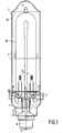
- the low-pressure sodium discharge lamp has an evacuated, tubular glass outer bulb 1 which is closed in a gastight manner and which has a first end portion 2 where a glass stemtube 3 enters the outer bulb.
- the stemtube has a pinch seal 4 inside the outer bulb.
- the first end portion 2 supports a lamp cap 5 provided with contacts 6.
- the outer bulb has a second end portion 7 with a dome shape.
- the lamp has a glass discharge tube 10 bent into a U-shape with end portions each closed in a gastight manner by means of a pinch 11.
- a current conductor 12 extends through each pinch to an electrode 13 arranged in the relevant end portion.
- the discharge tube is filled with sodium and rare gas.
- Electrical conductors 8 extend each from a contact 6 of the lamp cap 5 through the pinch seal 4 so as to be connected to a respective current conductor 12.
- a second centring member 30 for the discharge tube is present in the second end portion 7 of the outer bulb.
- the outer bulb has a heat-reflecting, light-transmitting coating at its inside, for example of tin-doped indium oxide.
- the mica plate 20 (see also Fig. 2) has projecting teeth 22 at its periphery, bent towards the lamp cap 5 and bearing on the outer bulb 1 with clamping action.
- a holder 41 is mounted in the lamp, from which holder a getter is to be evaporated which deposits on the wall of the outer bulb as a film and can bind gases such as water and hydrogen.
- the lamp is shown in its stage of manufacture in which the getter has not yet been evaporated, for example, through inductive heating.
- the outer bulb is fused to the stemtube in a vertical position in which the second end portion points upwards.
- the discharge tube, the stemtube, the second centring member, and the mica plate are held in place in the outer bulb exclusively owing to the teeth of the mica plate during this.
- the mica plate 20 shown (see Fig. 2) has teeth 22, as does its modification 20' in Fig. 3, at its periphery in a first 23 and an opposed third sector 24 of the plate, and has an unindented periphery in a second 25 and an opposed fourth sector 26 which lie between the first and third sectors.
- the electrical conductors 8 extend through respective openings 27 in the mica plate 20, are bent around the periphery, and extend to respective current conductors 12.
- the plate 20 has recesses 28 in its outer edge in which respective electrical conductors 8 are accommodated.
- the pinch seal 4 of the stemtube 3 is in contact with the mica plate 20.
- the discharge tube 10 has a tipped exhaust tube 14 which is directed at the second end portion 7 of the outer bulb 1, and the second centring member 30 is a mica plate (see Fig. 4) with an opening 31 in which said tipped exhaust tube 14 is accommodated.
- the second centring member 30 rests against the outer bulb 1 in the longitudinal direction thereof.
- An additional component 40 of the lamp (see Fig. 2) is clamped in in an opening 29 in the first centring member.
- This is a porous ceramic rod in the Figure, impregnated with platinum for decomposing hydrocarbons such as methane.
Landscapes
- Vessels And Coating Films For Discharge Lamps (AREA)
- Discharge Lamp (AREA)
Abstract
Claims (7)
- Lampe à décharge dans la vapeur de sodium à basse pression muniecaractérisée en ce que la plaque en mica (20) présente à sa périphérie des dents saillantes (22) qui sont courbées vers le culot de lampe (5) et qui s'appuient de façon serrante sur l'ampoule extérieure (1).d'une ampoule extérieure en verre tubulaire évacuée (1) qui est fermée d'une manière étanche au gazcomportant une première partie terminale (2) où un tube à rebord en verre (3) pénètre dans l'ampoule extérieure, présentant à l'intérieur de l'ampoule extérieure un scellement fermé par pincement (4), ladite partie terminale (2) appuyant un culot de lampe (5) muni de contacts (6), etcomportant une deuxième partie terminale (7) présentant la forme d'un dôme;d'un tube à décharge en verre (10) courbé en forme d'un U présentant des parties terminales qui sont fermées chacune d'une manière étanche au gaz et chacune présentant un pincement (11) à travers lequel un propre conducteur de courant (12) s'étend vers une électrode (13) disposée dans la partie terminale en question, ledit tube à décharge étant rempli de sodium et de gaz rare;de conducteurs électriques (8) qui s'étendent chacun à partir d'un propre contact (6) du culot de lampe (5) à travers le scellement fermé par pincement (4) de manière à être reliés à un propre conducteur de courant (12);d'une plaque en mica sensiblement plane (20) présentant des ouvertures (21), un propre pincement (11) traversant chacune d'elles, constituant un premier élément de centrage qui maintient le tube à décharge (10) centré dans l'ampoule extérieure (1) et un deuxième élément de centrage (30) pour le tube à décharge dans la deuxième partie terminale (7) de l'ampoule extérieure,
- Lampe à décharge dans la vapeur de sodium à basse pression selon la revendication 1, caractérisée en ce que la plaque en mica (20) présente à sa périphérie les dents saillantes (22) dans un premier (23) et dans un troisième secteur opposé (24) de la plaque, et en ce qu'elle présente un bord extérieur non denté dans un deuxième (25) et dans un quatrième secteur opposé (26) se situant entre les premier et troisième secteurs.
- Lampe à décharge dans la vapeur de sodium à basse pression selon la revendication 1 ou 2, caractérisée en ce que les conducteurs électriques (8) traversent chacun une propre ouverture (27) prévue dans la plaque en mica (20) et en ce qu'ils s'étendent, courbés autour du bord extérieur, vers un propre conducteur de courant (12).
- Lampe à décharge dans la vapeur de sodium à basse pression selon la revendication 3, caractérisée en ce que la plaque (20) présente à sa circonférence des évidements (28), chacun incorporant un propre conducteur électrique (8).
- Lampe à décharge dans la vapeur de sodium à basse pression selon la revendication 1, 2 ou 3, caractérisée en ce que le scellement fermé par pincement (4) du tube à rebord (3) est en contact avec la plaque en mica (20).
- Lampe à décharge dans la vapeur de sodium à basse pression selon la revendication 1, 2, 3 ou 5, caractérisée en ce que le tube à décharge (10) présente un queusot scellé et coupé par fusion (14) qui est dirigé vers la deuxième partie terminale (7) de l'ampoule extérieure (1), alors que le deuxième élément de centrage (30) est une plaque en mica présentant une ouverture (31) dans laquelle est incorporé ledit queusot scellé et coupé par fusion (14), ledit deuxième élément de centrage (30) s'appuyant contre l'ampoule extérieure (1) dans la direction longitudinale de celle-ci.
- Lampe à décharge dans la vapeur de sodium à basse pression selon la revendication 6, caractérisée en ce qu'un composant additionnel (40) de la lampe est fixé de façon serrante dans une ouverture (29) prévue dans le premier élément de centrage.
Priority Applications (1)
| Application Number | Priority Date | Filing Date | Title |
|---|---|---|---|
| EP95919596A EP0714552B1 (fr) | 1994-06-22 | 1995-06-12 | Lampe a decharge a vapeur de sodium basse pression |
Applications Claiming Priority (4)
| Application Number | Priority Date | Filing Date | Title |
|---|---|---|---|
| EP94201783 | 1994-06-22 | ||
| EP94201783 | 1994-06-22 | ||
| EP95919596A EP0714552B1 (fr) | 1994-06-22 | 1995-06-12 | Lampe a decharge a vapeur de sodium basse pression |
| PCT/IB1995/000460 WO1995035579A1 (fr) | 1994-06-22 | 1995-06-12 | Lampe a decharge a vapeur de sodium basse pression |
Publications (2)
| Publication Number | Publication Date |
|---|---|
| EP0714552A1 EP0714552A1 (fr) | 1996-06-05 |
| EP0714552B1 true EP0714552B1 (fr) | 1998-01-28 |
Family
ID=8216975
Family Applications (1)
| Application Number | Title | Priority Date | Filing Date |
|---|---|---|---|
| EP95919596A Expired - Lifetime EP0714552B1 (fr) | 1994-06-22 | 1995-06-12 | Lampe a decharge a vapeur de sodium basse pression |
Country Status (6)
| Country | Link |
|---|---|
| US (1) | US5619090A (fr) |
| EP (1) | EP0714552B1 (fr) |
| JP (1) | JPH09502300A (fr) |
| CN (1) | CN1089482C (fr) |
| DE (1) | DE69501543T2 (fr) |
| WO (1) | WO1995035579A1 (fr) |
Families Citing this family (4)
| Publication number | Priority date | Publication date | Assignee | Title |
|---|---|---|---|---|
| JP3858317B2 (ja) * | 1996-11-29 | 2006-12-13 | 東芝ライテック株式会社 | 放電灯点灯装置及び照明装置 |
| US6731071B2 (en) * | 1999-06-21 | 2004-05-04 | Access Business Group International Llc | Inductively powered lamp assembly |
| EP2141730A3 (fr) | 2008-07-04 | 2012-07-04 | Iwasaki Electric Co., Ltd | Lampe avec support d'ampoule interne |
| KR101175640B1 (ko) * | 2009-07-30 | 2012-08-24 | 삼이홀딩스 주식회사 | 나트륨 전등 및 그 제조방법 |
Family Cites Families (2)
| Publication number | Priority date | Publication date | Assignee | Title |
|---|---|---|---|---|
| GB865928A (en) * | 1958-12-17 | 1961-04-26 | Gen Electric Co Ltd | Improvements in or relating to sodium vapour electric discharge lamps |
| CN1004667B (zh) * | 1985-02-15 | 1989-06-28 | 菲利浦光灯制造公司 | 低压钠放电灯 |
-
1995
- 1995-06-12 CN CN95190660A patent/CN1089482C/zh not_active Expired - Fee Related
- 1995-06-12 WO PCT/IB1995/000460 patent/WO1995035579A1/fr not_active Ceased
- 1995-06-12 EP EP95919596A patent/EP0714552B1/fr not_active Expired - Lifetime
- 1995-06-12 JP JP8501883A patent/JPH09502300A/ja not_active Ceased
- 1995-06-12 DE DE69501543T patent/DE69501543T2/de not_active Expired - Fee Related
- 1995-06-19 US US08/491,752 patent/US5619090A/en not_active Expired - Fee Related
Also Published As
| Publication number | Publication date |
|---|---|
| DE69501543D1 (de) | 1998-03-05 |
| EP0714552A1 (fr) | 1996-06-05 |
| WO1995035579A1 (fr) | 1995-12-28 |
| US5619090A (en) | 1997-04-08 |
| CN1130957A (zh) | 1996-09-11 |
| DE69501543T2 (de) | 1998-07-30 |
| JPH09502300A (ja) | 1997-03-04 |
| CN1089482C (zh) | 2002-08-21 |
Similar Documents
| Publication | Publication Date | Title |
|---|---|---|
| JP2000277052A (ja) | 口金付高圧放電ランプ | |
| US5250872A (en) | Discharge lamp unit having improved discharge tube mount | |
| US6249077B1 (en) | Arc tube, mounting member and electric lamp assembly | |
| KR100371018B1 (ko) | 저압방전램프 | |
| JPH02230655A (ja) | ランプ | |
| EP0714552B1 (fr) | Lampe a decharge a vapeur de sodium basse pression | |
| US7221098B2 (en) | Electric lamp with outer bulb and associated support body | |
| JPH07153431A (ja) | 高圧放電ランプ | |
| EP0767968A2 (fr) | Lampe electrique coiffee | |
| EP0715338B1 (fr) | Lampe à décharge pour produire un rayonnement et procédé de fabrication d'une telle lampe à décharge | |
| JPS60160556A (ja) | 合成物質のランプキヤツプを有するランプ | |
| CN101124653B (zh) | 放电灯 | |
| US6586878B1 (en) | Metal halide lamp with improved getter orientation | |
| US20050029918A1 (en) | Electric lamp and manufacturing method | |
| JPH03196480A (ja) | 両端型タングステンハロゲンランプ用の耐振取付構造体 | |
| WO2002001601A1 (fr) | Lampe incandescente a halogene a branche de filament fixee dans un joint comprime | |
| US5757134A (en) | Mica heat shield for high intensity discharge lamp | |
| US20040178715A1 (en) | Arc tube/shroud holder for hid lamp | |
| US5001384A (en) | Electric gas discharge lamp including an outer envelope and supporting frame | |
| EP0410511A1 (fr) | Lampe électrique | |
| EP0599581B1 (fr) | Source d'amorçage et son procédé de fabrication | |
| JPH0328776B2 (fr) | ||
| CA2710682C (fr) | Lampe a reflexion parabolique | |
| CA2470032A1 (fr) | Lampe electrique avec ampoule exterieure et support connexe | |
| JPH02288060A (ja) | 片口金偏平放電管 |
Legal Events
| Date | Code | Title | Description |
|---|---|---|---|
| PUAI | Public reference made under article 153(3) epc to a published international application that has entered the european phase |
Free format text: ORIGINAL CODE: 0009012 |
|
| AK | Designated contracting states |
Kind code of ref document: A1 Designated state(s): BE DE FR GB |
|
| 17P | Request for examination filed |
Effective date: 19960628 |
|
| GRAG | Despatch of communication of intention to grant |
Free format text: ORIGINAL CODE: EPIDOS AGRA |
|
| 17Q | First examination report despatched |
Effective date: 19970321 |
|
| GRAG | Despatch of communication of intention to grant |
Free format text: ORIGINAL CODE: EPIDOS AGRA |
|
| GRAH | Despatch of communication of intention to grant a patent |
Free format text: ORIGINAL CODE: EPIDOS IGRA |
|
| GRAH | Despatch of communication of intention to grant a patent |
Free format text: ORIGINAL CODE: EPIDOS IGRA |
|
| GRAA | (expected) grant |
Free format text: ORIGINAL CODE: 0009210 |
|
| AK | Designated contracting states |
Kind code of ref document: B1 Designated state(s): BE DE FR GB |
|
| REF | Corresponds to: |
Ref document number: 69501543 Country of ref document: DE Date of ref document: 19980305 |
|
| ET | Fr: translation filed | ||
| RAP4 | Party data changed (patent owner data changed or rights of a patent transferred) |
Owner name: KONINKLIJKE PHILIPS ELECTRONICS N.V. |
|
| REG | Reference to a national code |
Ref country code: FR Ref legal event code: CD |
|
| PLBE | No opposition filed within time limit |
Free format text: ORIGINAL CODE: 0009261 |
|
| STAA | Information on the status of an ep patent application or granted ep patent |
Free format text: STATUS: NO OPPOSITION FILED WITHIN TIME LIMIT |
|
| 26N | No opposition filed | ||
| PGFP | Annual fee paid to national office [announced via postgrant information from national office to epo] |
Ref country code: BE Payment date: 20010614 Year of fee payment: 7 |
|
| REG | Reference to a national code |
Ref country code: GB Ref legal event code: IF02 |
|
| PG25 | Lapsed in a contracting state [announced via postgrant information from national office to epo] |
Ref country code: BE Free format text: LAPSE BECAUSE OF NON-PAYMENT OF DUE FEES Effective date: 20020630 |
|
| REG | Reference to a national code |
Ref country code: GB Ref legal event code: 746 Effective date: 20021111 |
|
| BERE | Be: lapsed |
Owner name: *KONINKLIJKE PHILIPS ELECTRONICS N.V. Effective date: 20020630 |
|
| PGFP | Annual fee paid to national office [announced via postgrant information from national office to epo] |
Ref country code: FR Payment date: 20030625 Year of fee payment: 9 |
|
| PGFP | Annual fee paid to national office [announced via postgrant information from national office to epo] |
Ref country code: GB Payment date: 20030627 Year of fee payment: 9 |
|
| PGFP | Annual fee paid to national office [announced via postgrant information from national office to epo] |
Ref country code: DE Payment date: 20030818 Year of fee payment: 9 |
|
| PG25 | Lapsed in a contracting state [announced via postgrant information from national office to epo] |
Ref country code: GB Free format text: LAPSE BECAUSE OF NON-PAYMENT OF DUE FEES Effective date: 20040612 |
|
| PG25 | Lapsed in a contracting state [announced via postgrant information from national office to epo] |
Ref country code: DE Free format text: LAPSE BECAUSE OF NON-PAYMENT OF DUE FEES Effective date: 20050101 |
|
| GBPC | Gb: european patent ceased through non-payment of renewal fee |
Effective date: 20040612 |
|
| PG25 | Lapsed in a contracting state [announced via postgrant information from national office to epo] |
Ref country code: FR Free format text: LAPSE BECAUSE OF NON-PAYMENT OF DUE FEES Effective date: 20050228 |
|
| REG | Reference to a national code |
Ref country code: FR Ref legal event code: ST |