EP0714263B1 - Kleidungsstück mit atemüberwachungsvorrichtung - Google Patents
Kleidungsstück mit atemüberwachungsvorrichtung Download PDFInfo
- Publication number
- EP0714263B1 EP0714263B1 EP94925796A EP94925796A EP0714263B1 EP 0714263 B1 EP0714263 B1 EP 0714263B1 EP 94925796 A EP94925796 A EP 94925796A EP 94925796 A EP94925796 A EP 94925796A EP 0714263 B1 EP0714263 B1 EP 0714263B1
- Authority
- EP
- European Patent Office
- Prior art keywords
- monitor
- breathing
- user
- article
- wearing apparel
- Prior art date
- Legal status (The legal status is an assumption and is not a legal conclusion. Google has not performed a legal analysis and makes no representation as to the accuracy of the status listed.)
- Expired - Lifetime
Links
- 230000029058 respiratory gaseous exchange Effects 0.000 title claims abstract description 92
- 210000000779 thoracic wall Anatomy 0.000 claims abstract description 23
- 210000000038 chest Anatomy 0.000 claims abstract description 9
- 230000008602 contraction Effects 0.000 claims abstract description 9
- 238000012544 monitoring process Methods 0.000 claims description 14
- 230000004044 response Effects 0.000 claims description 4
- 238000004891 communication Methods 0.000 claims description 2
- 230000033001 locomotion Effects 0.000 abstract description 11
- 208000008784 apnea Diseases 0.000 abstract description 7
- 208000034972 Sudden Infant Death Diseases 0.000 abstract description 5
- 206010042440 Sudden infant death syndrome Diseases 0.000 abstract description 5
- 238000000034 method Methods 0.000 abstract description 5
- 210000001015 abdomen Anatomy 0.000 abstract 2
- 210000004072 lung Anatomy 0.000 abstract 1
- 230000006870 function Effects 0.000 description 8
- 238000012545 processing Methods 0.000 description 7
- 238000010276 construction Methods 0.000 description 5
- 230000000694 effects Effects 0.000 description 5
- 230000006378 damage Effects 0.000 description 4
- 239000004744 fabric Substances 0.000 description 4
- 230000035945 sensitivity Effects 0.000 description 4
- 208000027418 Wounds and injury Diseases 0.000 description 3
- 230000002159 abnormal effect Effects 0.000 description 3
- 238000001514 detection method Methods 0.000 description 3
- 208000014674 injury Diseases 0.000 description 3
- 230000007246 mechanism Effects 0.000 description 3
- 230000000737 periodic effect Effects 0.000 description 3
- CURLTUGMZLYLDI-UHFFFAOYSA-N Carbon dioxide Chemical compound O=C=O CURLTUGMZLYLDI-UHFFFAOYSA-N 0.000 description 2
- 239000004020 conductor Substances 0.000 description 2
- 239000013078 crystal Substances 0.000 description 2
- 230000009977 dual effect Effects 0.000 description 2
- 230000000977 initiatory effect Effects 0.000 description 2
- 239000000463 material Substances 0.000 description 2
- 230000013011 mating Effects 0.000 description 2
- 230000000241 respiratory effect Effects 0.000 description 2
- 230000001953 sensory effect Effects 0.000 description 2
- 206010003497 Asphyxia Diseases 0.000 description 1
- 206010003591 Ataxia Diseases 0.000 description 1
- 208000003174 Brain Neoplasms Diseases 0.000 description 1
- 206010006322 Breath holding Diseases 0.000 description 1
- 206010010904 Convulsion Diseases 0.000 description 1
- 206010010947 Coordination abnormal Diseases 0.000 description 1
- 206010011469 Crying Diseases 0.000 description 1
- 230000005856 abnormality Effects 0.000 description 1
- 230000003213 activating effect Effects 0.000 description 1
- 230000004913 activation Effects 0.000 description 1
- 230000003321 amplification Effects 0.000 description 1
- 238000004458 analytical method Methods 0.000 description 1
- QVGXLLKOCUKJST-UHFFFAOYSA-N atomic oxygen Chemical compound [O] QVGXLLKOCUKJST-UHFFFAOYSA-N 0.000 description 1
- 208000024760 breath-holding Spells Diseases 0.000 description 1
- 229910002092 carbon dioxide Inorganic materials 0.000 description 1
- 239000001569 carbon dioxide Substances 0.000 description 1
- 210000003169 central nervous system Anatomy 0.000 description 1
- 230000008859 change Effects 0.000 description 1
- 208000016252 change in skin color Diseases 0.000 description 1
- 230000036461 convulsion Effects 0.000 description 1
- 230000003247 decreasing effect Effects 0.000 description 1
- 230000007547 defect Effects 0.000 description 1
- 238000010586 diagram Methods 0.000 description 1
- 208000037265 diseases, disorders, signs and symptoms Diseases 0.000 description 1
- 208000035475 disorder Diseases 0.000 description 1
- 239000013013 elastic material Substances 0.000 description 1
- 230000005672 electromagnetic field Effects 0.000 description 1
- 239000011532 electronic conductor Substances 0.000 description 1
- 239000007789 gas Substances 0.000 description 1
- 208000019622 heart disease Diseases 0.000 description 1
- 208000016290 incoordination Diseases 0.000 description 1
- 208000015181 infectious disease Diseases 0.000 description 1
- 230000002452 interceptive effect Effects 0.000 description 1
- 239000010985 leather Substances 0.000 description 1
- 210000002569 neuron Anatomy 0.000 description 1
- 238000003199 nucleic acid amplification method Methods 0.000 description 1
- 229910052760 oxygen Inorganic materials 0.000 description 1
- 239000001301 oxygen Substances 0.000 description 1
- 230000035935 pregnancy Effects 0.000 description 1
- 230000011514 reflex Effects 0.000 description 1
- 230000035939 shock Effects 0.000 description 1
- 231100000075 skin burn Toxicity 0.000 description 1
- 239000000126 substance Substances 0.000 description 1
- 208000011580 syndromic disease Diseases 0.000 description 1
- 238000012546 transfer Methods 0.000 description 1
- 230000001052 transient effect Effects 0.000 description 1
- 230000001960 triggered effect Effects 0.000 description 1
- 238000009423 ventilation Methods 0.000 description 1
Images


Classifications
-
- A—HUMAN NECESSITIES
- A61—MEDICAL OR VETERINARY SCIENCE; HYGIENE
- A61B—DIAGNOSIS; SURGERY; IDENTIFICATION
- A61B5/00—Measuring for diagnostic purposes; Identification of persons
- A61B5/68—Arrangements of detecting, measuring or recording means, e.g. sensors, in relation to patient
- A61B5/6801—Arrangements of detecting, measuring or recording means, e.g. sensors, in relation to patient specially adapted to be attached to or worn on the body surface
- A61B5/6802—Sensor mounted on worn items
- A61B5/6804—Garments; Clothes
- A61B5/6805—Vests, e.g. shirts or gowns
-
- A—HUMAN NECESSITIES
- A61—MEDICAL OR VETERINARY SCIENCE; HYGIENE
- A61B—DIAGNOSIS; SURGERY; IDENTIFICATION
- A61B5/00—Measuring for diagnostic purposes; Identification of persons
- A61B5/103—Measuring devices for testing the shape, pattern, colour, size or movement of the body or parts thereof, for diagnostic purposes
- A61B5/11—Measuring movement of the entire body or parts thereof, e.g. head or hand tremor or mobility of a limb
- A61B5/113—Measuring movement of the entire body or parts thereof, e.g. head or hand tremor or mobility of a limb occurring during breathing
- A61B5/1135—Measuring movement of the entire body or parts thereof, e.g. head or hand tremor or mobility of a limb occurring during breathing by monitoring thoracic expansion
Definitions
- This invention relates in general to certain new and useful improvements in breathing monitor articles of wearing apparel and more particularly, to an article of wearing apparel which is constructed so as to detect and generate an alarm signal when there is a cessation of breathing of the child user for a minimum pre-determined time period.
- SIDS sudden infant death
- the control of breathing in infants is determined by the sensitivity of various chemical and physical receptors in the human body to gas and pressures in the body. Sensitivity to oxygen and carbon dioxide in newborn children may be reduced if they do not attain a certain level of grown maturity during gestation and in the first year of their life. Thus, in many cases, these newborn children may experience breathing cessation for ten to fifteen seconds, followed by the condition of apnea for five to ten seconds without a change in skin color or heart rate. As a result, it may be difficult to detect breathing cessation in small children.
- apnea in infancy causes of apnea in infancy include gastroesophageal reflex, pharyngeal incoordination, convulsion, heart disease, infection, CNS abnormality, accidental smothering and breath-holding spells. In each of these cases, external conditions are not immediately apparent and thus, an attendant or parent of the child may not recognize cessation of breathing.
- a scope is used with leads placed on the child's chest and where the scope is connected to an overhead panel.
- an electrical signal representative of a breathing pattern
- a beeper, or other alarm device may be connected to the scope for audibly generating a signal of heart rate and/or apnea representing an emergency condition. If the frequency on the scope is beyond a certain range which would constitute a normal breathing range, then an alarm will be generated.
- this type of equipment obviously is not portable and can only be used by highly trained personnel. Moreover, it is not adapted for home-use environment and is also exceedingly expensive. As a result, this type of equipment is not effective in detecting conditions of apnea, or to reduce the incidence of sudden infant death syndrome in other than a hospital or clinical environment.
- a device which utilizes sonar waves is attached to the infant's crib and effectively listens for breath sounds.
- An elastic sheet coupled with an electrode has been used to monitor breathing activity of a child.
- this type of device requires a jacket tightly disposed about the chest-wall of the infant child. As a result, it is very uncomfortable and ironically, even militates against the condition it is attempting to monitor in that it actually restricts breathing.
- the aforesaid device has also been provided with a shock-type treatment, such that a mild electric shock is applied to the infant child if breathing does not occur for a predetermined period of time.
- this device also has severe drawbacks in that the shock, itself, is distressing to the infant child user and can cause skin burns to the infant child, not to mention the psychological damage which could be created.
- An article of wearing apparel according to the preamble of claim 1 is known from document GB-A-2 261 290.
- Belt based systems are known for example from documents EP-A 0 200 061, US-A-4 296 757 and US-A-4 696 307.
- an article of wearing apparel having the capability of detecting cessation of breathing in a user for a predetermined minimum period of time and generating an alarm signal
- said article comprising a chest encircling garment adapted to extend around the chest wall of the user, said garment having an exterior pocket, a sensor for monitoring breathing of the user, and a monitor disposed in said exterior pocket and connected to the sensor, the monitor including timing means connected to receive the signal from said sensor for determining if a time period between chest wall expansions exceeds a predetermined time limit to thereby enable monitoring of the breathing condition of the user, and an alarm signal generating means for generating an alarm signal when said time period between chest wall expansions exceeds said predetermined time limit, characterised in that said article further comprises:
- a preferred embodiment comprises an article of wearing apparel which has the capability of detecting cessation of breathing in a child user for a predetermined minimum time period and which generates an alarm signal if breathing cessation occurs for that minimum time period.
- the article of wearing apparel is designed for use about the chest region of a child. Any article which has a portion extending about a portion of the middle or upper torso of the child user can be employed.
- the article of wearing apparel which is capable of monitoring breathing conditions, is highly effective for use with infant child users, particularly newborns.
- this device can be used with children and adults of many years, and particularly with children and elderly who experience breathing conditions resulting from some physiological disorder.
- the apparatus and method of the present invention are not so limited, they are highly effective in enabling the monitoring of any breathing cessation for a period of time which could result in serious injury, if not death, of a child user.
- the article of wearing apparel of the present invention comprises a chest-encircling garment to extend around the chest-wall of the child user.
- a belt is associated with this garment for disposition around a portion of the chest-wall of the child user and encircles a portion of that chest-wall.
- a strain gauge is associated with the belt and is capable of detecting chest-wall expansion and contraction and generating a signal in connection therewith.
- the article of wearing apparel comprises a monitor which includes a timing means and an alarm signal generating means.
- the timing means is connected to receive the signals from the gauge means and determines if there is a minimum time period elapse between chest-wall expansion, that is, a lack of breathing for a period which would exceed a minimum predetermined time period.
- the alarm signal generating means generates an alarm signal if the time period between the chest-wall expansions exceeds this predetermined time limit and thereby enables a monitoring condition.
- the article of wearing apparel comprising a chest-encircling garment as, for example, a shirt, extends fully around the upper torso of the child user.
- the elastic belt should extend fully around, or at least around a substantial portion of the middle or upper torso of the child user.
- the shirt or a similar garment, has a pocket on the external surface which holds a monitor and this monitor includes the timing means and the signal generating means, as aforesaid.
- the belt for this purpose, is an elastic belt. In this way if the strain gauge is mounted on the surface of the belt, the belt will operate as type of amplifier to amplify the actual chest wall expansion and contraction.
- the article of wearing apparel is preferably constructed so that the monitor is located close to the armpit of the child user and is essentially located under the armpit of the child user. In this way, it has been found that the monitor is relatively unobtrusive and does not interfere with normal movement of the child user.
- the present invention can also be considered to be an assembly of a type which is used for monitoring the condition of apnea in a child user, but which also relies upon the use of an article of wearing apparel and a monitor associated with that article of wearing apparel.
- the monitor operates in the manner as previously described and the article of wearing apparel may be any article, as also previously described.
- the monitor used in this assembly is also effective in that it is programmed to cause generation of a warning signal from the assembly if it is not put in a condition of proper use when disposed on the child user.
- the monitor is designed to generate a signal indicative of proper disposition on a child user when the article has been properly located on a child user.
- a warning signal may be generated if the assembly becomes inoperative while being worn by a child user. In this way, the device of the present invention is quite safe for use.
- the described apparatus also provides a unique electrical circuit arrangement for operation of an article of wearing apparel which is disposed about a child user, and monitors a condition of apnea in the child user.
- This electrical circuit arrangement comprises a sensing means for detecting a condition where no breathing has occurred in a minimum predetermined time interval.
- a processing unit receives the electrical signals from the sensing means in response to breathing activity by a child user.
- a timing means is provided for generating timing signals to compare against electrical signals from the processing unit.
- a comparator means compares the electrical signals with timing signals from the timing means to determine if the electrical signals representing breathing activity occurred within this mean minimum predetermined time period. If the comparator means determines that the signals did not occur in the predetermined time period, then an alarm is energized for initiating an audible or visible alarm.
- the device of the present invention may be fully adjustable to conform to the size of the child user. It may also be made with fashionable detail and appliques, as desired. Further, all of the electronic components are hidden within a pocket in the shirt and therefore, does not detract from the aesthetic quality which may be built into the article of wearing apparel.
- the detection system of the invention has a power-on automatic clearing mechanism. It also is provided with a ready-check monitoring operation.
- a flash indicator signals a continuous steady state operation so that a user knows that the system is operating properly.
- the system is effective in counting motion frequency so that an alarm may be triggered if the frequency falls below a certain frequency period.
- the monitor of the invention is essentially fail-proof in that excessive pressure on the motion sensor activates a warning indicator. Furthermore, if the belt which holds the gauge should become loosened, a warning signal is also generated.
- the device is battery operated, but requires very little current in operation. Consequently, the batteries have a relatively long life span when used in the device.
- the device may also include an internal low power switch and prevent monitor setting and operation and thereby alert the caretaker that batteries may need replacement.
- the device of the present invention may also be provided with other types of fail-safe alert arrangements.
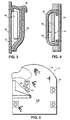
- A designates an article of wearing apparel in the form of a shirt 18 adapted to be worn about the upper and or middle torso of a child user, and particularly an infant child user.
- the shirt comprises a torso-encircling portion 20 terminating in an inner flap 22 and an overlying outer flap 24.
- the torso-covering portion 20 is provided with an upper neck-receiving region 26 and terminates in a pair of sleeve sections 28, as best shown in Figures 1 and 2.
- the shirt-like article A may be in the form of a typical undershirt, as shown in Figure 1.
- this article A can be constructed in a form of a decorative outer shirt arrangement, as shown in Figure 2, such that it will operate as a monitor and also function as an outer wearing garment.
- like reference numerals, as used in Figure 2 designate similar components in the shirt-like article of Figure 1.
- the illustration of the shirt-like article in Figure 2 is only representative of a large number of garments which could be used in the present invention.
- the shirt-like article A is also provided with a plurality of snap fasteners 30 for securing the overlying outer flap 24 to the inner flap 22, as shown in Figure 1.
- snap fasteners 30 for securing the overlying outer flap 24 to the inner flap 22, as shown in Figure 1.
- other forms of releasible fasteners could be provided, although the fasteners must be connected to and cooperate with the monitor as hereinafter described in more detail.
- the shirt 18 is formed of a fabric layer 34. Located on the interior portion of the fabric layer 34 is an inner pocket forming closure panel 35, thereby forming an interior pocket 36, as shown in Figure 4. Located on the exterior of the shirt A is a monitor-receiving pocket 37 formed by an outer pocket-receiving lining 38 and a closure flap 39. Disposed within the monitor-receiving pocket 37 is a breathing condition monitor 40 which constitutes one of the integral portions of the system of the present invention. This monitor 40 is hereinafter described in more detail. The monitor-receiving pocket 37 and the breathing condition monitor 40 is essentially located in a position where it would be close to or under the armpit of the child user. It has been found in connection with the present invention that in this position, the breathing condition monitor 40 presents the least obtrusive appearance and is also the most comfortable position of disposition on the child user.
- An elastic belt 41 which forms part of the article of wearing apparel is also adapted to extend around an exterior portion of the shirt 18 in the manner as best illustrated in both Figures 1 and 2 of the drawings.
- the elastic belt 41 may be conventionally formed of any elastic material, that is, one capable of stretching and contracting.
- the elastic belt 41 has an end 42 for manual grasping in order to release and tighten the elastic belt 41.
- the elastic belt 41 may be provided with fiber-fastening attachment strips, such as the "Velcro strips" 44 on its underside in order to enable releasible attachment.
- the actual operation of the Velcro, or other fiber-fastening attachment strips, is not illustrated in any detail herein, inasmuch as this is essentially of conventional construction.
- the elastic belt 41 is worn in a position where it is located essentially immediately beneath the monitor-receiving pocket 37, or at least in the vicinity of the monitor-receiving pocket 37. In either case, the elastic belt 41 is preferably located in the middle or upper torso portion of the child user. In this way, breathing expansion and contraction of a chest of the child user during a breathing cycle will cause an optimum concomitant expansion and retraction of the elastic belt 41. In this way, the elastic belt 41 serves as a type of mechanical force amplifier for the sensor assembly 46.
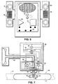
- the sensor assembly 46 is comprised of a fabric or leather pad 47 with one or more strain gauge sensors 48 mounted thereon, as also best illustrated in Figures 8 and 9 of the drawings. Further, any type of'sensor which is capable of detecting expansion and contraction of chest movement may be employed for this purpose. The details of mounting the pad 47 are hereinafter described in more detail.
- the terminal end 42 of the elastic belt can be machine stitched to the shirt itself.
- the shirt may be provided with additional snap fasteners 54, as shown in Figure 5.
- additional snap fasteners 54 could, if desired, be located within the monitor-receiving pocket 37.
- a snap conductor bus 82 ( Figure 7) which allows current flow to a sensor and monitor arrangement, when snapped or mated with a like fastener.
- This snap connector bus 82 is more fully hereinafter described in more detail.
- the snap fasteners 30, on the overlying flap 24 are similarly connected to the electrical circuitry forming part of the article of wearing apparel A.
- the snap fasteners 30 can be connected to the similar snap fasteners 54.
- the mechanism for fixing the pad 47, containing the strain gauge sensors 48, to the belt 41 is more fully illustrated in Figure 9 of the drawings.
- the pad 47 itself is provided with a pair of openings 50, as best illustrated in Figures 7 and 9 of the drawings.
- This pad 47 overlies the material forming the belt 41, as also illustrated in Figure 9.
- the openings 50 are used for securing the pad 47, containing the strain gauges 48, to the belt 41 by means of lines of stitching, as illustrated in Figure 9.
- lines of stitching 64 are generally perpendicular to a vertical center line passing through the openings 50 and particularly with respect to an edge of the openings 50. These lines of stitching 64 are effective to permit a required limited degree of movement of the pad as the belt 41 is stretched.
- the remaining lines of stitching 65 are somewhat angularly located with respect to the circumference of the opening 50, as also illustrated. This provides a degree of rigidity against complete stretching and also enables the requisite amount of stretching of the pad, if required with the belt. In this way, there is no interference with amplification of the signals to the strain gauges.
- the breathing condition monitor 40 comprises an outer housing 60 which includes the electronic components forming part of this breathing condition monitor 40.
- the breathing condition monitor 40 is operated by a pair of batteries 62, such as conventional disc-type batteries.
- the breathing condition monitor 40 is also provided with a socket at one end which is adapted for connection to a mating socket connected to the sensor assembly 46, as also best illustrated in Figures 6 and 7 of the drawings.
- signals which are generated at the strain gauges 48 will be transmitted to the breathing condition monitor 40 through the bus 82.
- These signals are amplified by an A6 amplifier 68.
- the amplified signals from the A6 amplifier 68 are then introduced into a timing circuit which may be a conventional rudimentary type of timer for merely determining whether or not expansion and contraction signals, resulting from chest expansion and contraction, occurred within a predetermined time interval. If the signals generated by the strain gauge 48 did occur within that predetermined time interval, then a condition of normal breathing would be indicated. However, if the signals from the strain gauge 48 did not occur within the predetermined time interval, that would be an indication of an abnormal breathing pattern.
- the timing circuit 70 may also include a comparator circuit 72, or may otherwise operate in conjunction with a comparator circuit 72, so as to enable comparison of strain gauge signals with timing signals.
- a fairly simple and inexpensive detection circuit can be employed. If the signals generated at the strain gauge 48 did not occur within a predetermined time period, as established by the timing signals, then an alarm can be generated, as hereinafter described. Any conventional form of the timing circuit 70 may be used for this purpose, as for example, a crystal oscillator or the like.
- the timing circuit 70 and the comparator circuit 72 form part of a microprocessor 73.
- the timing circuit 70 can actually be replaced by an integrated circuit processor which would operate with a separate comparator 72 as in a more preferred embodiment of the invention.
- the integrated circuit microprocessor 73 could be capable of performing not only the timing functions and the comparison function, but to also initiate other signals, as hereinafter described. Thus, and in this respect, the microprocessor 73 would then constitute a so-called "smart" processor.
- the breathing condition monitor 40 also comprises a conventional buzzer 74 which is connected to the microprocessor 73 and is energized to generate a warning signal if an abnormal breathing pattern is detected.
- the breathing condition monitor 40 also comprises one or more light-emitting diodes 75 to indicate operation of the apparatus. In this case, a plurality of light-emitting diodes 75 could be employed, so as to indicate the state of the apparatus and any type of condition which might arise.
- the breathing condition monitor 40 also comprises a monitor switch 76 which can operate as a type of reset switch. In this way, the user of the apparatus can turn the breathing condition monitor 40 on/off at will by use of the monitor switch 76.
- the processor 73 could be programmed so as to operate upon connection of the various snap fasteners, as for example, the snap fasteners 30 in mating engagement with the corresponding snap fasteners 54.
- FIG 6 illustrates a schematic type of arrangement of the various components in the breathing condition monitor 40.
- the snap or Velcro fasteners 30 are connected to the breathing condition monitor 40, as shown.
- the breathing condition monitor 40 may be provided with various connector pins 80, as shown in Figure 6, for electrical connection to various other snap fasteners and the like.
- the various snap or Velcro fasteners 30 are connected to the breathing condition monitor 40 by means of the strap-type conductors 82 which may be mounted within or on the actual fabric material forming part of the shirt 18 or other article of wearing apparel.
- the breathing condition monitor itself may be provided with attachment strips which are releasibly attached to the garment itself.
- attachment strips which are releasibly attached to the garment itself.
- fiber-fastening strips of the type offered under the mark Velcro may be employed.
- snaps may also be employed for securing the breathing condition monitor to the garment itself.
- Figure 6 shows the use of a pair of snaps 81 which may be on the monitor itself and cooperate with similar snaps 83 on the shirt.
- Velcro straps 85 may also be employed for this purpose.
- Figure 10 illustrates in electrical schematic form the overall arrangement of the various components forming part of the breathing condition monitor 40.
- Figure 10 illustrates a sensor network 84 which actually comprises the sensory mechanism assembly 46.
- the sensory network 84 may also comprise other sensors which may form part of the apparatus, as for example, temperature sensors or the like.
- the sensor network 84 receives the positive and negative power inputs 85 and 86 from a battery source of power.
- the sensor network 84 also receives positive and negative strain gauge signals 87 and 88, respectively.
- the signals from the sensor network 84 are amplified by the operational amplifier 68, as previously described, and then introduced into the microprocessor 73.
- the microprocessor 73 comprises the individual comparator 72 and an individual timing network 70, as previously described.
- the outputs from this circuit include the monitor switch 76, the light emitting diodes 75 and the buzzer 74.
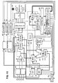
- Figure 11 of the drawings illustrates in more detail some of the electronic components which form part of the actual circuit arrangement of Figure 10.
- the sensor comprising at least the network sensor assembly 46, actually receives signals from the strain gauge sensors 48 in sensory-receiving contact with the thoracic wall of the child user and transmits these signals to the operational amplifier 68.
- the operational amplifier 68 thereupon amplifies the sensed signals and switches the microprocessor 73, sometimes referred to as the central processing unit and which is actually comprised of several of the components in Figure 11. This begins signal processing by activating an A-latch 90 and a B-latch 92, as well as an arithmetic multiplexer 98.
- the central processing unit includes several of the components and may include essentially all of the components of Figure 11, with the exception of the operational amplifier 68 and the sensor network 84, the indicator lights, e.g. the light-emitting diodes 75, and the buzzer 74, as hereinafter described.
- the microprocessor will include a register 96 such as a shift register and which has outputs directed to the A-latch 90 and the B-latch 92.
- the microprocessor 73 may also be considered to constitute or otherwise include a computer.
- the A-latch 90 receives information from the shift register 96, sequentially, and passes this information to the arithmetic multiplexer 98, on command from a main clock generator, or clocking circuit 100.
- the B-latch 92 also receives information from the shift register 96, and sequentially passes this information to a memory address register 102 on a proper-time basis, in accordance with a signal from the clock generator 100.
- the clock generator 100 may be any conventional form of clocking circuit, as, for example, a crystal oscillator-type clock circuit. In this respect, relatively simple components may be used since precise time control in the operation of the various components is not critical.
- the arithmetic multiplexer 98 has a pair of data input and one data output.
- an N-bit control selects one of the inputs from the A-latch 90 or from a main buffer register 104 and transmits this input to one limb, such as the left-hand limb, of an arithmetic logic unit 106.
- the arithmetic logic unit 106 receives information from the B-Latch 92, as shown, at its right leg and from a microinstruction register 108 and particularly, an arithmetic logic field 110 of the microinstruction register 108.
- the arithmetic logic unit 106 determines the function of the arithmetic logic unit 106 which is to be performed, such as addition, multiplication, etc.
- the arithmetic logic unit 106 also has two control inputs which can set the arithmetic logic unit 106 to a positive or a negative state and an input from the microinstruction register 108 which sets the arithmetic logic unit 106 to a zero state.
- a shifter 112 which is effectively a 16-bit arithmetic circuit, receives parallel data from the arithmetic logic unit 106 on an input line 113 and which actually constitutes a plurality of individual input lines 113.
- the shifter 112 will effectively shift one data bit to the right or left, depending upon the signal from an SH field of the microinstruction register 108. Then the data therefrom is transmitted to and stored in the memory buffer register 104.
- the memory address register 102 drives the addresses from the B-latch 92 to the comparator 72 for analysis.
- the memory buffer register 104 drives the data received from the shifter 112 to the comparator 72 and to the arithmetic multiplexer 98.
- the circuit includes a C-latch 117 which switches on the appropriate indicator when information from the thoracic wall of the child user and the breathing condition monitoring system 40 is interrupted. In other words, when information at the processing unit'(hereinafter described) does not compare with incoming data, the C-latch 117 is initiated.
- the circuit further comprises a D-latch 118 which is, in effect, a combination circuit that receives information from the RD and WR fields of the microinstruction register 108, as shown, in order stabilize the operational amplifier 68.
- the shift register 96 is a logic circuit which functions as a type of storage unit, as aforesaid. This shift register 96 will enable the recording of a 16-bit word from any of the appropriate decoders, including an A-decoder 120, a B-decoder 122, and a C-decoder 124 at the appropriate time, based on signals from the sensor network 84. At the appropriate subcycle, the shift register 96 will thereupon be clocked to transmit information to the memory address register 102 through the B-latch 92.
- this clocking circuit 100 actually functions as a type of computer system drive.
- the clocking circuit 100 emits periodic sequences of pulses which define the cycles of operation. During each cycle, execution of an instruction from the microinstruction register 108 can occur.
- the clocking circuit 100 has four outputs, and one of which is a primary output and the other three which are derived from the primary output.
- timing subcycles there are several timing subcycles in the operation of the breathing condition monitor 40.
- first subcycle that is, subcycle 1
- information is loaded into the microinstruction register 108 to be executed.
- information stored in register 96 is gated onto the A-latch 90 and the B-latch 92.
- third subcycle inputs to the circuit are stabilized and transmitted to the arithmetic logic unit 106 and the shifter 112 producing a stable output which may also be loaded into the memory address register 102.
- the output of the shifter 112 is stabilized and loaded into the main buffer register 104.
- the circuit may include sequential control logic, if desired, having outputs which determine the operation of the microinstruction register 108. This logic may actually form part of and be included within the microinstruction register 108.
- the arithmetic logic unit 106 output signals are received at the shifter 112.
- an output .from the microinstruction register 108 controls a sequential multiplexer 126 having a primary function to route information and, in this case, to route information to the microprogram controller 130.
- the latter controller 130 is, in turn, controlled by the ADDR field of the microinstruction register 108.
- the microprocessor control unit 128 causes an information transfer directly to the microinstruction register 108.
- circuit could also include a separate microprocessor, counter 130 designated as "MPC" in Figure 11.
- MPC microprocessor counter 130
- the microprocessor counter 130 could, if desired, be incorporated one or more of the other components in Figure 11.
- the microinstruction register 108 is effectively a memory and main control register which enables driving of data to control the other components, as heretofore described.
- the microinstruction register 108 actually includes thirteen fields which correspond to components of the circuit, or various bus lines. Certain of these fields are hereinafter described.
- the microinstruction register 108 includes an AMUX field, which outputs information on a data output bus line of the microinstruction register 108 controls the arithmetic multiplexer 98.
- a condition field (COND) constitutes a data output of the microinstruction register 108 which determines whether or not the next microinstruction is derived from the MPC + 1 field or the ADDR field.
- An arithmetic logic field (ALU field) constitutes a data output of the microinstruction register 108 which controls the arithmetic logic unit 106.
- the shift field (SH field) constitutes a data output of the microinstruction register 108 which controls the shifter 112.
- the main address register field (MAR field) is a data output of the microinstruction register 108 which controls the memory address register 102.
- the main buffer register 104 field (MBR field) is a data output of the microinstruction register 108 which controls the main buffer register 104.
- the microinstruction register 108 also includes an RD field which constitutes an output controlling the D-latch 118 and the main buffer register 104.
- a WR field of the microinstruction register 108 also controls the D-latch 118 and the main buffer register 104.
- An ENA field constitutes a data output of the microinstruction register 108 which controls the A-decoder 120.
- a C-decoder field constitutes a data output bus line of the microinstruction register 108 which controls the C-decoder 124.
- a B-decoder constitutes an output of the microinstruction register 108 which controls the B-decoder 122.
- An A-decoder field constitutes a data output of the microinstruction register 108 which controls the A-decoder 120.
- An ADDR field of the microinstruction register 108 constitutes an output which sends address messages to the arithmetic multiplexer 130.
- the microprocessor counter 130 actually operates in conjunction with the microprocessor control unit 128 to literally control the microinstruction register 108 and the particular function, which is to be next executed.
- An incrementing circuit 132 is also provided for preparing for the loading of the next sequential instruction and transmits such information to the sequential multiplexer 126.
- the microprocessor control unit 128 may also operate as a type of memory for holding the microinstructions for the central processing unit.
- the sequential multiplexer 126 is actually a combination circuit that has dual data inputs received from the increment unit 132 and the microinstruction register 108 ADDR field.
- This increment circuit unit 132 is controlled by the logic circuit which governs the dual input passing through and routes it to the microprocessor control unit 128.
- the A-decoder 120 effectively constitutes a combination circuit which has input lines and output lines.
- the input lines carry information from the microinstruction register 108, and particularly the A field and the ENA field of the microinstruction register 108. If the binary number on the input line is 1, then the output line will be 1, and all other output lines will be 0.
- the B-decoder 122 is also a circuit which has n input lines and to 2n output lines. The input lines receive information from the MIRB field. If the binary number on the input is 1, then the corresponding output line will be 1 and all other output lines will be 0.
- the C-decoder 124 is a circuit which also has n input lines and 2n output lines. The input lines receive information from the MIRC field. If the binary number on a particular input line is 1, the number on the corresponding output line will be 1, and all other output lines will be 0.
- the comparator 72 receives information from the memory address register 102 and the main buffer register 104. This comparator 72 compares bits from these registers and when conditions, such as A equal B, A less than B, or A greater than B, do not compare at the appropriate time, C-latch 117 will operate for initiating the actuation of one of the indicator lights or audible alarm.
- the circuit also includes a clear switch 140 which operates to reset the clocking circuit, the latches, the registers and the control units to their initial operating state.
- the buzzer 74 is activated by the C-latch 117 and the lights 74 are also activated by the C-latch 117.
- the breathing condition monitor article is quite simple and almost fail-proof in providing automatic monitoring of breathing conditions. Essentially all that is required is to effectively dress the child user.
- the device is quite reliable and operates on a very low frequency basis. Moreover, it is designed so that it is fairly simple to use, thereby requiring minimal parental or adult education to use.
- the device effectively has a built-in motion detecting sensor.
- the elastic belt 41 may be fully adjustable and may even be provided with a tension check signal, if desired.
- the electronic conductors are essentially all flat cable and therefore, capable of being easily hidden in the garment and out of the way of the infant user. Moreover, by simple removal of the breathing condition monitor 40, the entire shirt 18 can be washed and dried.
- the shirt 18 is constructed so that when the snap fasteners 30 and 54 are initially snapped together, there is an automatic clearing of the components in the monitor. Further, there is a ready check monitoring system. An alert condition signal is generated until a tension signal, representing the connection of the elastic belt 41 is received at the breathing condition monitor 40. The processor of the monitor thereupon initiates a system check and will cause the generation of a signal which may be in the form of an audible signal that identifies to the caretaker that the monitor is correctly operating. This signal may be made by the sound generator, or any of the light-emitting diodes.
- the monitoring system operates on a continuous steady-state basis. It is effective for decoding infant motion activity.
- the breathing condition monitor 40 counts the motion frequency and is capable of generating a low-motion rate trigger sound generator.
- the entire system is essentially fail-proof. If excess pressure should be applied to the sensor assembly 46, the clear switch forming part of the monitor will activate a warning indicator, such as the buzzer or other sound generator 74. In like manner, a loosened belt will also cause activation of the sound generator 74. Further if the battery power is low, operation is precluded. This type of device which precludes actuation on low battery conditions is known in the art.
- the device is also highly effective in that it is comfortable to a child user, such as an infant. Further, it presents little or no possibility of injury to the child. It is essentially 100% reliable in detecting breathing conditions. If the child should happen to lie on the breathing condition monitor 40, this would not interfere with the operation of the apparatus.
- the breathing condition monitor 40 is provided with a manually operable clear switch such as the monitor switch 76, and this may be pressed to off-set transient spikes. If respiratory motion should cease for about 15 to 30 seconds, the sound generator 74 will be energized and will remain on until the breathing condition monitor 40 is actually reset by the caretaker. Again, if excessive pressure is applied to the breathing condition monitor 40, the sound generator 74 will be activated.
- the device of the present invention is highly effective and achieves all of the objectives which have been previously described.
Landscapes
- Health & Medical Sciences (AREA)
- Life Sciences & Earth Sciences (AREA)
- Heart & Thoracic Surgery (AREA)
- Surgery (AREA)
- Physics & Mathematics (AREA)
- Veterinary Medicine (AREA)
- Biophysics (AREA)
- Pathology (AREA)
- Engineering & Computer Science (AREA)
- Biomedical Technology (AREA)
- Public Health (AREA)
- Medical Informatics (AREA)
- Molecular Biology (AREA)
- General Health & Medical Sciences (AREA)
- Animal Behavior & Ethology (AREA)
- Oral & Maxillofacial Surgery (AREA)
- Physiology (AREA)
- Dentistry (AREA)
- Measurement Of The Respiration, Hearing Ability, Form, And Blood Characteristics Of Living Organisms (AREA)
- Measuring And Recording Apparatus For Diagnosis (AREA)
- Respiratory Apparatuses And Protective Means (AREA)
- Other Investigation Or Analysis Of Materials By Electrical Means (AREA)
- Investigating Or Analysing Biological Materials (AREA)
Claims (5)
- Bekleidungsartikel, welcher geeignet ist, das Aussetzen des Atmens eines Anwenders während eines vorbestimmten minimalen Zeitraums zu entdecken und ein Alarmsignal zu erzeugen, wobei der Artikel ein den Brustkorb umschließendes Kleidungsstück (18) umfasst, das dafür angepasst ist, die Brustwand des Anwenders zu umgeben, wobei das Kleidungsstück (18) eine äußere Tasche (37), einen Fühler (46) zum Überwachen der Atmung des Anwenders und ein Überwachungsgerät (40) umfasst, das in der äußeren Tasche (37) angebracht ist und mit dem Fühler verbunden ist, wobei das Überwachungsgerät Zeitsteuerungsmittel (70) umfasst, die angeschlossen sind, um das Signal des Fühlers zu empfangen, um zu bestimmen, ob ein Zeitraum zwischen den Brustwandausdehnungen eine vorbestimmte Zeitgrenze überschreitet und dadurch eine Überwachung des Atmungszustands des Anwenders zu ermöglichen, und ein Mittel zur Erzeugung von Alarmsignalen (74) umfasst, um ein Alarmsignal zu erzeugen, wenn der Zeitraum zwischen den Brustwandausdehnungen die vorbestimmte Zeitgrenze überschreitet, dadurch gekennzeichnet, dass der Artikel darüber hinaus umfasst:einen elastischen Gürtel (41), der mit dem Kleidungsstück (18) verbunden ist und dafür angepasst ist, einen Teil der Brustwand des Anwenders zu umschließen, wobei sich der Gürtel (41) in eine innere Tasche (35, 36) des Kleidungsstücks (18) erstreckt und in dieser inneren Tasche (35, 36) endet, wobei der Fühler (46) einen Dehnungsmesser (48) umfasst, der mit dem Gürtel verbunden ist und im Bereich der inneren Tasche (35, 36) angeordnet ist, um Ausdehnung und Kontraktion der Brustwand des Anwenders zu erfassen, und um als Reaktion darauf ein Signal zu erzeugen, wobei das Mittel zum Erzeugen eines Alarmsignals (74) in der Außentasche (37) des Kleidungsstücks (18) angeordnet ist.
- Bekleidungsartikel nach Anspruch 1, wobei der Gürtel (41) angepasst ist, um vollständig um dem mittleren oder oberen Torso eines Anwenders zu verlaufen.
- Bekleidungsartikel nach Anspruch 1, wobei der Dehnungsmesser (48) an dem elastischen Gürtel (41) angebracht ist und sich im Bereich der inneren Tasche (35, 36) befindet.
- Bekleidungsartikel nach Anspruch 1, wobei die äußere Tasche in der Nähe der Achselhöhle des Anwenders liegt, wenn das Kleidungsstück (18) von einem Anwender getragen wird.
- Bekleidungsartikel nach Anspruch 1, wobei die innere Tasche (35, 36) in Verbindung mit einer äußeren Tasche (37) steht.
Applications Claiming Priority (3)
| Application Number | Priority Date | Filing Date | Title |
|---|---|---|---|
| US106602 | 1993-08-16 | ||
| US08/106,602 US5454376A (en) | 1993-08-16 | 1993-08-16 | Breathing monitor articles of wearing apparel |
| PCT/US1994/009004 WO1995005119A2 (en) | 1993-08-16 | 1994-08-11 | Breathing monitor articles of wearing apparel |
Publications (3)
| Publication Number | Publication Date |
|---|---|
| EP0714263A1 EP0714263A1 (de) | 1996-06-05 |
| EP0714263A4 EP0714263A4 (de) | 1997-10-15 |
| EP0714263B1 true EP0714263B1 (de) | 2003-10-29 |
Family
ID=22312298
Family Applications (1)
| Application Number | Title | Priority Date | Filing Date |
|---|---|---|---|
| EP94925796A Expired - Lifetime EP0714263B1 (de) | 1993-08-16 | 1994-08-11 | Kleidungsstück mit atemüberwachungsvorrichtung |
Country Status (7)
| Country | Link |
|---|---|
| US (1) | US5454376A (de) |
| EP (1) | EP0714263B1 (de) |
| AT (1) | ATE252869T1 (de) |
| AU (1) | AU7559494A (de) |
| DE (1) | DE69433283T2 (de) |
| ES (1) | ES2210259T3 (de) |
| WO (1) | WO1995005119A2 (de) |
Cited By (1)
| Publication number | Priority date | Publication date | Assignee | Title |
|---|---|---|---|---|
| EP3369371B1 (de) * | 2017-03-02 | 2024-09-18 | Star Cooperation GmbH | Multisensordress und deren verwendung |
Families Citing this family (70)
| Publication number | Priority date | Publication date | Assignee | Title |
|---|---|---|---|---|
| US5778882A (en) * | 1995-02-24 | 1998-07-14 | Brigham And Women's Hospital | Health monitoring system |
| US5825293A (en) * | 1996-09-20 | 1998-10-20 | Ahmed; Adel A. | Apparatus and method for monitoring breathing magnetically |
| EP0996360A1 (de) * | 1997-02-05 | 2000-05-03 | Instrumentarium Corporation | Vorrichtung zum überwachen von mechanisch übertragenen signalen bezüglich der organe oder vitalfunktionen und zur verarbeitung der ergebnisse |
| AUPO785397A0 (en) * | 1997-07-11 | 1997-08-07 | Micro Monitoring Systems Pty. Ltd. | Apnoea monitor |
| US6687523B1 (en) | 1997-09-22 | 2004-02-03 | Georgia Tech Research Corp. | Fabric or garment with integrated flexible information infrastructure for monitoring vital signs of infants |
| US5993397A (en) * | 1998-01-23 | 1999-11-30 | Branson; Krista Lynn | Infant respiratory monitor |
| US6267730B1 (en) * | 1998-08-25 | 2001-07-31 | Kenneth M. Pacunas | Apnea detecting system |
| USD417333S (en) | 1998-09-17 | 1999-12-07 | Lu San Re | Pocket for attachment under the arm of a sleeveless undershirt |
| FR2789569B1 (fr) | 1999-02-11 | 2001-07-13 | Raoul Parienti | Appareil de surveillance du souffle respiratoire durant le sommeil par capteurs passifs |
| CA2405848C (en) * | 2000-04-17 | 2010-11-09 | Vivometrics, Inc. | Systems and methods for ambulatory monitoring of physiological signs |
| US6360615B1 (en) * | 2000-06-06 | 2002-03-26 | Technoskin, Llc | Wearable effect-emitting strain gauge device |
| WO2002011617A1 (fr) | 2000-08-04 | 2002-02-14 | Raoul Parienti | Appareil de surveillance du souffle respiratoire durant le sommeil par capteurs passifs |
| US20020124295A1 (en) * | 2000-10-30 | 2002-09-12 | Loel Fenwick | Clothing apparatus, carrier for a biophysical sensor, and patient alarm system |
| US6879970B2 (en) * | 2001-04-02 | 2005-04-12 | Invivodata, Inc. | Apparatus and method for prediction and management of subject compliance in clinical research |
| US8533029B2 (en) | 2001-04-02 | 2013-09-10 | Invivodata, Inc. | Clinical monitoring device with time shifting capability |
| US8065180B2 (en) * | 2001-04-02 | 2011-11-22 | invivodata®, Inc. | System for clinical trial subject compliance |
| US7873589B2 (en) | 2001-04-02 | 2011-01-18 | Invivodata, Inc. | Operation and method for prediction and management of the validity of subject reported data |
| US6450168B1 (en) | 2001-04-17 | 2002-09-17 | Kellie I. Nguyen | Infant sleeping blanket/garment for use with medical devices |
| GB2378249B (en) * | 2001-07-30 | 2005-08-31 | Grove Medical Ltd | Device for monitoring respiratory movements |
| US20030074711A1 (en) * | 2001-10-19 | 2003-04-24 | Iversen Portia E. | Pressure vest for treating autism |
| US6755795B2 (en) * | 2001-10-26 | 2004-06-29 | Koninklijke Philips Electronics N.V. | Selectively applied wearable medical sensors |
| EP1662996B1 (de) * | 2003-09-03 | 2014-11-19 | ResMed R&D Germany GmbH | Erfassungsgerät sowie verfahren zur observation schlafbezogener atmungsstörungen |
| US20050120459A1 (en) * | 2003-11-04 | 2005-06-09 | Mcconnell Michael T. | Clothing for maintaining a baby's normal body temperature |
| US20050094703A1 (en) * | 2003-11-04 | 2005-05-05 | Mcconnell Michael T. | Clothing for measuring and displaying a body temperature |
| US7299964B2 (en) * | 2004-01-15 | 2007-11-27 | Georgia Tech Research Corp. | Method and apparatus to create electrical junctions for information routing in textile structures |
| EP1731090A4 (de) | 2004-03-24 | 2009-07-29 | Dainippon Pharmaceutical Co | Kleidungsstück für die messung von biologischen informationen mit einer elektrode, system zur messung von biologischen informationen und vorrichtung zur messung von biologischen informationen und verfahren zur kontrolle der vorrichtung |
| WO2005089645A1 (ja) * | 2004-03-24 | 2005-09-29 | Dainippon Sumitomo Pharma Co., Ltd. | センサを有する生体情報計測用衣服、生体情報計測システムおよび生体情報計測装置、および装置制御方法 |
| US7833177B2 (en) * | 2006-08-29 | 2010-11-16 | Kimberly-Clark Worldwide, Inc. | Breast feeding quantification |
| US8114030B2 (en) | 2006-08-29 | 2012-02-14 | Kimberly-Clark Worldwide, Inc. | Breastfeeding quantification |
| US20080077042A1 (en) * | 2006-08-29 | 2008-03-27 | Feldkamp Joseph R | Breastfeeding Quantification |
| US20080077020A1 (en) * | 2006-09-22 | 2008-03-27 | Bam Labs, Inc. | Method and apparatus for monitoring vital signs remotely |
| US20080219319A1 (en) * | 2007-01-05 | 2008-09-11 | Jay Buckalew | Biological parameter monitoring system and method therefor |
| US20080183095A1 (en) * | 2007-01-29 | 2008-07-31 | Austin Colby R | Infant monitor |
| KR100903172B1 (ko) * | 2007-06-04 | 2009-06-17 | 충북대학교 산학협력단 | 호흡신호를 무선으로 감지하기 위한 방법 및 이를 수행하기 위한 장치 |
| US8360904B2 (en) | 2007-08-17 | 2013-01-29 | Adidas International Marketing Bv | Sports electronic training system with sport ball, and applications thereof |
| US8702430B2 (en) | 2007-08-17 | 2014-04-22 | Adidas International Marketing B.V. | Sports electronic training system, and applications thereof |
| US8221290B2 (en) | 2007-08-17 | 2012-07-17 | Adidas International Marketing B.V. | Sports electronic training system with electronic gaming features, and applications thereof |
| IL186768A0 (en) * | 2007-10-18 | 2008-02-09 | Shaked Rahamim | Infant apnea detector and system |
| DE102007053843A1 (de) * | 2007-11-12 | 2009-05-20 | Fraunhofer-Gesellschaft zur Förderung der angewandten Forschung e.V. | Kleidungsstück zur Erfassung einer Atembewegung |
| US8380531B2 (en) | 2008-07-25 | 2013-02-19 | Invivodata, Inc. | Clinical trial endpoint development process |
| US8866624B2 (en) | 2008-12-31 | 2014-10-21 | Kimberly-Clark Worldwide, Inc. | Conductor-less detection system for an absorbent article |
| US8274393B2 (en) | 2008-12-31 | 2012-09-25 | Kimberly-Clark Worldwide, Inc. | Remote detection systems for absorbent articles |
| US9492105B1 (en) * | 2009-02-13 | 2016-11-15 | Cleveland Medical Devices Inc. | Device for sleep diagnosis |
| WO2011001346A1 (en) * | 2009-07-03 | 2011-01-06 | Koninklijke Philips Electronics N.V. | A cardiopulmonary resuscitation (cpr) feedback system |
| CA2714129A1 (en) * | 2009-09-01 | 2011-03-01 | Adidas Ag | Physiological monitoring garment |
| US20110184270A1 (en) * | 2010-01-26 | 2011-07-28 | Brian Russell | Physiological monitoring garment |
| KR101390845B1 (ko) * | 2010-06-18 | 2014-05-02 | 을지대학교 산학협력단 | 기저귀형 생체신호 측정 장치 |
| US20130165809A1 (en) * | 2010-07-29 | 2013-06-27 | Digisense Ltd. | Monitoring physiological condition of a subject |
| US8533867B2 (en) * | 2010-10-19 | 2013-09-17 | Oprandi & Reyna, LLC | Hospital garment with adjustable pockets |
| US8698641B2 (en) | 2010-11-02 | 2014-04-15 | Kimberly-Clark Worldwide, Inc. | Body fluid discriminating sensor |
| KR20120057295A (ko) * | 2010-11-26 | 2012-06-05 | 한국전자통신연구원 | 무구속 착용형 호흡 부전 경보 장치 및 방법 |
| WO2012078937A1 (en) * | 2010-12-10 | 2012-06-14 | Zoll Medical Corporation | Wearable therapeutic device |
| US8818478B2 (en) | 2011-03-31 | 2014-08-26 | Adidas Ag | Sensor garment |
| US9767257B2 (en) | 2011-03-31 | 2017-09-19 | Adidas Ag | Group performance monitoring system and method |
| US9141759B2 (en) | 2011-03-31 | 2015-09-22 | Adidas Ag | Group performance monitoring system and method |
| US9317660B2 (en) | 2011-03-31 | 2016-04-19 | Adidas Ag | Group performance monitoring system and method |
| US10276054B2 (en) | 2011-11-29 | 2019-04-30 | Eresearchtechnology, Inc. | Methods and systems for data analysis |
| US9402430B2 (en) * | 2012-05-04 | 2016-08-02 | Brownmed, Inc. | Garment for carrying a baby to provide skin-to-skin contact |
| US8878679B2 (en) | 2012-05-16 | 2014-11-04 | Alissa Arndt | Baby monitor light |
| US9572528B1 (en) | 2012-08-06 | 2017-02-21 | Los Angeles Biomedical Research Insitute at Harbor-UCLA Medical Center | Monitor for SIDS research and prevention |
| US10021188B2 (en) | 2013-02-07 | 2018-07-10 | Under Armour, Inc. | Athletic performance monitoring with dynamic proximity pairing |
| US9621684B2 (en) * | 2013-02-07 | 2017-04-11 | Under Armour, Inc. | Method and arrangement for monitoring physiological data |
| JP6264825B2 (ja) * | 2013-10-18 | 2018-01-24 | ヤマハ株式会社 | 歪みセンサ付き布帛及び被服 |
| US10478668B2 (en) | 2014-11-24 | 2019-11-19 | Adidas Ag | Activity monitoring base station |
| WO2016138331A1 (en) | 2015-02-27 | 2016-09-01 | Kimberly-Clark Worldwide, Inc. | Absorbent article leakage assessment system |
| EP3270782B1 (de) * | 2015-03-20 | 2021-03-10 | SweetZpot AS | Atmungsmessvorrichtungen |
| WO2018071900A1 (en) | 2016-10-14 | 2018-04-19 | Rutgers, The State University Of New Jersey | Systems and methods for tracking neuro-development disorders |
| KR102099784B1 (ko) | 2017-04-05 | 2020-04-10 | 킴벌리-클라크 월드와이드, 인크. | 흡수 용품 누출 검출 의복 및 이를 이용한 흡수 용품 누출 검출 방법 |
| IT201800010886A1 (it) * | 2018-12-07 | 2020-06-07 | Univ Bologna Alma Mater Studiorum | Indumento sensorizzato |
| EP4014860A1 (de) * | 2020-12-17 | 2022-06-22 | Respit S.r.l. | System zur überwachung des thoraxbewegungsumfangs zur detektion der einschränkung der atemfunktion |
Family Cites Families (19)
| Publication number | Priority date | Publication date | Assignee | Title |
|---|---|---|---|---|
| US3782368A (en) * | 1971-05-24 | 1974-01-01 | Mc Donnell Douglas Corp | Transducer construction and system for measuring respiration |
| GB1596298A (en) * | 1977-04-07 | 1981-08-26 | Morgan Ltd P K | Method of and apparatus for detecting or measuring changes in the cross-sectional area of a non-magnetic object |
| EP0012136A1 (de) * | 1978-12-11 | 1980-06-25 | James King Dr. Frost | Elektromechanischer Wandler zum Gebrauch in einem Kinderbett zur Überwachung der Körperbewegung |
| US4296757A (en) * | 1980-04-14 | 1981-10-27 | Thomas Taylor | Respiratory monitor and excessive intrathoracic or abdominal pressure indicator |
| US4432368A (en) * | 1980-09-24 | 1984-02-21 | Wallant International Trade, Inc. | Automatic electrode placement device |
| GB2116725B (en) * | 1982-03-15 | 1985-07-03 | Scotland The Secretary Of Stat | Respiration monitor |
| FR2569975B1 (fr) * | 1984-09-11 | 1989-01-27 | Fournier Montgieux Francois | Dispositif pour la detection en continu du rythme respiratoire, notamment en vue de la prevention de la mort subite du nourrisson par arret respiratoire au cours du sommeil |
| SE457390B (sv) * | 1985-04-29 | 1988-12-19 | Anders Felding | Foer oevervakning av andningen hos en person avsedd anordning |
| US4784162A (en) * | 1986-09-23 | 1988-11-15 | Advanced Medical Technologies | Portable, multi-channel, physiological data monitoring system |
| US4698848A (en) * | 1986-09-26 | 1987-10-13 | Buckley Mary C | Blouse for cardiac patients |
| US5301678A (en) * | 1986-11-19 | 1994-04-12 | Non-Invasive Monitoring System, Inc. | Stretchable band - type transducer particularly suited for use with respiration monitoring apparatus |
| US4817625A (en) * | 1987-04-24 | 1989-04-04 | Laughton Miles | Self-inductance sensor |
| US4909260A (en) * | 1987-12-03 | 1990-03-20 | American Health Products, Inc. | Portable belt monitor of physiological functions and sensors therefor |
| DE8816400U1 (de) * | 1988-04-25 | 1989-06-15 | Siemens AG, 1000 Berlin und 8000 München | Zeitschaltgerät mit einer mikrocomputergesteuerten Programm-Einstellvorrichtung |
| US4895162A (en) * | 1988-09-15 | 1990-01-23 | Marla Dolliver | Apnea monitor belt |
| US4960118A (en) * | 1989-05-01 | 1990-10-02 | Pennock Bernard E | Method and apparatus for measuring respiratory flow |
| US5191893A (en) * | 1990-05-18 | 1993-03-09 | Cns, Inc. | Volume variation sensor and method for obstructive sleep apnea monitoring |
| GB2261290B (en) * | 1991-11-07 | 1995-09-20 | Alan Remy Magill | Health monitoring |
| US5295490A (en) * | 1993-01-21 | 1994-03-22 | Dodakian Wayne S | Self-contained apnea monitor |
-
1993
- 1993-08-16 US US08/106,602 patent/US5454376A/en not_active Expired - Lifetime
-
1994
- 1994-08-11 AT AT94925796T patent/ATE252869T1/de not_active IP Right Cessation
- 1994-08-11 EP EP94925796A patent/EP0714263B1/de not_active Expired - Lifetime
- 1994-08-11 WO PCT/US1994/009004 patent/WO1995005119A2/en not_active Ceased
- 1994-08-11 DE DE69433283T patent/DE69433283T2/de not_active Expired - Fee Related
- 1994-08-11 AU AU75594/94A patent/AU7559494A/en not_active Abandoned
- 1994-08-11 ES ES94925796T patent/ES2210259T3/es not_active Expired - Lifetime
Cited By (1)
| Publication number | Priority date | Publication date | Assignee | Title |
|---|---|---|---|---|
| EP3369371B1 (de) * | 2017-03-02 | 2024-09-18 | Star Cooperation GmbH | Multisensordress und deren verwendung |
Also Published As
| Publication number | Publication date |
|---|---|
| WO1995005119A3 (en) | 1995-03-23 |
| AU7559494A (en) | 1995-03-14 |
| ATE252869T1 (de) | 2003-11-15 |
| DE69433283T2 (de) | 2004-08-12 |
| ES2210259T3 (es) | 2004-07-01 |
| EP0714263A1 (de) | 1996-06-05 |
| WO1995005119A2 (en) | 1995-02-23 |
| DE69433283D1 (de) | 2003-12-04 |
| EP0714263A4 (de) | 1997-10-15 |
| US5454376A (en) | 1995-10-03 |
Similar Documents
| Publication | Publication Date | Title |
|---|---|---|
| EP0714263B1 (de) | Kleidungsstück mit atemüberwachungsvorrichtung | |
| US5749365A (en) | Health monitoring | |
| US5400012A (en) | Breathing monitor | |
| US8106781B2 (en) | Device for monitoring the condition of a human being | |
| US7613490B2 (en) | Physiological stress detector device and system | |
| US6047201A (en) | Infant blood oxygen monitor and SIDS warning device | |
| US20080015457A1 (en) | Device for Monitoring Respiratory Movements | |
| US20020133067A1 (en) | New born and premature infant SIDS warning device | |
| US5993397A (en) | Infant respiratory monitor | |
| US20020057202A1 (en) | Infant monitoring system | |
| US20020097155A1 (en) | Combination breathing monitor alarm and audio baby alarm | |
| US10321879B2 (en) | Multiple sensor wireless wearable pulse oximeter-based device | |
| GB2261290A (en) | Physiological monitoring | |
| DE3570587D1 (en) | Respiration rate monitor, especially adapted to detect apnea of infants | |
| WO2014016761A1 (en) | Device and method for providing information indicative of a stress situation in a human | |
| US6267730B1 (en) | Apnea detecting system | |
| US20090131809A1 (en) | Respiration sensor | |
| CA2893811C (en) | Human breathing monitor | |
| CA2169642C (en) | Breathing monitor articles of wearing apparel | |
| WO1996018176A1 (en) | Breathing monitor | |
| JP3038323U (ja) | 幼児の布団跳ね飛ばし警報装置 | |
| CN212816705U (zh) | 约束手拍感应报警器 | |
| WO2006038074A1 (en) | Respiratory monitor | |
| CN212281348U (zh) | 基于柔性材料的反射式呼吸检测传感器结构 | |
| JP2001299710A (ja) | 異常脈拍警報バンド |
Legal Events
| Date | Code | Title | Description |
|---|---|---|---|
| PUAI | Public reference made under article 153(3) epc to a published international application that has entered the european phase |
Free format text: ORIGINAL CODE: 0009012 |
|
| 17P | Request for examination filed |
Effective date: 19960223 |
|
| AK | Designated contracting states |
Kind code of ref document: A1 Designated state(s): AT BE DE ES FR GB IT NL |
|
| A4 | Supplementary search report drawn up and despatched |
Effective date: 19970827 |
|
| AK | Designated contracting states |
Kind code of ref document: A4 Designated state(s): AT BE DE ES FR GB IT NL |
|
| 17Q | First examination report despatched |
Effective date: 20001031 |
|
| GRAH | Despatch of communication of intention to grant a patent |
Free format text: ORIGINAL CODE: EPIDOS IGRA |
|
| GRAS | Grant fee paid |
Free format text: ORIGINAL CODE: EPIDOSNIGR3 |
|
| GRAA | (expected) grant |
Free format text: ORIGINAL CODE: 0009210 |
|
| RAP3 | Party data changed (applicant data changed or rights of an application transferred) |
Owner name: STEPHENS, DAVID L. |
|
| RIN1 | Information on inventor provided before grant (corrected) |
Inventor name: STEPHENS, DAVID L. |
|
| AK | Designated contracting states |
Kind code of ref document: B1 Designated state(s): AT BE DE ES FR GB IT NL |
|
| PG25 | Lapsed in a contracting state [announced via postgrant information from national office to epo] |
Ref country code: NL Free format text: LAPSE BECAUSE OF FAILURE TO SUBMIT A TRANSLATION OF THE DESCRIPTION OR TO PAY THE FEE WITHIN THE PRESCRIBED TIME-LIMIT Effective date: 20031029 Ref country code: AT Free format text: LAPSE BECAUSE OF FAILURE TO SUBMIT A TRANSLATION OF THE DESCRIPTION OR TO PAY THE FEE WITHIN THE PRESCRIBED TIME-LIMIT Effective date: 20031029 |
|
| REG | Reference to a national code |
Ref country code: GB Ref legal event code: FG4D |
|
| REF | Corresponds to: |
Ref document number: 69433283 Country of ref document: DE Date of ref document: 20031204 Kind code of ref document: P |
|
| NLV1 | Nl: lapsed or annulled due to failure to fulfill the requirements of art. 29p and 29m of the patents act | ||
| REG | Reference to a national code |
Ref country code: ES Ref legal event code: FG2A Ref document number: 2210259 Country of ref document: ES Kind code of ref document: T3 |
|
| ET | Fr: translation filed | ||
| PLBE | No opposition filed within time limit |
Free format text: ORIGINAL CODE: 0009261 |
|
| STAA | Information on the status of an ep patent application or granted ep patent |
Free format text: STATUS: NO OPPOSITION FILED WITHIN TIME LIMIT |
|
| 26N | No opposition filed |
Effective date: 20040730 |
|
| PGFP | Annual fee paid to national office [announced via postgrant information from national office to epo] |
Ref country code: ES Payment date: 20070827 Year of fee payment: 14 |
|
| PGFP | Annual fee paid to national office [announced via postgrant information from national office to epo] |
Ref country code: GB Payment date: 20070830 Year of fee payment: 14 |
|
| PGFP | Annual fee paid to national office [announced via postgrant information from national office to epo] |
Ref country code: IT Payment date: 20070830 Year of fee payment: 14 Ref country code: DE Payment date: 20071001 Year of fee payment: 14 |
|
| PGFP | Annual fee paid to national office [announced via postgrant information from national office to epo] |
Ref country code: BE Payment date: 20071003 Year of fee payment: 14 |
|
| PGFP | Annual fee paid to national office [announced via postgrant information from national office to epo] |
Ref country code: FR Payment date: 20070817 Year of fee payment: 14 |
|
| GBPC | Gb: european patent ceased through non-payment of renewal fee |
Effective date: 20080811 |
|
| REG | Reference to a national code |
Ref country code: FR Ref legal event code: ST Effective date: 20090430 |
|
| PG25 | Lapsed in a contracting state [announced via postgrant information from national office to epo] |
Ref country code: BE Free format text: LAPSE BECAUSE OF NON-PAYMENT OF DUE FEES Effective date: 20080831 |
|
| PG25 | Lapsed in a contracting state [announced via postgrant information from national office to epo] |
Ref country code: IT Free format text: LAPSE BECAUSE OF NON-PAYMENT OF DUE FEES Effective date: 20080811 Ref country code: FR Free format text: LAPSE BECAUSE OF NON-PAYMENT OF DUE FEES Effective date: 20080901 Ref country code: DE Free format text: LAPSE BECAUSE OF NON-PAYMENT OF DUE FEES Effective date: 20090303 |
|
| REG | Reference to a national code |
Ref country code: ES Ref legal event code: FD2A Effective date: 20080812 |
|
| PG25 | Lapsed in a contracting state [announced via postgrant information from national office to epo] |
Ref country code: GB Free format text: LAPSE BECAUSE OF NON-PAYMENT OF DUE FEES Effective date: 20080811 |
|
| PG25 | Lapsed in a contracting state [announced via postgrant information from national office to epo] |
Ref country code: ES Free format text: LAPSE BECAUSE OF NON-PAYMENT OF DUE FEES Effective date: 20080812 |