EP0714227A2 - Aus Kunststoff gespritztes Gehäuseteil mit starren, metallischen, eingespritzten Zuleitungen - Google Patents
Aus Kunststoff gespritztes Gehäuseteil mit starren, metallischen, eingespritzten Zuleitungen Download PDFInfo
- Publication number
- EP0714227A2 EP0714227A2 EP95118326A EP95118326A EP0714227A2 EP 0714227 A2 EP0714227 A2 EP 0714227A2 EP 95118326 A EP95118326 A EP 95118326A EP 95118326 A EP95118326 A EP 95118326A EP 0714227 A2 EP0714227 A2 EP 0714227A2
- Authority
- EP
- European Patent Office
- Prior art keywords
- housing part
- section
- wall
- supply lines
- der
- Prior art date
- Legal status (The legal status is an assumption and is not a legal conclusion. Google has not performed a legal analysis and makes no representation as to the accuracy of the status listed.)
- Granted
Links
- 239000004033 plastic Substances 0.000 title claims abstract description 21
- 239000012815 thermoplastic material Substances 0.000 claims abstract 2
- 238000002347 injection Methods 0.000 claims description 19
- 239000007924 injection Substances 0.000 claims description 19
- 230000003313 weakening effect Effects 0.000 claims description 6
- 239000000463 material Substances 0.000 abstract description 2
- 239000013536 elastomeric material Substances 0.000 abstract 1
- 238000005259 measurement Methods 0.000 abstract 1
- 238000005452 bending Methods 0.000 description 12
- 238000004519 manufacturing process Methods 0.000 description 5
- 229920000642 polymer Polymers 0.000 description 5
- 229920001169 thermoplastic Polymers 0.000 description 5
- 239000004416 thermosoftening plastic Substances 0.000 description 5
- 229910052751 metal Inorganic materials 0.000 description 4
- 239000002184 metal Substances 0.000 description 4
- 238000000034 method Methods 0.000 description 3
- 229910052782 aluminium Inorganic materials 0.000 description 2
- XAGFODPZIPBFFR-UHFFFAOYSA-N aluminium Chemical compound [Al] XAGFODPZIPBFFR-UHFFFAOYSA-N 0.000 description 2
- 238000011161 development Methods 0.000 description 2
- 230000018109 developmental process Effects 0.000 description 2
- 230000005284 excitation Effects 0.000 description 2
- 238000005476 soldering Methods 0.000 description 2
- RYGMFSIKBFXOCR-UHFFFAOYSA-N Copper Chemical compound [Cu] RYGMFSIKBFXOCR-UHFFFAOYSA-N 0.000 description 1
- 240000006240 Linum usitatissimum Species 0.000 description 1
- 238000002485 combustion reaction Methods 0.000 description 1
- 238000010276 construction Methods 0.000 description 1
- 229910052802 copper Inorganic materials 0.000 description 1
- 239000010949 copper Substances 0.000 description 1
- 230000001419 dependent effect Effects 0.000 description 1
- 238000005538 encapsulation Methods 0.000 description 1
- 238000001746 injection moulding Methods 0.000 description 1
- 238000004080 punching Methods 0.000 description 1
- 230000006641 stabilisation Effects 0.000 description 1
- 238000011105 stabilization Methods 0.000 description 1
Images

Classifications
-
- H—ELECTRICITY
- H05—ELECTRIC TECHNIQUES NOT OTHERWISE PROVIDED FOR
- H05K—PRINTED CIRCUITS; CASINGS OR CONSTRUCTIONAL DETAILS OF ELECTRIC APPARATUS; MANUFACTURE OF ASSEMBLAGES OF ELECTRICAL COMPONENTS
- H05K5/00—Casings, cabinets or drawers for electric apparatus
- H05K5/0026—Casings, cabinets or drawers for electric apparatus provided with connectors and printed circuit boards [PCB], e.g. automotive electronic control units
- H05K5/0069—Casings, cabinets or drawers for electric apparatus provided with connectors and printed circuit boards [PCB], e.g. automotive electronic control units having connector relating features for connecting the connector pins with the PCB or for mounting the connector body with the housing
-
- B—PERFORMING OPERATIONS; TRANSPORTING
- B29—WORKING OF PLASTICS; WORKING OF SUBSTANCES IN A PLASTIC STATE IN GENERAL
- B29C—SHAPING OR JOINING OF PLASTICS; SHAPING OF MATERIAL IN A PLASTIC STATE, NOT OTHERWISE PROVIDED FOR; AFTER-TREATMENT OF THE SHAPED PRODUCTS, e.g. REPAIRING
- B29C45/00—Injection moulding, i.e. forcing the required volume of moulding material through a nozzle into a closed mould; Apparatus therefor
- B29C45/14—Injection moulding, i.e. forcing the required volume of moulding material through a nozzle into a closed mould; Apparatus therefor incorporating preformed parts or layers, e.g. injection moulding around inserts or for coating articles
- B29C45/14639—Injection moulding, i.e. forcing the required volume of moulding material through a nozzle into a closed mould; Apparatus therefor incorporating preformed parts or layers, e.g. injection moulding around inserts or for coating articles for obtaining an insulating effect, e.g. for electrical components
- B29C45/14655—Injection moulding, i.e. forcing the required volume of moulding material through a nozzle into a closed mould; Apparatus therefor incorporating preformed parts or layers, e.g. injection moulding around inserts or for coating articles for obtaining an insulating effect, e.g. for electrical components connected to or mounted on a carrier, e.g. lead frame
-
- B—PERFORMING OPERATIONS; TRANSPORTING
- B29—WORKING OF PLASTICS; WORKING OF SUBSTANCES IN A PLASTIC STATE IN GENERAL
- B29C—SHAPING OR JOINING OF PLASTICS; SHAPING OF MATERIAL IN A PLASTIC STATE, NOT OTHERWISE PROVIDED FOR; AFTER-TREATMENT OF THE SHAPED PRODUCTS, e.g. REPAIRING
- B29C45/00—Injection moulding, i.e. forcing the required volume of moulding material through a nozzle into a closed mould; Apparatus therefor
- B29C45/16—Making multilayered or multicoloured articles
- B29C45/1676—Making multilayered or multicoloured articles using a soft material and a rigid material, e.g. making articles with a sealing part
-
- G—PHYSICS
- G01—MEASURING; TESTING
- G01D—MEASURING NOT SPECIALLY ADAPTED FOR A SPECIFIC VARIABLE; ARRANGEMENTS FOR MEASURING TWO OR MORE VARIABLES NOT COVERED IN A SINGLE OTHER SUBCLASS; TARIFF METERING APPARATUS; MEASURING OR TESTING NOT OTHERWISE PROVIDED FOR
- G01D11/00—Component parts of measuring arrangements not specially adapted for a specific variable
- G01D11/24—Housings ; Casings for instruments
- G01D11/245—Housings for sensors
-
- H—ELECTRICITY
- H05—ELECTRIC TECHNIQUES NOT OTHERWISE PROVIDED FOR
- H05K—PRINTED CIRCUITS; CASINGS OR CONSTRUCTIONAL DETAILS OF ELECTRIC APPARATUS; MANUFACTURE OF ASSEMBLAGES OF ELECTRICAL COMPONENTS
- H05K5/00—Casings, cabinets or drawers for electric apparatus
- H05K5/10—Casings, cabinets or drawers for electric apparatus comprising several parts forming a closed casing
- H05K5/15—Casings, cabinets or drawers for electric apparatus comprising several parts forming a closed casing assembled by resilient members
Definitions
- the invention relates to a plastic injection molded housing part with rigid, metallic, injected supply lines which traverse a wall of the housing part and, starting from the wall, have a plastic jacket over part of their length and are used to attach sensors.
- it is a housing part with which sensors can be inserted into the air intake duct of an internal combustion engine in order to measure the temperature and / or the air throughput there.
- the housing part On the one facing away from the sensors On the side, the housing part can accommodate an electrical or electronic circuit and be closed by a cover.
- Such a housing part is injection molded from a thermoplastic.
- the supply lines are inserted into the injection mold and overmolded with plastic.
- the electrical or electronic circuit is then inserted into the housing part on one side and connected to the supply lines, and on the other side the sensor or sensors are connected, in particular soldered, to the ends of the supply lines.
- the sensors are attached in such a way that the housing parts, lying on a mounting conveyor with feed lines projecting vertically upwards, are fed to the handling and soldering tools with the aid of which the sensors are attached. Since these handling devices and soldering tools are usually delivered from above, it is disadvantageous that the feed lines protrude vertically upwards and therefore have vertical surfaces which are not facing the tools. This can be countered by rotating the housing parts by 90 ° and standing upright on one of their side surfaces. It is disadvantageous that this requires an additional operation and that the erection leads to an inherently unstable position, so that the housing part is particularly fixed by a Hold-down, a clamp or the like is required.
- the present invention has for its object to facilitate the attachment of sensors to the injected leads of such housing parts.
- the housing part shown in FIG. 1 has an essentially flat wall 2, into which a metal plate 3, in particular made of aluminum, is injected.
- the wall 2 is framed by narrow side walls 4, which are injection molded in one piece with the wall 2.
- Two groups of three feed lines 5, 6 and 7 as well as 8, 9 and 10 lead through wall 2.
- the supply lines 5, 6 and 7 have a common jacket 8 over part of their length.
- the supply lines 8, 9 and 10 have a common jacket 11 over part of their length.
- the jacket 8 consists of a first section 2 which is on the wall 2 feet and is molded in one operation with the housing part 1 from a thermoplastic hard plastic.
- the first section 12 is followed by a second section 13 which is injection molded from an elastomeric plastic.
- the second section 13 is injected in front of the first section 12 in a separate injection mold and connects firmly and intimately to the first casing section 12 when it is sprayed. Accordingly, the jacket 11 also exists from a first section 14 based on the wall 2 made of a thermoplastic hard plastic and from a second section 15 adjoining it made of an elastomeric plastic.
- the feed lines 5, 6 and 7 are formed by stamping from a metal strip, in particular from a copper strip plated with aluminum. Accordingly, the feed lines 8, 9 and 10 are formed by punching from a metal strip. For this reason, the three feed lines 5, 6 and 7 or 8, 9 and 10, each of which is sheathed together, form a flat structure, the sheath of which, for example, has approximately rectangular contours.
- the flat jacket 8 has in its second section 13 on the side facing the jacket 11 a narrow groove 16 running across the entire width of the jacket and on the opposite side a parallel weakening 17, which falls less steeply than the groove 16 and therefore wider than this.
- the groove 16 and the weakening 17 together form a waist, which facilitates the bending of the sheathed leads 5, 6 and 7; the groove 16 marks the position of the bending point (predetermined bending point), whereas the weakening 17 on the opposite side facilitates the bending process. Accordingly, the second jacket 11 has in its second section 15 a groove 18 facing the first jacket 8 as a predetermined bending point and on the opposite side a weakening 19.
- double-acting locking hooks 20 in which two legs are formed by a longitudinal slot 21, which can spring against each other.
- These locking hooks are injection molded in one piece with the housing part 1. They serve to lock the housing part with a cover 22 (FIG. 2), which on the inside of its four side walls 24 during injection molding has T-shaped recesses 25 formed by slides in the injection mold, into which the locking hooks 20 can be inserted and then click into place.
- This snap lock can only be opened by destroying at least some of the snap hooks and serves as a safeguard against unauthorized opening of the housing in which an electrical circuit is located.
- One of the side walls 24 of the cover has a recess 25 into which a plug 26 molded onto the housing part 1 can engage. If the space next to the plug is too short for two double-acting locking hooks, two single-acting locking hooks 27 can also be provided there.
- this sensor e.g. a temperature sensor and a sensor for measuring air speed or air flow.
Landscapes
- Engineering & Computer Science (AREA)
- Microelectronics & Electronic Packaging (AREA)
- Manufacturing & Machinery (AREA)
- Mechanical Engineering (AREA)
- Physics & Mathematics (AREA)
- General Physics & Mathematics (AREA)
- Injection Moulding Of Plastics Or The Like (AREA)
- Details Of Measuring And Other Instruments (AREA)
- Casting Or Compression Moulding Of Plastics Or The Like (AREA)
Abstract
Description
- Die Erfindung betrifft ein aus Kunststoff gespritztes Gehäuseteil mit starren, metallischen, eingespritzten Zuleitungen, welche eine Wand des Gehäuseteils durchqueren und ausgehend von der Wand noch auf einem Teil ihrer Länge einen Mantel aus Kunststoff haben und zum Anbringen von Meßfühlern dienen. Insbesondere handelt es sich um ein Gehäuseteil, mit welchem Meßfühler in den Luftansaugkanal eines Verbrennungsmotors eingesetzt werden können, um dort die Temperatur und/oder den Luftdurchsatz zu messen. Auf der den Meßfühlern abgewandten Seite kann das Gehäuseteil eine elektrische oder elektronische Schaltung aufnehmen und durch einen Deckel verschlossen werden. Ein solches Gehäuseteil wird aus einem thermoplastischen Kunststoff gespritzt. Dazu werden die Zuleitungen in die Spritzgießform eingelegt und vom Kunststoff umspritzt. Danach wird in das Gehäuseteil auf der einen Seite die elektrische oder elektronische Schaltung eingesetzt und mit den Zuleitungen verbunden und auf der anderen Seite werden der oder die Meßfühler mit den Enden der Zuleitungen verbunden, insbesondere verlötet. In einem automatisierten Fertigungsverfahren geschieht das Anbringen der Meßfühler so, dass die Gehäuseteile auf einem Montageförderer liegend mit senkrecht nach oben ragenden Zuleitungen den Handhabungs- und Lötwerkzeugen zugeführt werden, mit deren Hilfe die Meßfühler angebracht werden. Da diese Handhabungsgeräte und Lötwerkzeuge üblicherweise von oben her zugestellt werden, ist es nachteilig, dass die Zuleitungen senkrecht nach oben ragen und mithin senkrechte Oberflächen haben, welche den Werkzeugen nicht zugewandt sind. Dem kann man dadurch begegnen, dass man die Gehäuseteile um 90° dreht und auf eine ihrer Seitenflächen hochkant aufstellt. Dabei ist nachteilig, dass das einen zusätzlichen Arbeitsgang erfordert und das Hochkantaufstellen zu einer von Natur aus instabilen Lage führt, so dass das Gehäuseteil einer besonderen Fixierung durch einen Niederhalter, eine Klemme oder dergleichen bedarf.
- Der vorliegenden Erfindung liegt die Aufgabe zugrunde, das Anbringen von Meßfühlern an die eingespritzten Zuleitungen solcher Gehäuseteile zu erleichtern.
- Diese Aufgabe wird gelöst durch ein Gehäuseteil mit den im Anspruch 1 angegebenen Merkmalen. Vorteilhafte Weiterbildungen der Erfindung sind Gegenstand der abhängigen Ansprüche.
- Dieser neuartige Aufbau des Gehäuseteils hat Vorteile:
- Dadurch, dass die ummantelten Zuleitungen abgebogen sind, schließt ihr abgebogenes Ende einen von 90° verschiedenen Winkel mit der Wand des Gehäuseteils ein, aus welcher die Zuleitungen nach aussen hervorragen. Dadurch kann das Gehäuseteil in seiner stabilsten Lage, nämlich flach, auf den Montageförderer gelegt werden, und dann ragen die abgebogenen Enden der Zuleitungen nicht länger senkrecht nach oben, sondern sind geneigt und wenden deshalb eine ihrer Seiten den von oben her zuzustellenden Werkzeugen zu, mit welchen die Meßfühler an den Enden der Zuleitungen angebracht werden. Dadurch ist die Zugänglichkeit der Zuleitungen verbessert.
- Die beim Anbringen der Meßfühler an den Enden der Zuleitungen auftretenden Kräfte können unmittelbar in den Montageförderer eingeleitet werden, ohne dass eine besondere Fixierung der Gehäuseteile durch einen Niederhalter oder dergleichen erforderlich wäre.
- Das Ummanteln der Zuleitungen in einem zweiten Abschnitt mit einem elastomeren Kunststoff erlaubt ein nachträgliches Biegen der Zuleitungen ohne Schaden für die isolierende Ummantelung.
- Der elastomere Kunststoff verbindet sich beim Spritzgießen des Gehäuseteils bereitwillig mit dem thermoplastischen Hartkunststoff, aus welchem das Gehäuseteil gespritzt wird.
- Das Umspritzen der Zuleitungen mit elastomerem Kunststoff erfordert keinen zusätzlichen Arbeitsgang bei der Herstellung des Gehäuseteils. Die Zuleitungen werden üblicherweise aus Bändern ausgestanzt. Dazu geht man von vorgestanzten Bändern (Leadframes) aus, in denen die Zuleitungen noch durch Stege miteinander verbunden zusammenhängen. Um die Zuleitungen lagerichtig und voneinander isoliert in die Spritzgießform einlegen zu können, müssen sie zuvor durch eine Brücke aus Kunststoff miteinander verbunden werden. Diese Kunststoffbrücke wird in einem ersten Schritt durch Spritzgießen gebildet, solange die Zuleitungen noch durch einen oder mehrere metallische Stege miteinander verbunden sind. Nach dem Spritzgießen der Brücke werden die verbliebenen metallischen Stege weggestanzt und die Zuleitungen, welche nun nur noch durch gespritze Brücken miteinander verbunden sind, in das Spritzgießwerkzeug zum Spritzen des Gehäuseteils eingelegt. Erfindungsgemäss muss man nun nur hergehen und die Brücke nicht aus dem thermoplastischen Hartkunststoff, aus welchem das Gehäuseteil gespritzt wird, sondern aus einem elastomeren Kunststoff Spritzen, was lediglich eine Werkstoffänderung, aber keinen neuen Arbeitsschritt erfordert. Der verbesserte Aufbau des Gehäuseteils wird also nicht durch erhöhten Fertigungsaufwand erkauft.
- Durch den Biegevorgang werden die Zuleitungen stabiler und neigen weniger zu Schwingungen als gerade Zuleitungen. Das ist insbesondere beim Einbau in einen Strömungskanal von Bedeutung, in welchem die Luftströmung eine permanente Schwingungsanregung bewirkt.
- Wegen der verminderten Schwingungsanregung kann eine längere Lebensdauer erwartet werden.
- Die abgewinkelte Lage der Zuleitungen muss nicht durch gesonderte Mittel stabilisiert werden; die Zuleitungen selbst sind stabil genug.
- Einen zusätzlichen Beitrag zur Stabilisierung kann der Kunststoffmantel der Zuleitung bewirken, insbesondere bei einer dickeren Ummantelung.
- Eine dickere Ummantelung ist in bevorzugter Weiterbildung der Erfindung leicht möglich, wenn man an der vorgesehenen Biegestelle eine Taille im Mantel vorsieht, so dass der Mantel den Biegevorgang nicht ungebührlich behindert.
- Die Taille hat den weiteren Vorteil, dass sie die Biegestelle markiert und festlegt, so dass selbst dann, wenn die Biegung von Hand vorgenommen wird, sie zwangsläufig an der richtigen, durch die Ausbildung der Spritzgießform festgelegten Stelle erfolgt.
- Fertigungstoleranzen können durch die Taille, insbesondere wenn sie auf der einen Seite durch eine schmale Rille und auf der gegenüberliegenden Seite durch eine zur Rille parallele breitere Schwächung des Mantels gebildet ist, reduziert werden. Eine lagerichtige Biegestelle ist wichtig für ein automatisiertes Anbringen von Meßfühlern an den abgebogenen Enden der Zuleitungen.
- Ein Ausführungsbeispiel der Erfindung ist in der beigefügten Zeichnung dargestellt.
- Figur 1
- zeigt ein erfindungsgemässes Gehäuseteil in einer Schrägansicht,
- Figur 2
- zeigt einen zu dem Gehäuseteil aus Figur 1 passenden Deckel und
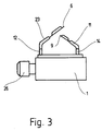
- Figur 3
- zeigt in einer verkleinerten Seitenansicht des Gehäuseteils die Stellung der abgebogenen Zuleitungen.
- Das in Figur 1 dargestellte Gehäuseteil hat eine im wesentlichen ebene Wand 2, in welche eine Metallplatte 3, insbesondere aus Aluminium, eingespritzt ist. Die Wand 2 wird von schmalen Seitenwänden 4 umrahmt, welche in einem Stück mit der Wand 2 gespritzt werden. Durch die Wand 2 führen zwei Gruppen von je drei Zuleitungen 5, 6 und 7 sowie 8, 9 und 10 hindurch. Die Zuleitungen 5, 6 und 7 haben auf einem Teil ihrer Länge einen gemeinsamen Mantel 8. Die Zuleitungen 8, 9 und 10 haben auf einem Teil ihrer Länge einen gemeinsamen Mantel 11. Der Mantel 8 besteht aus einem ersten Abschnitt 2, welcher auf der Wand 2 fußt und in einem Arbeitsgang mit dem Gehäuseteil 1 aus einem thermoplastischen Hartkunststoff gespritzt ist. An den ersten Abschnitt 12 schließt sich ein zweiter Abschnitt 13 an, welcher aus einem elastomeren Kunststoff gespritzt ist. Der zweite Abschnitt 13 wird vor dem ersten Abschnitt 12 in einem gesonderten Spritzwerkzeug gespritzt und verbindet sich beim Spritzen des ersten Mantelabschnitts 12 mit diesem fest und innig. Dementsprechend besteht auch der Mantel 11 aus einem ersten, auf der Wand 2 fußenden Abschnitt 14 aus einem thermoplastischen Hartkunststoff und aus einem daran anschließenden zweiten Abschnitt 15 aus einem elastomeren Kunststoff.
- Die Zuleitungen 5, 6 und 7 sind durch Stanzen aus einem Metallband, insbesondere aus einem mit Aluminium plattierten Kupferband, gebildet. Dementsprechend sind auch die Zuleitungen 8, 9 und 10 durch Stanzen aus einem Metallband gebildet. Deshalb bilden die drei jeweils gemeinsam ummantelten Zuleitungen 5, 6 und 7 bzw. 8, 9 und 10 ein flaches Gebilde, dessen Mantel z.B. ungefähr rechteckige Umrißlinien hat. Der flache Mantel 8 hat in seinem zweiten Abschnitt 13 auf der dem Mantel 11 zugewandten Seite eine schmale, quer über die gesamte Breite des Mantels verlaufende Rille 16 und auf der gegenüberliegenden Seite eine dazu parallele Schwächung 17, welche weniger steil abfällt als die Rille 16 und deshalb breiter als diese ist. Die Rille 16 und die Schwächung 17 bilden gemeinsam eine Taille, welche das Biegen der ummantelten Zuleitungen 5, 6 und 7 erleichtert; dabei markiert die Rille 16 die Lage der Biegestelle (Sollbiegestelle), wohingegen die Schwächung 17 auf der gegenüberliegenden Seite den Biegevorgang erleichtert. Dementsprechend hat der zweite Mantel 11 in seinem zweiten Abschnitt 15 eine dem ersten Mantel 8 zugewandte Rille 18 als Sollbiegestelle und auf der gegenüberliegenden Seite eine Schwächung 19.
- In Figur 3 sind die Zuleitungen schematisch in ihrer abgebogenen Stellung dargestellt.
- An den vier Seitenflächen 4 des Gehäuseteils 1 befinden sich doppelt wirkende Rasthaken 20, bei welchen durch einen Längsschlitz 21 zwei Schenkel gebildet sind, die gegeneinander federn können. Diese Rasthaken sind in einem Stück mit dem Gehäuseteil 1 gespritzt. Sie dienen dazu, um das Gehäuseteil mit einem Deckel 22 (Figur 2) zu verrasten, der an der Innenseite seiner vier Seitenwände 24 beim Spritzgießen durch Schieber in der Spritzgießform gebildete T-förmige Ausnehmungen 25 hat, in welche die Rasthaken 20 einführbar sind und dann einrasten. Dieser Rastverschluß kann nur durch Zerstören zumindest eines Teils der Rasthaken geöffnet werden und dient als Sicherung gegen unbefugtes Öffnen des Gehäuses, in welchem sich eine elektrische Schaltung befindet. Eine der Seitenwände 24 des Deckels hat eine Ausnehmung 25, in welche ein dem Gehäuseteil 1 angespritzter Stecker 26 eingreifen kann. Sollte der Platz neben dem Stecker zu knapp sein für zwei doppelt wirkende Rasthaken, können dort auch zwei einfach wirkende Rasthaken 27 vorgesehen sein.
- Nach dem Herstellen des Gehäuseteils 1 und dem Abbiegen der Zuleitungen 5 bis 7 und 8 bis 10 können an diesen Meßfühler angebracht werden, z.B. ein Temperaturfühler und ein Fühler zum Messen der Luftgeschwindigkeit oder des Luftdurchsatzes.
Claims (4)
- Aus Kunststoff gespritztes Gehäuseteil (1) mit starren, metallischen, eingespritzen Zuleitungen (5-10), welche eine Wand (2) des Gehäuseteils (1) durchqueren und ausgehend von der Wand (2) noch auf einem Teil ihrer Länge einen Mantel (8, 11) aus Kunststoff haben und zum Anbringen von Meßfühlern dienen, dadurch gekennzeichnet, dass der Mantel (8, 11) in einem ersten, an die Wand (2) anschließenden Abschnitt (12, 14) aus dem thermoplastischen Kunststoff besteht, aus welchem das Gehäuseteil (1) gespritzt ist,
dass der Mantel (8, 11) in einem an den ersten Abschnitt (12, 14) anschließenden zweiten Abschnitt (13, 15) aus einem elastomeren Kunststoff besteht,
dass die beiden Abschnitte (12, 13; 14, 15) einstückig miteinander verbunden sind
und dass die ummantelten Zuleitungen (5-10) im zweiten Abschnitt (13, 15) abgebogen sind. - Gehäuseteil nach Anspruch 1, dadurch gekennzeichnet, dass die Zuleitungen (5-10) Stanzteile sind.
- Gehäuseteil nach Anspruch 1 oder 2, dadurch gekennzeichnet, dass der Mantel (8, 11) im zweiten Abschnitt (13, 15) eine Taille (16, 17; 18, 19) hat, in welcher die ummantelten Zuleitungen (5-10) abgebogen sind.
- Gehäuseteil nach Anspruch 3, dadurch gekennzeichnet, dass die Taille durch eine schmale Rille (16, 18) auf der einen Seite der Zuleitung (5-10) und durch eine zur Rille (16, 18) parallele, aber verglichen mit der Rille (16, 18) breitere Schwächung (17, 19) des Mantels (8, 11) gebildet ist.
Applications Claiming Priority (4)
| Application Number | Priority Date | Filing Date | Title |
|---|---|---|---|
| DE9418706U | 1994-11-22 | ||
| DE9418706 | 1994-11-22 | ||
| DE29506697U DE29506697U1 (de) | 1994-11-22 | 1995-04-20 | Aus Kunststoff gespritztes Gehäuseteil mit starren, metallischen, eingespritzten Zuleitungen |
| DE29506697U | 1995-04-20 |
Publications (3)
| Publication Number | Publication Date |
|---|---|
| EP0714227A2 true EP0714227A2 (de) | 1996-05-29 |
| EP0714227A3 EP0714227A3 (de) | 1997-05-28 |
| EP0714227B1 EP0714227B1 (de) | 1998-10-28 |
Family
ID=25962665
Family Applications (1)
| Application Number | Title | Priority Date | Filing Date |
|---|---|---|---|
| EP95118326A Expired - Lifetime EP0714227B1 (de) | 1994-11-22 | 1995-11-22 | Aus Kunststoff gespritztes Gehäuseteil mit starren, metallischen, eingespritzten Zuleitungen |
Country Status (2)
| Country | Link |
|---|---|
| EP (1) | EP0714227B1 (de) |
| ES (1) | ES2124952T3 (de) |
Cited By (2)
| Publication number | Priority date | Publication date | Assignee | Title |
|---|---|---|---|---|
| DE29800780U1 (de) * | 1998-01-19 | 1998-04-02 | Klöckner-Moeller GmbH, 53115 Bonn | Isolierstoffgehäuse für elektrische Geräte |
| WO2021001253A1 (de) * | 2019-07-02 | 2021-01-07 | Kolektor Group D.O.O. | Elektrische oder elektronische baugruppe sowie verfahren zur herstellung eines elektrischen oder elektronischen bauteils |
Family Cites Families (2)
| Publication number | Priority date | Publication date | Assignee | Title |
|---|---|---|---|---|
| DE4017077A1 (de) * | 1990-05-26 | 1991-11-28 | Bosch Gmbh Robert | Gas- und fluessigkeitsdichte kabeldurchfuehrung |
| US5278497A (en) * | 1991-06-18 | 1994-01-11 | Mitsubishi Denki K.K. | Magnetic sensor having a magnet-sensitive plane of an MR element arranged perpendicular to both a substrate plane and a magnet |
-
1995
- 1995-11-22 EP EP95118326A patent/EP0714227B1/de not_active Expired - Lifetime
- 1995-11-22 ES ES95118326T patent/ES2124952T3/es not_active Expired - Lifetime
Non-Patent Citations (1)
| Title |
|---|
| None |
Cited By (6)
| Publication number | Priority date | Publication date | Assignee | Title |
|---|---|---|---|---|
| DE29800780U1 (de) * | 1998-01-19 | 1998-04-02 | Klöckner-Moeller GmbH, 53115 Bonn | Isolierstoffgehäuse für elektrische Geräte |
| WO2021001253A1 (de) * | 2019-07-02 | 2021-01-07 | Kolektor Group D.O.O. | Elektrische oder elektronische baugruppe sowie verfahren zur herstellung eines elektrischen oder elektronischen bauteils |
| CN114269540A (zh) * | 2019-07-02 | 2022-04-01 | 科莱克特集团公司 | 电气或电子构件以及制造电气或电子构件的方法 |
| US20220118662A1 (en) * | 2019-07-02 | 2022-04-21 | Kolektor Group D.O.O. | Electrical or electronic assembly and method for producing an electrical or electronic component |
| US11752674B2 (en) * | 2019-07-02 | 2023-09-12 | Kolektor Mobility d.o.o. | Electrical or electronic assembly and method for producing an electrical or electronic component |
| CN114269540B (zh) * | 2019-07-02 | 2024-06-11 | 科莱克特集团公司 | 电气或电子构件以及制造电气或电子构件的方法 |
Also Published As
| Publication number | Publication date |
|---|---|
| ES2124952T3 (es) | 1999-02-16 |
| EP0714227B1 (de) | 1998-10-28 |
| EP0714227A3 (de) | 1997-05-28 |
Similar Documents
| Publication | Publication Date | Title |
|---|---|---|
| EP1531272B1 (de) | Lüfter mit einem Sensor | |
| DE102007026928B4 (de) | Harzgeformte Komponente, welche mit einer Metallplatte versehen ist und Form-bzw. Gießverfahren dafür | |
| DE4215041C3 (de) | Elektronisches Steuergerät | |
| EP0258677B1 (de) | Tragplatte zum Einbau in einen Elektromotor | |
| DE10339945B4 (de) | Elektrischer Verteilerkasten und Verfahren zum Abschneiden von Drähten | |
| DE19723664A1 (de) | Steuereinheit für einen Elektromotor | |
| EP1133012B1 (de) | Steckbarer Klemmenkasten | |
| DE69737429T2 (de) | Leiterplattenverbinder | |
| DE19726496B4 (de) | Anlasser für eine Brennkraftmaschine | |
| DE3345435C2 (de) | Elektrischer Steckverbinder, insbesondere Miniatursteckverbinder | |
| DE69105428T2 (de) | Einen komplexen Aufbau aufweisender elektrischer Motor mit elektronischer Kommutation. | |
| DE29506697U1 (de) | Aus Kunststoff gespritztes Gehäuseteil mit starren, metallischen, eingespritzten Zuleitungen | |
| EP0714227B1 (de) | Aus Kunststoff gespritztes Gehäuseteil mit starren, metallischen, eingespritzten Zuleitungen | |
| EP0187902B1 (de) | Gehäuse für ein elektrisches Bauteil | |
| EP0116162B1 (de) | Einrichtung für die Steckmontage eines elektrischen Schaltungsträgers auf einem elektrischen Gerät oder dergleichen sowie Verfahren zur Herstellung der Einrichtung | |
| DE2622916C2 (de) | Elektromotor | |
| EP0410119B1 (de) | Temperaturschalter mit Bimetall-Schaltwerk | |
| DE112019003112T5 (de) | Motor | |
| DE2626328B2 (de) | Anordnung eines Schaltplattengehäuse im Motorraum | |
| WO2017125542A1 (de) | Elektronikeinheit für ein durchflussmessgerät | |
| DE102006042417A1 (de) | Transportgehäuse für eine elektronische Flachbaugruppe | |
| DE10224841B4 (de) | Vorrichtung zum elektrischen Verbinden von Kontaktstellen auf benachbarten Leiterplatten | |
| EP0419694A1 (de) | Baugruppen zum Anschluss an einen Baugruppenträger | |
| CH715074A1 (de) | Verfahren zum Herstellen einer Gehäusebaugruppe für einen Verbrauchszähler und derselbe. | |
| EP0714228A2 (de) | Zweiteiliges Gehäuse aus Kunststoff zum Aufnehmen einer elektronischen Schaltung |
Legal Events
| Date | Code | Title | Description |
|---|---|---|---|
| PUAI | Public reference made under article 153(3) epc to a published international application that has entered the european phase |
Free format text: ORIGINAL CODE: 0009012 |
|
| AK | Designated contracting states |
Kind code of ref document: A2 Designated state(s): DE ES FR GB IT SE |
|
| PUAL | Search report despatched |
Free format text: ORIGINAL CODE: 0009013 |
|
| RAP1 | Party data changed (applicant data changed or rights of an application transferred) |
Owner name: DODUCO GMBH + CO DR. EUGEN DUERRWAECHTER I.K. |
|
| AK | Designated contracting states |
Kind code of ref document: A3 Designated state(s): DE ES FR GB IT SE |
|
| 17P | Request for examination filed |
Effective date: 19970630 |
|
| GRAG | Despatch of communication of intention to grant |
Free format text: ORIGINAL CODE: EPIDOS AGRA |
|
| RAP1 | Party data changed (applicant data changed or rights of an application transferred) |
Owner name: DODUCO GMBH |
|
| GRAG | Despatch of communication of intention to grant |
Free format text: ORIGINAL CODE: EPIDOS AGRA |
|
| GRAH | Despatch of communication of intention to grant a patent |
Free format text: ORIGINAL CODE: EPIDOS IGRA |
|
| 17Q | First examination report despatched |
Effective date: 19980421 |
|
| GRAH | Despatch of communication of intention to grant a patent |
Free format text: ORIGINAL CODE: EPIDOS IGRA |
|
| GRAA | (expected) grant |
Free format text: ORIGINAL CODE: 0009210 |
|
| AK | Designated contracting states |
Kind code of ref document: B1 Designated state(s): DE ES FR GB IT SE |
|
| REF | Corresponds to: |
Ref document number: 59504062 Country of ref document: DE Date of ref document: 19981203 |
|
| ET | Fr: translation filed | ||
| ITF | It: translation for a ep patent filed | ||
| REG | Reference to a national code |
Ref country code: ES Ref legal event code: FG2A Ref document number: 2124952 Country of ref document: ES Kind code of ref document: T3 |
|
| GBT | Gb: translation of ep patent filed (gb section 77(6)(a)/1977) |
Effective date: 19990128 |
|
| RAP2 | Party data changed (patent owner data changed or rights of a patent transferred) |
Owner name: AMI DODUCO GMBH |
|
| PLBE | No opposition filed within time limit |
Free format text: ORIGINAL CODE: 0009261 |
|
| STAA | Information on the status of an ep patent application or granted ep patent |
Free format text: STATUS: NO OPPOSITION FILED WITHIN TIME LIMIT |
|
| 26N | No opposition filed | ||
| PGFP | Annual fee paid to national office [announced via postgrant information from national office to epo] |
Ref country code: GB Payment date: 20001211 Year of fee payment: 6 |
|
| PGFP | Annual fee paid to national office [announced via postgrant information from national office to epo] |
Ref country code: FR Payment date: 20001215 Year of fee payment: 6 |
|
| PGFP | Annual fee paid to national office [announced via postgrant information from national office to epo] |
Ref country code: SE Payment date: 20001222 Year of fee payment: 6 |
|
| PGFP | Annual fee paid to national office [announced via postgrant information from national office to epo] |
Ref country code: ES Payment date: 20001226 Year of fee payment: 6 |
|
| PG25 | Lapsed in a contracting state [announced via postgrant information from national office to epo] |
Ref country code: GB Free format text: LAPSE BECAUSE OF NON-PAYMENT OF DUE FEES Effective date: 20011122 |
|
| PG25 | Lapsed in a contracting state [announced via postgrant information from national office to epo] |
Ref country code: SE Free format text: LAPSE BECAUSE OF NON-PAYMENT OF DUE FEES Effective date: 20011123 Ref country code: ES Free format text: LAPSE BECAUSE OF NON-PAYMENT OF DUE FEES Effective date: 20011123 |
|
| REG | Reference to a national code |
Ref country code: GB Ref legal event code: IF02 |
|
| EUG | Se: european patent has lapsed |
Ref document number: 95118326.8 |
|
| GBPC | Gb: european patent ceased through non-payment of renewal fee |
Effective date: 20011122 |
|
| PG25 | Lapsed in a contracting state [announced via postgrant information from national office to epo] |
Ref country code: FR Free format text: LAPSE BECAUSE OF NON-PAYMENT OF DUE FEES Effective date: 20020730 |
|
| REG | Reference to a national code |
Ref country code: FR Ref legal event code: ST |
|
| REG | Reference to a national code |
Ref country code: FR Ref legal event code: ST |
|
| REG | Reference to a national code |
Ref country code: ES Ref legal event code: FD2A Effective date: 20021213 |
|
| PG25 | Lapsed in a contracting state [announced via postgrant information from national office to epo] |
Ref country code: IT Free format text: LAPSE BECAUSE OF NON-PAYMENT OF DUE FEES Effective date: 20051122 |
|
| PGFP | Annual fee paid to national office [announced via postgrant information from national office to epo] |
Ref country code: DE Payment date: 20141023 Year of fee payment: 20 |
|
| REG | Reference to a national code |
Ref country code: DE Ref legal event code: R071 Ref document number: 59504062 Country of ref document: DE |