EP0713662A1 - Furniture system - Google Patents
Furniture system Download PDFInfo
- Publication number
- EP0713662A1 EP0713662A1 EP95118383A EP95118383A EP0713662A1 EP 0713662 A1 EP0713662 A1 EP 0713662A1 EP 95118383 A EP95118383 A EP 95118383A EP 95118383 A EP95118383 A EP 95118383A EP 0713662 A1 EP0713662 A1 EP 0713662A1
- Authority
- EP
- European Patent Office
- Prior art keywords
- groove
- furniture system
- studs
- support
- stud
- Prior art date
- Legal status (The legal status is an assumption and is not a legal conclusion. Google has not performed a legal analysis and makes no representation as to the accuracy of the status listed.)
- Granted
Links
Images


Classifications
-
- A—HUMAN NECESSITIES
- A47—FURNITURE; DOMESTIC ARTICLES OR APPLIANCES; COFFEE MILLS; SPICE MILLS; SUCTION CLEANERS IN GENERAL
- A47B—TABLES; DESKS; OFFICE FURNITURE; CABINETS; DRAWERS; GENERAL DETAILS OF FURNITURE
- A47B57/00—Cabinets, racks or shelf units, characterised by features for adjusting shelves or partitions
- A47B57/06—Cabinets, racks or shelf units, characterised by features for adjusting shelves or partitions with means for adjusting the height of the shelves
- A47B57/08—Cabinets, racks or shelf units, characterised by features for adjusting shelves or partitions with means for adjusting the height of the shelves consisting of grooved or notched ledges, uprights or side walls
- A47B57/10—Cabinets, racks or shelf units, characterised by features for adjusting shelves or partitions with means for adjusting the height of the shelves consisting of grooved or notched ledges, uprights or side walls the grooved or notched parts being the side walls or uprights themselves
-
- A—HUMAN NECESSITIES
- A47—FURNITURE; DOMESTIC ARTICLES OR APPLIANCES; COFFEE MILLS; SPICE MILLS; SUCTION CLEANERS IN GENERAL
- A47B—TABLES; DESKS; OFFICE FURNITURE; CABINETS; DRAWERS; GENERAL DETAILS OF FURNITURE
- A47B96/00—Details of cabinets, racks or shelf units not covered by a single one of groups A47B43/00 - A47B95/00; General details of furniture
Definitions
- the invention relates to a furniture system in the form of a modular system of relatively freely combinable individual parts, which is basically constructed according to the principle of the known so-called gallery walls.
- gallery walls consist of essentially vertical, load-bearing elements, the so-called galleries, which can be more sheet-like structures or more column-like structures, and insert parts which are introduced essentially horizontally between two adjacent galleries.
- These insert parts can be shelves to create shelf systems or cabinet bodies to create individual cabinet areas within such a gallery wall.
- Such gallery walls can be arranged both along walls, as shelving systems or cupboard systems, or also freely standing in the room, as so-called room dividers.
- tunnel wall systems require comparatively differently designed individual parts depending on their use as a shelving system, cupboard system, room divider, since, depending on the intended use, one or more sides of the tunnel must be provided with receiving holes, in addition to the front end face, the rear end face also be veneered must and the like.
- connection of the insert parts with the studs should nevertheless be sufficiently secure and as heavy-duty as possible so that it can also be used in the commercial area, that is to say for furnishing offices or sales rooms.
- shelf supports at the desired height into the corresponding holes, on which the insert parts, in particular the shelves, can be placed, can be produced efficiently, but visually unappealing and only slightly resilient.
- grooves which extend in the least over the entire depth of the studs, can be subjected to much greater loads, although the studs do not have to be as deep as the insert parts. Rather, these can protrude both forwards and backwards over the studs, which in the case of systems to be fastened to the wall in particular means that the center of gravity of the insert parts, in particular when these are loaded, lies in front of the studs, and thus horizontally in the support groove inserted, for example, shelf is jammed due to this leverage.
- friction bodies which are arranged between the groove base and the insert parts and which consist at least on their surface of a material with good static friction. These friction bodies are arranged so that they are arranged under pressure between the bottom of the support grooves and the side surfaces of the insert parts projecting into the support grooves.
- a particularly simple, inexpensive and easy-to-use form of such a friction body is a piece of a rubber cord, the assembly being simplified particularly in the case of use as a room divider by stretching the rubber cord in the longitudinal direction during insertion of the shelves and thereby reducing the cross-section , so that there is still no pressure in the transverse direction between the bottom of the groove and the shelf to be inserted. Only after the shelf is in position does the longitudinal expansion of the rubber cord stop, and this is compressed in the transverse direction between the groove base and shelf due to its inherent elasticity. The protruding ends of the rubber cord can be cut.
- a friction body with a non-round, for example elliptical, cross section, which, with a standing cross section, does not prevent a shelf from being pushed into the groove, but causes a compression in the transverse direction after rotation by 90 °.
- the existing friction between the inserted shelf and the support grooves is usually sufficient, the difference in size of which should be about 2/10 mm, which already provides sufficient static friction with a length of the groove of about 8 - 10 cm, and above all when the insert protrudes several times the depth of the studs over it.
- the horizontal parts of the insert parts protrude, e.g. Bottom and top end of a cabinet body, laterally beyond the side surfaces of the body, in order to be able to extend into the carrying grooves.
- the cabinet body can preferably be assembled only after two spaced-apart shelves have been inserted, which then serve as the bottom and upper end of the cabinet body, which is then supplemented by side walls and doors, etc. to form the cabinet body.
- a problem with such a cabinet body can be that if the cabinet body is of sufficiently high design, individual shelves should again be present within the cabinet body, but should be decomposable as required. If the shelves forming the base and the cover part are not wider than the clear distance from one support groove to that of the opposite support groove, there is a door attached to the cabinet body even in the open state in this area, so that inserted in the support grooves, within the cabinet body placed additional shelves can not be removed without removing the entire cabinet body from the studs.
- the side walls for the cabinet body can be set in corresponding, usually arranged outside the doors, vertical grooves of the bottom and the cover part.
- a preferred solution in the choice of material is to produce the studs from so-called medium-density fiberboard (MDF), which means that grinding is not required after cutting the support grooves, and the studs can therefore be produced at particularly low cost in the desired color design.
- MDF medium-density fiberboard
- Glass shelves are used in particular as shelves.
- the visual design of the furniture system is therefore limited to the design of the studs, especially when using glass plates as shelves.
- These can be adapted very well to the visual requirements in individual cases by incorporating a pilast groove in the front surface of the symmetrically designed studs, which inserts a pilast equipped with a corresponding extension, which extends essentially over the entire length of the stud, that is, an attachment.
- the pilaster strip can have a width that is less than the distance between the two sides in the side walls the grooves made in the stud. However, it can also have a width that partially covers the groove, for example the friction bodies located in the grooves. This can be useful, for example, if the friction body is inserted parallel to the shelf when the shelves are pushed in, i.e. there is little or no relative movement between the friction body and the shelf, but sliding friction between the friction body and the groove base.
- the pilaster strip also covers the friction body towards the front, and the pilaster block is also locked against pulling out, the pilaster strip also provides a partially positive locking against a relative movement between the friction body and the groove, and thus pulling it out the shelves.
- the support grooves are preferably formed continuously from the front surface to the back surface of the studs.
- the studs are not only symmetrical to the central plane, which lies between the two side surfaces provided with grooves, but also to the transverse plane. If, on the other hand, the studs are intended for use as a wall system, at least one cable groove is provided in the back surface instead of a Lisenennut. This can be to the side of the center so as not to damage the inserted cables when screwing through the center plane, or it can be so wide that it also extends over the center region.
- the screw connection is not to be provided through a simple hole through the body of the studs, but the hole is equipped with a screw sleeve which protrudes in the cable groove and to the rear The end of the stud protrudes so that the cables inserted into the cable groove are protected by the screw sleeve against damage when screwing the stud.
- the cable groove When arranged to the side of the center, the cable groove can extend into the side surface of the stud. The cable is then visible when looking at the furniture system from an angle, but not from the front, and it is very easy to assemble by only slightly pulling the existing shelves forward to make it possible to insert a cable in the cable groove behind it . By pushing the shelves all the way back, the cables are then pushed back into the bottom of the cable groove in the area outside the support grooves.
- the support grooves are most easily produced by simply cutting or milling them out of a solid, rod-shaped block that is about 9 cm deep and 6 cm wide. Another possibility, however, is to produce the stud from a cuboid bar as a base body, on the side surfaces of which grooves are produced by fastening support plates at a height above one another and spaced apart, the spacing of which forms the support grooves. This manufacturing option is more complex, but gives more options in terms of color design and is also easier to change afterwards:
- the grooves are at regular, normal intervals one above the other along the side walls of the studs, although in some areas, such as in the area for attaching desk surfaces or standing desk writing surfaces, the distances are significantly smaller, in order to allow a more precise adjustment here to offer. This can be achieved retrospectively in the case of support plates placed on the side by exchanging these support plates for such lower heights.
- the proposed furniture system can not only be used in series, e.g. along a wall, but also around corners. It is no longer possible to insert the corner plates due to the lack of parallelism in the lateral grooves. However, this can be achieved again by not inserting the corner plate directly into the receiving support grooves, but instead holding it at its height, and only then is a so-called Y-rail placed between the support groove and corner plate by pushing in along the direction of the support groove.
- this Y-rail which is usually made of metal, has an extension on one side that fits exactly into the support groove, and on the opposite side a groove into which the corner plate in turn fits, preferably a groove according to the dimensions of the support grooves on the side walls of the studs.
- a wide variety of objects suitable for living purposes such as shelves for shelves, a cabinet body with laterally protruding floor and cover plate, a wardrobe rail with lateral, radially striving legs that are inserted into the carrying grooves, and the like can serve as insert parts themselves. Even very protruding table tops with additional sleeves arranged away from the studs can be used at any time.
- the furniture system according to the invention can be used extremely variably, despite only a small number of different individual parts.
- the subsequent replacement or redesign of pilaster strips and capitals also makes it possible to change the appearance with little effort.
- front hangers are particularly desirable for use in shop fitting. These are support bars that reach horizontally to the front or diagonally downwards, on which items of clothing can be staggered one behind the other, hanging on hangers, or other objects.
- Such front hangers are usually made of metal or sturdy plastic, and are available in different selections and from different system manufacturers ... These front hangers are usually hung with two tabs next to or one below the other in appropriately positioned openings in a retaining plate on the existing shelf system.
- these openings are present in the front panel of an essentially U-shaped U-adapter, which can then be pushed onto a stud from the front, and are supported in the carrying grooves of a stud with corresponding projections extending into the interior of the U-adapter .
- Such a U-adapter can be bent on a single U-shaped steel plate or the legs of the U-adapter on the one hand and the front plate on the other hand are separate parts cut from sheet steel, which can be positively inserted into one another by means of conventional connecting slots which are introduced up to half into the individual part.
- the slots must be so narrow that the play of this connection is small enough to avoid a gaping of the two legs into a V-shape.
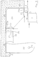
- the stud according to FIG. 1 has, in its side surfaces 25a, 25b facing away from each other and pointing to the adjacent studs, support grooves 2 into which shelves 3a to 3f are inserted.
- the stud 1 is screwed from its front surface by means of a screw 8 to the wall behind it.
- the head of the screw 8 is sunk in a slightly larger screw recess 7, which is even deeper than the Lisenennut 6, which is located in the center of the front surface of the stud 1 and is used to insert and thus fasten the pilaster strip 5 shown in the upper part of the figure.
- This attachment part can have different color and shape designs and is therefore mainly used for visual purposes Design of the visible front surface of the stud 1 and covering the screws 8.
- the pilaster strips - as shown on the left side of the pilaster strips 5 - have such a width that they only reach to the start of the carrier grooves 2, or - as shown in the right half of the figure - the carrier grooves 2 partially overlap, see above that it comes close to the free end of the shelf 3. This makes sense if a friction body is inserted between the bottom of the groove and the shelf 3.
- the rubber cord 4 shown at the top left a strongly deformed, in the initial state also round, rubber cord that must be deformed so much that it is hardly possible to insert it together with the shelf 3a.
- the insertion is then carried out by placing the rubber cord 4 on the base of the groove prior to the insertion of the shelf 3a and greatly stretching it in the longitudinal direction and thereby reducing its cross section.
- the shelf 3a is then pushed in, as can also be seen in FIG. 3 with reference to the shelf 3 shown at the bottom right and the rubber cord 4 there.
- the capital 11 consisting of three spaced capital plates 11a, 11b, 11c, can also be seen, which sits on the upper end face of the stud 1 and has a design function.
- the support grooves 2 - in contrast to the other parts of FIG. 1 - consist of distances between individual support plates 12 which are placed and fastened on the smooth, continuous side surface 25a 'of the stud 1'.
- the difficulty lies in the too precise assembly of the individual plates 12 that the support grooves 2 formed between them arise with the necessary accuracy for the function of the support system with regard to their groove width.
- the advantage is that the support plates 12 can not only be designed in color, but can also consist of a very pressure-resistant material, and the load capacity of the insert parts carried thereby is increased.
- the normal distance 14 of the support grooves 2 is essentially always uniform over the length of the studs 1. Only in certain areas - as can be seen at the top right in Fig. 1 - a contrasting, reduced paragraph 15 is selected for the support grooves if a more precise adjustment of the height of the insert parts is necessary in this area, such as for writing plates, standing desk plates and similar.
- the Y-rail 13 shown at the bottom left in FIG. 1 will be explained in more detail later with reference to FIG. 3.
- a furniture body 19 is shown as an insert, the bottom of which consists of the shelf 3f and the upper end of which consists of the shelf 3d. In between is the body 19 through side walls and e.g. a door 20 to a cabinet body 19 added.
- the cabinet body 19 is manufactured precisely with regard to the spacing of the parts 3d and 3f, it can be inserted as a whole between the studs. However, it is also possible to first push in only the shelves 3d and 3f, and then to assemble the cabinet body 19 between these shelves.
- FIGS. 1 and 2 also show the cable groove 10 or 10 'worked into the back surface 27 of the stud 1.
- this cable groove 10 is arranged off-center so that, viewed in the view of FIG. 1, it neither extends into the area of the central pilaster strip 6 and the screw recesses 7 arranged there, nor does the outer carrier groove 2 this way, cables can be pulled up in the back surface 27 of the stud 1, which cables can then be very easily moved laterally to an insert or to the capital by manual release.
- a very wide, centrally arranged cable groove 10 ' is arranged.
- a screw sleeve 9 is inserted into the bore in the stud 1, which serves to receive the screw 8, as can be seen better in FIG. 2.
- This screw sleeve 9 protrudes from the groove bottom of the cable groove 10 and ends with the rearmost edge of the stud 1.
- the cables inserted into the cable groove 10 must therefore necessarily be placed around the screw sleeve 9 and are therefore protected from damage.
- FIG. 2 the furniture system of Fig. 1 is shown in a side view, ie with a view of the side surface 25a.
- the clear, long overhang of the shelves 3b to the front over the front surface 26 of the stud 1 can also be seen.
- gallery 1 is not only shown without a pilaster strip attached, but also in use as a room divider, i.e. without being attached to a wall on the back.
- FIG. 3 shows a set-up of a furniture system in plan: While in the upper part of the picture the lugs 1 are set up along a wall 18 and firmly connected to it, the lower right lug 1 is at least partially free in the room.
- a table top 22 which is very far beyond the front surface 26 of the studs 1, is shown as an insert part, which must be supported at the free end, as a rule, by one or more feet 23.
- cloakroom rod 16 positioned in front of the front surface 26 of the cleats 1, which is inserted into the carrying grooves of the cleats 1 by means of the legs 17 which strive radially backwards from it.
- the lugs 1 adjoining the corner plate 24 and therefore also the support grooves 24 carrying the support plate 24 are at right angles to one another, so that insertion of the support plate would theoretically only be possible from the rear, but this is generally prevented by an existing wall there.
- a Y-rail 13 is inserted between the corresponding support groove 2 and the corresponding outer edge of the corner plate 24, where it is shown in the lower left corner of FIG. 1.
- This Y-rail 13 fits with its extension 35 exactly in the support groove 2 of the stud 1, and has a groove 36 opposite, in which in turn the corresponding outer edge of the corner plate 24 or an analog insert part fits exactly. As a rule, this groove becomes 36 have the same dimensions as the support grooves 2 of the studs 1.
- the Y-rail 13 can, for example, consist of aluminum profile for reasons of the weakest possible dimensioning.
- Fig. 4 a U-shaped adapter is shown, the free-ended legs 31, 31 'have such a clearance that a stud 1 fits just in between.
- the hanging openings 34 for standard front hangers 38 of different systems are accommodated.
- the lateral legs 30, 31 each have bends 32, 33 directed into the interior of the adapter 29, which are supported in a support groove 2 of a stud 1. Since this means that only one support groove 1 is to be used on each side wall 25a, 25b of the stud 1, and the thickness of the plate of the adapter is very much smaller than the width of a groove 2, the one provided with the bends, e.g. lower edge of the legs 30, 31 cranked.
- the higher, rear part has an indentation 33, which is thus supported on the upper flank of the support groove 2 in its rear region, and the lower region has an indentation 32, which is located on the lower flank of the support groove 2 in its front Support the area according to the weight load on the front hanger 38. Since only one support groove 2 is used on each side of the stud, the legs 31, 31 'can drop obliquely downwards from the upper region of the front plate 30.
- FIGS. 5a and 5b show the legs on the one hand and the front plate 30 on the other hand of a multi-part adapter construction.
- the legs 31, 31 are angular plate-shaped and have such a height that the existing bends 32, 33 on the upper edge and on the lower edge are supported on the respectively adjacent flanks of two different support grooves 2 on the same side of a stud. These can be the cheeks that are closest to each other or the most distant cheeks of two support grooves that differ in height. Furthermore, the leg 31 has a lying in front of the stud 1 in the inserted state from above Connection slot 39 which extends down to the middle and into which a front plate 30 which is transverse to it and has corresponding connection slots 39 'introduced from below can be inserted in a form-fitting manner with little play.
- a cabinet body 19 is shown with insert, which has the advantage that after opening the door without removing the cabinet body 19 from the tunnels, the existing shelves 3 within the cabinet body are height adjustable, so that the support grooves can be pulled out completely and pushed back in again.
- the single or double door 20 is mounted with a hinge 21 so far outside in the bottom of the cabinet body 19 that the inner shelves 3 do not after the door 20 has been completely opened collide with door 20.
- the floor in front of the front surface of the cleats 1 is widened as far as to the side that the pivot point of the hinge 21 can be placed far enough outside.
- a corresponding groove in the bottom and an opposite groove in the lid of the cabinet body 19 can be easily inserted into a side wall 40.
- the lug 1 and thus the support grooves facing the thickness of the bottom or lid of the cabinet body and the length of a support groove 2 can be reduced so that it corresponds to the width of the support groove 2.
- the hinges 21 are - in particular when using glass panes as doors - designed so that they are simply pushed onto the corner of a door 20 and then fixed by means of a clamping screw. This makes it possible, after inserting the initially only from the bottom, lid and side walls existing body in the tunnels to insert the individual hinges without door 20 in the corresponding receiving hole in the bottom and the lid and only then to insert the door 20 in the hinges 21 and clamp.
- the double-layered, hollow design of in particular a lid of a cabinet body is also possible, so that lighting devices etc. can be accommodated within the lid, that illuminate the inside of the cabinet body 19.
Abstract
Description
Die Erfindung betrifft ein Möbelsystem in Form eines Baukastens aus relativ frei miteinander kombinierbaren Einzelteilen, welches grundsätzlich nach dem Prinzip der bekannten sogenannten Stollen-Wände aufgebaut ist. Derartige Stollen-Wände bestehen aus im wesentlichen senkrecht verlaufenden, tragenden Elementen, den sogenannten Stollen, wobei es sich um mehr flächenartige Gebilde oder mehr säulenartige Gebilde handeln kann, sowie um im wesentlichen horizontal zwischen je zwei benachbarten Stollen eingebrachte Einsatzteile. Bei diesen Einsatzteilen kann es sich um Fachböden handeln, um Regalsysteme zu erzeugen, oder um Schrankkorpusse, um einzelne Schrankbereiche innerhalb einer solchen Stollen-Wand zu erzeugen.The invention relates to a furniture system in the form of a modular system of relatively freely combinable individual parts, which is basically constructed according to the principle of the known so-called gallery walls. Such gallery walls consist of essentially vertical, load-bearing elements, the so-called galleries, which can be more sheet-like structures or more column-like structures, and insert parts which are introduced essentially horizontally between two adjacent galleries. These insert parts can be shelves to create shelf systems or cabinet bodies to create individual cabinet areas within such a gallery wall.
Derartige Stollen-Wände können sowohl entlang von Wänden, als Regalsysteme oder Schranksysteme angeordnet werden, oder auch frei im Raum stehend, als sogenannte Raumteiler.Such gallery walls can be arranged both along walls, as shelving systems or cupboard systems, or also freely standing in the room, as so-called room dividers.
Die bekannten Stollen-Wand-Systeme erfordern jedoch je nach Verwendung als Regalsystem, Schranksystem, Raumteiler vergleichsweise unterschiedlich gestaltete Einzelteile, da in Abhängigkeit vom Verwendungszweck eine oder mehrere Seiten der Stollen mit Aufnahmebohrungen versehen werden müssen, zusätzlich zur vorderen Stirnfläche auch die hintere Stirnfläche furniert werden muß und Ähnliches.The known tunnel wall systems, however, require comparatively differently designed individual parts depending on their use as a shelving system, cupboard system, room divider, since, depending on the intended use, one or more sides of the tunnel must be provided with receiving holes, in addition to the front end face, the rear end face also be veneered must and the like.
Es ist daher die Aufgabe gemäß der Erfindung, ein Möbelsystem zu schaffen, welches einfach und kostengünstig in seiner Herstellung und Montage ist, und mit möglichst geringem Aufwand optisch verändert und die Gegebenheit angepaßt werden kann.It is therefore the object of the invention to provide a furniture system which is simple and inexpensive to manufacture and assemble, and with optically changed as little effort as possible and the circumstances can be adapted.
Dabei soll die Verbindung der Einsatzteile mit den Stollen dennoch ausreichend sicher und möglichst hoch belastbar sein, um auch Anwendung im kommerziellen Bereich, also zur Ausstattung von Büroräumen oder Verkaufsräumen, finden zu können.The connection of the insert parts with the studs should nevertheless be sufficiently secure and as heavy-duty as possible so that it can also be used in the commercial area, that is to say for furnishing offices or sales rooms.
Ferner besteht die Aufgabe, ein Verfahren zu schaffen, um die Einsatzteile möglichst schnell und dennoch sicher und kostengünstig mit den Stollen eines Möbelsystemes zu verbinden.Furthermore, there is the task of creating a method for connecting the insert parts as quickly as possible, yet safely and inexpensively, to the studs of a furniture system.
Diese Aufgabe wird durch die kennzeichnenden Merkmale des Anspruches 1 und 26 gelöst. Vorteilhafte Ausführungsformen ergeben sich aus den Unteransprüchen.This object is achieved by the characterizing features of
Gegenüber der normalen Lösung, in die Stollen eines Möbelsystemes vertikal verlaufende Lochreihen einzubringen, und an der gewünschten Höhe in die entsprechenden Löcher vorstehende Stifte, sogenannte Fachbodenträger zu stecken, auf denen die Einsatzteile, insbesondere die Fachböden, abgelegt werden können, sind zwar rationell herzustellen, aber optisch wenig ansprechend und nur gering belastbar.Compared to the normal solution of introducing rows of holes that run vertically into the studs of a furniture system and inserting protruding pins, so-called shelf supports, at the desired height into the corresponding holes, on which the insert parts, in particular the shelves, can be placed, can be produced efficiently, but visually unappealing and only slightly resilient.
Demgegenüber sind Nuten, die sich im wenetlichen über die gesamte Tiefe der Stollen erstrecken, wesentlich höher belastbar, wobei dennoch die Stollen bei weitem nicht so tief sein müssen, wie die Einsatzteile. Diese können vielmehr sowohl nach vorne, als auch nach hinten über die Stollen hervorragen, was gerade bei an der Wand zu befestigenden Systemen dazu führt, daß der Schwerpunkt der Einsatzteile, insbesondere wenn diese belastet werden, vor den Stollen liegt, und damit der horizontal in die Tragnut eingeschobene z.B. Fachboden aufgrund dieser Hebelwirkung kraftschlüssig verklemmt wird.In contrast, grooves, which extend in the least over the entire depth of the studs, can be subjected to much greater loads, although the studs do not have to be as deep as the insert parts. Rather, these can protrude both forwards and backwards over the studs, which in the case of systems to be fastened to the wall in particular means that the center of gravity of the insert parts, in particular when these are loaded, lies in front of the studs, and thus horizontally in the support groove inserted, for example, shelf is jammed due to this leverage.
Diese Klemmwirkung tritt dagegen bei mittig belasteten, als Raumteilern verwendeten, Fachböden, nicht auf. In diesem Fall könnte bei horizontaler Belastung mit derselben Kraft wie beim Einschieben unbeabsichtigt auch ein Herausschieben der Fachböden erfolgen, da die Reibung durch die Belastung der einzelnen Fachböden nur unwesentlich erhöht wird.This clamping effect, however, does not occur in the case of shelves with a central load that are used as room dividers. In this case, the shelves could be inadvertently pushed out with the same force as when being pushed in, since the friction is only insignificantly increased by the loading of the individual shelves.
Insbesondere in diesem Fall ist ein unbeabsichtigtes Herausschieben oder Herausziehen der Einsatzteile verhindert durch Reibungskörper, die zwischen dem Nutengrund und den Einsatzteilen angeordnet sind, und wenigstens an ihrer Oberfläche aus einem Material mit guter Haftreibung bestehen. Diese Reibungskörper sind so angeordnet, daß sie auf Druck zwischen dem Grund der Tragnuten und den in die Tragnuten hineinragenden Seitenflächen der Einsatzteile angeordnet sind.In this case in particular, unintentional pushing out or pulling out of the insert parts is prevented by friction bodies which are arranged between the groove base and the insert parts and which consist at least on their surface of a material with good static friction. These friction bodies are arranged so that they are arranged under pressure between the bottom of the support grooves and the side surfaces of the insert parts projecting into the support grooves.
Eine besonders einfache, kostengünstige und leicht zu handhabende Form eines solchen Reibungskörpers ist ein Stück einer Gummischnur, wobei die Montage besonders im Falle der Verwendung als Raumteiler dadurch vereinfacht wird, daß die Gummischnur während des Einschiebens der Fachböden in Längsrichtung gedehnt und dadurch im Querschnitt verringert wird, so daß noch keine Pressung in Querrichtung zwischen Nutengrund und dem einzuschiebenden Fachboden vorhanden ist. Erst nachdem der Fachboden in Position ist, wird die Längsdehnung der Gummischnur beendet, und diese verpreßt sich aufgrund ihrer Eigenelastizität in Querrichtung zwischen Nutengrund und Fachboden. Die überstehenden Enden der Gummischnur können gekappt werden.A particularly simple, inexpensive and easy-to-use form of such a friction body is a piece of a rubber cord, the assembly being simplified particularly in the case of use as a room divider by stretching the rubber cord in the longitudinal direction during insertion of the shelves and thereby reducing the cross-section , so that there is still no pressure in the transverse direction between the bottom of the groove and the shelf to be inserted. Only after the shelf is in position does the longitudinal expansion of the rubber cord stop, and this is compressed in the transverse direction between the groove base and shelf due to its inherent elasticity. The protruding ends of the rubber cord can be cut.
Denkbar ist jedoch auch, ein Reibungskörper mit unrundem, beispielsweise ellyptischem, Querschnitt, der mit stehendem Querschnitt das Einschieben eines Fachbodens in die Nut nicht verhindert, nach Drehung um 90° jedoch eine Verpressung in Querrichtung bewirkt.However, it is also conceivable to have a friction body with a non-round, for example elliptical, cross section, which, with a standing cross section, does not prevent a shelf from being pushed into the groove, but causes a compression in the transverse direction after rotation by 90 °.
Bei der Verwendung als Wandsystem, bei welchem die Fachböden oder andere Einsatzteile bündig mit der Rückenfläche der Stollen enden, aber nach vorne deutlich darüber hinaus ragen, ist meist die vorhandene Reibung zwischen dem eingeschobenen Fachboden und den Tragnuten ausreichend, deren Maßdifferenz etwa 2/10 mm betragen sollte, was bei einer Länge der Nut von etwa 8 - 10 cm bereits eine ausreichende Haftreibung erbringt, und vor allem dann, wenn das Einsatzteil um ein Mehrfaches der Tiefe der Stollen über dieses nach vorne hervorragt.When used as a wall system, in which the shelves or other insert parts end flush with the back surface of the studs, but towards the front protrude significantly beyond this, the existing friction between the inserted shelf and the support grooves is usually sufficient, the difference in size of which should be about 2/10 mm, which already provides sufficient static friction with a length of the groove of about 8 - 10 cm, and above all when the insert protrudes several times the depth of the studs over it.
Bei anderen Einsatzteilen als Fachböden ragen die waagerecht verlaufenden Teile der Einsatzteile, z.B. Boden und Oberabschluß eines Schrankkorpus, seitlich über die Seitenflächen des Korpus wiederum hinaus, um sich in die Tragnuten hinein erstrecken zu können. Dabei kann die Montage des Schrankkorpus vorzugsweise erst nach dem Einschieben zweier beabstandeter Fachböden stattfinden, die anschließend als Boden und oberer Abschluß des Schrankkorpus dienen, welcher durch Seitenwände und Türen etc. erst anschließend zum Schrankkorpus ergänzt wird.For insert parts other than shelves, the horizontal parts of the insert parts protrude, e.g. Bottom and top end of a cabinet body, laterally beyond the side surfaces of the body, in order to be able to extend into the carrying grooves. The cabinet body can preferably be assembled only after two spaced-apart shelves have been inserted, which then serve as the bottom and upper end of the cabinet body, which is then supplemented by side walls and doors, etc. to form the cabinet body.
Ein Problem bei einem derartigen Schrankkorpus kann darin bestehen, daß bei ausreichend hoher Gestaltung des Schrankkorpus innerhalb des Schrankkorpus wiederum einzelne Fachböden vorhanden sein sollen, die jedoch je nach Erfordernis zersetzbar sein sollen. Sind die den Boden und das Deckelteil bildenden Fachböden nicht breiter als der lichte Abstand von einer Tragnut zu dem der gegenüberliegenden Tragnut, so befindet sich eine am Schrankkorpus befestigte Tür selbst im geöffneten Zustand in diesem Bereich, so daß in die Tragnuten eingesetzte, innerhalb des Schrankkorpus plazierte zusätzliche Fachböden nicht herausgenommen werden können, ohne den gesamten Schrankkorpus von den Stollen zu entfernen.A problem with such a cabinet body can be that if the cabinet body is of sufficiently high design, individual shelves should again be present within the cabinet body, but should be decomposable as required. If the shelves forming the base and the cover part are not wider than the clear distance from one support groove to that of the opposite support groove, there is a door attached to the cabinet body even in the open state in this area, so that inserted in the support grooves, within the cabinet body placed additional shelves can not be removed without removing the entire cabinet body from the studs.
Dieses Problem wird durch eine Verbreiterung des Bodens und des oberen Deckels eines Schrankkorpus behoben. Die entsprechenden speziellen Fachböden sind gegenüber dem lichten Abstand zwischen den Nuten im Bereich vor den Stollen entsprechend verbreitert, so daß der Drehpunkt der Tür bzw. Türen in dem Boden bzw. Deckelteil so weit außen liegen kann, daß bei geöffneter Tür ein Einschieben und Auswechseln der innerhalb des Schrankkorpus 19 befindlichen, normalen Fachböden 3 möglich ist.This problem is solved by widening the bottom and the top lid of a cabinet body. The corresponding special shelves are widened in relation to the clear distance between the grooves in the area in front of the studs, so that the pivot point of the door or doors in the floor or cover part can be so far out that when the door is open, it is pushed in and replacement of the
Die Seitenwände für den Schrankkorpus können dabei in entsprechende, meist außerhalb der Türen angeordnete, senkrecht stehende Nuten des Bodens und des Deckelteiles eingestellt werden.The side walls for the cabinet body can be set in corresponding, usually arranged outside the doors, vertical grooves of the bottom and the cover part.
Die Montage ist bei Verwendung spezieller Einzelscharniere für den oberen und unteren Gelenkpunkt sehr einfach, die auf die Ecke der Tür einfach aufgeschoben werden, und mit einem Gelenkzapfen im Boden bzw. Deckelteil gelagert sind. Diese Scharniere können zunächst ohne die Tür in den Boden und das Deckelteil eingestellt werden, woraufhin die Tür in das Scharnier eingeschoben und dort mittels Klemmschraube fixiert wird.Installation is very easy when using special single hinges for the upper and lower hinge point, which are simply pushed onto the corner of the door and are mounted with a hinge pin in the base or cover part. These hinges can first be set in the floor and the cover part without the door, whereupon the door is pushed into the hinge and fixed there by means of a clamping screw.
Eine bevorzugte Lösung bei der Materialwahl besteht darin, die Stollen aus sogenannten mitteldichten Faserplatten (MDF) herzustellen, wodurch nach dem Schneiden der Tragnuten auf ein Schleifen verzichtet werden kann, und dadurch die Stollen besonders kostengünstig in der gewünschten Farbgestaltung erstellbar sind. Als Fachböden werden insbesondere Glasplatten verwendet.A preferred solution in the choice of material is to produce the studs from so-called medium-density fiberboard (MDF), which means that grinding is not required after cutting the support grooves, and the studs can therefore be produced at particularly low cost in the desired color design. Glass shelves are used in particular as shelves.
Die optische Gestaltung des Möbelsystems beschränkt sich - besonders bei der Verwendung von Glasplatten als Fachböden - daher nur noch auf die Gestaltung der Stollen. Diese können dadurch sehr gut den optischen Wünschen im Einzelfall angepaßt werden, indem in die Frontfläche der symmetrisch ausgebildeten Stollen eine Lisenen-Nut eingearbeitet ist, die das Einstecken einer mit einem entsprechenden Fortsatz ausgestatteten, sich im wesentlichen über die gesamte Länge der Stolle erstreckenden Lisene, also eines Vorsatzteiles, ermöglicht.The visual design of the furniture system is therefore limited to the design of the studs, especially when using glass plates as shelves. These can be adapted very well to the visual requirements in individual cases by incorporating a pilast groove in the front surface of the symmetrically designed studs, which inserts a pilast equipped with a corresponding extension, which extends essentially over the entire length of the stud, that is, an attachment.
Diese Lisene kann im Hinblick auf ihre Querschnittsform, ihre farbliche Gestaltung und ihre Oberflächengestaltung entsprechend dem Einzelfall einfach und kostengünstig angepaßt hergestellt werden. Die Lisene kann dabei eine Breite haben, die geringer ist als der Abstand zwischen den beidseits in die Seitenwände der Stolle eingebrachten Nuten. Sie kann aber auch eine solche Breite haben, die die Nut teilweise abdeckt, beispielsweise die in den Nuten liegenden Reibungskörper. Dies kann beispielsweise dann sinnvoll sein, wenn beim Einschieben der z.B. Fachböden der Reibungskörper parallel mit dem Fachboden eingeschoben wird, also keine oder kaum eine Relativbewegung zwischen dem Reibungskörper und dem Fachboden stattfindet, dagegen eine Gleitreibung zwischen dem Reibungskörper und dem Nutengrund. Hierfür ist es notwendig, daß die größere Haftreibung bzw. Gleitreibung zwischen dem Reibungskörper und der Stirnseite des Fachbodens vorhanden ist, wobei eine Gummischnur beispielsweise durch eine entsprechende Riffelung der seitlichen Stirnfläche des Fachbodens möglich ist, die quer zur Einschubrichtung verläuft.With regard to its cross-sectional shape, its color design and its surface design, this pilaster strips can be easily and inexpensively adapted to suit the individual case. The pilaster strip can have a width that is less than the distance between the two sides in the side walls the grooves made in the stud. However, it can also have a width that partially covers the groove, for example the friction bodies located in the grooves. This can be useful, for example, if the friction body is inserted parallel to the shelf when the shelves are pushed in, i.e. there is little or no relative movement between the friction body and the shelf, but sliding friction between the friction body and the groove base. For this it is necessary that the greater static friction or sliding friction is present between the friction body and the end face of the shelf, a rubber cord being possible, for example, by correspondingly corrugating the lateral end face of the shelf, which runs transversely to the direction of insertion.
Wenn in diesem Fall im fertig montierten Zustand die Lisene nach vorne auch den Reibungskörper abdeckt, und die Lisene zusätzlich gegenüber der Stolle gegen ein Herausziehen verriegelt ist, stellt die Lisene zusätzlich eine teilweise formschlüssige Sicherung gegen eine Relativbewegung zwischen Reibungskörper und Nut, und damit das Herausziehen der Fachböden, dar.If, in this case, the pilaster strip also covers the friction body towards the front, and the pilaster block is also locked against pulling out, the pilaster strip also provides a partially positive locking against a relative movement between the friction body and the groove, and thus pulling it out the shelves.
Die Tragnuten werden zum Vereinfachen der Herstellung vorzugsweise von der Frontfläche bis zur Rückenfläche der Stollen durchgängig ausgebildet. Bei Verwendung als Raumteiler sind die Stollen jedoch nicht nur zur Mittelebene, die zwischen den beiden mit Nuten ausgestatteten Seitenflächen liegt, symetrisch ausgebildet, sondern auch zur Querebene hierzu. Sind die Stollen dagegen zur Verwendung als Wandsystem vorgesehen, ist in der Rückenfläche anstatt einer Lisenennut mindestens eine Kabelnut vorgesehen. Diese kann seitlich der Mitte liegen, um die eingelegten Kabel nicht beim Verschrauben, die durch die Mittelebene hindurch erfolgt, zu beschädigen, oder sie kann so breit sein, daß sie sich auch über den mittleren Bereich hinweg erstreckt.To simplify production, the support grooves are preferably formed continuously from the front surface to the back surface of the studs. When used as a room divider, however, the studs are not only symmetrical to the central plane, which lies between the two side surfaces provided with grooves, but also to the transverse plane. If, on the other hand, the studs are intended for use as a wall system, at least one cable groove is provided in the back surface instead of a Lisenennut. This can be to the side of the center so as not to damage the inserted cables when screwing through the center plane, or it can be so wide that it also extends over the center region.
In diesem Fall ist die Verschraubung nicht durch eine einfache Bohrung durch den Körper der Stollen hindurch vorzusehen, sondern die Bohrung wird mit einer Schraubenhülse ausgestattet, die in der Kabelnut hervorragt und bis zum hintersten Ende der Stolle vorsteht, so daß die in die Kabelnut eingelegten Kabel durch die Schraubenhülse vor einer Beschädigung beim Verschrauben der Stolle geschützt sind.In this case, the screw connection is not to be provided through a simple hole through the body of the studs, but the hole is equipped with a screw sleeve which protrudes in the cable groove and to the rear The end of the stud protrudes so that the cables inserted into the cable groove are protected by the screw sleeve against damage when screwing the stud.
Bei Anordnung seitlich der Mitte kann die Kabelnut bis in die Seitenfläche der Stolle hineinreicht. Das Kabel ist dann zwar bei schräger Betrachtung des Möbelsystems sichtbar, nicht jedoch von vorne, und es ist eine sehr einfache Montage möglich, indem die vorhandenen Fachböden nur geringfügig nach vorne gezogen werden müssen, um das Einlegen eines Kabels in der Kabelnut dahinter möglich zu machen. Durch vollständiges Zurückschieben der Fachböden nach hinten werden die Kabel dann seitlich im Bereich außerhalb der Tragnuten in den Grund der Kabelnut zurückgeschoben gehalten.When arranged to the side of the center, the cable groove can extend into the side surface of the stud. The cable is then visible when looking at the furniture system from an angle, but not from the front, and it is very easy to assemble by only slightly pulling the existing shelves forward to make it possible to insert a cable in the cable groove behind it . By pushing the shelves all the way back, the cables are then pushed back into the bottom of the cable groove in the area outside the support grooves.
Die Tragnuten werden sehr paßgenau am einfachsten durch Herausschneiden oder Herausfräsen aus einem massiven, stabförmigen Block hergestellt, der etwa 9 cm tief und 6 cm breit ist. Eine andere Möglichkeit besteht jedoch darin, die Stolle aus einem quaderförmigen Stab als Grundkörper herzustellen, auf dessen Seitenflächen Nuten erzeugt werden, indem dort in der Höhe übereinander und beabstandet Tragplatten befestigt werden, deren Abstand zueinander die Tragnuten bildet. Diese Herstellungsmöglichkeit ist aufwendiger, ergibt jedoch mehr Möglichkeiten bei der farblichen Gestaltung und ist auch nachträglich leichter veränderbar:The support grooves are most easily produced by simply cutting or milling them out of a solid, rod-shaped block that is about 9 cm deep and 6 cm wide. Another possibility, however, is to produce the stud from a cuboid bar as a base body, on the side surfaces of which grooves are produced by fastening support plates at a height above one another and spaced apart, the spacing of which forms the support grooves. This manufacturing option is more complex, but gives more options in terms of color design and is also easier to change afterwards:
Denn im Normalfall befinden sich die Nuten in gleichmäßigen normalen Abständen übereinander entlang der Seitenwände der Stollen, wobei jedoch in einigen Bereichen, etwa in dem Bereich zum Anbringen von Schreibtisch-Flächen oder Stehpult-Schreibflächen, die Abstände wesentlich geringer sind, um hier eine genauere Einstellmöglichkeit zu bieten. Dies kann bei seitlich aufgesetzten Tragplatten durch einen Austausch dieser Tragplatten gegen solche geringerer Höhe nachträglich erreicht werden.Because in normal cases the grooves are at regular, normal intervals one above the other along the side walls of the studs, although in some areas, such as in the area for attaching desk surfaces or standing desk writing surfaces, the distances are significantly smaller, in order to allow a more precise adjustment here to offer. This can be achieved retrospectively in the case of support plates placed on the side by exchanging these support plates for such lower heights.
Ebenso ist es mit den aufgesetzten Tragplatten möglich, diese beispielsweise nach vorne über die Stolle hervorragen zu lassen, und damit eine wesentlich bessere Abstützung der darüber eingeschobenen Einsatzteile zu bieten.It is also possible with the attached support plates to have them protrude forward over the stud, for example, and thus to offer much better support for the insert parts inserted above them.
Darüber hinaus kann mit dem vorgeschlagenen Möbelsystem nicht nur in Reihe, z.B. entlang einer Wand, gebaut werden, sondern auch über Eck. Dabei ist zwar ein Einschieben der Eckplatten wegen der fehlenden Parallelität der seitlichen Nuten nicht mehr möglich. Dies kann jedoch wieder erreicht werden, indem die Eckplatte nicht direkt in die aufnehmenden Tragnuten eingeschoben werden, sondern auf deren Höhe gehalten werden, und erst dann eine sogenannte Y-Schiene zwischen Tragnut und Eckplatte gesetzt wird durch Einschieben entlang der Richtung der Tragnut. Um diese formschlüssige Verbindung herzustellen, weist diese meist aus Metall bestehende Y-Schiene auf der einen Seite einen Fortsatz auf, der in die Tragnut genau hineinpaßt, und auf der gegenüberliegenden Seite eine Nut, in die wiederum die Eckplatte genau hineinpaßt, vorzugsweise also eine Nut entsprechend den Abmessungen der Tragnuten an den Seitenwänden der Stollen.In addition, the proposed furniture system can not only be used in series, e.g. along a wall, but also around corners. It is no longer possible to insert the corner plates due to the lack of parallelism in the lateral grooves. However, this can be achieved again by not inserting the corner plate directly into the receiving support grooves, but instead holding it at its height, and only then is a so-called Y-rail placed between the support groove and corner plate by pushing in along the direction of the support groove. In order to produce this form-fitting connection, this Y-rail, which is usually made of metal, has an extension on one side that fits exactly into the support groove, and on the opposite side a groove into which the corner plate in turn fits, preferably a groove according to the dimensions of the support grooves on the side walls of the studs.
Als Einsatzteile selbst können die unterschiedlichsten für Wohnzwecke geeigneten Gegenstände wie Fachböden für Regale, ein Schrankkorpus mit seitlich überstehendem Boden und Deckplatte, eine Garderobenstange mit seitlichen, radial abstrebenden Schenkeln, die in die Tragnuten eingeschoben werden, und Ähnliches dienen. Auch sehr weit ausragende Tischplatten mit zusätzlich von den Stollen entfernt angeordneten, abstützenden Hülsen können jederzeit eingesetzt werden.A wide variety of objects suitable for living purposes such as shelves for shelves, a cabinet body with laterally protruding floor and cover plate, a wardrobe rail with lateral, radially striving legs that are inserted into the carrying grooves, and the like can serve as insert parts themselves. Even very protruding table tops with additional sleeves arranged away from the studs can be used at any time.
Auf diese Art und Weise ist das erfindungsgemäße Möbelsystem äußerst variabel einsetzbar, trotz nur geringer Anzahl unterschiedlicher Einzelteile. Auch ist durch das nachträgliche Austauschen oder Umgestalten von Lisenen und Kapitellen eine optische Veränderung mit geringem Aufwand möglich.In this way, the furniture system according to the invention can be used extremely variably, despite only a small number of different individual parts. The subsequent replacement or redesign of pilaster strips and capitals also makes it possible to change the appearance with little effort.
Gleiches gilt für die Verwendung von Kapitellen auf den oberen Stirnflächen der Stollen, die bei der Verwendung als Wandsystem, indem kein Verspreizen gegenüber der Raumdecken notwendig ist, verwendet werden können.The same applies to the use of capitals on the upper end faces of the tunnels, which can be used when used as a wall system, since no expansion to the ceiling is necessary.
Speziell für die Verwendung im Ladenbau ist die Verwendung handelsüblicher sogenannter Fronthänger wünschenswert. Dabei handelt es sich um waagerecht nach vorne oder schräg nach unten vorne reichende Tragstangen, an welchen Bekleidungsstücke hintereinander gestaffelt, an Bügeln hängend, ausgestellt werden können, oder auch andere Gegenstände. Derartige Fronthänger bestehen meist aus Metall oder stabilem Kunststoff, und sind in unterschiedlicher Auswahl und von verschiedenen System-Herstellern ... Diese Fronthänger werden meist mit zwei nebeneinander oder untereinander liegenden Rastnasen in entsprechend positionierte Öffnungen eines am vorhandenen Regalsystem vorhandenen Haltebleches eingehängt.The use of commercially available so-called front hangers is particularly desirable for use in shop fitting. These are support bars that reach horizontally to the front or diagonally downwards, on which items of clothing can be staggered one behind the other, hanging on hangers, or other objects. Such front hangers are usually made of metal or sturdy plastic, and are available in different selections and from different system manufacturers ... These front hangers are usually hung with two tabs next to or one below the other in appropriately positioned openings in a retaining plate on the existing shelf system.
Diese Öffnungen sind beim vorliegenden Möbelsystem im Frontblech eines im wesentlichen U-förmigen U-Adapters vorhanden, der dann von vorne auf eine Stolle aufgeschoben werden kann, und mit entsprechenden, in das Innere des U-Adapters hineinreichenden Vorsprüngen sich in den Tragnuten einer Stolle abstützt.In the present furniture system, these openings are present in the front panel of an essentially U-shaped U-adapter, which can then be pushed onto a stud from the front, and are supported in the carrying grooves of a stud with corresponding projections extending into the interior of the U-adapter .
Ein solcher U-Adapter kann an einem einzigen U-förmigen Stahlblech gebogen werden oder die Schenkel des U-Adapters einerseits sowie das Frontblech andererseits sind separate aus Stahlblech geschnittene Teile, die mittels üblicher bis zur Hälfte in das Einzelteil eingebrachter Verbindungsschlitze formschlüssig ineinandergesteckt werden können. Dabei müssen die Schlitze so schmal sein, daß das Spiel dieser Verbindung gering genug ist, um ein Auseinanderklaffen der beiden Schenke zu einer V-Form zu vermeiden.Such a U-adapter can be bent on a single U-shaped steel plate or the legs of the U-adapter on the one hand and the front plate on the other hand are separate parts cut from sheet steel, which can be positively inserted into one another by means of conventional connecting slots which are introduced up to half into the individual part. The slots must be so narrow that the play of this connection is small enough to avoid a gaping of the two legs into a V-shape.
Die Herstellung in nur einem Stück aus Stahlblech ist möglich, indem entweder die Höhe des Adapters so bemessen ist, daß sowohl von der Oberkante, als auch von der Unterkante aus über die gesamte Länge der Tragnuten Hinbiegungen in das Innere des Adapters möglich sind. Wenn dabei auf einer Seitenwand der Stolle immer nur eine Nut beansprucht werden soll, müssen diese Einbiegungen im Längenbereich der Nut versetzt auf unterschiedlichen Höhen angeordnet werden, so daß es sich im vorderen Bereich entsprechend der Belastung diese Einbiegung an der unteren Flanke der Tragnut abstützt, und im hinteren Bereich an der oberen Flanke.The manufacture in only one piece from sheet steel is possible by either dimensioning the height of the adapter so that both from the top edge and from the bottom edge over the entire length of the support grooves bends into the interior of the adapter are possible. If doing so on a side wall of the stud Always only one groove is to be stressed, these bends in the length region of the groove must be arranged offset at different heights, so that it is supported in the front area according to the load on the lower flank of the support groove, and in the rear area on the upper flank .
Eine Ausführungsform gemäß der Erfindung ist im folgenden beispielhaft anhand der Figuren näher beschrieben. Es zeigen:
- Fig. 1:
- eine teilgeschnittene Frontansicht einer Stolle,
- Fig. 2:
- eine teilgeschnittene Seitenansicht einer Stolle,
- Fig. 3:
- einen Grundriss des Möbelsystems,
- Fig. 4:
- einen einstückigen Adapter für Fronthänger,
- Fig. 5:
- die Einzelteile eines mehrteiligen Adapters und
- Fig. 6:
- einen speziellen Schrankkorpus.
- Fig. 1:
- a partially sectioned front view of a tunnel,
- Fig. 2:
- a partially sectioned side view of a tunnel,
- Fig. 3:
- a floor plan of the furniture system,
- Fig. 4:
- a one-piece adapter for front hangers,
- Fig. 5:
- the individual parts of a multi-part adapter and
- Fig. 6:
- a special cabinet body.
Die Stolle gemäß Fig. 1 weist dabei in ihren voneinander wegweisenden, zu den jeweils benachbarten Stollen hinweisenden, Seitenflächen 25a, 25b Tragnuten 2 auf, in welche Fachböden 3a bis 3f eingeschoben sind.The stud according to FIG. 1 has, in its
In der oberen Bildhälfte ist zu erkennen, daß die Stolle 1 von ihrer Frontfläche her mittels einer Schraube 8 an der dahinterliegenden Wand verschraubt ist. Der Kopf der Schraube 8 ist dabei in einer etwas größeren Schraubvertiefung 7 versenkt, die nochmals tiefer ist als die Lisenennut 6, die sich mittig in der Frontfläche der Stolle 1 befindet und zum Einschieben und damit Befestigen der im oberen Bildteil dargestellten Lisene 5 dient. Dieses Aufsatzteil kann unterschiedliche Farb- und Formgestaltungen aufweisen und dient daher hauptsächlich der optischen Gestaltung der sichtbaren Frontfläche der Stolle 1 sowie dem Abdecken der Schrauben 8.In the upper half of the picture it can be seen that the
Wie zu erkennen, kann die Lisene - wie auf der linken Seite der Lisene 5 dargestellt - eine solche Breite haben, daß sie nur bis zum Beginn der Tragnuten 2 heranreicht, oder - wie in der rechten Bildhälfte dargestellt - die Tragnuten 2 teilweise überlappt, so daß sie bis nahe an das freie Ende des Fachbodens 3 heranreicht. Dies ist dann sinnvoll, wenn zwischen Nutengrund und Fachboden 3 ein Reibungskörper eingelegt ist.As can be seen, the pilaster strips - as shown on the left side of the pilaster strips 5 - have such a width that they only reach to the start of the
Dabei kann es sich um eine Gummischnur 4' handeln, die wie in der rechten oberen Bildhälfte der Fig. 1 dargestellt, zusammen mit dem Fachboden 3b eingeschoben und dabei nur relativ gering zu einem Oval verformt wird, und auch die Reibung zwischen dem Nutengrund und dem Fachboden 3b nur mäßig erhöht. Dagegen handelt es sich um die links oben dargestellte Gummischnur 4, um eine stark deformierte, im Ausgangszustand ebenfalls wiederum runde, Gummischnur, die so stark deformiert werden muß, daß ein Einschieben zusammen mit dem Fachboden 3a kaum mehr möglich ist. Das Einbringen wird dann vollzogen, indem die Gummischnur 4 vor dem Einschieben des Fachbodens 3a auf den Nutengrund gelegt und in Längsrichtung stark gedehnt und dadurch im Querschnitt verringert wird. In diesem gespannten Zustand der Gummischnur 4 wird dann der Fachboden 3a eingeschoben, wie auch in Fig. 3 anhand des rechts unten dargestellten Fachbodens 3 und der dortigen Gummischnur 4 ersichtlich.This can be a rubber cord 4 'which, as shown in the upper right half of FIG. 1, is pushed in together with the
In Fig. 1 ist ferner das Kapitell 11, bestehend aus drei beabstandeten Kapitell-Platten 11a, 11b, 11c, ersichtlich, welches auf der oberen Stirnfläche der Stolle 1 sitzt und gestalterische Funktion hat.In Fig. 1, the
Diese Kapitell-Platten können - wie in Fig. 2 dargestellt - beispielsweise in zunehmendem Maße nach vorne über die Stolle 1 hervorragen.These capitals can - as shown in Fig. 2 - protrude for example to an increasing extent over the
In der linken unteren Bildhälfte der Fig. 1 bestehen die Tragnuten 2 - im Gegensatz zu den übrigen Teilen der Fig. 1 - aus Abständen, die zwischen einzelnen, auf die glatte, durchgehende Seitenfläche 25a' der Stolle 1' aufgesetzten und befestigten Tragplatten 12.In the lower left half of FIG. 1, the support grooves 2 - in contrast to the other parts of FIG. 1 - consist of distances between
Dabei besteht die Schwierigkeit in der zu exakten Montage der einzelnen Platten 12, daß die dazwischen entstehenden Tragnuten 2 mit dem für die Funktion des Tragsystems notwendigen Genauigkeit hinsichtlich ihrer Nuten-Breite entstehen. Der Vorteil besteht jedoch darin, daß die Tragplatten 12 nicht nur farblich gestaltet sein können, sondern auch aus einem sehr druckfesten Material bestehen können, und dadurch die Belastbarkeit der hierdurch getragenen Einsatzteile erhöht wird.The difficulty lies in the too precise assembly of the
Wie in Fig. 1 ferner zu erkennen, ist der Normalabstand 14 der Tragnuten 2 über die Länge der Stollen 1 im wesentlichen immer gleichmäßig. Nur in bestimmten Bereichen wird - wie rechts oben in Fig. 1 ersichtlich - ein demgegenüber nochmals unterteilter, verringerter Absatnd 15 für die Tragnuten gewählt, wenn in diesem Bereich eine genauere Einstellung der Höhe der Einsatzteile notwendig ist, wie etwa für Schreibplatten, Stehpult-Platten und Ähnliches.As can also be seen in FIG. 1, the
Die links unten in Fig. 1 dargestellte Y-Schiene 13 wird später anhand der Fig. 3 näher erläutert.The Y-
Im rechten unteren Bildteil der Fig. 1 ist ein Möbelkorpus 19 als Einsatzteil dargestellt, dessen Boden aus dem Fachboden 3f und dessen Oberabschluß aus dem Fachboden 3d besteht. Dazwischen ist der Korpus 19 durch Seitenwände und z.B. eine Tür 20 zu einem Schrankkorpus 19 ergänzt.In the lower right part of FIG. 1, a
Bei exakter Fertigung des Schrankkorpus 19 hinsichtlich der Abstände der Teile 3d und 3f kann dieser im Ganzen zwischen die Stollen eingeschoben werden. Möglich ist jedoch auch das separate Einschieben zunächst nur der Fachböden 3d und 3f, und des anschließenden Aufbaus des Schrankkorpus 19 zwischen diesen Fachböden.If the
In den Figuren 1 und 2 ist ferner die in der Rückenfläche 27 der Stolle 1 eingearbeitete Kabelnut 10 bzw. 10' zu erkennen. In der oberen Bildhälfte der Fig. 1 ist diese Kabelnut 10 außermittig versetzt so eingeordnet, daß sie in der Ansicht der Fig. 1 betrachtet weder in den Bereich der mittigen Lisene 6 und der dort angeordneten Schraubvertiefungen 7 hineinreicht, noch die außenliegenden Tragnuten 2. Auf diese Art und Weise können in der Rückenfläche 27 der Stolle 1 Kabel hochgezogen werden, die dann durch manuelles Ausklinken sehr leicht seitlich zu einem Einsatzteil oder auch zu dem Kapitell hin verlegt werden können.FIGS. 1 and 2 also show the
Dagegen ist in der unteren Bildhälfte der Fig. 1 eine mittig angeordnete, sehr breite Kabelnut 10' angeordnet. Um die dort eingelegten Kabel beim Verschrauben der Stolle 1 vor Beschädigungen durch die Schraube 8 zu schützen, ist in die Bohrung in der Stolle 1, die der Aufnahme der Schraube 8 dient, eine Schraubenhülse 9 eingesetzt, wie besser in Fig. 2 zu erkennen. Diese Schraubenhülse 9 ragt aus dem Nutengrund der Kabelnut 10 hervor und endet mit der hintersten Kante der Stolle 1. Die in die Kabelnut 10 eingelegten Kabel müssen daher zwangsläufig um die Schraubenhülse 9 herumgelegt werden und sind dadurch vor Beschädigungen geschützt.In contrast, in the lower half of FIG. 1, a very wide, centrally arranged cable groove 10 'is arranged. In order to protect the cables inserted there when screwing the
In Fig. 2 ist das Möbelsystem der Fig. 1 in der Seitenansicht, also mit Blick auf die Seitenfläche 25a, dargestellt. Dabei ist in der oberen Bildhälfte neben der Befestigung durch die Schraube 8 in der Wand 18 auch das deutliche, weite Überstehen der Fachböden 3b nach vorne über die Frontfläche 26 der Stolle 1 zu erkennen.In Fig. 2, the furniture system of Fig. 1 is shown in a side view, ie with a view of the
In der unteren Bildhälfte ist die Stolle 1 dagegen nicht nur ohne aufgesetzte Lisene, sondern auch im Einsatz als Raumteiler dargestellt, also ohne rückseitige Befestigung an einer Wand. Dabei ragt der Korpus 19, der als Einsatzteil Verwendung findet, sowohl nach vorne als auch nach hinten über die Stolle 1 hinaus.In the lower half of the picture,
In Fig. 3 ist ein aufgebautes Möbelsystem im Grundriß dargestellt:
Während im oberen Bildteil die Stollen 1 entlang einer Wand 18 aufgestellt und mit dieser fest verbunden sind, steht die rechte untere Stolle 1 bereits wenigstens teilweise frei im Raum.3 shows a set-up of a furniture system in plan:
While in the upper part of the picture the
In der linken oberen Bildhälfte der Fig. 3 sind als Einsatzmöglichkeiten eine sehr weit über die Frontfläche 26 der Stollen 1 hervorragende Tischplatte 22 als Einsatzteil dargestellt, die am freien Ende in der Regel durch einen oder mehrere Füße 23 abgestützt werden muß.In the upper left half of FIG. 3, a
Eine andere Möglichkeit ist die vor der Frontfläche 26 der Stollen 1 positionierte Garderobenstange 16, die mittels der radial von ihr nach hinten abstrebenden Schenkel 17 in die Tragnuten der Stollen 1 eingeschoben wird.Another possibility is the
Im rechten oberen Bildteil der Fig. 3 ist die Montage einer Eckplatte 24 dargestellt.The assembly of a
Dabei liegen die an der Eckplatte 24 angrenzenden Stollen 1 und damit auch die die Tragplatte 24 tragenden Tragnuten im rechten Winkel zueinander, so daß ein Einschieben der Tragplatte theoretisch nur von hinten möglich wäre, was jedoch in der Regel durch eine dort vorhandene Wand verhindert wird.The
Ein Anbringen der Eckplatten ist dennoch möglich, indem diese so dimensioniert sind, daß sie im montierten Zustand nicht in die Tragnuten der positionierten, die Eckplatte 24 abstützenden Stollen 1 hineinragen, sondern in Abstand vor diesen enden. In dieser Soll-Lage wird zwischen die entsprechende Tragnut 2 und die entsprechende Außenkante der Eckplatte 24 eine Y-Schiene 13 eingeschoben, wo sie in der linken unteren Ecke der Fig. 1 dargestellt ist. Diese Y-Schiene 13 paßt mit ihrem Fortsatz 35 genau in die Tragnut 2 des Stollens 1, und hat gegenüberliegend eine Nut 36, in welche wiederum die entsprechende Außenkante der Eckplatte 24 oder eines analogen Einsatzteiles genau hineinpaßt. In der Regel wird diese Nut 36 die gleichen Abmessungen wie die Tragnuten 2 der Stollen 1 haben. Die Y-Schiene 13 kann aus Gründen der möglichst schwachen Dimensionierung beispielsweise aus Aluminium-Profil bestehen.It is nevertheless possible to attach the corner plates by dimensioning them so that they do not protrude into the support grooves of the positioned
In Fig. 4 ist ein U-förmiger Adapter dargestellt, dessen frei endende Schenkel 31, 31' einen solchen lichten Abstand haben, daß eine Stolle 1 gerade dazwischen paßt. In dem Frontblech 30 des Adapters sind die Einhängeöffnungen 34 für handelsübliche Fronthänger 38 verschiedener Systeme untergebracht.In Fig. 4 a U-shaped adapter is shown, the free-ended
Die seitlichen Schenkel 30, 31 weisen jeweils in das Innere des Adapters 29 hineingerichtete Einbiegungen 32, 33 auf, die sich in einer Tragnut 2 einer Stolle 1 abstützen. Da hierdurch auf jeder Seitenwand 25a, 25b der Stolle 1 nur eine solche Tragnut 1 benutzt werden soll, und die Dicke des Bleches des Adapters sehr viel geringer ist als die Breite einer Nut 2, ist die mit den Einbiegungen versehene, z.B. untere Kante der Schenke 30, 31 gekröpft. Der höher liegende, hintere Teil weist dabei eine Einbiegung 33 auf, die sich somit an der oberen Flanke der Tragnut 2 in deren hinteren Bereich abstützt, und der tiefer liegende Bereich eine Einbiegung 32, die sich an der unteren Flanke der Tragnut 2 in deren vorderen Bereich entsprechend der Gewichtsbelastung am Fronthänger 38 abstützt. Da nur eine Tragnut 2 auf jeder Seite der Stolle benutzt wird, können die Schenke 31, 31' vom oberen Bereich des Frontblechs 30 schräg nach hinten unten abfallen.The
In den Figuren 5a und 5b sind die Schenkel einerseits sowie das Frontblech 30 andererseits einer mehrteiligen Adapter-Konstruktion dargestellt.FIGS. 5a and 5b show the legs on the one hand and the
Dabei sind die Schenkel 31, 31' eckig plattenförmig und haben eine solche Höhe, die an der Oberkante und an der Unterkante vorhandenen Einbiegungen 32, 33 sich an den jeweils benachbarten Flanken zweier unterschiedlicher Tragnuten 2 derselben Seite einer Stolle abstützen. Dies können die jeweils einander nächstliegenden oder die jeweils einander am weitesten entfernt liegenden Wangen zweier in der Höhe unterschiedlicher Tragnuten sein. Ferner weist der Schenkel 31 einen im eingeschobenen Zustand vor der Stolle 1 liegenden von oben her bis zur Mitte herabreichenden Verbindungsschlitz 39 auf, in den ein hierzu querstehendes Frontblech 30, welches entsprechend von unten her eingebrachte Verbindungsschlitze 39' aufweist, mit geringem Spiel formschlüssig einsetzbar ist.The
In Fig. 6a und 6b ist ein Schrankkorpus 19 mit Einsatzteil dargestellt, der den Vorteil hat, daß nach dem Öffnen der Tür ohne Herausnehmen des Schrankkorpus 19 aus den Stollen die innerhalb des Schrankkorpus vorhandenen Fachböden 3 in der Höhe versetzbar sind, also daß die Tragnuten vollständig herausgezogen und wieder eingeschoben werden können. Zu diesem Zweck wird - wie am besten in der Aufsicht in der Fig. 6a zu erkennen - die einzelne oder doppelte Tür 20 mit einem Scharnier 21 soweit außen im Boden des Schrankkorpus 19 gelagert, daß nach vollständigem Öffnen der Tür 20 die inneren Fachböden 3 nicht mit der Tür 20 kollidieren.In Fig. 6a and 6b, a
Zu diesem Zweck ist der Boden vor der Frontfläche der Stollen 1 soweit zur Seite hin verbreitert, daß der Drehpunkt des Scharnieres 21 weit genug außen plaziert werden kann. Vorzugsweise kann dabei noch eine entsprechende Nut des Bodens und eine entgegengesetzte Nut des Deckels des Schrankkorpus 19 eine Seitenwand 40 einfach eingesetzt werden.For this purpose, the floor in front of the front surface of the
Um die dabei notwendige Dicke und Boden und Deckelteil z.B. für das Einbringen der Scharniere 21 zur Verfügung zu stellen, kann dieser - wie in Fig. 6b zu erkennen - deutlich dicker sein als es die Höhe einer Tragnut 2 ausmacht. Durch entsprechende Ausfräsungen im hinteren, der Stolle 1 und damit den Tragnuten zugewandten Bereich kann die Dicke des Bodens bzw. Deckels des Schrankkorpus sowie die Länge einer Tragnut 2 soweit verringert werden, daß sie der Breite des Tragnut 2 entspricht.In order to achieve the necessary thickness and base and cover part e.g. To provide for the insertion of the
Die Scharniere 21 sind dabei - insbesondere bei Verwendung von Glasscheiben als Türen - so gestaltet, daß sie einfach auf die Ecke einer Tür 20 aufgeschoben und dann mittels einer Klemmschraube fixiert werden. Dadurch ist es möglich, nach dem Einschieben des vorerst nur aus Boden, Deckel und Seitenwänden bestehenden Korpus in die Stollen die einzelnen Scharniere ohne Tür 20 in die entsprechende Aufnahmebohrung des Bodens und des Deckels einzusetzen und erst dann die Tür 20 wiederum in die Scharniere 21 einzuschieben und festzuklemmen.The hinges 21 are - in particular when using glass panes as doors - designed so that they are simply pushed onto the corner of a
Durch die Möglichkeit, den Boden und insbesondere auch den Deckel eines solchen Schrankkorpus deutlich dicker auszubilden, als die Höhe einer Tragnut 2 ist auch die doppellagige, hohle Ausbildung insbesondere eines Deckels eines Schrankkorpus möglich, so daß innerhalb des Deckels Beleuchtungseinrichtungen etc. untergebracht werden können, die das Innere des Schrankkorpus 19 beleuchten.Due to the possibility of making the floor and in particular the lid of such a cabinet body significantly thicker than the height of a
- 1, 1'1, 1 '
- StolleStud
- 2a, 2b, 2c2a, 2b, 2c
- TragnutenTragnuten
- 33rd
- FachbodenFold bottom
- 4, 4'4, 4 '
- GummischnurRubber cord
- 55
- LiseneLisene
- 66
- Lisenen-NutPilaster groove
- 6'6 '
- FortsatzContinuation
- 77
- SchraubvertiefungScrew recess
- 88th
- Schraubescrew
- 99
- SchraubenhülseScrew sleeve
- 10, 10'10, 10 '
- KabelnutCable groove
- 11a, 11b, 11c11a, 11b, 11c
- Kapitellcapital
- 1212th
- TragplatteSupport plate
- 1313
- Y-SchieneY-rail
- 1414
- Normal-AbstandNormal distance
- 1515
- verringerter Abstandreduced distance
- 1616
- GarderobenstangeWardrobe rail
- 17, 17'17, 17 '
- SchenkeDonate
- 1818th
- Wandwall
- 1919th
- SchrankkorpusCabinet body
- 2020th
- Türdoor
- 2121
- Scharnierhinge
- 2222
- TischplatteTable top
- 2323
- Fußfoot
- 2424th
- EckplatteCorner plate
- 25a, 25b25a, 25b
- SeitenflächenSide faces
- 2626
- FrontflächeFront surface
- 2727
- RückenflächeBack surface
- 2929
- U-AdapterU adapter
- 3030th
- FrontblechFront panel
- 31, 31'31, 31 '
- SchenkeDonate
- 3232
- untere vordere Einbiegunglower front bend
- 3333
- obere hintere Einbiegungupper rear bend
- 3434
- EinhängeöffnungenHanging openings
- 3535
- FortsatzContinuation
- 3636
- NutGroove
- 3838
- FronthängerFront trailer
- 39, 39'39, 39 '
- VerbindungsschlitzConnecting slot
- 4040
- Seitenwändeside walls
Claims (15)
dadurch gekennzeichnet, daß
characterized in that
dadurch gekennzeichnet, daß
die Haftreibung bewirkt wird, indem die Breite der Tragnut (2) nur geringfügig größer ist als die Dicke des Endes des in der Tragnut (2) liegenden Einsatzteiles.Furniture system according to claim 1,
characterized in that
the static friction is brought about by the width of the support groove (2) being only slightly larger than the thickness of the end of the insert part lying in the support groove (2).
dadurch gekennzeichnet, daß
die Haftreibung erzeugt wird, indem zwischen dem Nutengrund der Tragnut (2) und dem stirnseitigen Ende des in der Tragnut (2) liegenden Einsatzteiles ein eigenelastischer Reibungskörper, insbesondere eine Gummischnur (4, 4'), mit guthaftender Oberfläche, der unter horizontalem Druck zwischen dem Nutengrund und dem stirnseitigen Ende des Einsatzteiles steht, angeordnet ist.Furniture system according to claim 1,
characterized in that
the static friction is generated by a between the groove bottom of the support groove (2) and the front end of the insert part lying in the support groove (2) intrinsically elastic friction body, in particular a rubber cord (4, 4 '), with a well-adhering surface, which is under horizontal pressure between the groove base and the front end of the insert, is arranged.
dadurch gekennzeichnet, daß
in der Rückenfläche (27) der Stollen (1) im wesentlichen über deren gesamte Länge wenigstens eine Kabelnut eingearbeitet ist, die entweder schmal und ohne Berührung zur vertikalen Mittenebene der Stolle oder breit unter Überdeckung der Mittelebene der Stollen angeordnet ist oder ohne Berührung zur vertikalen Mittenebene der Stolle ist, aber nach außen bis zur Seitenfläche (25a, 25b) der Stolle (1) reicht.Furniture system according to one of the preceding claims,
characterized in that
In the back surface (27) of the studs (1), essentially over their entire length, at least one cable groove is incorporated, which is either narrow and arranged without touching the vertical center plane of the stud or broadly covering the center plane of the studs or without touching the vertical center plane the stud is, but extends outwards to the side surface (25a, 25b) of the stud (1).
dadurch gekennzeichnet, daß
die Tragnuten (2) der Stollen (1) durch auf die Stolle (1') aufgesetzte und mit dieser fest verbundene Tragplatten (12) gebildet werden und ggf. die Tragplatte (12) wenigstens im Bereich ihrer oberen, horizontalen Stirnfläche über die Frontfläche (26) der Stolle (1') hervorragt.Furniture system according to one of the preceding claims,
characterized in that
the support grooves (2) of the studs (1) are formed by support plates (12) placed on the stud (1 ') and firmly connected to it and, if necessary, the support plate (12) at least in the area of its upper, horizontal end face via the front face ( 26) the stud (1 ') protrudes.
dadurch gekennzeichnet, daß
characterized in that
dadurch gekennzeichnet, daß
die als Boden oder obere Abdeckung des Schrankkörpers (19) fungierenden Fachböden (3) mehrlagig und innen hohl ausgebildet sind, und dort Beleuchtungseinrichtungen, die das Innere des Schrankkorpus (19) beleuchten, angeordnet sind, welche über in den Kabelnuten (10, 10') verlegte elektrische Kabel mit dem Stromnetz des Gebäudes verbindbar sind.Furniture system according to claim 6,
characterized in that
the shelves (3), which act as the floor or top cover of the cabinet body (19), are multilayered and hollow on the inside, and there are lighting devices which illuminate the interior of the cabinet body (19), which are arranged in the cable grooves (10, 10 ') ) installed electrical cables can be connected to the power grid of the building.
dadurch gekennzeichnet, daß
das Möbelsystem eine Garderobenstange (16) mit hiervon radial nach hinten, gegen die Stollen strebenden Schenkel (17, 17') zur Aufnahme in den Tragnuten (2) umfaßt und/oder das Möbelsystem eine Schreibplatte in Stehpult-Höhe als Einsatzteil umfaßt.Furniture system according to one of the preceding claims,
characterized in that
the furniture system comprises a cloakroom bar (16) with radially rearward legs (17, 17 ') striving against the studs for receiving in the carrying grooves (2) and / or the furniture system comprises a writing surface at standing desk height as an insert.
dadurch gekennzeichnet, daß
das Möbelsystem von der Vorderkante zur Hinterkante schrägstehende Fachböden mit einer unteren Anschlagleiste als Einsatzteile zum Unterbringen von Schuhen umfaßt.Furniture system according to one of the preceding claims,
characterized in that
the furniture system from the front edge to the rear edge includes sloping shelves with a lower stop bar as insert parts for storing shoes.
dadurch gekennzeichnet, daß
characterized in that
dadurch gekennzeichnet, daß
die Einsatzteile sowohl über die Frontfläche (26) als auch über die Rückfläche (27) der Stollen (1) hinausragen und die Stollen (1) mit ihren oberen und unteren Stirnflächen fest mit dem Gebäude verbunden sind und die Stollen (1) im Querschnitt vollständig symmetrisch ausgebildet sind.Furniture system according to one of the preceding claims,
characterized in that
the insert parts protrude both beyond the front surface (26) and beyond the rear surface (27) of the studs (1) and the studs (1) are firmly connected to the building with their upper and lower end faces and the studs (1) are completely cross-sectional are symmetrical.
dadurch gekennzeichnet, daß
die Gummischnur (4) im Querschnitt so dick ist, daß ein Einschieben der Einsatzteile erst bei einem durch Längsdehnung der Gummischnur (4) verringerten Durchmesser der Gummischnur (4) möglich ist und ggf. die Gummischnur (4) mit ihrem hinteren Ende im Bereich der Rückenfläche (27) mit dem Stollen fest verbunden ist.Furniture system according to one of the preceding claims,
characterized in that
the rubber cord (4) is so thick in cross-section that insertion of the insert parts is only possible when the diameter of the rubber cord (4) is reduced due to the longitudinal expansion of the rubber cord (4) and, if necessary, the rubber cord (4) with its rear end in the area of Back surface (27) is firmly connected to the stud.
dadurch gekennzeichnet, daß
das Möbelsystem einen im wesentlichen U-förmigen U-Adapter (29) umfaßt, der auf eine Stolle mit seiner offenen Seite von vorne her aufschiebbar ist, und der in den Freiraum des U-Adapters (29) nach innen gerichtete Einbiegungen (32, 33) umfaßt, und in seinem Frontblech (30) Einhängeöffnungen (34) für handelsübliche Fronthänger (38) aufweist, wobei die frei endenden Schenkel (31) des U-Adapters (29) eine solche Länge aufweisen, daß das Frontblech (30) im vollständig in die Stolle (1) eingeschobenen Zustand ausreichend weit vor der Stolle (1) bzw. der Lisene (5) zu liegen kommt.Furniture system according to one of the preceding claims,
characterized in that
the furniture system comprises an essentially U-shaped U-adapter (29), which can be pushed onto a stud with its open side from the front, and which has inwardly directed bends (32, 33.) in the free space of the U-adapter (29) ) comprises, and in its front plate (30) hanging openings (34) for commercially available front hangers (38), the free-ended legs (31) of the U-adapter (29) have such a length that the front plate (30) in the complete inserted into the stud (1) sufficiently far before the stud (1) or the pilaster (5) comes to rest.
dadurch gekennzeichnet, daß
characterized in that
dadurch gekennzeichnet, daß
characterized in that
Applications Claiming Priority (2)
| Application Number | Priority Date | Filing Date | Title |
|---|---|---|---|
| DE4441740A DE4441740C2 (en) | 1994-11-23 | 1994-11-23 | Furniture system |
| DE4441740 | 1994-11-23 |
Publications (2)
| Publication Number | Publication Date |
|---|---|
| EP0713662A1 true EP0713662A1 (en) | 1996-05-29 |
| EP0713662B1 EP0713662B1 (en) | 2000-05-31 |
Family
ID=6533981
Family Applications (1)
| Application Number | Title | Priority Date | Filing Date |
|---|---|---|---|
| EP95118383A Expired - Lifetime EP0713662B1 (en) | 1994-11-23 | 1995-11-22 | Furniture system |
Country Status (3)
| Country | Link |
|---|---|
| EP (1) | EP0713662B1 (en) |
| AT (1) | ATE193426T1 (en) |
| DE (2) | DE4441740C2 (en) |
Cited By (1)
| Publication number | Priority date | Publication date | Assignee | Title |
|---|---|---|---|---|
| DE19905511B4 (en) * | 1999-02-10 | 2005-07-28 | Eduard Treffer | Method for securing a drawer shelf |
Citations (7)
| Publication number | Priority date | Publication date | Assignee | Title |
|---|---|---|---|---|
| DE1033501B (en) * | 1955-02-12 | 1958-07-03 | Bingo S A R L La Chaux Fonds | Carrying device for showcases u. like |
| DE2034731A1 (en) * | 1970-07-13 | 1972-01-20 | Chart Establishment, Vaduz | Wall shelf |
| DE2152187A1 (en) * | 1971-10-20 | 1973-05-03 | Tielsa Moebel Werke Gmbh | PILLAR FOR WALL CLADDING MADE OF WOOD-BASED MATERIAL |
| DE2653749A1 (en) * | 1976-11-26 | 1978-06-01 | Rosenkranz & Cie Ed | Unit furniture such as shelving or wall cupboards - has vertical uprights with support members for horizontal sections attached to longitudinal edges |
| EP0084870A2 (en) * | 1982-01-26 | 1983-08-03 | Hermann Uppenkamp GmbH & Co. KG | Interlinking sectional furniture |
| US4418967A (en) * | 1981-07-31 | 1983-12-06 | Winkelman Jr Henry T | Waffle furniture system |
| EP0482292A1 (en) * | 1990-10-26 | 1992-04-29 | Helge B. Cohausz | Rack |
Family Cites Families (2)
| Publication number | Priority date | Publication date | Assignee | Title |
|---|---|---|---|---|
| DE8905400U1 (en) * | 1989-04-28 | 1989-08-17 | Goecke, Klaus W., 4930 Detmold, De | |
| DE4200338C1 (en) * | 1992-01-09 | 1992-10-01 | Simon 4807 Borgholzhausen De Desanta |
-
1994
- 1994-11-23 DE DE4441740A patent/DE4441740C2/en not_active Expired - Fee Related
-
1995
- 1995-11-22 EP EP95118383A patent/EP0713662B1/en not_active Expired - Lifetime
- 1995-11-22 DE DE59508416T patent/DE59508416D1/en not_active Expired - Fee Related
- 1995-11-22 AT AT95118383T patent/ATE193426T1/en not_active IP Right Cessation
Patent Citations (7)
| Publication number | Priority date | Publication date | Assignee | Title |
|---|---|---|---|---|
| DE1033501B (en) * | 1955-02-12 | 1958-07-03 | Bingo S A R L La Chaux Fonds | Carrying device for showcases u. like |
| DE2034731A1 (en) * | 1970-07-13 | 1972-01-20 | Chart Establishment, Vaduz | Wall shelf |
| DE2152187A1 (en) * | 1971-10-20 | 1973-05-03 | Tielsa Moebel Werke Gmbh | PILLAR FOR WALL CLADDING MADE OF WOOD-BASED MATERIAL |
| DE2653749A1 (en) * | 1976-11-26 | 1978-06-01 | Rosenkranz & Cie Ed | Unit furniture such as shelving or wall cupboards - has vertical uprights with support members for horizontal sections attached to longitudinal edges |
| US4418967A (en) * | 1981-07-31 | 1983-12-06 | Winkelman Jr Henry T | Waffle furniture system |
| EP0084870A2 (en) * | 1982-01-26 | 1983-08-03 | Hermann Uppenkamp GmbH & Co. KG | Interlinking sectional furniture |
| EP0482292A1 (en) * | 1990-10-26 | 1992-04-29 | Helge B. Cohausz | Rack |
Cited By (1)
| Publication number | Priority date | Publication date | Assignee | Title |
|---|---|---|---|---|
| DE19905511B4 (en) * | 1999-02-10 | 2005-07-28 | Eduard Treffer | Method for securing a drawer shelf |
Also Published As
| Publication number | Publication date |
|---|---|
| DE59508416D1 (en) | 2000-07-06 |
| ATE193426T1 (en) | 2000-06-15 |
| EP0713662B1 (en) | 2000-05-31 |
| DE4441740C2 (en) | 1997-01-16 |
| DE4441740A1 (en) | 1996-05-30 |
Similar Documents
| Publication | Publication Date | Title |
|---|---|---|
| DE3438365C2 (en) | Profile rod for clamping plates, in particular glass plates for showcases, sales counters, trade fair furniture or the like. | |
| DE3200310C2 (en) | Frame made from several profile bars | |
| EP1846711B1 (en) | Refrigerating device with pull-out carrier for refrigerated goods | |
| EP2051605B1 (en) | Apparatus for displaying goods, comprising a profile and mounts which can be suspended therein | |
| DE2933303A1 (en) | FASTENING DEVICE FOR WALL CABINETS, MIRRORS, SHELVES AND THE LIKE | |
| DE1929626A1 (en) | Suspension and carrying system | |
| DE2211733B2 (en) | Kit for furniture | |
| EP0551575B1 (en) | Side wall of a drawer | |
| EP4039131B1 (en) | Shelving system | |
| EP0178598B1 (en) | Construction set for individually putting together furniture units such as show cases, selling counters, exhibition furniture or the like | |
| EP2348920B1 (en) | Construction kit | |
| DE102012109879A1 (en) | Guide device for sliding doors | |
| DE10306002A1 (en) | Carrier arrangement used in presentation of goods along a wall, has plug-in items formed with projections that form protective structure with level portion to prevent plug-in items from falling from receiving device | |
| DE1778336C3 (en) | Furniture system for assembling box furniture | |
| EP2904942A2 (en) | Shelf and/or display cabinet | |
| EP0713662B1 (en) | Furniture system | |
| DE10224588B4 (en) | Cabinet system with at least one slide-in element | |
| DE10242519B4 (en) | Drawer or the like | |
| DE3129573C2 (en) | Construction kit for furniture, in particular add-on furniture | |
| EP3685705B1 (en) | Operating device with two profiles and a wall | |
| EP2124677B1 (en) | Shelf system | |
| DE10235918B4 (en) | Assembly system for furniture and method for assembling furniture | |
| DE19833506C1 (en) | Shelving system | |
| EP3459391B1 (en) | Furniture | |
| EP1201160A1 (en) | Modular furniture system |
Legal Events
| Date | Code | Title | Description |
|---|---|---|---|
| PUAI | Public reference made under article 153(3) epc to a published international application that has entered the european phase |
Free format text: ORIGINAL CODE: 0009012 |
|
| AK | Designated contracting states |
Kind code of ref document: A1 Designated state(s): AT BE CH DE ES FR GB IT LI NL |
|
| 17P | Request for examination filed |
Effective date: 19960617 |
|
| 17Q | First examination report despatched |
Effective date: 19970721 |
|
| GRAG | Despatch of communication of intention to grant |
Free format text: ORIGINAL CODE: EPIDOS AGRA |
|
| GRAG | Despatch of communication of intention to grant |
Free format text: ORIGINAL CODE: EPIDOS AGRA |
|
| GRAH | Despatch of communication of intention to grant a patent |
Free format text: ORIGINAL CODE: EPIDOS IGRA |
|
| GRAH | Despatch of communication of intention to grant a patent |
Free format text: ORIGINAL CODE: EPIDOS IGRA |
|
| GRAA | (expected) grant |
Free format text: ORIGINAL CODE: 0009210 |
|
| AK | Designated contracting states |
Kind code of ref document: B1 Designated state(s): AT BE CH DE ES FR GB IT LI NL |
|
| PG25 | Lapsed in a contracting state [announced via postgrant information from national office to epo] |
Ref country code: IT Free format text: LAPSE BECAUSE OF FAILURE TO SUBMIT A TRANSLATION OF THE DESCRIPTION OR TO PAY THE FEE WITHIN THE PRE;WARNING: LAPSES OF ITALIAN PATENTS WITH EFFECTIVE DATE BEFORE 2007 MAY HAVE OCCURRED AT ANY TIME BEFORE 2007. THE CORRECT EFFECTIVE DATE MAY BE DIFFERENT FROM THE ONE RECORDED.SCRIBED TIME-LIMIT Effective date: 20000531 Ref country code: ES Free format text: THE PATENT HAS BEEN ANNULLED BY A DECISION OF A NATIONAL AUTHORITY Effective date: 20000531 |
|
| REF | Corresponds to: |
Ref document number: 193426 Country of ref document: AT Date of ref document: 20000615 Kind code of ref document: T |
|
| REG | Reference to a national code |
Ref country code: CH Ref legal event code: EP |
|
| REF | Corresponds to: |
Ref document number: 59508416 Country of ref document: DE Date of ref document: 20000706 |
|
| ET | Fr: translation filed | ||
| REG | Reference to a national code |
Ref country code: CH Ref legal event code: NV Representative=s name: ISLER & PEDRAZZINI AG |
|
| GBT | Gb: translation of ep patent filed (gb section 77(6)(a)/1977) |
Effective date: 20000811 |
|
| PGFP | Annual fee paid to national office [announced via postgrant information from national office to epo] |
Ref country code: BE Payment date: 20001129 Year of fee payment: 6 |
|
| PGFP | Annual fee paid to national office [announced via postgrant information from national office to epo] |
Ref country code: NL Payment date: 20001130 Year of fee payment: 6 Ref country code: AT Payment date: 20001130 Year of fee payment: 6 |
|
| PGFP | Annual fee paid to national office [announced via postgrant information from national office to epo] |
Ref country code: CH Payment date: 20001206 Year of fee payment: 6 |
|
| PLBE | No opposition filed within time limit |
Free format text: ORIGINAL CODE: 0009261 |
|
| STAA | Information on the status of an ep patent application or granted ep patent |
Free format text: STATUS: NO OPPOSITION FILED WITHIN TIME LIMIT |
|
| 26N | No opposition filed | ||
| PG25 | Lapsed in a contracting state [announced via postgrant information from national office to epo] |
Ref country code: AT Free format text: LAPSE BECAUSE OF NON-PAYMENT OF DUE FEES Effective date: 20011122 |
|
| PG25 | Lapsed in a contracting state [announced via postgrant information from national office to epo] |
Ref country code: LI Free format text: LAPSE BECAUSE OF NON-PAYMENT OF DUE FEES Effective date: 20011130 Ref country code: CH Free format text: LAPSE BECAUSE OF NON-PAYMENT OF DUE FEES Effective date: 20011130 Ref country code: BE Free format text: LAPSE BECAUSE OF NON-PAYMENT OF DUE FEES Effective date: 20011130 |
|
| REG | Reference to a national code |
Ref country code: GB Ref legal event code: IF02 |
|
| BERE | Be: lapsed |
Owner name: TREFFER EDUARD Effective date: 20011130 |
|
| PG25 | Lapsed in a contracting state [announced via postgrant information from national office to epo] |
Ref country code: NL Free format text: LAPSE BECAUSE OF NON-PAYMENT OF DUE FEES Effective date: 20020601 |
|
| REG | Reference to a national code |
Ref country code: CH Ref legal event code: PL |
|
| NLV4 | Nl: lapsed or anulled due to non-payment of the annual fee |
Effective date: 20020601 |
|
| PGFP | Annual fee paid to national office [announced via postgrant information from national office to epo] |
Ref country code: GB Payment date: 20021104 Year of fee payment: 8 |
|
| PGFP | Annual fee paid to national office [announced via postgrant information from national office to epo] |
Ref country code: FR Payment date: 20021114 Year of fee payment: 8 |
|
| PG25 | Lapsed in a contracting state [announced via postgrant information from national office to epo] |
Ref country code: GB Free format text: LAPSE BECAUSE OF NON-PAYMENT OF DUE FEES Effective date: 20031122 |
|
| GBPC | Gb: european patent ceased through non-payment of renewal fee |
Effective date: 20031122 |
|
| PG25 | Lapsed in a contracting state [announced via postgrant information from national office to epo] |
Ref country code: FR Free format text: LAPSE BECAUSE OF NON-PAYMENT OF DUE FEES Effective date: 20040730 |
|
| REG | Reference to a national code |
Ref country code: FR Ref legal event code: ST |
|
| PGFP | Annual fee paid to national office [announced via postgrant information from national office to epo] |
Ref country code: DE Payment date: 20090129 Year of fee payment: 14 |
|
| PG25 | Lapsed in a contracting state [announced via postgrant information from national office to epo] |
Ref country code: DE Free format text: LAPSE BECAUSE OF NON-PAYMENT OF DUE FEES Effective date: 20100601 |