EP0713283A2 - Supporting structure for an electric motor - Google Patents
Supporting structure for an electric motor Download PDFInfo
- Publication number
- EP0713283A2 EP0713283A2 EP95113115A EP95113115A EP0713283A2 EP 0713283 A2 EP0713283 A2 EP 0713283A2 EP 95113115 A EP95113115 A EP 95113115A EP 95113115 A EP95113115 A EP 95113115A EP 0713283 A2 EP0713283 A2 EP 0713283A2
- Authority
- EP
- European Patent Office
- Prior art keywords
- elastic
- wall
- motor
- support frame
- receiving
- Prior art date
- Legal status (The legal status is an assumption and is not a legal conclusion. Google has not performed a legal analysis and makes no representation as to the accuracy of the status listed.)
- Granted
Links
- 229930040373 Paraformaldehyde Natural products 0.000 claims abstract description 8
- 229920006324 polyoxymethylene Polymers 0.000 claims abstract description 8
- 229920003023 plastic Polymers 0.000 claims abstract description 6
- 239000004033 plastic Substances 0.000 claims abstract description 6
- -1 polyoxymethylene Polymers 0.000 claims abstract description 4
- 230000002093 peripheral effect Effects 0.000 claims description 3
- 239000000463 material Substances 0.000 description 3
- 238000013459 approach Methods 0.000 description 2
- 238000013016 damping Methods 0.000 description 2
- 238000004804 winding Methods 0.000 description 2
- 238000004378 air conditioning Methods 0.000 description 1
- 230000000694 effects Effects 0.000 description 1
- 230000005489 elastic deformation Effects 0.000 description 1
- 238000005538 encapsulation Methods 0.000 description 1
- 238000009472 formulation Methods 0.000 description 1
- 238000002347 injection Methods 0.000 description 1
- 239000007924 injection Substances 0.000 description 1
- 238000004519 manufacturing process Methods 0.000 description 1
- 239000002184 metal Substances 0.000 description 1
- 239000000203 mixture Substances 0.000 description 1
Images

Classifications
-
- H—ELECTRICITY
- H02—GENERATION; CONVERSION OR DISTRIBUTION OF ELECTRIC POWER
- H02K—DYNAMO-ELECTRIC MACHINES
- H02K5/00—Casings; Enclosures; Supports
- H02K5/24—Casings; Enclosures; Supports specially adapted for suppression or reduction of noise or vibrations
Definitions
- the present invention relates to a device for holding an electric motor in a support frame, the electric motor being held at least on one axial side with a stator-side, axial bearing shoulder indirectly via an elastic receiving element seated on the bearing shoulder on a wall of the supporting frame that is at least approximately perpendicular to the motor axis.
- Such a mounting device is known from DE-PS 1 175 785.
- the motor with the stator-side, cylindrical bearing boss sits in the elastic receiving element which forms a vibration element for vibration damping and which in turn is held on a support bracket of the supporting frame.
- the oscillating element sits with an outer ring groove directly in an opening of the support bracket, which results in a difficult or time-consuming assembly.
- the fixation of the motor should be insufficient, especially in the axial direction.
- the present invention has for its object to provide a mounting device of the generic type that enables simple and quick assembly with optimal motor fixation in all directions in space and with low manufacturing costs.
- the elastic receiving element is seated in a receiving opening of the wall of the supporting frame which is coaxial with the motor axis, approximately semicircular, and has one edge open at the edge and is fixed in the receiving opening in the axial and radial direction by a tensioning element.
- the elastic receiving element needs to be placed axially on the bearing shoulder for assembly, then the receiving element is inserted in the radial direction into the open-ended receiving opening and finally fixed with the tensioning element according to the invention.
- an advantageous fixation of the receiving element relative to the support frame in all spatial directions (axial and radial) is achieved by an advantageous configuration of the tensioning element, which is explained in more detail below, and the assembly can also be carried out very easily and quickly.
- the clamping element can advantageously be produced very inexpensively as a plastic molded part, preferably from polyoxymethylene (POM). This material is characterized on the one hand by its high strength and rigidity and on the other hand by its good elastic resilience.
- POM polyoxymethylene
- the mounting device is particularly suitable for mounting an internal rotor motor in an approximately C-shaped support frame
- the internal rotor motor has two axially facing, stator-side, substantially identical bearing approaches, each of which is held in the same manner in one of two axially spaced-apart receiving openings of two approximately parallel walls of the support frame, each via an elastic receiving element and by means of a respective clamping element.
- the motor is optimally fixed axially between the two brackets.
- This design is then very well suited for so-called "fan coils”, which are fans with a centrally arranged motor with a shaft which is led out on both sides, a fan wheel being attached to each shaft end. Such fans are used in particular for air conditioning systems.
- the invention is fundamentally also suitable for external rotor motors, in which case the mounting device according to the invention can be provided on the stator side and a conventional mounting of the rotating motor shaft can be provided on the other side.
- an electric motor 1 is held in a support frame 4 (so-called “motor console”) by means of a mounting device according to the invention.
- the electric motor 1 is an internal rotor motor which has two stator-side, axial, in opposite directions, essentially cylindrical bearing lugs 6 (so-called bearing plates) (see FIG. 1). Bearings (not shown) are arranged within the bearing lugs 6 for the rotational mounting of a rotor which is likewise not recognizable, the rotor 2 having shaft ends 8 which point in opposite directions and on which, for example, a fan wheel (not shown) can be mounted (so-called "fan Coil ").
- the motor 1 can also advantageously be a yoke-wound motor, the stator windings of which are completely cast in plastic.
- the bearing approaches preferably consist of stamped sheet metal parts and are each preferably potted with the plastic encapsulation of the stator windings at their approximately circular peripheral edge.
- the support frame 4 consists of two approximately parallel walls 10, which are approximately perpendicular to the motor axis 9, and a base part 12 connecting them in a "bow-like" manner, the motor 1 being held between the walls 10.
- a receiving element 14 consisting of an elastic, vibration-damping material (e.g. rubber) is preferably placed axially on each bearing projection 6, each receiving element 14 preferably having a cap-like shape with a circumferential section 14a circumferentially surrounding the bearing projection 6 and a central one encompassing the bearing projection 6 on the end face Through opening 16 for the respective shaft end 8 having wall section 14b is formed.
- an elastic, vibration-damping material e.g. rubber
- each elastic receiving element 14 is seated in a receiving opening 18 of one of the walls 10 of the support frame 4, which is coaxial to the motor axis 9, approximately semicircular, and open on one side in the radial direction, and thereby through a tensioning element 20 in the axial and radial direction in the receiving opening 18 is fixed.
- each clamping element 20 preferably sits with an annular part 22 in an outer annular groove 24 of the associated receiving element 14 in such a way that the annular part 22 is fixed in the axial direction relative to the receiving element 14 (apart from of a slight axial play).
- the ring part 22 expediently has in its circumferential region seated within the receiving opening 18 a slot 26 interrupting its circumferential course.
- the ring part 22 is elastically expandable for assembly, ie for placement on the receiving element 14, so that it can be inserted into the annular groove 24 in a simple manner.
- the ring part 22 is against Widening fixed through the receiving opening 18.
- the slot 26 is arranged in the region of the axis of symmetry (vertical axis 28 in FIG. 2) of the receiving opening 18.
- the ring part 22 is then fixed in the axial direction within the annular groove 24, so that axial relative movements between the receiving element 14 and the clamping element 20 are largely excluded.
- the ring part 22 in its circumferential area engaging in the receiving opening 18 protrudes at least two radially outwards and axially by the thickness of the wall 10 of the support frame 4 spaced-apart fixing lugs 30, 32 has that the wall 10 engages with the area adjacent to the receiving opening between the fixing lugs 30,32, so that the ring part 22 is fixed in the axial direction relative to the wall 10 engaging between the fixing lugs 30,32 ( apart from any slight play).
- each clamping element 20 preferably has two elastic clamping arms 34, which are integrally connected to the ring part 22, preferably at a connection point 36 of the ring part outer circumference diametrically opposite the slot 26.
- the tensioning arms 34 are initially shown in FIG. before assembly, arranged approximately tangentially to the ring part 22.
- the tensioning arms 34 can be guided in opposite circumferential directions, in particular under elastic longitudinal expansion, and then each via a hook connection 38 (see FIG. 2) connectable to the wall 10 of the support frame 4.
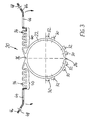
- the tensioning arms 34 preferably each have an area 40, in particular a meandering shape (see FIG. 3). In this area 40, each clamping arm 34 preferably runs back and forth in a meandering or zigzag shape in the radial direction.
- each clamping arm 34 preferably has in its end region a fastening opening 44 which can be suspended on a hook extension 42 of the support frame wall 10 (can be seen in FIG. 3).
- at least one of the tensioning arms 34, but preferably each tensioning arm 34 has an end grip tab 46, which can be gripped in particular with a suitable tool, for example a pair of pliers, for tensioning and hanging. It is also advantageous if the grip tab 46 has an eyelet-like hole opening 48 for the tool (see also FIG. 3).
- Each clamping element 20 is preferably formed as a one-piece molded part (eg injection molded part) made of plastic, and in particular from polyoxymethylene (POM), because this material is characterized by high strength and rigidity on the one hand and on the other hand also has good elasticity.
- molded part eg injection molded part
- POM polyoxymethylene
- the invention is not limited to the exemplary embodiments shown and described, but also encompasses all embodiments having the same effect in the sense of the invention. Furthermore, the invention has not yet been limited to the combination of features defined in claim 1, but can also be defined by any other combination of specific features of all the individual features disclosed in total. This means that in principle practically every single feature of claim 1 can be omitted or replaced by at least one single feature disclosed elsewhere in the application. In this respect, claim 1 is only to be understood as a first attempt at formulation for an invention.
Landscapes
- Engineering & Computer Science (AREA)
- Power Engineering (AREA)
- Motor Or Generator Frames (AREA)
- Dry Shavers And Clippers (AREA)
- Lock And Its Accessories (AREA)
Abstract
Description
Die vorliegende Erfindung betrifft eine Vorrichtung zur Halterung eines Elektromotors in einem Traggestell, wobei der Elektromotor zumindest auf einer Axialseite mit einem statorseitigen, axialen Lageransatz mittelbar über ein auf dem Lageransatz sitzendes, elastisches Aufnahmeelement an einer zur Motorachse zumindest annähernd senkrechten Wandung des Traggestells gehalten ist.The present invention relates to a device for holding an electric motor in a support frame, the electric motor being held at least on one axial side with a stator-side, axial bearing shoulder indirectly via an elastic receiving element seated on the bearing shoulder on a wall of the supporting frame that is at least approximately perpendicular to the motor axis.
Eine derartige Halterungsvorrichtung ist aus der DE-PS 1 175 785 bekannt. Dabei sitzt der Motor mit dem statorseitigen, zylindrischen Lageransatz in dem elastischen, ein Schwingelement zur Schwingungsdämpfung bildenden Aufnahmeelement, welches seinerseits an einem Haltebock des Traggestells gehaltert ist. Über die Art dieser Halterung ist jedoch nichts genaueres offenbart. Offensichtlich sitzt das Schwingelement mit einer Außenringnut direkt in einer Öffnung des Haltebockes, woraus eine schwierige bzw. zeitaufwendige Montage resultiert. Außerdem dürfte die Fixierung des Motors insbesondere in axialer Richtung unzureichend sein.Such a mounting device is known from DE-PS 1 175 785. The motor with the stator-side, cylindrical bearing boss sits in the elastic receiving element which forms a vibration element for vibration damping and which in turn is held on a support bracket of the supporting frame. However, nothing more is disclosed about the type of this holder. Obviously, the oscillating element sits with an outer ring groove directly in an opening of the support bracket, which results in a difficult or time-consuming assembly. In addition, the fixation of the motor should be insufficient, especially in the axial direction.
Der vorliegenden Erfindung liegt die Aufgabe zugrunde, eine Halterungsvorrichtung der gattungsgemäßen Art zu schaffen, die eine einfache und schnelle Montage bei gleichzeitig optimaler Motor-Fixierung in allen Raumrichtungen sowie bei geringem Herstellungsaufwand ermöglicht.The present invention has for its object to provide a mounting device of the generic type that enables simple and quick assembly with optimal motor fixation in all directions in space and with low manufacturing costs.
Erfindungsgemäß wird dies dadurch erreicht, daß das elastische Aufnahmeelement in einer zur Motorachse koaxialen, etwa halbkreisförmigen, einseitig randoffenen Aufnahmeöffnung der Wandung des Traggestells sitzt und durch ein Spannelement in axialer und radialer Richtung in der Aufnahmeöffnung fixiert ist.This is achieved according to the invention in that the elastic receiving element is seated in a receiving opening of the wall of the supporting frame which is coaxial with the motor axis, approximately semicircular, and has one edge open at the edge and is fixed in the receiving opening in the axial and radial direction by a tensioning element.
Durch diese vorteilhafte Ausgestaltung braucht zur Montage lediglich das elastische Aufnahmeelement axial auf den Lageransatz aufgesetzt, dann das Aufnahmeelement in radialer Richtung in die randoffene Aufnahmeöffnung eingesetzt und schließlich mit dem erfindungsgemäßen Spannelement fixiert zu werden. Dabei wird durch eine vorteilhafte, im folgenden noch genauer erläuterte Ausgestaltung des Spannelementes eine gute Fixierung des Aufnahmelementes relativ zu dem Traggestell in allen Raumrichtungen (axial und radial) erreicht, wobei auch die Montage sehr einfach und schnell durchführbar ist. Zudem ist das Spannelement vorteilhafterweise als Kunststoff-Formteil sehr preiswert herstellbar, und zwar bevorzugt aus Polyoxymethylen (POM). Dieses Material zeichnet sich einerseits durch eine hohe Festigkeit und Steifigkeit sowie andererseits ein gutes elastisches Federungsvermögen aus.Due to this advantageous embodiment, only the elastic receiving element needs to be placed axially on the bearing shoulder for assembly, then the receiving element is inserted in the radial direction into the open-ended receiving opening and finally fixed with the tensioning element according to the invention. In this case, an advantageous fixation of the receiving element relative to the support frame in all spatial directions (axial and radial) is achieved by an advantageous configuration of the tensioning element, which is explained in more detail below, and the assembly can also be carried out very easily and quickly. In addition, the clamping element can advantageously be produced very inexpensively as a plastic molded part, preferably from polyoxymethylene (POM). This material is characterized on the one hand by its high strength and rigidity and on the other hand by its good elastic resilience.
Die erfindungsgemäße Halterungsvorrichtung eignet sich insbesondere zur Halterung eines Innenläufermotors in einem etwa C-förmigen Traggestell, wobei der Innenläufermotor zwei einander axial abgekehrte, statorseitige, im wesentlichen gleich ausgebildete Lageransätze aufweist, die jeweils gleichartig in einer von zwei axial entsprechend der Länge des Motors beabstandeten Aufnahmeöffnungen von zwei etwa parallelen Wandungen des Traggestells über jeweils ein elastisches Aufnahmeelement und mittels jeweils eines Spannelementes gehalten sind. Der Motor ist hierbei zwischen den beiden Halterungen axial optimal fixiert. Diese Ausführung eignet sich dann sehr gut für sogenannte "Fan-Coils", wobei es sich um Ventilatoren mit einem mittig angeordneten Motor mit beidseitig herausgeführter Welle handelt, wobei auf jedem Wellenende ein Lüfterrad angebracht ist. Derartige Ventilatoren werden insbesondere für Klimaanlagen verwendet.The mounting device according to the invention is particularly suitable for mounting an internal rotor motor in an approximately C-shaped support frame, the internal rotor motor has two axially facing, stator-side, substantially identical bearing approaches, each of which is held in the same manner in one of two axially spaced-apart receiving openings of two approximately parallel walls of the support frame, each via an elastic receiving element and by means of a respective clamping element. The motor is optimally fixed axially between the two brackets. This design is then very well suited for so-called "fan coils", which are fans with a centrally arranged motor with a shaft which is led out on both sides, a fan wheel being attached to each shaft end. Such fans are used in particular for air conditioning systems.
Die Erfindung eignet sich allerdings grundsätzlich auch für Außenläufermotoren, wobei dann auf der Statorseite die erfindungsgemäße Halterungsvorrichtung und anderseitig eine übliche Lagerung der rotierenden Motorwelle vorgesehen sein kann.However, the invention is fundamentally also suitable for external rotor motors, in which case the mounting device according to the invention can be provided on the stator side and a conventional mounting of the rotating motor shaft can be provided on the other side.
Weitere vorteilhafte Ausgestaltungsmerkmale der Erfindung sind in den Unteransprüchen sowie der folgenden Beschreibung enthalten.Further advantageous design features of the invention are contained in the subclaims and the following description.
Anhand eines in der Zeichnung veranschaulichten, bevorzugten Ausführungsbeispiels soll nun die Erfindung näher erläutert werden. Dabei zeigen:
- Fig. 1
- eine teil-axialgeschnittene Seitenansicht eines über eine erfindungsgemäße Halterungsvorrichtung in einem Traggestell gehalterten Elektromotors (Teilschnitt in der Schnittebene I-I in Fig. 2),
- Fig. 2
- eine längs der Schnittlinie II-II in Fig. 1 teilgeschnittene Stirnansicht und
- Fig. 3
- eine teilgeschnittene, axiale Ansicht eines erfindungsgemäßen Spannelementes.
- Fig. 1
- 2 shows a partially axially sectioned side view of an electric motor which is held in a support frame by means of a holding device according to the invention (partial section in the sectional plane II in FIG. 2),
- Fig. 2
- a along the section line II-II in Fig. 1 and partially cut end view
- Fig. 3
- a partially sectioned, axial view of a clamping element according to the invention.
Gemäß Fig. 1 und 2 ist ein Elektromotor 1 über eine erfindungsgemäße Halterungsvorrichtung in einem Traggestell 4 (sog. "Motorkonsole") gehaltert. Im dargestellten, bevorzugten Ausführungsbeispiel handelt es sich bei dem Elektromotor 1 um einen Innenläufermotor, der zwei statorseitige, axiale, in entgegengesetzte Richtungen weisende, im wesentlichen zylindrische Lageransätze 6 (sog. Lagerschilde) aufweist (s. Fig. 1). Innerhalb der Lageransätze 6 sind nicht dargestellte Lager zur Rotationslagerung eines ebenfalls nicht erkennbaren Rotors angeordnet, wobei der Rotor 2 in entgegengesetzte Richtungen weisende, nach außen geführte Wellenenden 8 aufweist, auf denen beispielsweise jeweils ein nicht dargestelltes Lüfterrad montiert werden kann (sog. "Fan-Coil"). Bei dem Motor 1 kann es sich zudem mit Vorteil um einen jochbewickelten Motor handeln, dessen Statorwicklungen vollständig in Kunststoff eingegossen sind. Die Lageransätze bestehen bevorzugt aus Blechstanzteilen und sind jeweils an ihrem etwa kreisförmigen Umfangsrand vorzugsweise mit dem Kunststoff-Umguß der Statorwicklungen vergossen.1 and 2, an electric motor 1 is held in a support frame 4 (so-called “motor console”) by means of a mounting device according to the invention. In the preferred embodiment shown, the electric motor 1 is an internal rotor motor which has two stator-side, axial, in opposite directions, essentially cylindrical bearing lugs 6 (so-called bearing plates) (see FIG. 1). Bearings (not shown) are arranged within the
Das Traggestell 4 besteht aus zwei etwa parallelen, zur Motorachse 9 etwa senkrechten Wandungen 10 sowie einem diese "bügelartig" verbindenden Basisteil 12, wobei der Motor 1 zwischen den Wandungen 10 gehaltert wird.The support frame 4 consists of two approximately
Hierzu wird bevorzugt auf jeden Lageransatz 6 ein aus einem elastischen, schwingüngsdämpfenden Material (z.B. Gummi) bestehendes Aufnahmeelement 14 axial aufgesetzt, wobei jedes Aufnahmeelement 14 bevorzugt kappenartig mit einem den Lageransatz 6 umfänglich umschließenden Umfangsabschnitt 14a und einem den Lageransatz 6 stirnendseitig umgreifenden, insbesondere eine zentrische Durchführöffnung 16 für das jeweilige Wellenende 8 aufweisenden Wandungsabschnitt 14b ausgebildet ist.For this purpose, a receiving
Erfindungsgemäß ist nun vorgesehen, daß jedes elastische Aufnahmeelement 14 in einer zur Motorachse 9 koaxialen, etwa halbkreisförmigen, einseitig in radialer Richtung randoffenen Aufnahmeöffnung 18 einer der Wandungen 10 des Traggestells 4 sitzt und dabei durch ein Spannelement 20 in axialer sowie radialer Richtung in der Aufnahmeöffnung 18 fixiert ist.According to the invention, it is now provided that each elastic receiving
Wie sich nun durch Zusammenschau der Zeichnungsfiguren 1 bis 3 leicht nachvollziehen läßt, sitzt jedes Spannelement 20 bevorzugt mit einem Ringteil 22 derart in einer äußeren Ringnut 24 des zugehörigen Aufnahmeelementes 14, daß der Ringteil 22 relativ zu dem Aufnahmeelement 14 in axialer Richtung fixiert ist (abgesehen von einem geringen axialen Spiel). Der Ringteil 22 weist zweckmäßigerweise in seinem innerhalb der Aufnahmeöffnung 18 sitzenden Umfangsbereich einen seinen Umfangsverlauf unterbrechenden Schlitz 26 auf. Hierdurch ist der Ringteil 22 zur Montage, d.h. zum Aufsetzen auf das Aufnahmeelement 14, elastisch aufweitbar, so daß er auf einfache Weise in die Ringnut 24 eingesetzt werden kann. Sitzt aber das Aufnahmeelement 14 zusammen mit dem Ringteil 22 einmal in der Aufnahmeöffnung 18 der Wandung 10 des Traggestells 4, so ist der Ringteil 22 gegen Aufweiten durch die Aufnahmeöffnung 18 fixiert. Hierzu ist es besonders vorteilhaft, wenn der Schlitz 26 im Bereich der Symmetrieachse (vertikale Achse 28 in Fig. 2) der Aufnahmeöffnung 18 angeordnet ist. Der Ringteil 22 sitzt dann in axialer Richtung fixiert innerhalb der Ringnut 24, so daß axiale Relativbewegungen zwischen dem Aufnahmeelement 14 und dem Spannelement 20 weitgehend ausgeschlossen sind.As can be easily understood by looking at the drawing figures 1 to 3, each
Zur Fixierung des Spannelementes 20 bzw. dessen Ringteils 22 relativ zu dem Traggestell 4 ist nun bevorzugt vorgesehen, daß der Ringteil 22 in seinem in die Aufnahmeöffnung 18 eingreifenden Umfangsbereich mindestens zwei radial nach außen abstehende und derart um die Dicke der Wandung 10 des Traggestells 4 axial beabstandet angeordnete Fixieransätze 30, 32 aufweist, daß die Wandung 10 mit dem an die Aufnahmeöffnung angrenzenden Bereich zwischen die Fixieransätze 30,32 eingreift, so daß der Ringteil 22 relativ zu der zwischen die Fixieransätze 30,32 eingreifenden Wandung 10 in axialer Richtung fixiert ist (abgesehen von eventuellem geringem Spiel).To fix the
Wie sich insbesondere aus Fig. 3 ergibt, sind in dem bevorzugten Ausführungsbeispiel mehrere, und zwar insbesondere vier, Paare von jeweils zwei axial beabstandeten Fixieransätzen 30,32 vorgesehen, wobei diese Paare über den etwa halbkreisförmigen Umfang der Aufnahmeöffnung 18 verteilt angeordnet sind, und wobei vorzugsweise die beiden Fixieransätze 30,32 jedes Paares relativ zueinander in Umfangsrichtung geringfügig versetzt angeordnet sind. Im dargestellten Ausführungsbeispiel beträgt dieser Versatz etwa 10° bis 20°, insbesondere etwa 15°.3, in the preferred embodiment several, in particular four, pairs of two axially spaced
Für die Fixierung in radialer bzw. zur Motorachse 9 senkrechter Richtung weist jedes Spannelement 20 bevorzugt zwei elastische Spannarme 34 auf, die einstückig mit dem Ringteil 22 verbunden sind, und zwar vorzugsweise an einer dem Schlitz 26 diametral gegenüberliegenden Anbindungsstelle 36 des Ringteil-Außenumfanges. Die Spannarme 34 sind gemäß Fig. 3 zunächst, d.h. vor der Montage, etwa tangential zum Ringteil 22 angeordnet. Zur Montage erfolgt dann eine elastische Verformung der Spannarme 34 um den Außenumfang des Ringteils 22 herum in Richtung der Wandung 10 des Traggestells 4. Somit sind die Spannarme 34 insbesondere unter elastischer Längsdehnung in entgegengesetzten Umfangsrichtungen führbar und dann jeweils über eine Hakenverbindung 38 (siehe Fig. 2) mit der Wandung 10 des Traggestells 4 verbindbar. Für ihre elastische Dehnbarkeit weisen die Spannarme 34 bevorzugt jeweils einen insbesondere mäanderförmig verlaufenden Bereich 40 auf (s. Fig. 3). Dabei verläuft in diesem Bereich 40 jeder Spannarm 34 vorzugsweise in radialer Richtung mäander- bzw. zickzackförmig hin und her. Zur Befestigung am Traggestell 4 weist jeder Spannarm 34 bevorzugt in seinem Endbereich eine auf einen Hakenansatz 42 der Traggestell-Wandung 10 aufhängbare Befestigungsöffnung 44 auf (in Fig. 3 erkennbar). Zudem ist es vorteilhaft, wenn zumindest einer der Spannarme 34, vorzugsweise aber jeder Spannarm 34, eine endseitige Grifflasche 46 aufweist, die insbesondere mit einem geeigneten Werkzeug, beispielsweise einer Zange, zum Spannen und Aufhängen ergreifbar ist. Dabei ist es zudem vorteilhaft, wenn die Grifflasche 46 eine ösenartige Lochöffnung 48 für das Werkzeug aufweist (s. ebenfalls Fig. 3).For fixation in the radial direction or perpendicular to the motor axis 9, each
Jedes Spannelement 20 ist bevorzugt als einstückiges Formteil (z.B. Spritzgießteil) aus Kunststoff gebildet, und zwar insbesondere aus Polyoxymethylen (POM), da sich dieses Material einerseits durch eine hohe Festigkeit und Steifigkeit auszeichnet und andererseits auch ein gutes Federungsvermögen besitzt.Each
Die Montage ist aufgrund der erfindungsgemäßen Halterungsvorrichtung 2 außerordentlich einfach und schnell durchführbar. Der vormontierte, d.h. mit den elastischen Aufnahmeelementen 14 und den Spannelementen 20 versehene Motor 1 braucht lediglich aus radialer Richtung in die Aufnahmeöffnungen 18 eingesetzt zu werden, und zwar so, daß die Wandungen 10 jeweils zwischen die Fixieransätze 30 und 32 eingreifen. Es wird dann jeweils einer der beiden Spannarme 34 mit der Befestigungsöffnung 44 auf den Hakenansatz 42 gehängt. Anschließend wird der jeweils zweite Spannarm 34 insbesondere mittels eines geeigneten Werkzeuges erfaßt und unter leichtem Zug herumgeführt und mit der Befestigungsöffnung 44 auf den Hakenansatz 42 aufgehängt. Auf diese Weise ist dann der Motor 1 bereits sicher positioniert und fixiert.Due to the
Die Erfindung ist nicht auf die dargestellten und beschriebenen Ausführungsbeispiele beschränkt, sondern umfaßt auch alle im Sinne der Erfindung gleichwirkenden Ausführungen. Ferner ist die Erfindung bislang auch noch nicht auf die im Anspruch 1 definierte Merkmalskombination beschränkt, sondern kann auch durch jede beliebige andere Kombination von bestimmten Merkmalen aller insgesamt offenbarten Einzelmerkmalen definiert sein. Dies bedeutet, daß grundsätzlich praktisch jedes Einzelmerkmal des Anspruchs 1 weggelassen bzw. durch mindestens ein an anderer Stelle der Anmeldung offenbartes Einzelmerkmal ersetzt werden kann. Insofern ist der Anspruch 1 lediglich als ein erster Formulierungsversuch für eine Erfindung zu verstehen.The invention is not limited to the exemplary embodiments shown and described, but also encompasses all embodiments having the same effect in the sense of the invention. Furthermore, the invention has not yet been limited to the combination of features defined in claim 1, but can also be defined by any other combination of specific features of all the individual features disclosed in total. This means that in principle practically every single feature of claim 1 can be omitted or replaced by at least one single feature disclosed elsewhere in the application. In this respect, claim 1 is only to be understood as a first attempt at formulation for an invention.
Claims (11)
dadurch gekennzeichnet, daß das elastische Aufnahmeelement (14) in einer zur Motorachse (9) koaxialen, etwa halbkreisförmigen, einseitig randoffenen Aufnahmeöffnung (18) der Wandung (10) des Traggestells (4) sitzt und durch ein Spannelement (20) in axialer und radialer Richtung in der Aufnahmeöffnung (18) fixiert ist.Device for holding an electric motor (1) in a support frame (4), the electric motor (1) at least on one axial side with a stator-side, axial bearing boss (6) indirectly via an elastic receiving element (14) seated on the bearing boss (6) is held on a wall (10) of the supporting frame (4),
characterized in that the resilient receiving element (14) is seated in a receiving opening (18) of the wall (10) of the support frame (4) which is coaxial with the motor axis (9), approximately semicircular and open on one side at the edge, and by means of a tensioning element (20) in the axial and radial directions Direction in the receiving opening (18) is fixed.
dadurch gekennzeichnet, daß der Elektromotor (1) als Innenläufermotor ausgebildet ist und zwei einander axial abgekehrte, statorseitige, im wesentlichen gleich ausgebildete Lageransätze (6) aufweist, die jeweils gleichartig in einer von zwei axial um die Länge des Motors (1) beabstandeten Aufnahmeöffnungen (18) des Traggestells (4) über jeweils ein elastisches Aufnahmeelement (14) und mittels jeweils eines Spannelementes (20) gehalten sind.Device according to claim 1,
characterized in that the electric motor (1) is designed as an internal rotor motor and has two axially facing, stator-side, substantially identical bearing projections (6), each of the same type in one of two axially by the length of the motor (1) spaced receiving openings (18) of the support frame (4) via an elastic receiving element (14) and by means of a clamping element (20).
dadurch gekennzeichnet, daß das bzw. jedes Spannelement (20) mit einem Ringteil (22) derart in einer äußeren Ringnut (24) des Aufnahmeelementes (14) sitzt, daß der Ringteil (22) relativ zu dem Aufnahmeelement (14) in axialer Richtung fixiert ist, wobei vorzugsweise der Ringteil (22) in seinem in der Aufnahmeöffnung (18) sitzenden Umfangsbereich einen Schlitz (26) aufweist.Device according to claim 1 or 2,
characterized in that the or each clamping element (20) with an annular part (22) sits in an outer annular groove (24) of the receiving element (14) in such a way that the annular part (22) fixes in the axial direction relative to the receiving element (14) The ring part (22) preferably has a slot (26) in its peripheral region seated in the receiving opening (18).
dadurch gekennzeichnet, daß der Ringteil (22) in seinem in die Aufnahmeöffnung (18) eingreifenden Bereich mindestens zwei radial nach außen abstehende und derart um die Dicke der Wandung (10) des Traggestells (4) axial beabstandet angeordnete Fixieransätze (30,32) aufweist, daß der Ringteil (22) relativ zu der zwischen die Fixieransätze (30, 32) eingreifenden Wandung (10) in axialer Richtung fixiert ist.Device according to claim 3,
characterized in that the ring part (22) has in its area engaging in the receiving opening (18) at least two radially outwardly projecting and thus axially spaced by the thickness of the wall (10) of the support frame (4) arranged fixing lugs (30, 32) that the ring part (22) is fixed in the axial direction relative to the wall (10) engaging between the fixing lugs (30, 32).
dadurch gekennzeichnet, daß mehrere, insbesondere vier, Paare von jeweils axial beabstandeten Fixieransätzen (30,32) vorgesehen sind, wobei diese Paare über den etwa halbkreisförmigen Umfang der Aufnahmeöffnung (18) verteilt angeordnet sind, und wobei vorzugsweise die beiden Fixieransätze (30,32) jedes Paares relativ zueinander in Umfangsrichtung versetzt angeordnet sind.Device according to claim 4,
characterized in that several, in particular four, pairs of axially spaced fixing lugs (30, 32) are provided, these pairs being distributed over the approximately semicircular circumference of the receiving opening (18), and preferably the two fixing lugs (30,32) of each pair are circumferentially offset relative to each other.
dadurch gekennzeichnet, daß das bzw. jedes Spannelement (20) zwei elastische Spannarme (34) aufweist, die einstückig mit dem Ringteil (22) verbunden sind, und zwar vorzugsweise an einer dem Schlitz (26) diametral gegenüberliegenden Anbindungsstelle (36) des Ringteil-Außenumfanges, wobei die Spannarme (34) insbesondere unter elastischer Dehnung in entgegengesetzen Umfangsrichtungen führbar und jeweils über eine insbesondere als Hakenverbindung (38) ausgebildete Formschlußverbindung mit der Wandung (10) des Traggestells (4) verbindbar sind.Device according to one or more of claims 3 to 5,
characterized in that the or each clamping element (20) has two elastic clamping arms (34) which are integrally connected to the ring part (22), preferably at a connection point (36) of the ring part diametrically opposite the slot (26). Outer circumference, the tensioning arms (34) being able to be guided in opposite circumferential directions, in particular with elastic expansion, and each being connectable to the wall (10) of the support frame (4) via a form-fit connection, in particular designed as a hook connection (38).
dadurch gekennzeichnet, daß die Spannarme (34) für ihre elastische Dehnbarkeit jeweils einen längselastischen, insbesondere mäanderförmig verlaufenden Bereich (40) aufweisen.Apparatus according to claim 6,
characterized in that the clamping arms (34) each have a longitudinally elastic, in particular meandering region (40) for their elastic extensibility.
dadurch gekennzeichnet, daß jeder Spannarm (34) eine auf einen Hakenansatz (42) der Traggestell-Wandung (10) aufhängbare Befestigungsöffnung (44) aufweist.Apparatus according to claim 6 or 7,
characterized in that each clamping arm (34) has a fastening opening (44) which can be suspended from a hook extension (42) of the supporting frame wall (10).
dadurch gekennzeichnet, daß zumindest einer der Spannarme (34) eine endseitige Grifflasche (46) aufweist.Device according to one or more of claims 6 to 8,
characterized in that at least one of the clamping arms (34) has an end grip tab (46).
dadurch gekennzeichnet, daß das bzw. jedes elastische Aufnahmeelement (14) kappenartig mit einem den Lageransatz (6) umfänglich umschließenden Umfangsabschnitt (14a) und einem den Lageransatz (6) stirnendseitig umgreifenden, insbesondere eine zentrische Durchführöffnung (16) für eine Motorwelle (8) aufweisenden Wandungsabschnitt (14b) ausgebildet ist.Device according to one or more of claims 1 to 9,
characterized in that the or each elastic receiving element (14) is cap-like with a circumferential section (14a) surrounding the bearing shoulder (6) and a peripheral through opening (16) for a motor shaft (8), which surrounds the bearing shoulder (6) having wall section (14b) is formed.
dadurch gekennzeichnet, daß das bzw. jedes Spannelement (20) als einstückiges Formteil aus Kunststoff, insbesondere aus Polyoxymethylen (POM), gebildet ist.Device according to one or more of claims 1 to 10,
characterized in that the or each clamping element (20) is formed as a one-piece molded part made of plastic, in particular of polyoxymethylene (POM).
Applications Claiming Priority (2)
| Application Number | Priority Date | Filing Date | Title |
|---|---|---|---|
| DE9418283U DE9418283U1 (en) | 1994-11-15 | 1994-11-15 | Device for mounting an electric motor |
| DE9418283U | 1994-11-15 |
Publications (3)
| Publication Number | Publication Date |
|---|---|
| EP0713283A2 true EP0713283A2 (en) | 1996-05-22 |
| EP0713283A3 EP0713283A3 (en) | 1996-08-21 |
| EP0713283B1 EP0713283B1 (en) | 2000-12-20 |
Family
ID=6916148
Family Applications (1)
| Application Number | Title | Priority Date | Filing Date |
|---|---|---|---|
| EP95113115A Expired - Lifetime EP0713283B1 (en) | 1994-11-15 | 1995-08-21 | Supporting structure for an electric motor |
Country Status (2)
| Country | Link |
|---|---|
| EP (1) | EP0713283B1 (en) |
| DE (2) | DE9418283U1 (en) |
Cited By (3)
| Publication number | Priority date | Publication date | Assignee | Title |
|---|---|---|---|---|
| GB2313715A (en) * | 1996-05-22 | 1997-12-03 | Electrolux Zanussi Elettrodome | Noise damping mounting of washing machine motor |
| DE10019572A1 (en) * | 2000-04-20 | 2001-10-25 | Behr Gmbh & Co | Holder for motor e.g. for fan in vehicle air conditioning unit, has damping element consisting of sleeve of elastic material surrounding motor housing on periphery, slotted on longitudinal side for radial assembly |
| WO2015158497A3 (en) * | 2014-04-14 | 2016-02-04 | Valeo Systemes Thermiques | Fan motor support |
Families Citing this family (2)
| Publication number | Priority date | Publication date | Assignee | Title |
|---|---|---|---|---|
| AT503033B1 (en) * | 2006-02-13 | 2007-07-15 | Blum Gmbh Julius | DRIVE UNIT FOR MOVABLE FURNITURE PARTS |
| US12034354B2 (en) | 2019-01-04 | 2024-07-09 | Vitesco Technologies USA, LLC | Spring retention system for dc motor |
Citations (1)
| Publication number | Priority date | Publication date | Assignee | Title |
|---|---|---|---|---|
| DE1175785B (en) | 1962-10-20 | 1964-08-13 | Hermann Papst | Mounting and storage of internal or external rotor motors, preferably with torsional vibration support |
Family Cites Families (6)
| Publication number | Priority date | Publication date | Assignee | Title |
|---|---|---|---|---|
| US2296221A (en) * | 1941-04-10 | 1942-09-15 | Gen Motors Corp | Clamp |
| US2729846A (en) * | 1954-01-26 | 1956-01-10 | F Hohlfelder Company | Mounting ring |
| US2803416A (en) * | 1954-06-04 | 1957-08-20 | Gen Electric | Resilient mounting |
| US3235653A (en) * | 1964-01-02 | 1966-02-15 | Gen Electric | Resilient mounting arrangements for rotating machines |
| US3509393A (en) * | 1968-05-07 | 1970-04-28 | Emerson Electric Co | Electric motor having resilient mounting ring with bearing cap |
| DE4121927A1 (en) * | 1991-07-03 | 1993-01-07 | Mulfingen Elektrobau Ebm | DOUBLE SIDED SUCTIONING CENTRIFUGAL FAN |
-
1994
- 1994-11-15 DE DE9418283U patent/DE9418283U1/en not_active Expired - Lifetime
-
1995
- 1995-08-21 DE DE59508907T patent/DE59508907D1/en not_active Expired - Fee Related
- 1995-08-21 EP EP95113115A patent/EP0713283B1/en not_active Expired - Lifetime
Patent Citations (1)
| Publication number | Priority date | Publication date | Assignee | Title |
|---|---|---|---|---|
| DE1175785B (en) | 1962-10-20 | 1964-08-13 | Hermann Papst | Mounting and storage of internal or external rotor motors, preferably with torsional vibration support |
Cited By (7)
| Publication number | Priority date | Publication date | Assignee | Title |
|---|---|---|---|---|
| GB2313715A (en) * | 1996-05-22 | 1997-12-03 | Electrolux Zanussi Elettrodome | Noise damping mounting of washing machine motor |
| GB2313715B (en) * | 1996-05-22 | 2000-09-06 | Electrolux Zanussi Elettrodome | Arrangement for mounting the motor in a clothes washing machine |
| DE10019572A1 (en) * | 2000-04-20 | 2001-10-25 | Behr Gmbh & Co | Holder for motor e.g. for fan in vehicle air conditioning unit, has damping element consisting of sleeve of elastic material surrounding motor housing on periphery, slotted on longitudinal side for radial assembly |
| WO2015158497A3 (en) * | 2014-04-14 | 2016-02-04 | Valeo Systemes Thermiques | Fan motor support |
| CN106233585A (en) * | 2014-04-14 | 2016-12-14 | 法雷奥热系统公司 | Fan electromotor support member |
| CN106233585B (en) * | 2014-04-14 | 2018-12-25 | 法雷奥热系统公司 | Fan motor supporting element |
| US10461603B2 (en) | 2014-04-14 | 2019-10-29 | Valeo Systemes Thermiques | Fan motor support |
Also Published As
| Publication number | Publication date |
|---|---|
| DE59508907D1 (en) | 2001-01-25 |
| EP0713283A3 (en) | 1996-08-21 |
| EP0713283B1 (en) | 2000-12-20 |
| DE9418283U1 (en) | 1996-03-21 |
Similar Documents
| Publication | Publication Date | Title |
|---|---|---|
| DE10131590A1 (en) | Device for fastening an electric motor | |
| DE29706216U1 (en) | Arrangement for the vibration-isolating suspension of an electric motor | |
| DE29900923U1 (en) | Arrangement for the vibration-isolating bracket of an electric motor | |
| WO2004112219A1 (en) | Decoupling device and method for the production of an electric motor | |
| WO2005107041A1 (en) | Electric motor comprising a mounting device | |
| DE19651735A1 (en) | Holder for a motor, in particular an impeller electric motor | |
| DE19839640B4 (en) | Motor with a spherical bearing that can be fixed in a bearing seat with axial play adjustment for a rotor shaft and method for axial play adjustment for a rotor shaft | |
| DE602004006325T2 (en) | Holding device for a fan motor | |
| EP0713283B1 (en) | Supporting structure for an electric motor | |
| DE202013012278U1 (en) | Angle connector with adjustable outlet direction | |
| DE102018212145A1 (en) | Electric motor and pump with such an electric motor | |
| DE102021205499A1 (en) | Drive device and stator assembly therefor | |
| EP3436704B1 (en) | Coolant pump assembly | |
| WO2006021576A1 (en) | Brush holder, preferably for a carbon brush | |
| DE2743651C2 (en) | ||
| DE4405577A1 (en) | Arrangement for the vibration-damped mounting of an electric motor | |
| EP0926803B1 (en) | Device for vibration-isolating mount of a motor | |
| EP0855782B1 (en) | Low noise electric motor, notably for a fan of a motor vehicle | |
| EP1335479B1 (en) | Vibration isolating section for holding an electrical motor | |
| DE9303162U1 (en) | Device for receiving an electric motor | |
| EP1075075B1 (en) | Arrangement for a vibration insulating support of an electric motor | |
| DE4041600A1 (en) | TORSION DAMPER | |
| DE102004015241B4 (en) | Air-cooled electric machine | |
| EP1423032B1 (en) | Kitchen device | |
| DE102004014886B4 (en) | Transport lock for an internal combustion engine |
Legal Events
| Date | Code | Title | Description |
|---|---|---|---|
| PUAI | Public reference made under article 153(3) epc to a published international application that has entered the european phase |
Free format text: ORIGINAL CODE: 0009012 |
|
| AK | Designated contracting states |
Kind code of ref document: A2 Designated state(s): DE ES FR GB IT |
|
| PUAL | Search report despatched |
Free format text: ORIGINAL CODE: 0009013 |
|
| AK | Designated contracting states |
Kind code of ref document: A3 Designated state(s): DE ES FR GB IT |
|
| 17P | Request for examination filed |
Effective date: 19961016 |
|
| RAP1 | Party data changed (applicant data changed or rights of an application transferred) |
Owner name: EBM WERKE GMBH & CO. |
|
| 17Q | First examination report despatched |
Effective date: 19980309 |
|
| GRAG | Despatch of communication of intention to grant |
Free format text: ORIGINAL CODE: EPIDOS AGRA |
|
| 17Q | First examination report despatched |
Effective date: 19980309 |
|
| GRAG | Despatch of communication of intention to grant |
Free format text: ORIGINAL CODE: EPIDOS AGRA |
|
| GRAH | Despatch of communication of intention to grant a patent |
Free format text: ORIGINAL CODE: EPIDOS IGRA |
|
| GRAH | Despatch of communication of intention to grant a patent |
Free format text: ORIGINAL CODE: EPIDOS IGRA |
|
| GRAA | (expected) grant |
Free format text: ORIGINAL CODE: 0009210 |
|
| AK | Designated contracting states |
Kind code of ref document: B1 Designated state(s): DE ES FR GB IT |
|
| PG25 | Lapsed in a contracting state [announced via postgrant information from national office to epo] |
Ref country code: GB Free format text: LAPSE BECAUSE OF FAILURE TO SUBMIT A TRANSLATION OF THE DESCRIPTION OR TO PAY THE FEE WITHIN THE PRESCRIBED TIME-LIMIT Effective date: 20001220 Ref country code: FR Free format text: LAPSE BECAUSE OF FAILURE TO SUBMIT A TRANSLATION OF THE DESCRIPTION OR TO PAY THE FEE WITHIN THE PRESCRIBED TIME-LIMIT Effective date: 20001220 Ref country code: ES Free format text: THE PATENT HAS BEEN ANNULLED BY A DECISION OF A NATIONAL AUTHORITY Effective date: 20001220 |
|
| ITF | It: translation for a ep patent filed | ||
| REF | Corresponds to: |
Ref document number: 59508907 Country of ref document: DE Date of ref document: 20010125 |
|
| EN | Fr: translation not filed | ||
| GBV | Gb: ep patent (uk) treated as always having been void in accordance with gb section 77(7)/1977 [no translation filed] |
Effective date: 20001220 |
|
| PLBE | No opposition filed within time limit |
Free format text: ORIGINAL CODE: 0009261 |
|
| STAA | Information on the status of an ep patent application or granted ep patent |
Free format text: STATUS: NO OPPOSITION FILED WITHIN TIME LIMIT |
|
| 26N | No opposition filed | ||
| PGFP | Annual fee paid to national office [announced via postgrant information from national office to epo] |
Ref country code: DE Payment date: 20041026 Year of fee payment: 10 |
|
| PG25 | Lapsed in a contracting state [announced via postgrant information from national office to epo] |
Ref country code: IT Free format text: LAPSE BECAUSE OF NON-PAYMENT OF DUE FEES Effective date: 20050821 |
|
| PG25 | Lapsed in a contracting state [announced via postgrant information from national office to epo] |
Ref country code: DE Free format text: LAPSE BECAUSE OF NON-PAYMENT OF DUE FEES Effective date: 20060301 |