EP0713017A2 - Vis auto-taraudeuse - Google Patents
Vis auto-taraudeuse Download PDFInfo
- Publication number
- EP0713017A2 EP0713017A2 EP95117144A EP95117144A EP0713017A2 EP 0713017 A2 EP0713017 A2 EP 0713017A2 EP 95117144 A EP95117144 A EP 95117144A EP 95117144 A EP95117144 A EP 95117144A EP 0713017 A2 EP0713017 A2 EP 0713017A2
- Authority
- EP
- European Patent Office
- Prior art keywords
- screw
- flank
- angle
- thread
- tip
- Prior art date
- Legal status (The legal status is an assumption and is not a legal conclusion. Google has not performed a legal analysis and makes no representation as to the accuracy of the status listed.)
- Withdrawn
Links
- 238000010079 rubber tapping Methods 0.000 title claims description 5
- 238000005520 cutting process Methods 0.000 claims description 3
- 241001661918 Bartonia Species 0.000 abstract 1
- 230000007704 transition Effects 0.000 description 12
- 239000011093 chipboard Substances 0.000 description 8
- 239000000463 material Substances 0.000 description 6
- 230000000694 effects Effects 0.000 description 2
- 230000003313 weakening effect Effects 0.000 description 2
- 230000002411 adverse Effects 0.000 description 1
- 238000013459 approach Methods 0.000 description 1
- 238000005336 cracking Methods 0.000 description 1
- 230000007423 decrease Effects 0.000 description 1
- 230000003247 decreasing effect Effects 0.000 description 1
- 230000001771 impaired effect Effects 0.000 description 1
- 238000004519 manufacturing process Methods 0.000 description 1
- 230000008092 positive effect Effects 0.000 description 1
- 238000003825 pressing Methods 0.000 description 1
- 230000035945 sensitivity Effects 0.000 description 1
Images
Classifications
-
- F—MECHANICAL ENGINEERING; LIGHTING; HEATING; WEAPONS; BLASTING
- F16—ENGINEERING ELEMENTS AND UNITS; GENERAL MEASURES FOR PRODUCING AND MAINTAINING EFFECTIVE FUNCTIONING OF MACHINES OR INSTALLATIONS; THERMAL INSULATION IN GENERAL
- F16B—DEVICES FOR FASTENING OR SECURING CONSTRUCTIONAL ELEMENTS OR MACHINE PARTS TOGETHER, e.g. NAILS, BOLTS, CIRCLIPS, CLAMPS, CLIPS OR WEDGES; JOINTS OR JOINTING
- F16B25/00—Screws that cut thread in the body into which they are screwed, e.g. wood screws
- F16B25/0036—Screws that cut thread in the body into which they are screwed, e.g. wood screws characterised by geometric details of the screw
- F16B25/0042—Screws that cut thread in the body into which they are screwed, e.g. wood screws characterised by geometric details of the screw characterised by the geometry of the thread, the thread being a ridge wrapped around the shaft of the screw
- F16B25/0047—Screws that cut thread in the body into which they are screwed, e.g. wood screws characterised by geometric details of the screw characterised by the geometry of the thread, the thread being a ridge wrapped around the shaft of the screw the ridge being characterised by its cross-section in the plane of the shaft axis
-
- F—MECHANICAL ENGINEERING; LIGHTING; HEATING; WEAPONS; BLASTING
- F16—ENGINEERING ELEMENTS AND UNITS; GENERAL MEASURES FOR PRODUCING AND MAINTAINING EFFECTIVE FUNCTIONING OF MACHINES OR INSTALLATIONS; THERMAL INSULATION IN GENERAL
- F16B—DEVICES FOR FASTENING OR SECURING CONSTRUCTIONAL ELEMENTS OR MACHINE PARTS TOGETHER, e.g. NAILS, BOLTS, CIRCLIPS, CLAMPS, CLIPS OR WEDGES; JOINTS OR JOINTING
- F16B25/00—Screws that cut thread in the body into which they are screwed, e.g. wood screws
- F16B25/001—Screws that cut thread in the body into which they are screwed, e.g. wood screws characterised by the material of the body into which the screw is screwed
- F16B25/0015—Screws that cut thread in the body into which they are screwed, e.g. wood screws characterised by the material of the body into which the screw is screwed the material being a soft organic material, e.g. wood or plastic
-
- F—MECHANICAL ENGINEERING; LIGHTING; HEATING; WEAPONS; BLASTING
- F16—ENGINEERING ELEMENTS AND UNITS; GENERAL MEASURES FOR PRODUCING AND MAINTAINING EFFECTIVE FUNCTIONING OF MACHINES OR INSTALLATIONS; THERMAL INSULATION IN GENERAL
- F16B—DEVICES FOR FASTENING OR SECURING CONSTRUCTIONAL ELEMENTS OR MACHINE PARTS TOGETHER, e.g. NAILS, BOLTS, CIRCLIPS, CLAMPS, CLIPS OR WEDGES; JOINTS OR JOINTING
- F16B25/00—Screws that cut thread in the body into which they are screwed, e.g. wood screws
- F16B25/0036—Screws that cut thread in the body into which they are screwed, e.g. wood screws characterised by geometric details of the screw
- F16B25/0042—Screws that cut thread in the body into which they are screwed, e.g. wood screws characterised by geometric details of the screw characterised by the geometry of the thread, the thread being a ridge wrapped around the shaft of the screw
- F16B25/0073—Screws that cut thread in the body into which they are screwed, e.g. wood screws characterised by geometric details of the screw characterised by the geometry of the thread, the thread being a ridge wrapped around the shaft of the screw characterised by its pitch, e.g. a varying pitch
Definitions
- the invention relates to a self-tapping screw, in particular for use as a chipboard screw, with a screw head with a drive device, an essentially cylindrical screw shaft, on which a single thread is formed from threads, and a screw tip.
- Screws of this type are well known in the art. A particular advantage of their application is that no pre-drilled guide hole is required to screw in such screws.
- the specialization in a specific application, here on a chipboard screw, results in comparison with so-called universal screws, the properties of which always compromise the required different applications, the advantage that their features can be designed so that the performance of the screw for this use case can be optimized.
- the characteristics of a screw that determine its performance are in particular the profile shape, the type of thread, the flank angle, the depth of cut ratio and the pitch.
- the performance of a screw, such as the feed, screw-in resistance and pull-out force are significantly influenced by the selection of the values of these parameters.
- An increase in the depth of cut ratio generally increases the pull-out force, while at the same time (assuming a constant nominal diameter) the screw strength decreases due to the decreasing core diameter.
- chipboard low density, tendency to crumble, sensitivity to cracking, etc.
- chipboard low density, tendency to crumble, sensitivity to cracking, etc.
- a small thread pitch is aimed for.
- a low screw-in resistance is also supported by a small flank angle of the thread.
- a small flank angle also increases the pull-out force of the screw.
- the object of the invention is therefore to provide an improved self-tapping screw, in particular for use as a chipboard screw, the design of which enables improved performance to be achieved with regard to screwing-in time, screw-in resistance and pull-out force.
- the double-angle profile has a flank with a straight outer contour on the screw tip side and two flank sections with an obtuse angle each with a straight outer contour on the screw head side, of which the screw shank side flank section includes a larger angle than the flank section with a plane perpendicular to the longitudinal axis of the screw (radial plane).
- the double-angle profile has a flank angle ⁇ of 30 ° ⁇ 5 ° enclosed by the screw tip side flank and the thread tip side flank section, an angle ⁇ of 25 ° ⁇ 5 ° included by the screw tip side flank and a radial plane of the screw angle ⁇ of 25 ° ⁇ 5 ° and / or an angle ⁇ of 5 ° ⁇ 5 ° enclosed by the thread-side flank section and a radial plane of the screw.
- the screw is also provided with threads in the area of the screw tip, which threads either have a double-angle profile or a single-angle profile.
- An angled profile (symmetrical or asymmetrical) is preferred for the area of the screw tip.
- the threads in the area of the screw tip have a flank angle of preferably approximately 50 °.
- the thread has a pitch ratio P / D of 0.63 ⁇ 0.03 and / or a cutting depth ratio D / d of 1.6 ⁇ 0.05.
- the terms “profile” and “outer contour” refer to the thread profile, as is the case with a longitudinal section through the longitudinal axis of the screw.
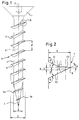
- a self-tapping screw 10 according to the invention, in particular for use as a chipboard screw, which consists of a screw head 1 designed as a countersunk head with drive devices 2 in the form of an internal polygon as well as a screw shaft 3 provided with threads 5, 5a and a screw tip 4.
- the thread formed by the threads 5, 5a is a single-start thread.
- the threads 5 In the area of the screw shaft 3, the threads 5 have a double-angle profile 7, as shown in FIG. 2.
- the screw has a core diameter d and a nominal diameter D, the thread pitch is denoted by P, and the flank angle of the double angle profile bears the reference symbol ⁇ .
- the double angle profile has a continuous flank 20 on the screw tip side with a straight outer contour, which includes an angle ⁇ of approximately 25 ° with a plane (radial plane) perpendicular to the longitudinal axis 6 of the screw.
- the double angle profile On the screw head side, the double angle profile has two obtuse-angled flank sections 22, 24, each with a rectilinear outer contour, of which the flank section 24 on the screw shank side encloses an angle ⁇ of approximately 25 ° with a radial plane of the screw, while the flank section 22 on the tip side of the thread has an angle ⁇ with a radial plane of the screw of about 5 °.
- the screw tip side flank 20 and the screw shaft side flank section 24 are symmetrical to one another with respect to a radial plane E of the screw, which divides the distance between the transition of the screw tip side flank and the transition of the screw shaft side flank section into the shaft into two equal sections. From the angle values given above it also follows that at a preferred embodiment of the flank angle ⁇ at the thread tip 8 is approximately 30 °.
- the selected double angle profile offers a number of advantages. Since the angles ⁇ at the transition of the thread flanks in the screw shank correspond to those of a symmetrical thread with a flank angle of 50 °, the transition is not sharp-edged, which on the one hand prevents the screw from weakening and on the other prevents the material into which the screw is screwed is screwed in, is cut with sharp edges in this area.
- the additional pressing effect on the material by the flank section on the screw shaft side results in advantages with regard to the pull-out force of the screw.
- the screw according to the invention has a substantially increased depth of cut ratio D / d, which further has a positive effect on the pull-out force.
- the pull-out force is finally positively influenced by the angle ⁇ , which the thread-side flank section encloses with a radial plane. This angle corresponds approximately to that of an asymmetrical thread profile of conventional screws.
- An essential parameter in the design of such a screw according to the invention is the distance X between the radial plane through the thread tip 8 and the radial plane E, which leads through the intersection of the screw tip side flank 20 with an imaginary straight extension of the screw shaft side flank section 24 and the distance between the transition the screw tip side flank and the transition of the screw shaft side flank section into the shaft (as already explained above) divided into two equal parts.
- This distance X is maximum for the extreme case in which the length of the flank section 24 on the screw shaft side approaches 0, that is to say the profile according to the invention to a conventional asymmetrical profile with a flank angle of approximately 30 ° degenerate.
- This distance X becomes minimal and becomes 0 if the length of the flank section 24 on the screw shaft side becomes equal to the length of the flank 20 on the screw tip side, ie the double-angle profile according to the invention degenerates into a conventional symmetrical screw profile with a flank angle of approximately 50 °.
- a thread pitch ratio P / D of 0.63 ⁇ 0.03 is selected, which is approximately 1.4 times the pitch ratio of 0.40 - 0.45, which is common for chipboard screws with single-threaded threads.
- the lower screw-in resistance of the double-angle profile according to the invention compared to conventional screws absorbs the increase in screw-in resistance due to the higher thread pitch compared to conventional screws.
- the depth of cut ratio D / d selected for the screw of this embodiment of approximately 1.6 makes it possible to achieve a high pull-out force, while at the same time the screw strength is not impaired due to the non-sharp-edged transition of the thread flanks into the screw shaft.
- the screw thread in the area of the screw tip does not have a double-angle profile, but rather a single-angle profile with a flank angle of approximately 50 °, which, together with the thread pitch P increased by approximately 40% compared to conventional screws, results in a quick gripping of the first threads.
Applications Claiming Priority (2)
| Application Number | Priority Date | Filing Date | Title |
|---|---|---|---|
| DE19944439535 DE4439535A1 (de) | 1994-11-04 | 1994-11-04 | Selbstschneidende Schraube |
| DE4439535 | 1994-11-04 |
Publications (2)
| Publication Number | Publication Date |
|---|---|
| EP0713017A2 true EP0713017A2 (fr) | 1996-05-22 |
| EP0713017A3 EP0713017A3 (fr) | 1996-06-12 |
Family
ID=6532554
Family Applications (1)
| Application Number | Title | Priority Date | Filing Date |
|---|---|---|---|
| EP95117144A Withdrawn EP0713017A2 (fr) | 1994-11-04 | 1995-10-31 | Vis auto-taraudeuse |
Country Status (2)
| Country | Link |
|---|---|
| EP (1) | EP0713017A2 (fr) |
| DE (1) | DE4439535A1 (fr) |
Cited By (7)
| Publication number | Priority date | Publication date | Assignee | Title |
|---|---|---|---|---|
| EP0887563A1 (fr) * | 1997-06-20 | 1998-12-30 | Adolf Würth GmbH & Co. KG | Vis pour montage de garniture |
| WO2001044672A1 (fr) | 1999-12-14 | 2001-06-21 | Ejot Verbindungstechnik Gmbh & Co. Kg | Vis autotaraudeuse |
| EP1219840A1 (fr) * | 2000-12-22 | 2002-07-03 | HILTI Aktiengesellschaft | Vis auto-taraudeuse |
| DE102004011668B3 (de) * | 2004-03-10 | 2005-10-13 | Hans Schriever Gmbh & Co. Kg | Selbstfurchende Schraube |
| JP2010223257A (ja) * | 2009-03-19 | 2010-10-07 | Nitto Seiko Co Ltd | ねじ部品 |
| DE102010032956A1 (de) * | 2010-07-30 | 2012-02-02 | EAV UG (haftungsbeschränkt) | Montageschiene mit einer Längsnut und Anordnung mit einer Schraube und einer derartigen Montageschiene |
| EP3875790A1 (fr) * | 2020-03-06 | 2021-09-08 | Günter Weippert | Vis |
Families Citing this family (7)
| Publication number | Priority date | Publication date | Assignee | Title |
|---|---|---|---|---|
| EP0927309B1 (fr) * | 1997-07-29 | 2003-01-08 | EJOT VERBINDUNGSTECHNIK GmbH & Co. KG | Vis avec filetage a rainurage automatique |
| US9482258B2 (en) | 2012-05-10 | 2016-11-01 | Simpson Strong-Tie Company, Inc. | Fastener with multiple threaded regions |
| US9651079B2 (en) | 2013-03-21 | 2017-05-16 | Simpson Strong-Tie Company, Inc. | Fastener with prolate cross-section |
| US11181138B2 (en) | 2013-03-26 | 2021-11-23 | Simpson Strong-Tie Company, Inc. | Variable thread knurl fastener |
| US9523383B2 (en) | 2013-03-26 | 2016-12-20 | Simpson Strong-Tie Company, Inc. | Variable thread fastener |
| AU2015321710B2 (en) * | 2014-09-22 | 2019-09-12 | Simpson Strong-Tie Company, Inc. | Variable thread fastener |
| DE102014219116A1 (de) * | 2014-09-23 | 2016-03-24 | Toge Dübel Gmbh & Co. Kg | Selbstschneidende Schraube zum Einschrauben in ein Bohrloch in einem Werkstoff, Anordnung mit einer derartigen Schraube und Verfahren zum Einschrauben einer derartigen Schraube in ein Bohrloch |
Citations (7)
| Publication number | Priority date | Publication date | Assignee | Title |
|---|---|---|---|---|
| US4171012A (en) * | 1975-11-25 | 1979-10-16 | Holmes Horace D | Locking thread construction |
| DE8409108U1 (de) * | 1984-07-19 | Schrauben Betzer KG, 5880 Lüdenscheid | Gewindeformende Schraube | |
| EP0133773A1 (fr) * | 1983-08-04 | 1985-03-06 | Illinois Tool Works Inc. | Elément de fixation comportant un filetage |
| US4536117A (en) * | 1981-11-30 | 1985-08-20 | Mid-Continent Screw Products Company | Screw fastener |
| EP0207862A1 (fr) * | 1985-07-05 | 1987-01-07 | LAURENT INDUSTRIE S.A. Société dite: | Tige filetée, telle qu'une vis, et son procédé de fabrication |
| DE3615271A1 (de) * | 1986-05-06 | 1987-11-12 | Thomas Mueller | Schraube fuer kunststoff-spreizduebel |
| EP0504782A1 (fr) * | 1991-03-18 | 1992-09-23 | Adolf Würth GmbH & Co. KG | Vis, procédé et matrice de laminage pour sa fabrication |
-
1994
- 1994-11-04 DE DE19944439535 patent/DE4439535A1/de not_active Withdrawn
-
1995
- 1995-10-31 EP EP95117144A patent/EP0713017A2/fr not_active Withdrawn
Patent Citations (7)
| Publication number | Priority date | Publication date | Assignee | Title |
|---|---|---|---|---|
| DE8409108U1 (de) * | 1984-07-19 | Schrauben Betzer KG, 5880 Lüdenscheid | Gewindeformende Schraube | |
| US4171012A (en) * | 1975-11-25 | 1979-10-16 | Holmes Horace D | Locking thread construction |
| US4536117A (en) * | 1981-11-30 | 1985-08-20 | Mid-Continent Screw Products Company | Screw fastener |
| EP0133773A1 (fr) * | 1983-08-04 | 1985-03-06 | Illinois Tool Works Inc. | Elément de fixation comportant un filetage |
| EP0207862A1 (fr) * | 1985-07-05 | 1987-01-07 | LAURENT INDUSTRIE S.A. Société dite: | Tige filetée, telle qu'une vis, et son procédé de fabrication |
| DE3615271A1 (de) * | 1986-05-06 | 1987-11-12 | Thomas Mueller | Schraube fuer kunststoff-spreizduebel |
| EP0504782A1 (fr) * | 1991-03-18 | 1992-09-23 | Adolf Würth GmbH & Co. KG | Vis, procédé et matrice de laminage pour sa fabrication |
Cited By (9)
| Publication number | Priority date | Publication date | Assignee | Title |
|---|---|---|---|---|
| EP0887563A1 (fr) * | 1997-06-20 | 1998-12-30 | Adolf Würth GmbH & Co. KG | Vis pour montage de garniture |
| WO2001044672A1 (fr) | 1999-12-14 | 2001-06-21 | Ejot Verbindungstechnik Gmbh & Co. Kg | Vis autotaraudeuse |
| DE19960287C1 (de) * | 1999-12-14 | 2001-07-26 | Ejot Verbindungstech Gmbh & Co | Selbstfurchende Schraube |
| EP1219840A1 (fr) * | 2000-12-22 | 2002-07-03 | HILTI Aktiengesellschaft | Vis auto-taraudeuse |
| DE102004011668B3 (de) * | 2004-03-10 | 2005-10-13 | Hans Schriever Gmbh & Co. Kg | Selbstfurchende Schraube |
| JP2010223257A (ja) * | 2009-03-19 | 2010-10-07 | Nitto Seiko Co Ltd | ねじ部品 |
| DE102010032956A1 (de) * | 2010-07-30 | 2012-02-02 | EAV UG (haftungsbeschränkt) | Montageschiene mit einer Längsnut und Anordnung mit einer Schraube und einer derartigen Montageschiene |
| EP3875790A1 (fr) * | 2020-03-06 | 2021-09-08 | Günter Weippert | Vis |
| WO2021175375A1 (fr) * | 2020-03-06 | 2021-09-10 | Weippert Guenter | Vis |
Also Published As
| Publication number | Publication date |
|---|---|
| DE4439535A1 (de) | 1996-05-09 |
| EP0713017A3 (fr) | 1996-06-12 |
Similar Documents
| Publication | Publication Date | Title |
|---|---|---|
| EP0212068B1 (fr) | Clou avec une tête à un bout de la tige et une pointe à l'autre | |
| EP0452442B1 (fr) | Vis a os | |
| DE69819969T2 (de) | Bohrer mit Spannuten mit abwechselnd wendelförmigen und geraden Abschnitten | |
| EP0660004A1 (fr) | Dispositif de fixation ayant un profil fileté avec tension optimale | |
| EP1246578A2 (fr) | Vis pour os | |
| EP0939235B1 (fr) | Vis | |
| DE3201846A1 (de) | Selbstformende schraube | |
| EP0918164A1 (fr) | Vis de réglage | |
| DE2354159A1 (de) | Selbstextrudierende schraube | |
| EP0713017A2 (fr) | Vis auto-taraudeuse | |
| EP2806174A1 (fr) | Elément de vis | |
| EP1129297B1 (fr) | Vis resistante a la corrosion dotee d'un insert de filetage | |
| EP1642664A1 (fr) | Outil de filetage | |
| EP1031742A1 (fr) | Vis à tête conique | |
| EP0141235B1 (fr) | Vis à rainure | |
| DE1953183C3 (de) | Selbstbohrende Schneidschraube | |
| EP1165974A1 (fr) | Vis a tete fraisee | |
| DE3117624A1 (de) | Selbstformende universalschraube | |
| EP0433484A1 (fr) | Vis autotaraudeuse | |
| DE4231546A1 (de) | Selbstfurchende Schraube | |
| EP1214914B1 (fr) | Vis de blocage pour implants | |
| EP0504782B1 (fr) | Vis, procédé et matrice de laminage pour sa fabrication | |
| EP0930437B1 (fr) | Vis autotaraudante | |
| DE4441716A1 (de) | Selbstfurchende Schraube | |
| EP1558851A1 (fr) | Vis pour mat riaux durs |
Legal Events
| Date | Code | Title | Description |
|---|---|---|---|
| PUAI | Public reference made under article 153(3) epc to a published international application that has entered the european phase |
Free format text: ORIGINAL CODE: 0009012 |
|
| PUAL | Search report despatched |
Free format text: ORIGINAL CODE: 0009013 |
|
| AK | Designated contracting states |
Kind code of ref document: A2 Designated state(s): DE FR IT |
|
| AK | Designated contracting states |
Kind code of ref document: A3 Designated state(s): DE FR IT |
|
| 17P | Request for examination filed |
Effective date: 19961212 |
|
| 17Q | First examination report despatched |
Effective date: 19980626 |
|
| STAA | Information on the status of an ep patent application or granted ep patent |
Free format text: STATUS: THE APPLICATION IS DEEMED TO BE WITHDRAWN |
|
| 18D | Application deemed to be withdrawn |
Effective date: 19981107 |