EP0712254A2 - Digitale Aufnahme- und Wiedergabeanlage - Google Patents
Digitale Aufnahme- und Wiedergabeanlage Download PDFInfo
- Publication number
- EP0712254A2 EP0712254A2 EP95117721A EP95117721A EP0712254A2 EP 0712254 A2 EP0712254 A2 EP 0712254A2 EP 95117721 A EP95117721 A EP 95117721A EP 95117721 A EP95117721 A EP 95117721A EP 0712254 A2 EP0712254 A2 EP 0712254A2
- Authority
- EP
- European Patent Office
- Prior art keywords
- data
- variable
- frame
- speed playback
- image
- Prior art date
- Legal status (The legal status is an assumption and is not a legal conclusion. Google has not performed a legal analysis and makes no representation as to the accuracy of the status listed.)
- Withdrawn
Links
- 238000000034 method Methods 0.000 claims abstract description 42
- 230000008859 change Effects 0.000 claims abstract description 19
- 230000002093 peripheral effect Effects 0.000 claims description 13
- 230000007423 decrease Effects 0.000 claims description 12
- 239000000284 extract Substances 0.000 claims description 7
- 210000003128 head Anatomy 0.000 description 22
- 238000010586 diagram Methods 0.000 description 9
- 230000000694 effects Effects 0.000 description 7
- 230000000593 degrading effect Effects 0.000 description 5
- 230000008569 process Effects 0.000 description 5
- 230000002441 reversible effect Effects 0.000 description 4
- 230000009467 reduction Effects 0.000 description 3
- 230000000007 visual effect Effects 0.000 description 3
- 230000008901 benefit Effects 0.000 description 2
- 230000003247 decreasing effect Effects 0.000 description 2
- 230000006866 deterioration Effects 0.000 description 2
- 238000013139 quantization Methods 0.000 description 2
- 230000004044 response Effects 0.000 description 2
- 238000000638 solvent extraction Methods 0.000 description 2
- 238000000547 structure data Methods 0.000 description 2
- 230000001360 synchronised effect Effects 0.000 description 2
- 239000013598 vector Substances 0.000 description 2
- 235000019646 color tone Nutrition 0.000 description 1
- 230000002950 deficient Effects 0.000 description 1
- 239000006185 dispersion Substances 0.000 description 1
- 230000014509 gene expression Effects 0.000 description 1
- 230000006872 improvement Effects 0.000 description 1
- 238000013507 mapping Methods 0.000 description 1
- 230000007246 mechanism Effects 0.000 description 1
- NJPPVKZQTLUDBO-UHFFFAOYSA-N novaluron Chemical compound C1=C(Cl)C(OC(F)(F)C(OC(F)(F)F)F)=CC=C1NC(=O)NC(=O)C1=C(F)C=CC=C1F NJPPVKZQTLUDBO-UHFFFAOYSA-N 0.000 description 1
- 230000008707 rearrangement Effects 0.000 description 1
- 230000001172 regenerating effect Effects 0.000 description 1
- 239000004065 semiconductor Substances 0.000 description 1
- 230000035945 sensitivity Effects 0.000 description 1
- 230000005236 sound signal Effects 0.000 description 1
- 230000009466 transformation Effects 0.000 description 1
- 230000009978 visual deterioration Effects 0.000 description 1
Images


Classifications
-
- G—PHYSICS
- G11—INFORMATION STORAGE
- G11B—INFORMATION STORAGE BASED ON RELATIVE MOVEMENT BETWEEN RECORD CARRIER AND TRANSDUCER
- G11B20/00—Signal processing not specific to the method of recording or reproducing; Circuits therefor
- G11B20/10—Digital recording or reproducing
-
- H—ELECTRICITY
- H04—ELECTRIC COMMUNICATION TECHNIQUE
- H04N—PICTORIAL COMMUNICATION, e.g. TELEVISION
- H04N9/00—Details of colour television systems
- H04N9/79—Processing of colour television signals in connection with recording
- H04N9/80—Transformation of the television signal for recording, e.g. modulation, frequency changing; Inverse transformation for playback
- H04N9/804—Transformation of the television signal for recording, e.g. modulation, frequency changing; Inverse transformation for playback involving pulse code modulation of the colour picture signal components
- H04N9/8042—Transformation of the television signal for recording, e.g. modulation, frequency changing; Inverse transformation for playback involving pulse code modulation of the colour picture signal components involving data reduction
-
- H—ELECTRICITY
- H04—ELECTRIC COMMUNICATION TECHNIQUE
- H04N—PICTORIAL COMMUNICATION, e.g. TELEVISION
- H04N5/00—Details of television systems
- H04N5/76—Television signal recording
- H04N5/78—Television signal recording using magnetic recording
- H04N5/782—Television signal recording using magnetic recording on tape
- H04N5/7824—Television signal recording using magnetic recording on tape with rotating magnetic heads
- H04N5/7826—Television signal recording using magnetic recording on tape with rotating magnetic heads involving helical scanning of the magnetic tape
- H04N5/78263—Television signal recording using magnetic recording on tape with rotating magnetic heads involving helical scanning of the magnetic tape for recording on tracks inclined relative to the direction of movement of the tape
- H04N5/78266—Television signal recording using magnetic recording on tape with rotating magnetic heads involving helical scanning of the magnetic tape for recording on tracks inclined relative to the direction of movement of the tape using more than one track for the recording of one television field or frame, i.e. segmented recording
-
- H—ELECTRICITY
- H04—ELECTRIC COMMUNICATION TECHNIQUE
- H04N—PICTORIAL COMMUNICATION, e.g. TELEVISION
- H04N5/00—Details of television systems
- H04N5/76—Television signal recording
- H04N5/78—Television signal recording using magnetic recording
- H04N5/782—Television signal recording using magnetic recording on tape
- H04N5/783—Adaptations for reproducing at a rate different from the recording rate
-
- H—ELECTRICITY
- H04—ELECTRIC COMMUNICATION TECHNIQUE
- H04N—PICTORIAL COMMUNICATION, e.g. TELEVISION
- H04N9/00—Details of colour television systems
- H04N9/79—Processing of colour television signals in connection with recording
- H04N9/80—Transformation of the television signal for recording, e.g. modulation, frequency changing; Inverse transformation for playback
- H04N9/82—Transformation of the television signal for recording, e.g. modulation, frequency changing; Inverse transformation for playback the individual colour picture signal components being recorded simultaneously only
- H04N9/8205—Transformation of the television signal for recording, e.g. modulation, frequency changing; Inverse transformation for playback the individual colour picture signal components being recorded simultaneously only involving the multiplexing of an additional signal and the colour video signal
- H04N9/8227—Transformation of the television signal for recording, e.g. modulation, frequency changing; Inverse transformation for playback the individual colour picture signal components being recorded simultaneously only involving the multiplexing of an additional signal and the colour video signal the additional signal being at least another television signal
Definitions
- the present invention relates to a digital recording and reproducing apparatus in which digital video signal, digital sound signal and digital data, all compressed through a high-efficiency coding scheme, and in particular relates to a digital recording and reproducing apparatus in which the recording method of data for variable-speed playback is devised so that limited areas for the data for variable-speed playback can be used effectively in the known digital recording reproducing apparatus.
- the technique mainly performs the discreet cosine transform (to be referred to, hereinafter, as DCT) and the variable-length coding.
- DCT discreet cosine transform
- the inside-frame high-efficiency coding technique was adopted is that there is a need for high-speed searching reproduction which makes it easy to effect editing operations. That is, the system should reproduce high-quality pictures without unnaturality when pictures are reproduced in a search mode of at least ten times or less speed.
- Fig.1 is a block diagram briefly showing the above-stated home-use digital VCR which has been internationally consented (those of SD ⁇ VCR specifications will hereinafter be referred to as a SD-VCR).
- An inputted image signal is A/D converted into the luminance signal Y and two kinds of chrominance signals C N and C W and then divided into blocks of 8 x 8 pixels. Thereafter, the data is shuffled for every block in a block shuffling section 101. This is done both to disperse frequency components so as to improve the efficiency of the following high-efficiency coding mainly consisting of the DCT and to disperse burst errors to be caused by dropout at the playback mode.
- a high-efficiency coding section 102 effects an orthogonal transform using the DCT technique so that the signals are represented by coefficients with respect to frequency components.
- the section 102 further effects the quantization of the coefficients adaptively as well as the variable-length coding to remove the redundancy or consecutive 0's. Sufficient removal of redundancy in the high-efficiency coding section 102 markedly reduces the bit rate of the signal.
- an error correction coding section 103 the thus high-efficiency coded, compressed signal is added with a necessary parity code for correcting code errors which would be generated at the playback mode.
- a synchronizing code for effecting PCM synchronization and an ID code for discriminating the block content are added to each of sync blocks containing the synchronizing code.
- a modulating section 105 represents a modulator for efficiently recording the recording signal.
- the 24-25 modulating method is adopted in the modulator used in the configuration of the DVCR specifications for the purpose of reducing the d.c. component.
- the output from the modulation is amplified through a recording amplifier and recorded on a magnetic recording medium via a video head. At the playback mode, the recorded signal is picked up via the video head, and the thus regenerated signal is amplified through a regenerating amplifier and supplied to a demodulating section 107, to thereby recover digital information.
- a sync and ID detecting section 108 detects the synchronizing code for PCM as well as decodes and deciphers the content of the ID code.
- An error correcting and decoding section 109 detects code errors and completely corrects the errors if any.
- a decoding and modifying section 110 subjects the compressed video information by the high-efficiency coding section to the variable-length decoding and the inverse quantization and effects IDCT for the thus processed video information to recover a video signal approximately corresponding to the original video signal. If there is an erroneous code which is unrecoverable, the section 110 effects interpolation using data before and after the code in question. The thus recovered output is still not the complete video signal, but should be deshuffled by every block in the following deshuffling section 111, to thereby reproduce the original video signal.
- Fig.2 shows a structure and a recording format of sync blocks in the DVCR stated above.
- Each sync block is composed of 90 bytes containing two bytes for a synchronizing code, three bytes for an ID code and 77 bytes for video data with eight bytes of inner parity of the Reed-Solomon correcting code.
- Assigned for video data in the format are 135 sync blocks (to be abbreviated SB, hereinbelow) each having 77 bytes.
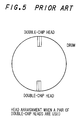
- This SD-VTR is a system corresponding to three head positions and two drum rotating rates, namely, 9000 rpm (cf. Figs. 3 and 4), and 4500 rpm (cf. Fig. 5).
- Fig.6 shows a structure of coding proposed as a provisional standard for the ATV (Advanced Television).
- a symbol I represents a coding process within a frame
- P represents a predictive coding process relative to a forward frame as an interframe coding process
- B represents another predictive coding process relative to both the forward and backward frames.
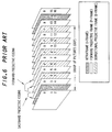
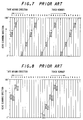
- the video signal thus formulated based on the above interframe predicative coding is recorded as it is on the basis of the SD specifications already consented, the signal is regenerated from several different tracks as disconnected data as shown in Figs.7 and 8 when the system is operated in the picture search playback mode. Accordingly, it is barely possible to reproduce a complete picture with clear content.
- the SD-VTR video signal has a recording capacity of 24.948 Mbps while the ATV bit stream is composed of about 19.3 Mbps, it is possible to record data for special playback into separate areas from those for normal playback data. That is, the remaining part of 5.648 Mbps can be used for the data areas for special playback.
- the tape speed for special playback increases, it becomes necessary to duplicately record the identical data across some or several tracks in consideration of the smoothness of servo lock. That is, as the tape speed increases, the number of duplication increases. Accordingly, the higher the tape speed is, the more increased the amount of invalid data or the less the amount of data to be useful during reproduction becomes.
- the present invention is to provide a digitally recording and reproducing apparatus in which video data for variable-speed playback to be recorded is formed by extracting part of the video data used for variable-speed playback in such a manner that the amount of a reproduced picture at the variable-speed mode is improved from the peripheral part of the reproduced image toward the central part thereof, or in such a manner that the playback picture at the variable-speed mode is improved as the variable-playback speed becomes lower or as the change or movement of the picture becomes slower. That is, the present invention is to reduce the amount of data for variable-speed playback without lowering the visual grade of image quality by improving the quality of image in the important portion in the image where the viewer's attention is drawn upon.
- Gist of the invention resides in that a digitally recording and reproducing apparatus records a desired video signal onto a recording medium by compressing the band range of the desired video signal using a high-efficiency coding technique and has a means for recording part of video data for variable-speed playback onto different recording tracks from those on which video data for normal playback is recorded, and comprises: a means for forming video data for variable-speed playback to be recorded by extracting part of the video data for variable-speed playback in such a manner that the amount of a reproduced picture at the variable-speed mode is improved from the peripheral part of the reproduced image toward the central part thereof.
- the digitally recording and reproducing apparatus having the above configuration further comprises a means which, in a case where the discreet cosine transform is used to compress the band range of the video signal, allots only the d.c. component or part of the d.c. component to data for outermost part of the image frame of a reproduced picture at the variable-speed playback mode and allots a.c. components to data for inner part of the image frame of the reproduced picture, in such a manner that the amount of the a.c.
- the digitally recording and reproducing apparatus having the above configuration further comprises a means which, in a case where the variable-speed playback operation is effected at multiple steps of speed, extracts part of the video data and is adapted to increase the amount of the extracted part as the speed of variable-speed playback decreases, to form the video data for variable-speed playback to be recorded.
- the digitally recording and reproducing apparatus further comprises a means which, in a case where the variable-speed playback operation is effected at multiple steps of speed, forms the video data for variable-speed playback to be recorded, such that part of the video data recorded on the recording medium can be shared between different playback speed modes.
- the digitally recording and reproducing apparatus when part of the video signal whose necessary band range has been compressed is recorded as data for variable-speed playback, the amount of a.c. components (high-frequency components) of data on the outermost part of the frame of a reproduced picture is reduced if the reproduced picture changes fast and the amount of the a.c.
- a first image for variable-speed playback consisting of one frame is displayed for the duration of some or several frames and a second image for variable-speed playback of a next frame is displayed, successibly and repeatedly, in order to display the two frames that are made from each field of one frame, repeatedly in a specified displaying duration and the method of forming two frames from one frame can be selected depending on the position of the image and the moving amount of images, from two schemes: a first of which is that two fields are converted into two frames by converting field data by every DCT block of an image or by every macro block consisting of a plurality of DCT blocks, into frame data; and a second of which is that one frame is converted into two frames by merely repeating the frame by itself.
- the first means is to increase the number of DCT coefficients of data for variable-speed playback stepwise so that the reproduce picture at the variable-speed mode is improved from the peripheral part of the reproduced image toward the central part.
- the second means is to reduce the number of a.c. components recorded, in association with the movement or change of the picture. Specifically, sensitivity of the human's eyes is low to the objects moving sharply and the actual definition of the picture on the monitor declines due to the lowerness of the time response of the camera etc., and due to the influence of residual images on the monitor. Taking advantage of such defective features, the second means reduces the amount of data for variable-speed playback without degrading the quality of the visually observable picture.
- the third means is to reduce the amount of data without degrading the quality of the picture, by rounding off the least significant bits of data in the peripheral part of the image or in the portion where the reproduced picture moves fast. Further, in the case where one frame of variable-speed playback images is repeatedly displayed in the duration of about two-frame equivalent, the picture becomes unnatural if fields containing a time-lag therebetween are alternately displayed. In such a case, it is possible to create a naturally animating picture by creating respective new frames from first and second fields and alternately displaying the thus created two frames.
- a first embodiment of the invention will be explained using ATV bit streams as an example of input signal and a SD-VTR as an example of VTR. It is noted, however, that input signal as well as VTR is not limited to those above.
- the DCT technique is used to compress band widths of video signals.
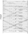
- Fig.9 shows a tape pattern in which patterns each consisting of four tracks are periodically repeated. Each four-track has 37 SBs (containing area a1 in Fig.9 and not containing areas b1 and c1) of data for 4x-speed playback and 48 SBs of 16x-speed playback. The latter is separately distributed in four areas.
- These recording areas are arranged such as to be responsive to the double-azimuth head arrangement or 180° opposing head arrangement, with drum rotational frequencies of 9000 rpm and 4500 rpm.
- Data for 4x-speed playback is duplicately recorded on another track so that the number of head traces on the data may be increased.
- data for 16x-speed playback is duplicately recorded eight times on different tracks. As a result, the pattern of data is repeated in a cycle of 32 tracks. Areas a, b, c with an identical subscript in Fig.9 indicate that those areas have the same data content although recorded in different sites.
- 7 SBs (the area a1 in Fig.9) of the data for 4x-speed playback are also used when the data is reproduced for 16x-speed forward playback by the double azimuth 2-head arrangement with a rotational frequency of 9000 rpm.
- the data in the same recording area can also be used for 16x-speed reverse playback by the double azimuth 2-head arrangement with a rotational frequency of 9000 rpm.
- the aforementioned data of 7SBs are required to duplicately be recorded in other two sites (areas b1 and c2 in Fig.9) within the same four tracks.
- 14 SBs and 7 SBs are the lowest possible data amounts which are estimated to be reproducible during crossing one track in 16x-speed playback mode, in consideration of the interchangeability. Accordingly, if the setup conditions such as the speed of variable-playback and mechanical accuracy and assembling dispersion are changed, the number of SBs of the data should be modified.
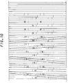
- part of the data for 16x-speed playback may also be used as the data for 4x-speed playback, as shown in Fig.10. It is also possible to create a tape pattern such that part of the data for 16x-speed playback may be used commonly as the data for 4x-speed playback and at the same time, part of the data for 4x-speed playback may also be used as the data for 16x-speed playback.
- Data for 4x-speed playback and data for 16x-speed playback, created from one I-picture are both recorded in a range of 300 tracks.
- Data on the next I-picture is recorded on next 300 tracks.
- data in the area a1 in Fig.9 is repeatedly recorded in areas b1 and c1 in Fig.9. Since contents of data for 4x-speed playback change by every four tracks within 32 tracks, this situation is represented by using subscripts.
- the aforementioned sharing of data cannot be done in 150 tracks where the data for 4x-speed playback and the data for 16x-speed playback represent different image frames or image fields. More specifically, the data is shared in the first 150 tracks within the 300 tracks but is not shared in the second 150 tracks.
- the position of 150 tracks in which the sharing of data is made is not necessarily limited to the first 150 tracks.
- the tape pattern of the invention must be designed by comprehensively examining how big the recording area for data in the variable-speed mode can be ensured; how the image quality in the variable-speed mode is improved as the amount of data readable increases; and how big the unusable part is.
- the present invention is applied to as in the above example, it is possible to utilize many coefficients of a.c. components, especially, for the data in the 16x-speed playback mode, whereby there is a greatest advantage that the image quality in the 16x-speed playback mode is markedly improved.
- Data to be recorded is formulated from I-pictures alone. There can be assumed to be one I-picture in every 10 to 20 frames. Now, explanation will be made on a case where one I-pictures appears in every 15 frames. It is also assumed that there are three frames between I- and P-pictures.
- the total amount of data as to d.c. coefficients for DCT blocks in one I-picture differs depending on the type of image and also depending on the setup condition of the encoder used, the number of data on average is assumed to be about 24 Kbytes, for example.
- a.c. coefficients are recorded in the remaining part.
- the total amount of data as to a.c. coefficients when one a.c. coefficient is allotted to each of DCT blocks in one I-picture differs depending on the type of image and also depending on the setup condition of the encoder used, the number of data on average is assumed to be about 16 Kbytes.
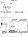
- the a.c. coefficients of chrominance signals are made not to be recorded and the coefficients of the luminance signal Y for pixels from the peripheral part of the screen to one-third of the screen are made not to be recorded. In this condition, two a.c.
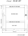
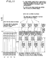
- partitioning of the screen area can be easily done based on the unit of macro blocks (which will be abbreviated hereinbelow as MBs and each consist of 16 x 16 samples, four DCT blocks of the luminance signal Y and two DCT blocks of the chrominance signals), ten MBs on each side of the screen and six MBs on each of upper and lower sides of the screen are determined as a peripheral frame in which only d.c. coefficients of the luminance signal Y and the chrominance signals are to be recorded (Fgi.12).
- the above area may be set up based on the unit of DCT blocks. There is little difference between the case where the area is set up based on MBs and the case where the area is set up based on DCT blocks. In the latter case, the amount of data can be adjusted in a slightly minute manner, but the number of counters increases.
- data for 4x-speed playback it is possible to create the data for 4x-speed playback in the form of the data structure as above. Further, even when recording areas within 32 tracks for the 4x-speed playback data and for the 16x-speed playback data substantially correspond to one another, the amount of data to be read out in the 4x-speed playback mode is about four times as much as that in the 16x-speed playback mode. Hence, it is possible to use more data to reconstruct a variable-speed playback picture. Thus, d.c. coefficients and five kinds of a.c. coefficients are used to construct a 4x-speed playback image.
- the amount of data to be written in a range of four tracks is assumed to be 37 SBs
- the recording area is smaller than the above embodiment, there could occur a case that the image in the peripheral frame portion must be formed of only d.c. coefficients. In such a case, the boundary between the inside and outside parts becomes conspicuous.
- another frame in which the image is composed of d.c. coefficients and two kinds of a.c. coefficients is interposed between the two parts. That is, an image is formed of three regions: the outermost part of only d.c. coefficients; the intermediate part of d.c. coefficients with two kinds of a.c. coefficients; and the central part of d.c. coefficients with five kinds of a.c. coefficients.
- the data structure of the chrominance signals may be composed of two regions: a first region of only d.c. coefficients and a second region of d.c. coefficients and five kinds of a.c. coefficients.
- the data structure of the chrominance signals may be composed in the same configuration as in the luminance signal. Further, partitioning of the areas can be made different from the case of the luminance signal.
- the amount of data as to a certain I-picture may exceed the above-specified data amount above due to the use of the length-variable coding.
- the amount of data is decreased by lowering the quality of image in the peripheral area of the image as stated above while the quality of the visually observable image is inhibited from degrading, thus making it possible to control the amount of data to the specified data amount.
- This operation makes it possible to record the data for variable-speed playback within a range of 300 tracks and therefore allows easy editing.
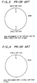
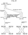
- Figs.13 and 14 show respective methods of constructing data of a field DCT and a frame DCT in the case of the ATV.
- the field-type picture is formed by adaptively selecting field DCT and frame DCT.
- the frame-type picture is formed of field DCT alone because the field data is completely separate.
- an original data in the form of field DCT structure is converted into a new first frame-structure data by replacing data segments Y3 and Y4 in a micro block shown in Fig.14 with data segments Y1 and Y2.
- the original data is converted into a new second frame structure data by replacing data segments Y1 and Y2 in the original micro block with the data segments Y3 and Y4.
- the thus newly formed first and second frames are displayed in this order during only one-frame period. This operation is done on the reproducing side. This procedure is shown in Fig.15 in a simplified manner.
- This procedure makes the displayed picture animate in a natural manner.
- Fig.16 is a block diagram showing a recording side of an embodiment of the invention
- Fig.17 is a block diagram showing a reproducing side of an embodiment of the invention.
- An inputted ATV data stream 211 passes through an interface 221 and then is sent to a rate converter 222 as well as to a packet and packet-header processing circuit 225.
- the rate converter 222 converts the data rate of the inputted data stream so that the converted data may satisfy requirements of the packet processing portions and the data processing rate thereafter.
- the thus converted data stream is sent to a multiplexer 223 where the data stream is multiplexed based on data for variable-speed playback and SB units.
- the thus multiplexed data 213 is supplied to an ECC and digital modulating/recording system 232 in the SD-VCR and recorded on the tape.
- the digital signal decoded as to transport packets and PES packets in the packet and packet-header processing circuit 225 is delivered to an ATV syntax decoding and variable-length code decoding section 226, where the signal is analyzed as to ATV headers and subjected to the variable-length code decoding operation. Then, the thus processed data is delivered to a DCT coefficient selecting circuit 227 and an image position detecting circuit 230.
- This image position detecting circuit 230 detects the image position from the decoded signal of the ATV syntax.
- a control signal generating circuit 231 for controlling the amount of data for variable-speed playback refers to the detected image position and generates a DCT coefficient selecting signal 216 which indicates how many DCT coefficients should be selected.
- the DCT coefficient selecting circuit 227 selects DCT coefficients for all the speeds in the variable-speed playback mode.
- the thus selected DCT coefficients are synchronized in a 6x-speed mode data buffer 228 and a 4x-speed data mode data buffer 229 so as to be multiplexed in the multiplexer 223 with the data for normal playback, as described above.
- the control signal for effecting this multiplexing operation is generated by a track mapping signal generating circuit 224, based on the aforementioned DCT coefficient selecting signal 216, a signal 215 letting a current sync block number represent the amount of data multiplexed and a current track number 214.
- the signal from the SD-VTR reproducing system passes through a digital demodulating/ECC 321 and supplied to a SB data processing circuit 322 which discriminates whether the data supplied is data for normal playback or data for variable-speed playback.
- the data for normal playback is synchronized in a buffer 323 so as to be inputted to a demultiplexer 324 where the inputted data is de-multiplexed.
- a packet reconstructing circuit 325 recreates original packets, which in turn are outputted through a packet interface 326.
- variable-speed playback data processing circuit 327 integrates the data intermittently reproduced and delivers the integrated data to the demultiplexer 324 in synchronism.
- the demultiplexer 324 de-multiplexes only required data, and then the packet reconstructing circuit 325 makes the data length of the demultiplexed data match the length of the ATV packet and adds headers and the like to the data.
- the circuit 325 produces a bit stream in which variable-speed playback image data for one frame are repeated as many as the variable-speed playback image of the frame should be repeatedly displayed. (These procedures are to be repeated to prepare a next frame and thereafter.) The thus produced bit stream is outputted through the packet interface 326.
- Fig.18 is a block diagram showing a recording side of a second embodiment of the invention. The following description will be made on this embodiment.
- the reproducing side of the embodiment can be configurated by the same circuit as in the first embodiment shown in Fig.17.
- the signal After subjected to the ATV syntax decoding operation, the signal is supplied to a movement determining and field DCT discriminating circuit 233, wherein, if some movement in a field DCT block exceeds a prescribed threshold level, a signal indicating the fact is generated to be sent out to the control signal generating circuit 231 for controlling the amount of data for variable-speed playback.
- the circuit 23 based on the signal from the circuit 233, generates a DCT coefficient selecting signal 216 which specifies the number of a.c. coefficients, so that the DCT coefficient selecting circuit 227 selects a.c. coefficients.
- the embodiment shown in Fig.18 operates in the same manner as in the recording side circuit of the embodiment shown in Fig.16, except that the additional operation as follows is added to the configuration of Fig.16.
- reduction of data is effected by selecting DCT coefficients as to a certain part of the video signal, in view of reducing the number of coefficients.
- Fig.19 shows a variational embodiment of the second embodiment, in which, in order to reduce the amount of data, rounding operation of the least significant bits of the data indicating gradations is done as to a certain part of the video signal, in view of reducing the size of each coefficient.
- reduction in the amount of data is effected by discriminating whether the data belongs to the peripheral part of the image frame, whether the data is transformed by the field DCT and how sharply the picture moves.
- a bit-reduction circuit 234 rounds off the data of the video signal at the least or second least significant bit.
- the data should be replaced by a code having the shortest code-length and being closest to the level of the original code. In this operation, if there is no code having a shorter code-length, the level need not be changed. Since these operations can be formulated by a rule determined in advance and the transformation can be carried out based on the rule using ROMs, RAMs and the like, the size of the circuit and the processing time increase very little.
- the first, second and third embodiments it is possible to reduce the amount of data while the quality of the image in important part of the picture is maintained.
- an a.c. coefficient for one frame of an I-picture is assumed to have 16 bytes, the amount of data might increase if a picture of high-quality is inputted. Even if such a case occurs, it is possible to deal with the case, by combining the methods of the first, second and third embodiments.
- VTR system in which, in recording a video signal, the signal is used to generate data for variable-speed playback to be stored in areas from which the data can be read out in the variable-speed playback mode and at the time of reproducing in the variable-speed playback mode, the less data than in the usual playback mode is quickly read out.
- the configuration of reproducing operation at a variable speed can be applied similarly to any system in which recording areas of readable data is not limited while data-readout takes a longer time than data-decoding.
- any of the methods shown in the embodiments of the invention or their combination can be effected by only the operation at the time of reading out. Thereby, it is possible to watch briefed content of a picture recorded, in order to seize an outline of the picture in a short period of time.
- the ATV bit stream is stored in a large-capacity semiconductor memory, it is possible to save the time required for decode the data by reading out data on the central part of the picture by every slicing unit. If data on the areas in the upper and lower ten MBs is not read out, the data to be processed becomes reduced to 1/1.4. At this moment, data on the peripheral area is set at the pedestal level. Further, if only I- and P-pictures are adapted to be decoded for playback, the amount of data to be processed is reduced to about one-third. Accordingly, the whole content can be checked in about 1/4.2 of the original time. Moreover, when only I-pictures are used, the amount of data is further reduced to 1/5, that is, the whole content can be briefly checked in about 1/20 of the original time.
- Decoding of variable length codes is basically done by effecting pattern matching operations by every bit unit. Therefore, this operation requires many loops, taking more time than the other processing. Accordingly, if, in decoding the variable length codes, variable length codes with only a d.c. coefficient and two a.c. coefficients are taken to be subjected to the decoding operation, a further reduction of the processing time can be made. For instance, an animation of 2 hours at the normal speed can be watched in about five minutes.
- this method is useful when the user wants to roughly grasp the content of video data recorded, although there is no need for searching a head or start of content as needed in the VTR system.
- the present invention relates a recording apparatus for recording television signals having a wide band-range for the ATV, HDTV or the like which, in recent years, attracts a good deal of public attention as a near-future television apparatus of high quality of image with a wide display. That is, the present invention relates to a digital VTR which is able to record a band-compressed signal having a bit-rate of 17 to 60 Mbps of a program while creating a low-bit-rate signal (1.5 to 5 Mbps) having the same program content as well as utilizing the low-bit-rate signal as a signal for the special playback.
- the present invention proposes a first method that variable-speed playback data for a certain speed, which is recorded in the limited recording areas for variable-speed playback mode, is adapted to be used for playback at another speed in the variable-speed playback mode. Further, the invention proposes a second method that data structure of variable-speed playback data is adapted to change depending on the image areas on the image frame. Either of the above methods or the combination of them is able to improve the quality of picture at the variable-speed playback mode in which a less amount of data is available than that of data read out at the time of the normal playback mode.
Landscapes
- Engineering & Computer Science (AREA)
- Signal Processing (AREA)
- Multimedia (AREA)
- Television Signal Processing For Recording (AREA)
- Signal Processing For Digital Recording And Reproducing (AREA)
Applications Claiming Priority (2)
| Application Number | Priority Date | Filing Date | Title |
|---|---|---|---|
| JP279389/94 | 1994-11-14 | ||
| JP27938994A JP3172643B2 (ja) | 1994-11-14 | 1994-11-14 | ディジタル記録再生装置 |
Publications (2)
| Publication Number | Publication Date |
|---|---|
| EP0712254A2 true EP0712254A2 (de) | 1996-05-15 |
| EP0712254A3 EP0712254A3 (de) | 1997-03-26 |
Family
ID=17610454
Family Applications (1)
| Application Number | Title | Priority Date | Filing Date |
|---|---|---|---|
| EP95117721A Withdrawn EP0712254A3 (de) | 1994-11-14 | 1995-11-09 | Digitale Aufnahme- und Wiedergabeanlage |
Country Status (5)
| Country | Link |
|---|---|
| US (1) | US5692092A (de) |
| EP (1) | EP0712254A3 (de) |
| JP (1) | JP3172643B2 (de) |
| KR (1) | KR100222219B1 (de) |
| CN (1) | CN1138413C (de) |
Families Citing this family (10)
| Publication number | Priority date | Publication date | Assignee | Title |
|---|---|---|---|---|
| JP3575100B2 (ja) * | 1994-11-14 | 2004-10-06 | ソニー株式会社 | データ送信/受信装置及び方法並びにデータ記録/再生装置及び方法 |
| KR0165439B1 (ko) * | 1995-09-14 | 1999-03-20 | 김광호 | 디지탈 비디오 테이프 레코더의 화면 구성 장치 및 방법 |
| US6292621B1 (en) * | 1996-02-05 | 2001-09-18 | Canon Kabushiki Kaisha | Recording apparatus for newly recording a second encoded data train on a recording medium on which an encoded data train is recorded |
| US6012091A (en) * | 1997-06-30 | 2000-01-04 | At&T Corporation | Video telecommunications server and method of providing video fast forward and reverse |
| US6389218B2 (en) * | 1998-11-30 | 2002-05-14 | Diva Systems Corporation | Method and apparatus for simultaneously producing compressed play and trick play bitstreams from a video frame sequence |
| KR100346689B1 (ko) * | 1998-12-15 | 2002-10-19 | 삼성전자 주식회사 | 가변속재생방법및그장치 |
| US6593936B1 (en) * | 1999-02-01 | 2003-07-15 | At&T Corp. | Synthetic audiovisual description scheme, method and system for MPEG-7 |
| KR100403238B1 (ko) * | 2000-09-30 | 2003-10-30 | 엘지전자 주식회사 | 비디오의 지능형 빨리 보기 시스템 |
| CN101661766B (zh) * | 2003-11-12 | 2011-07-27 | 松下电器产业株式会社 | 记录介质、再现装置和方法、记录方法以及计算机可读取程序 |
| JP4448714B2 (ja) * | 2004-03-03 | 2010-04-14 | パイオニア株式会社 | デジタル画像信号復号化装置及び復号化方法 |
Family Cites Families (13)
| Publication number | Priority date | Publication date | Assignee | Title |
|---|---|---|---|---|
| JPH03129987A (ja) * | 1989-10-14 | 1991-06-03 | Sony Corp | 映像信号符号化装置及び映像信号符号化方法 |
| JPH03143086A (ja) * | 1989-10-27 | 1991-06-18 | Sony Corp | 復号装置 |
| US5103306A (en) * | 1990-03-28 | 1992-04-07 | Transitions Research Corporation | Digital image compression employing a resolution gradient |
| KR970007530B1 (ko) * | 1991-09-30 | 1997-05-10 | 가부시기가이샤 도시바 | 대역 압축 신호 처리 장치 |
| US5414469A (en) * | 1991-10-31 | 1995-05-09 | International Business Machines Corporation | Motion video compression system with multiresolution features |
| GB2264020B (en) * | 1992-01-31 | 1995-10-25 | Sony Broadcast & Communication | Digital video signal processing |
| US5440345A (en) * | 1992-07-17 | 1995-08-08 | Kabushiki Kaisha Toshiba | High efficient encoding/decoding system |
| JP3184011B2 (ja) * | 1992-07-20 | 2001-07-09 | 株式会社東芝 | 帯域圧縮信号処理装置 |
| US5392223A (en) * | 1992-07-29 | 1995-02-21 | International Business Machines Corp. | Audio/video communications processor |
| US5583650A (en) * | 1992-09-01 | 1996-12-10 | Hitachi America, Ltd. | Digital recording and playback device error correction methods and apparatus for use with trick play data |
| US5402146A (en) * | 1992-10-23 | 1995-03-28 | International Business Machines Corporation | System and method for video compression with artifact dispersion control |
| US5377051A (en) * | 1993-01-13 | 1994-12-27 | Hitachi America, Ltd. | Digital video recorder compatible receiver with trick play image enhancement |
| JP3261844B2 (ja) * | 1993-01-13 | 2002-03-04 | 株式会社日立製作所 | デジタルビデオ記録装置及び記録方法 |
-
1994
- 1994-11-14 JP JP27938994A patent/JP3172643B2/ja not_active Expired - Fee Related
-
1995
- 1995-11-09 EP EP95117721A patent/EP0712254A3/de not_active Withdrawn
- 1995-11-14 CN CNB951215922A patent/CN1138413C/zh not_active Expired - Fee Related
- 1995-11-14 KR KR1019950041242A patent/KR100222219B1/ko not_active Expired - Fee Related
- 1995-11-14 US US08/557,498 patent/US5692092A/en not_active Expired - Lifetime
Non-Patent Citations (2)
| Title |
|---|
| BOYCE ET AL: "Fast Scan Technology for Digital Video Tape Recorders", IEEE TRANSACTIONS ON CONSUMER ELECTRONICS, vol. 39, no. 3, August 1993 (1993-08-01), NEW-YORK, USA, pages 186 - 191 * |
| KOGURE ET AL: "Matsushita Proposal Description for MPEG-II", 1 November 1991, INTERNATIONAL ORGANIZATION FOR STANDARDISATION, GENEVA, CH * |
Also Published As
| Publication number | Publication date |
|---|---|
| JP3172643B2 (ja) | 2001-06-04 |
| KR960019247A (ko) | 1996-06-17 |
| EP0712254A3 (de) | 1997-03-26 |
| CN1144435A (zh) | 1997-03-05 |
| JPH08140048A (ja) | 1996-05-31 |
| CN1138413C (zh) | 2004-02-11 |
| US5692092A (en) | 1997-11-25 |
| KR100222219B1 (ko) | 1999-10-01 |
Similar Documents
| Publication | Publication Date | Title |
|---|---|---|
| EP0683611B1 (de) | Numerische Aufnahme- und Wiedergabevorrichtung | |
| US6018611A (en) | Recording apparatus which adaptively records amounts of low resolution video inversely to amounts of high resolution video which has the same program content | |
| EP0613297B1 (de) | Digitaler Videorecorder für hochauflösende Fernsehsignale mit Betriebsarten für spezielle Wiedergabe | |
| RU2191469C2 (ru) | Видеопередающее устройство, использующее внутрикадровую видеокомпрессию, совместимую со стандартом мпег-2 | |
| JPH04298802A (ja) | 高能率符号化記録再生装置 | |
| CN1122987A (zh) | 记录数字视频信号的方法和设备及再现数字视频信号设备 | |
| JP3277713B2 (ja) | ディジタルビデオ信号の記録装置、記録再生装置及び再生装置 | |
| JP3921841B2 (ja) | 信号処理装置および方法、ならびに、記録装置、再生装置および記録再生装置 | |
| US5692092A (en) | Recording and playback system for variable speed playback wherein more a.c. coefficients are allotted to the macroblocks in the central part of an image frame | |
| JP2000138897A (ja) | データ処理装置およびデータ記録装置 | |
| US6807366B1 (en) | Data recording apparatus, data recording/reproducing apparatus, data recording method, and data recording/reproducing method | |
| CN101835055A (zh) | 数字视频信号的记录和重放设备及其记录和重放的方法 | |
| JP3034172B2 (ja) | 画像データ記録再生装置 | |
| CN1925625B (zh) | 数字视频信号的记录和重放设备及其记录和重放的方法 | |
| JP2004120799A (ja) | ディジタルデータ伝送装置及びその伝送方法 | |
| JP3231833B2 (ja) | 帯域圧縮信号処理装置 | |
| JP2000132914A (ja) | データ処理装置およびデータ記録装置 | |
| JP4069823B2 (ja) | 特殊再生用データ作成装置 | |
| JP3572659B2 (ja) | ディジタルビデオ信号の記録装置、再生装置、記録再生装置及び記録媒体 | |
| JP3978903B2 (ja) | データ記録装置、データ記録方法、データ処理装置、およびデータ処理方法 | |
| JPH0898140A (ja) | ディジタル信号再生装置および記録再生装置 | |
| JP3284678B2 (ja) | ディジタルビデオ信号記録方法及び記録装置 | |
| JP3257243B2 (ja) | ディジタルビデオ信号の記録方法及び記録装置 | |
| JP2000152174A (ja) | 画像データ処理装置および方法、並びに画像データ記録装置 | |
| JPH0923406A (ja) | ディジタル記録再生装置 |
Legal Events
| Date | Code | Title | Description |
|---|---|---|---|
| PUAI | Public reference made under article 153(3) epc to a published international application that has entered the european phase |
Free format text: ORIGINAL CODE: 0009012 |
|
| AK | Designated contracting states |
Kind code of ref document: A2 Designated state(s): DE ES FR GB |
|
| RIN1 | Information on inventor provided before grant (corrected) |
Inventor name: AKIMOTO, SAORI Inventor name: AOKI, KAZUYA Inventor name: SHIRAISHI, KENICHI Inventor name: KAWAGUCHI, KOICHI Inventor name: KATAYAMA, HIRONOBU Inventor name: NOGAMI, HIROAKI |
|
| PUAL | Search report despatched |
Free format text: ORIGINAL CODE: 0009013 |
|
| AK | Designated contracting states |
Kind code of ref document: A3 Designated state(s): DE ES FR GB |
|
| 17P | Request for examination filed |
Effective date: 19970604 |
|
| 17Q | First examination report despatched |
Effective date: 19970828 |
|
| STAA | Information on the status of an ep patent application or granted ep patent |
Free format text: STATUS: THE APPLICATION IS DEEMED TO BE WITHDRAWN |
|
| 18D | Application deemed to be withdrawn |
Effective date: 20051228 |