EP0712042A2 - System zur Lieferung von Filmeinheiten, Behälter für Filmeinheiten und Apparat zur Verpackung von Abfall für die Wiederverwertung - Google Patents
System zur Lieferung von Filmeinheiten, Behälter für Filmeinheiten und Apparat zur Verpackung von Abfall für die Wiederverwertung Download PDFInfo
- Publication number
- EP0712042A2 EP0712042A2 EP95306763A EP95306763A EP0712042A2 EP 0712042 A2 EP0712042 A2 EP 0712042A2 EP 95306763 A EP95306763 A EP 95306763A EP 95306763 A EP95306763 A EP 95306763A EP 0712042 A2 EP0712042 A2 EP 0712042A2
- Authority
- EP
- European Patent Office
- Prior art keywords
- sheet
- negative
- ram
- sheets
- positive
- Prior art date
- Legal status (The legal status is an assumption and is not a legal conclusion. Google has not performed a legal analysis and makes no representation as to the accuracy of the status listed.)
- Withdrawn
Links
- 238000004064 recycling Methods 0.000 title claims abstract description 7
- 239000010816 packaging waste Substances 0.000 title 1
- 239000010813 municipal solid waste Substances 0.000 claims abstract description 56
- 239000007788 liquid Substances 0.000 claims abstract description 47
- 230000007480 spreading Effects 0.000 claims abstract description 12
- 238000003892 spreading Methods 0.000 claims abstract description 12
- 239000000463 material Substances 0.000 claims abstract description 8
- 238000012545 processing Methods 0.000 claims description 27
- 238000000034 method Methods 0.000 claims description 22
- 230000008569 process Effects 0.000 claims description 19
- 238000007789 sealing Methods 0.000 claims description 8
- 238000000151 deposition Methods 0.000 claims description 6
- 230000007246 mechanism Effects 0.000 claims description 6
- 238000012856 packing Methods 0.000 claims description 6
- 230000013011 mating Effects 0.000 claims description 5
- 239000012528 membrane Substances 0.000 claims description 5
- 239000012530 fluid Substances 0.000 claims description 4
- 230000001154 acute effect Effects 0.000 claims description 2
- 230000035515 penetration Effects 0.000 claims description 2
- 238000005213 imbibition Methods 0.000 abstract description 8
- 238000012546 transfer Methods 0.000 description 9
- 238000009792 diffusion process Methods 0.000 description 5
- 239000011888 foil Substances 0.000 description 5
- 230000008901 benefit Effects 0.000 description 3
- 239000000428 dust Substances 0.000 description 3
- 239000000853 adhesive Substances 0.000 description 2
- 230000001070 adhesive effect Effects 0.000 description 2
- 238000010586 diagram Methods 0.000 description 2
- 238000001035 drying Methods 0.000 description 2
- 238000003780 insertion Methods 0.000 description 2
- 230000037431 insertion Effects 0.000 description 2
- 230000002093 peripheral effect Effects 0.000 description 2
- 239000002699 waste material Substances 0.000 description 2
- 230000009471 action Effects 0.000 description 1
- 238000013459 approach Methods 0.000 description 1
- 230000008859 change Effects 0.000 description 1
- 238000013461 design Methods 0.000 description 1
- 238000005516 engineering process Methods 0.000 description 1
- 238000004806 packaging method and process Methods 0.000 description 1
- 238000003825 pressing Methods 0.000 description 1
- 230000003014 reinforcing effect Effects 0.000 description 1
- 239000011347 resin Substances 0.000 description 1
- 229920005989 resin Polymers 0.000 description 1
- 230000000717 retained effect Effects 0.000 description 1
- 238000000926 separation method Methods 0.000 description 1
- 238000005728 strengthening Methods 0.000 description 1
- 230000007704 transition Effects 0.000 description 1
Images


Classifications
-
- B—PERFORMING OPERATIONS; TRANSPORTING
- B65—CONVEYING; PACKING; STORING; HANDLING THIN OR FILAMENTARY MATERIAL
- B65F—GATHERING OR REMOVAL OF DOMESTIC OR LIKE REFUSE
- B65F1/00—Refuse receptacles; Accessories therefor
- B65F1/14—Other constructional features; Accessories
- B65F1/16—Lids or covers
- B65F1/1607—Lids or covers with filling openings
-
- B—PERFORMING OPERATIONS; TRANSPORTING
- B65—CONVEYING; PACKING; STORING; HANDLING THIN OR FILAMENTARY MATERIAL
- B65D—CONTAINERS FOR STORAGE OR TRANSPORT OF ARTICLES OR MATERIALS, e.g. BAGS, BARRELS, BOTTLES, BOXES, CANS, CARTONS, CRATES, DRUMS, JARS, TANKS, HOPPERS, FORWARDING CONTAINERS; ACCESSORIES, CLOSURES, OR FITTINGS THEREFOR; PACKAGING ELEMENTS; PACKAGES
- B65D43/00—Lids or covers for rigid or semi-rigid containers
- B65D43/14—Non-removable lids or covers
- B65D43/16—Non-removable lids or covers hinged for upward or downward movement
- B65D43/162—Non-removable lids or covers hinged for upward or downward movement the container, the lid and the hinge being made of one piece
-
- B—PERFORMING OPERATIONS; TRANSPORTING
- B65—CONVEYING; PACKING; STORING; HANDLING THIN OR FILAMENTARY MATERIAL
- B65F—GATHERING OR REMOVAL OF DOMESTIC OR LIKE REFUSE
- B65F1/00—Refuse receptacles; Accessories therefor
- B65F1/14—Other constructional features; Accessories
- B65F1/1405—Compressing means incorporated in, or specially adapted for, refuse receptacles
-
- G—PHYSICS
- G03—PHOTOGRAPHY; CINEMATOGRAPHY; ANALOGOUS TECHNIQUES USING WAVES OTHER THAN OPTICAL WAVES; ELECTROGRAPHY; HOLOGRAPHY
- G03B—APPARATUS OR ARRANGEMENTS FOR TAKING PHOTOGRAPHS OR FOR PROJECTING OR VIEWING THEM; APPARATUS OR ARRANGEMENTS EMPLOYING ANALOGOUS TECHNIQUES USING WAVES OTHER THAN OPTICAL WAVES; ACCESSORIES THEREFOR
- G03B17/00—Details of cameras or camera bodies; Accessories therefor
- G03B17/48—Details of cameras or camera bodies; Accessories therefor adapted for combination with other photographic or optical apparatus
- G03B17/50—Details of cameras or camera bodies; Accessories therefor adapted for combination with other photographic or optical apparatus with both developing and finishing apparatus
- G03B17/52—Details of cameras or camera bodies; Accessories therefor adapted for combination with other photographic or optical apparatus with both developing and finishing apparatus of the Land type
-
- G—PHYSICS
- G03—PHOTOGRAPHY; CINEMATOGRAPHY; ANALOGOUS TECHNIQUES USING WAVES OTHER THAN OPTICAL WAVES; ELECTROGRAPHY; HOLOGRAPHY
- G03D—APPARATUS FOR PROCESSING EXPOSED PHOTOGRAPHIC MATERIALS; ACCESSORIES THEREFOR
- G03D9/00—Diffusion development apparatus
- G03D9/02—Diffusion development apparatus using rupturable ampoules of liquid
-
- B—PERFORMING OPERATIONS; TRANSPORTING
- B65—CONVEYING; PACKING; STORING; HANDLING THIN OR FILAMENTARY MATERIAL
- B65D—CONTAINERS FOR STORAGE OR TRANSPORT OF ARTICLES OR MATERIALS, e.g. BAGS, BARRELS, BOTTLES, BOXES, CANS, CARTONS, CRATES, DRUMS, JARS, TANKS, HOPPERS, FORWARDING CONTAINERS; ACCESSORIES, CLOSURES, OR FITTINGS THEREFOR; PACKAGING ELEMENTS; PACKAGES
- B65D2209/00—Provisions for used articles
Definitions
- This invention relates to a system which is environmentally friendly while processing self-developing photographic film, in that, it uses materials which are largely reusable and recyclable.
- the system of this invention collects the trash and other residue from the developing process and deposits it in a container for transportation to a recycling center.
- Each film unit comprises a negative or photosensitive film sheet for forming a negative image of a subject, an image receiving film sheet for forming a positive subject image thereof and a rupturable pod of processing liquid.
- a positive image is formed on the positive sheet by means of a well known diffusion transfer process after the pod containing the processing liquid is ruptured and its contents spread between the positive and negative film sheets.
- Film units of the aforementioned type are typically exposed in portable, multiple-exposure, instant-type photographic cameras or processed in large format film processing equipment.
- When employed in a camera as many as ten film units are provided in a single lightweight film pack, in a stacked relation, with the positive sheet on one side and the negative sheet on the other side of a pressure plate located within she film pack.
- Pull tabs are attached to one or both of the leading ends of the positive and negative sheets. After exposing an outer-most negative sheet at a film plane of the camera, a first tab attached to the negative sheet is withdrawn from the camera forcing the exposed negative to be turned 180° about the pressure plate and into superposition with the positive sheet.
- This movement causes a second tab attached to the forward ends of the positive and negative sheets to enter the bite of a pair of pressure applying spread rollers.
- a combination of the angle at which the first tab is attached and the force applied by a camera operator causes the first tab to detach from the negative sheet at this time.
- the operator pulls the second tab so as to advance the positive and negative sheets between the pair of spread rollers in a superposed relation.
- the spread rollers apply pressure to a pod containing a processing liquid located at the leading ends thereof, thereby rupturing same, and spreading its contents between the superposed sheets in a thin uniform layer as the sheets are advanced therebetween.
- a positive image is formed on the positive sheet outside of the camera by a well known diffusion transfer process. After a required interval of time the positive image is manually peeled away from its associated negative and the negative, along with the second tab attached thereto, are discarded.
- a more detailed description of this particular type of peel-apart film may be found at pages 185-187 of a book entitled, "Camera Technology' by Norman Goldberg published in 1992 by the Academic Press.
- the above-described peel-apart film format has several disadvantages, especially if considered for use in certain photographic apparatus.
- One disadvantage is film cost.
- economies of scale are limited by the fact that both a positive and a negative sheet must be included within a single film cassette. Including significantly larger numbers of film units within a single cassette in order to take advantage of such economies would substantially increase cassette size and thereby make such a cassette unwieldy for use by a camera operator.
- Another disadvantage is that this type of film format is not susceptible of inclusion in highly automated film processing equipment. Processing a film unit by pulling certain tabs at various times in the film processing cycle is clearly a processing technique that is inherently manual.
- Another disadvantage of this system is the environmentally unfriendly result of disposal of trash from the film developing process where the negative film sheet, empty pod and spent developer liquid are stripped from the positive and deposited in conventional trash containers on the street.
- a process for developing film and disposing of the residue comprises the steps of: mating a positive film sheet with an exposed negative film sheet; spreading a layer of processing liquid between said sheets, peeling said negative film sheet and any residual portion of said liquid from said positive film sheet, after allowing a suitable period of time for said processing liquid to work; pushing said peeled negative film sheet and residual liquid into a trash container; and sealing said container for shipment to a recycling and disposal location.
- a trash container comprises: a rear wall joined to four sidewalls, said sidewalls diverging from each other at an acute angle and terminating in a planer shoulder which is remote from and parallel with said rear wall; a lid movably secured to said shoulder, said lid combining with said rear wall and sidewalls to form an enclosure, said lid including an opening therethrough for receiving trash, said opening including stripper tabs at its edge; and one said sidewall including an outwardly projecting offset, said offset providing a passage extending from said shoulder to said rear wall.
- a container and its contents comprising: said container including a rear wall, a plurality of sidewalls connected to and extending from said rear wall, and a lid covering said sidewalls to form an enclosure; said lid including an opening to receive trash inserted into said enclosure; a collection of trash within said enclosure, said trash comprising a plurality of layers of negative film sheets and a residue to processing liquid sandwiched together to form a block; and a sealing membrane extending across said opening and clamped in fluid tight engagement between said lid and said sidewalls.
- apparatus for collecting trash comprises: a divider for separating a positive film sheet from a negative film sheet in a photographic film developing apparatus and depositing the separated negative sheet on a reciprocating ram; a clamp for holding said separated negative sheet on said reciprocating ram; said ram being configured to reciprocate into and out of a trash container; said container including a closed lid with an opening therein, said opening being configured to receive said ram and said separated negative sheet; and said ram and container including a release for said clamp upon said ram passing through said lid opening of said container.
- an environmentally friendly handling system for transporting, processing and disposing of photographic materials comprises the steps of: assembling a cassette of negative film sheets with a cassette of positive film sheets, said positive film sheets having attached pods of processing liquid at one end, and inserting both cassettes into a tray and sealing said tray; breaking said seal and removing said cassettes; mounting said cassette of negative film sheets into a camera, exposing said negative film sheets and transferring said exposed sheets to a film processor; mounting said cassette of positive film sheets on said film processor; mounting said tray or one of similar configuration on said film processor; mating an exposed negative sheet with a positive sheet, rupturing said pod and spreading its liquid contents between said sheets, thereby forming a visible image on said positive sheet; separating said positive sheet from said negative sheet; and depositing said separated negative sheet into said tray.
- apparatus for separating positive and negative film sheets after processing liquid has been spread between them in a liquid spreading area comprises: said positive and negative sheets being mated in juxtaposed position, each sheet including a leading end and a trailing end, the leading end of said positive sheet including an evacuated pod which previously held said processing liquid; said leading end of said positive sheet being secured to said leading end of said negative sheet; a first path in said apparatus defining movement of said mated sheets from said liquid spreading area to a peeler, said peeler comprising a pick mounted to reciprocate in a second path transverse to said first path, said pick being located on the positive sheet side of said mated sheets as said mated sheets move in said first path to a first triggering mechanism; and said pick being actuated by said first triggering mechanism to move along said second path to mechanically engage said leading end of said positive sheet and peel said negative sheet and pod from said positive sheet.
- a trash packing apparatus comprises: a plate having a front side and a rear side, said front side serving to engage trash to be rammed into a container; said plate being pivotally mounted on a bar, said bar being connected to said rear side and at a location intermediate first and second ends of said plate; said bar being connected to a pivotable arm, said arm being pivotable in an arc which is perpendicular to said front side of said plate; and said first end of said plate including a clamp to press said trash against said front side, and a clamp release movable with said plate actuated by penetration of said front end of said plate into said container to release said trash from said plate.
- This invention intends to solve several of the aforementioned problems by providing a packaging system wherein the film sheets which are exposed, removed from a film cassette and developed to provide a visible image on the positive film sheet are a part of a trash collection and recycling system.
- the negative film sheet, evacuated pod for developer liquid and any residual developer liquid remaining are stripped from the positive sheet and deposited in the same container in which the film sheets were originally delivered.
- the container is then resealed and delivered to a recycling center where the trash materials may be processed, recycled or simply reused.
- a three compartment carton for transporting four containers or trays of film units is involved.
- film transport trays are deposited in the center section of the carton as it is received by a customer.
- Each of the film trays is hermetically sealed to prevent dust and excess moisture from contaminating film sheets within a pair of cassettes in each such tray.
- Each tray includes a- cassette having positive film sheets and each positive film sheet includes a pod of developer liquid secured to its leading end.
- Each tray also includes a second cassette having a plurality of negative film sheets enclosed therein. Because the tray is hermetically sealed, neither cassette requires such sealing.
- the cassette of positive film sheets is removed from the tray and inserted into a film developing apparatus.
- the cassette of negative film sheets is inserted into a camera where each sheet is exposed in sequence, as desired.
- a lightight transfer cassette encloses the negative cassette and the negative film sheet exposed by the camera which is subsequently deposited in the same film developing apparatus as the cassette of positive film sheets, by a camera operator.
- the empty tray, which previously contained the positive and negative film cassettes, is mounted on the same film developing apparatus. Sheets from both the positive cassette and the transfer cassette are extracted by the film developing apparatus and mated to each other, one at a time, in sequence. The mated sheets pass through a pair of spread rollers to rupture the developer liquid pod and spread its contents between the film sheets. The mated pair of film sheets is next delivered along a first path into an imbibition chamber for a period of time sufficient to complete the diffusion transfer process. Thereafter, the mated sheets continue along the first path and as they exit the imbibition chamber a pick, traveling in a second path, engages the leading end of the mated sheets for the purpose of stripping the pod, negative sheet and residual developer liquid from the positive sheet.
- the positive sheet goes one way and the pick takes the negative sheet another way to deposit it on the face of a movable plate.
- the stripped negative sheet is clamped to the movable plate which is then pushed through an opening in the lid of the empty tray which originally delivered the cassettes to the customer.
- the positive cassette is removed from the developing apparatus and manually deposited in the film tray which has been removed from the developing apparatus and which is only partially filled with stripped negative sheets.
- the four trays containing the stripped negative sheets and positive cassette are re-sealed and placed in the original carton which delivered them.
- the empty negative cassettes from the camera are deposited in the two side compartments which were empty when the carton arrived.
- the carton is then shipped to a recycling or disposal center for further processing.
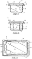
- Figs. 1-6 illustrate a container or tray 10 which is involved in essentially all of the procedural aspects of the invention to be described herein.
- the tray 10 is formed of a clear resin material and having a bottom wall 12 formed integral with upward projecting side walls 14 and 16 and end walls 18 and 20.
- side walls 14 and 16 and end walls 18 and 20 diverge upwardly from bottom wall 12 to terminate in an inverted U-shaped ridge 22 which extends peripherally around the tray formed by the side walls and end walls.
- a flange 24 projects radially from the lower end of the U-shaped ridge approximately parallel with bottom wall 12.
- a lid 26 is formed integrally as a part of the tray 10 and is hingedly connected at 28 to flange 24 radially outward of the end wall 20.
- the upper surface 30 of lid 26 is preferably planar and is disposed generally parallel with bottom wall 12 when in a closed position.
- a reinforcing ridge 32 projects upwardly from planar surface 30 and extends peripherally around a uniquely shaped opening 34; the function of opening 34 will be explained subsequently in relation to Figs. 11-15.
- Ridge 32 serves to reinforce and strengthen the edge surfaces of opening 34 as well as the lid 26 generally.
- Offsets 36 of the ridge 32 near one end of the lid 26 serve as insertion limiting stops for when the tray 10 is inserted into a film processing unit. Tray 10 is inserted into a film processing unit for purposes of receiving negative sheets which must be disposed of as trash and which may be inserted through the opening 34.
- the offsets 36 allow flange 24 and closed lid 26 to slide into slots in the developing apparatus until the edges of the slot engage the offsets 36. This provides an alignment mechanism for the tray in general.
- the outermost leg 38 of U-shaped ridge 22 is inclined inwardly toward end wall 18. This is true of the full length of the outer leg 38 such that the leg extending peripherally around the tray provides an undercut 40 such that a matingly configured leg 42 extending from peripherally around the tray from lid 26 toward the flange 24 snaps or hooks into undercut 40 to hold the lid in locked closed position.
- a strengthening flange 44 projects radially outward from the lower end of leg 42 generally parallel with flange 24.
- Figs. 1-6 illustrate tray 10 as being empty while Fig. 7 shows a fluid impermeable membrane or foil sheet 46 extending across the tray to hermetically secure its contents.
- a layer of suitable adhesive is spread between foil sheet 46 and ridge surface 48 at the top of ridge 22.
- the peripheral edge of sheet 46 is deflected down to be trapped between outermost leg 38 of ridge 22 and mating leg 42 on lid 26.
- the thickness of foil sheet 46 is exaggerated in Fig. 7 for purposes of illustration but the adhesive on surface 48 and the clamping or locking action of leg 42 provides a double seal for foil sheet 46. This double seal minimizes the possibility of dust and moisture reaching the contents of tray 10 when it is being transported from one location to another.
- the flat or planar surface 30 of lid 26 is vertically spaced from sheet 46 as illustrated in Fig. 7. Inherently it is also spaced from ridge surface 48 when foil sheet 46 has been stripped from the tray 10 and the lid 26 is replaced thereon.
- end wall 20 of tray 10 is the offset section 50 which forms a passageway 52 within the interior of tray 10.
- the passageway 52 serves to accommodate a clamp used in depositing waste material in tray 10 which will be explained in detail below in relation to the film developing and trash disposal process and apparatus.
- Fig. 6 illustrates a depression 54 in bottom wall 12 and it will be noted that it is of a particular generally rectangular shape and it serves two purposes.
- the depression 54 strengthens the structure of bottom wall 12 and in addition it serves as the engaging surface for trash inserted through opening 34 while leaving a peripheral trough or depression around surface 54 to accommodate excess liquid which may accompany trash inserted into tray 10 and pressed against the inside surface of depression 54.
- tray 10 is designed to receive a pair of cassettes 56, 58 before peel sheet 46 is applied to hermetically seal the contents against moisture and dust as illustrated in Fig. 7 and before lid 26 is snapped into place.
- the benefit is that the two cassettes 56, 58 do not have to be separately hermetically sealed when transported to a user.
- cassette 56 is shown to be larger than cassette 58. This is intentional.
- Cassette 58 is intended to be filled with a plurality of negative film sheets. Because of their structure, negative film sheets occupy a smaller volume of space than the cassette 56 which is intended to contain a similar number of positive film sheets.
- Each positive film sheet incorporates a pod of developer liquid on its leading end and possibly an excess liquid trap on its trailing end. It is because of the pod of developer liquid that the cassette 56 containing the positive film sheets requires a greater volume to house the same number of sheets as are contained in negative film cassette 58.
- FIG. 8 While it is not required, it is preferred that four full film trays 10 be placed in a box or carton 60 having three separate compartments as illustrated in Fig. 8.
- Carton 60 shown in open empty condition in Fig. 8 receives the four trays 10 in the central compartment while the side compartments remain empty when the carton is delivered to a user.
- the side compartments have a use which will be described in relation to Fig. 17 when the carton and four trays of developer trash is assembled and forwarded to a disposal and recycling center.
- the preferred procedure for a user of the apparatus is for the peel strip 46 to be stripped from tray 10 and the cassettes 56 and 58 removed therefrom as illustrated in Fig. 9.
- Cassette 58 is inserted into a camera (not shown) within a transfer cassette 62 where a negative film sheet enclosed therein is exposed.
- transfer cassette 62 is inserted into a film processing apparatus illustrated schematically in Fig. 10.
- Cassette 56 containing the positive film sheets, pods of developer liquid and trailing liquid trap is inserted, in operative position, into the developer apparatus. Thereafter, one sheet from each of cassettes 56, 62 is extracted and mated by appropriate means so that the exposed portion of the negative sheet from cassette 62 is in registration with an appropriate section of a positive film sheet from cassette 56.
- the mated sheets with the pod of developer liquid on the leading end progresses along a first path 64 to a pair of rollers 66 which pull the mated film sheets through the bite of the rollers, rupture the pod of developer liquid and spread the liquid contents between the two sheets to thereby cause a visible image to be formed on the positive film sheet from the exposed negative film sheet, by a well known diffusion transfer process.
- Film sheets are ejected from the bite of rollers 66 and continue along first path 64 to an imbibition chamber 68 which is heated by a heater 70. After a short pause in chamber 68 to allow the diffusion transfer process to work, the mated sheets are expelled from chamber 68 and separated; the empty pod, the negative film sheet and any residual developer liquid are stripped from the positive film sheet and moved along a second path 72 to a ram 74 which pushes them into the tray 10.
- Tray 10 has been mounted on the developer apparatus after peel sheet 46 is stripped from ridge surface 48 and cassette 56 and 58 removed. Lid 26 is closed before tray 10 is mounted on the developer apparatus.
- the positive film sheet traverses a third path 76 to a drying chamber 78 heated by a second heater 80. After a suitable drying period, the positive film sheet having a visible image thereon continues along path 76 to be packaged or observed by a user of the film.
- Figs. 11-15 illustrate a procedural sequence of stripping the negative film sheet from the positive sheet.
- Fig. 11 illustrates the mated pair of film sheets 82 in the imbibition chamber 68 where the leading end 84 has just exited the chamber.
- a triggering mechanism acts appropriately to activate a pick 86 to move in a second path 72 traverse to first path 64.
- the pick 86 is structured to engage a pocket 88 on the lower side of the leading end 84 of the mated film sheets. Movement of pick 86 along path 72 separates the two sheets 94, 96 to carry the waste parts attached to sheet 94 for disposal along path 72 and the sheet 96, to be retained for viewing, along the path 76.
- a blade 90 is located in the apparatus just downstream of a stripper bar 92 which is located just downstream and above the exit opening in the downstream end of the imbibition chamber 68.
- movement of pick 86 along second path 72 is at an angle of greater than 90° from the direction of first path 64.
- Experimental results have shown that a change of direction at stripper 92 in the range of about 91° to about 120° is most effective in separating negative sheet 94 from positive sheet 96. Most preferably the angle between path 64 and path 72 is about 110°.
- the blade 90 serves only to enhance the separation should there be some sticking of negative sheet 94 as the positive sheet 96 moves along the third path 76.
- Fig. 12 illustrates pick 86 having engaged pocket 88 and advancing along the path 72.
- Fig. 13 shows pick 86 as it approaches its upper limit of movement where it engages a switch or button 98 which releases a spring biased clamp 100 to pivot about an axis 102 to clamp the leading end of sheet 94 to the front face of a plate 104 of the ram 74.
- the leading end of stripped sheet 94 engages a sheet positioning flange on plate 104 as the clamp 100 snaps into clamping position.
- the rear face of plate 104 is pivotally mounted on a pivot bar at 106 to a lever arm 108.
- Lever arm 108 is mounted to reciprocate about an axis 110 from a retracted position where arm 108 abuts a stop 112 as illustrated in Figs. 11, 12 and 13 to an extended position as illustrated in Fig. 15 where plate 104 has penetrated opening 34 in the lid 26 of tray 10 and engages the bottom 12 of tray 10 or a stack of compressed sheets 94 already deposited therein.
- Fig. 14 shows that during the pivoting of arm 108, the distal end 114 of the plate 104 most remote from axis 110 will be the first part of said plate 104 to penetrate opening 34.
- the reason for this specifically designed feature is to have a controlled insertion of negative sheet 94 through opening 34.
- Negative sheet 94 is generally rectangular in shape and the edges extend traversal of the forward face of plate 104.
- Plate 104 is configured generally in the shape of opening 34 in lid 26 although somewhat smaller in transverse direction so the edges of negative sheet 94 can bend back around the edges of plate 104 as the plate 104 pushes it through the opening 34 without a great deal of mechanical force being required. The fact that plate 104 enters opening 34 progressively reduces the amount of physical force required to push the plate and negative sheet through the opening 34.
- Figs. 14 and 15 show that as arm 108 continues its movement from left to right, the distal end 114 of plate 104 engages the bottom 12 or already deposited sheets 94 and then begins to pivot clockwise as best seen in Fig. 15. Then at the end of the ram stroke plate 104 is pressing against the sheet (or sheets) 94 to mash it into a somewhat compressed stack.
- the spent developer liquid on sheet 94 may have engaged the surface of the plate 104 such that it will be lightly bonded thereto rather than having disengaged when the plate presses the negative sheet against the bottom 12 of the tray.
- stripper tabs 115 project inwardly at the middle area of the opening 34 and will engage the side edges of the rectangular shaped negative sheet 94 and will peel it from the forward face of the plate.
- the trailing portion of clamp 100 includes a trigger or clamp release 116 which engages the face of lid 26 as the clamp 100 moves through the opening 34 and into the tray 10. Thereby, the trigger 116 cocks or resets the spring biased clamp 100 and releases the negative sheet 94 on the front face of the plate 104. As the clamp 100 is released it pivots about the axis 102 and rises toward tray end wall 20. This is where the passageway 52 comes into play.
- the passageway 52 formed by offset section 50 allows the clamp 100 to pivot up into the passageway 52 where it may be withdrawn through opening 34 when the ram is retracted to the position illustrated in Fig. 11.
- offset 50 in Figs. 3, 5 and 6 will show that the offset provides a convenient handle hold for the operator of the developing apparatus to grasp the tray 10 to insert it into operative position and later to retract it from the developer apparatus when it is adequately filled with negative sheets of film and related trash.
- the stack of negative sheets 94 in tray 10 will be adequate for disposal when one set of negative sheets has been used which were originally stored in cassette 58.
- Fig. 18 is a block diagram showing the flow procedure as described above in its broadest procedural steps.
Landscapes
- Engineering & Computer Science (AREA)
- Mechanical Engineering (AREA)
- Physics & Mathematics (AREA)
- General Physics & Mathematics (AREA)
- Photographic Developing Apparatuses (AREA)
- Cameras Adapted For Combination With Other Photographic Or Optical Apparatuses (AREA)
Applications Claiming Priority (2)
| Application Number | Priority Date | Filing Date | Title |
|---|---|---|---|
| US08/324,030 US5486891A (en) | 1994-10-14 | 1994-10-14 | Ecological system for delivering film units, a container for holding film units and an apparatus for packaging trash for recycling |
| US324030 | 2005-12-29 |
Publications (2)
| Publication Number | Publication Date |
|---|---|
| EP0712042A2 true EP0712042A2 (de) | 1996-05-15 |
| EP0712042A3 EP0712042A3 (de) | 1996-08-14 |
Family
ID=23261770
Family Applications (1)
| Application Number | Title | Priority Date | Filing Date |
|---|---|---|---|
| EP95306763A Withdrawn EP0712042A3 (de) | 1994-10-14 | 1995-09-26 | System zur Lieferung von Filmeinheiten, Behälter für Filmeinheiten und Apparat zur Verpackung von Abfall für die Wiederverwertung |
Country Status (3)
| Country | Link |
|---|---|
| US (1) | US5486891A (de) |
| EP (1) | EP0712042A3 (de) |
| JP (1) | JPH08184907A (de) |
Families Citing this family (3)
| Publication number | Priority date | Publication date | Assignee | Title |
|---|---|---|---|---|
| JP3609517B2 (ja) * | 1995-02-10 | 2005-01-12 | 富士写真フイルム株式会社 | 画像記録装置 |
| DE69725914T2 (de) | 1996-03-11 | 2004-11-04 | Fuji Photo Film Co., Ltd., Minami-Ashigara | Bilderzeugungsverfahren und System |
| US20110315566A1 (en) * | 2010-06-29 | 2011-12-29 | Clever Girl Concepts, LLC | Customizable storage container system |
Family Cites Families (18)
| Publication number | Priority date | Publication date | Assignee | Title |
|---|---|---|---|---|
| US1631658A (en) * | 1925-07-16 | 1927-06-07 | Richardson Co | Process of loading battery boxes |
| US3116927A (en) * | 1959-03-30 | 1964-01-07 | Kuhlman Joseph | Game device comprising a game piece rack with shelves and a game piece container with an opening covered by a slit diaphragm |
| US3249434A (en) * | 1961-03-16 | 1966-05-03 | Polaroid Corp | Process for recovering processed photographic sheet material |
| US3327599A (en) * | 1965-04-21 | 1967-06-27 | Polaroid Corp | Photographic apparatus |
| US3754917A (en) * | 1970-05-01 | 1973-08-28 | Eastman Kodak Co | Photographic film unit assemblage |
| US3714876A (en) * | 1970-05-01 | 1973-02-06 | Eastman Kodak Co | Photographic cartridge |
| US3767404A (en) * | 1972-03-31 | 1973-10-23 | Eastman Kodak Co | Film unit |
| US3771426A (en) * | 1972-07-05 | 1973-11-13 | Eastman Kodak Co | Movable stripping and guiding mechanism |
| US3942430A (en) * | 1974-06-10 | 1976-03-09 | David Roger Day | Trash compactor |
| US4000816A (en) * | 1976-03-04 | 1977-01-04 | Scott Paper Company | Moisture impervious packaging systems |
| US4328904A (en) * | 1981-02-03 | 1982-05-11 | Iverson Elaine J | Spill proof container and closure |
| US4519308A (en) * | 1983-12-01 | 1985-05-28 | Johann K. Heuchert | Apparatus for dispensing and compacting paper towels |
| US4903832A (en) * | 1989-01-19 | 1990-02-27 | Winfield Corporation | Method and apparatus for cleanly storing and disposing of discarded articles |
| US5040680A (en) * | 1989-04-05 | 1991-08-20 | Dow Brands, Inc. | Dispensing container |
| US5037000A (en) * | 1989-08-23 | 1991-08-06 | Plymouth Rubber Company | Rubber band dispenser |
| US5204130A (en) * | 1991-07-11 | 1993-04-20 | Kraft General Foods, Inc. | Reclosable container for sliced food products |
| US5269430A (en) * | 1992-01-28 | 1993-12-14 | Packaging Corporation Of America | Individual serving food container with improved housing and closure arrangement |
| DE9400906U1 (de) * | 1994-01-20 | 1994-04-07 | Fuchs GmbH Metallverarbeitung, 89558 Böhmenkirch | Abnehmbarer Deckel für einen Behälter |
-
1994
- 1994-10-14 US US08/324,030 patent/US5486891A/en not_active Expired - Fee Related
-
1995
- 1995-09-26 EP EP95306763A patent/EP0712042A3/de not_active Withdrawn
- 1995-10-12 JP JP7264402A patent/JPH08184907A/ja active Pending
Non-Patent Citations (1)
| Title |
|---|
| None |
Also Published As
| Publication number | Publication date |
|---|---|
| EP0712042A3 (de) | 1996-08-14 |
| US5486891A (en) | 1996-01-23 |
| JPH08184907A (ja) | 1996-07-16 |
Similar Documents
| Publication | Publication Date | Title |
|---|---|---|
| EP0442543B1 (de) | Vorrichtung zum Beladen von Blattfilmen | |
| US5486891A (en) | Ecological system for delivering film units, a container for holding film units and an apparatus for packaging trash for recycling | |
| JPH0341818B2 (de) | ||
| US4100559A (en) | Apparatus for packaging and for using self-developing photographic film | |
| US5649411A (en) | Method for daylight loading a photographic light-sensitive material | |
| US4388992A (en) | Container suitable for holding a stack of photographic sheets | |
| US3943535A (en) | Film casette | |
| US4742216A (en) | Photographic apparatus for transmission electron microscopes | |
| US3754917A (en) | Photographic film unit assemblage | |
| US6312169B1 (en) | Relockable film cartridge for a photographic system | |
| US4183651A (en) | Photographic system, apparatus and cassette for processing a self-developing film unit | |
| US3771426A (en) | Movable stripping and guiding mechanism | |
| US3702579A (en) | Film units, pack and camera | |
| US5220374A (en) | Film supply magazine | |
| US3699862A (en) | Positively operated stripping device for cameras | |
| US3709126A (en) | Camera with stripping mechanism | |
| US3705541A (en) | Film unit and apparatus for use therewith | |
| JPH0535387Y2 (de) | ||
| JP2005062564A (ja) | レンズ付きフイルムユニットの分解方法及び装置 | |
| JPS6120591Y2 (de) | ||
| US4330185A (en) | Apparatus for exposing, developing and disposing of remnants of film units | |
| DE69828048T2 (de) | Wiederverschliessbare Filmbehälter für ein Photographisches System | |
| US3721171A (en) | Print stripping device | |
| US3763754A (en) | Film pack with resilient waste handling means | |
| US4560262A (en) | Film unit storage and dispensing apparatus |
Legal Events
| Date | Code | Title | Description |
|---|---|---|---|
| PUAI | Public reference made under article 153(3) epc to a published international application that has entered the european phase |
Free format text: ORIGINAL CODE: 0009012 |
|
| AK | Designated contracting states |
Kind code of ref document: A2 Designated state(s): DE ES FR GB IT NL |
|
| PUAL | Search report despatched |
Free format text: ORIGINAL CODE: 0009013 |
|
| AK | Designated contracting states |
Kind code of ref document: A3 Designated state(s): DE ES FR GB IT NL |
|
| 17P | Request for examination filed |
Effective date: 19970207 |
|
| 17Q | First examination report despatched |
Effective date: 20010402 |
|
| STAA | Information on the status of an ep patent application or granted ep patent |
Free format text: STATUS: THE APPLICATION IS DEEMED TO BE WITHDRAWN |
|
| 18D | Application deemed to be withdrawn |
Effective date: 20010814 |