EP0712035A2 - Lumineszierende Schichtzusammensetzung - Google Patents
Lumineszierende Schichtzusammensetzung Download PDFInfo
- Publication number
- EP0712035A2 EP0712035A2 EP95307453A EP95307453A EP0712035A2 EP 0712035 A2 EP0712035 A2 EP 0712035A2 EP 95307453 A EP95307453 A EP 95307453A EP 95307453 A EP95307453 A EP 95307453A EP 0712035 A2 EP0712035 A2 EP 0712035A2
- Authority
- EP
- European Patent Office
- Prior art keywords
- dopant
- color
- film
- trap
- composition
- Prior art date
- Legal status (The legal status is an assumption and is not a legal conclusion. Google has not performed a legal analysis and makes no representation as to the accuracy of the status listed.)
- Withdrawn
Links
Images

Classifications
-
- C—CHEMISTRY; METALLURGY
- C09—DYES; PAINTS; POLISHES; NATURAL RESINS; ADHESIVES; COMPOSITIONS NOT OTHERWISE PROVIDED FOR; APPLICATIONS OF MATERIALS NOT OTHERWISE PROVIDED FOR
- C09K—MATERIALS FOR MISCELLANEOUS APPLICATIONS, NOT PROVIDED FOR ELSEWHERE
- C09K11/00—Luminescent materials, e.g. electroluminescent or chemiluminescent
- C09K11/08—Luminescent materials, e.g. electroluminescent or chemiluminescent containing inorganic luminescent materials
- C09K11/0805—Chalcogenides
- C09K11/0822—Chalcogenides with rare earth metals
-
- C—CHEMISTRY; METALLURGY
- C09—DYES; PAINTS; POLISHES; NATURAL RESINS; ADHESIVES; COMPOSITIONS NOT OTHERWISE PROVIDED FOR; APPLICATIONS OF MATERIALS NOT OTHERWISE PROVIDED FOR
- C09K—MATERIALS FOR MISCELLANEOUS APPLICATIONS, NOT PROVIDED FOR ELSEWHERE
- C09K11/00—Luminescent materials, e.g. electroluminescent or chemiluminescent
- C09K11/08—Luminescent materials, e.g. electroluminescent or chemiluminescent containing inorganic luminescent materials
- C09K11/0805—Chalcogenides
- C09K11/0811—Chalcogenides with zinc or cadmium
-
- C—CHEMISTRY; METALLURGY
- C09—DYES; PAINTS; POLISHES; NATURAL RESINS; ADHESIVES; COMPOSITIONS NOT OTHERWISE PROVIDED FOR; APPLICATIONS OF MATERIALS NOT OTHERWISE PROVIDED FOR
- C09K—MATERIALS FOR MISCELLANEOUS APPLICATIONS, NOT PROVIDED FOR ELSEWHERE
- C09K11/00—Luminescent materials, e.g. electroluminescent or chemiluminescent
- C09K11/08—Luminescent materials, e.g. electroluminescent or chemiluminescent containing inorganic luminescent materials
- C09K11/0805—Chalcogenides
- C09K11/0816—Chalcogenides with alkaline earth metals
-
- G—PHYSICS
- G03—PHOTOGRAPHY; CINEMATOGRAPHY; ANALOGOUS TECHNIQUES USING WAVES OTHER THAN OPTICAL WAVES; ELECTROGRAPHY; HOLOGRAPHY
- G03C—PHOTOSENSITIVE MATERIALS FOR PHOTOGRAPHIC PURPOSES; PHOTOGRAPHIC PROCESSES, e.g. CINE, X-RAY, COLOUR, STEREO-PHOTOGRAPHIC PROCESSES; AUXILIARY PROCESSES IN PHOTOGRAPHY
- G03C1/00—Photosensitive materials
- G03C1/705—Compositions containing chalcogenides, metals or alloys thereof, as photosensitive substances, e.g. photodope systems
-
- G—PHYSICS
- G03—PHOTOGRAPHY; CINEMATOGRAPHY; ANALOGOUS TECHNIQUES USING WAVES OTHER THAN OPTICAL WAVES; ELECTROGRAPHY; HOLOGRAPHY
- G03C—PHOTOSENSITIVE MATERIALS FOR PHOTOGRAPHIC PURPOSES; PHOTOGRAPHIC PROCESSES, e.g. CINE, X-RAY, COLOUR, STEREO-PHOTOGRAPHIC PROCESSES; AUXILIARY PROCESSES IN PHOTOGRAPHY
- G03C5/00—Photographic processes or agents therefor; Regeneration of such processing agents
- G03C5/16—X-ray, infrared, or ultraviolet ray processes
-
- Y—GENERAL TAGGING OF NEW TECHNOLOGICAL DEVELOPMENTS; GENERAL TAGGING OF CROSS-SECTIONAL TECHNOLOGIES SPANNING OVER SEVERAL SECTIONS OF THE IPC; TECHNICAL SUBJECTS COVERED BY FORMER USPC CROSS-REFERENCE ART COLLECTIONS [XRACs] AND DIGESTS
- Y10—TECHNICAL SUBJECTS COVERED BY FORMER USPC
- Y10S—TECHNICAL SUBJECTS COVERED BY FORMER USPC CROSS-REFERENCE ART COLLECTIONS [XRACs] AND DIGESTS
- Y10S430/00—Radiation imagery chemistry: process, composition, or product thereof
- Y10S430/145—Infrared
Definitions
- the present invention relates to a composition for use in constructing a photosensitive film for use, for example, as a solid state alternative to photographic film.
- film has a finite storage life. This increases the cost of photography by requiring refrigerated storage and/or replacement for film that has passed its usable life.
- the dynamic range of film is less than adequate for many applications. Even black and white film has a gray scale of only 2.5-3 orders of magnitude. Color film is even more limited. In many applications, the range of intensities that must be recorded greatly exceeds this dynamic range. In such situations, at least some portion of the photograph must be over or under exposed.
- U.S. Patent 5, 065, 023 to Lindmayer describes a material that utilizes electron trapping to store an image.
- An image projected on the surface of this material causes electrons to be elevated into the conduction band of the solid state material.
- the material is doped to have electron traps.
- the elevated electrons are trapped in spatially nearby traps.
- the density distribution of the trapped electrons in the material reflects the light intensity distribution of the incident image.
- This latent image is then read-out electro-optically by scanning the material with an infra-red beam that releases the electrons from the traps and produces visible light when the electrons re-enter their original energy states.
- the visible light generated by the recombination can be measured and recorded to reveal the original image.
- Each layer consists of a solid state material having two dopants.
- the first dopant determines the color sensitivity of the layer, i.e., the color of light that will lift an electron into the conduction band of the crystal.
- the second dopant which is the same for all layers, determines the energy level of the electron trap.
- the second dopant determines the wavelength of the light to be used in interrogating the material.
- each layer When the three layer structure is scanned with an infra-red beam, each layer emits light of a different color with an intensity that depends on the prior exposure of the film to light in a wavelength range determined by the first dopants.
- the light emitted on scanning will be at different wavelengths than the incident light to which the first dopants were sensitive; however, a correct color image can be generated from calibration data and a knowledge of the dopants.
- the system taught by Lindmayer has several drawbacks.
- the system uses a multi-layer structure.
- the material must be deposited on a non-flat surface.
- the preferred surface may be viewed as being densely covered with optically isolated "pits" that are filled with the light sensitive material.
- the width of the pits determines the spatial resolution of the film, since they confines scatter from the light sensitive material to within each pixel.
- the depth of the pits relates to the quantum efficiency of the film.
- the scanner used to readout the film must have three sets of photodetectors to accommodate the simultaneous readout. This increases the cost of the scanner.
- the present invention seeks to provide an improved phosphor film composition.
- the preferred embodiment can provide an improved alternative to photographic film, for example a color film alternative that may be applied as a single layer and/or in which the intensities of the various colors can be read-out independently.
- the preferred embodiment provides a composition for use in constructing a photosensitive film for recording an image which comprises first, second, and third particle types in a common binder material.
- Each particle type comprises a crystalline base material having a trap dopant and a color dopant deposited therein.
- Each of the color dopants has a different activation energy for releasing electrons into the conduction/communication band of the crystalline base material. This results in a different spectral sensitivity for each dopant.
- each of the trap dopants has a different activation energy for releasing into the conduction/communication band of the crystalline base material.
- the base material is applied as a thin film and the dopant atoms deposited therein in a pattern provides the equivalent of the three particle types.
- the preferred embodiment uses a phosphor in the construction of a film that may be utilized in a conventional camera as a replacement for conventional color photographic film.
- this replacement film stores an image by trapping electrons.
- the trapped electrons leave electron vacancies.
- the trapped electrons may be released by exposing the film to infra-red or visible light. Upon release, the trapped electrons enter a local electron vacancy and generate light of a wavelength determined by the vacancy.
- the image stored therein may be read-out.
- the light generated during readout is used to generate a photographic image that may be stored electronically or used to make conventional photographic prints.
- the readout is accomplished by scanning an exposed film with an infra-red light beam and measuring the light released in response to the light beam.
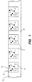
- FIG. 1 is a cross-sectional view of a photographic film replacement media 10 utilizing a preferred phosphor composition.
- the phosphor is preferably deposited into depressions 11 in a film 15.
- the phosphor is preferably mixed with an epoxy binder or equivalent material which is then applied to film 15.
- the phosphor includes three types of particles 12-14. However, the particles may be applied to the pits without a binder. For example, a mixture of the particles may be pressed into the pits and covered with a transparent layer.
- Each type of particle comprises a small crystal that is sensitized so as to release electrons into the conduction/communication band in response to a different range of visible wavelengths than the other types of particles.
- a backing material having depressions therein is preferred because the depressions prevent light from propagating parallel to the surface of the film. Such propagation during either image exposure or readout reduces the resolution of the film.
- An image storing phosphor having such depressions is described in co-pending U.S. patent application 08/287,433.
- the various types of phosphor particles are constructed by doping a base material with two dopants.
- the first dopant determines the sensitivity of the phosphor as a function of the wavelength of the light incident thereon.
- the second dopant determines the wavelength of the light that is to be used to read-out an image stored in the film.
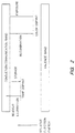
- Figure 2 is an energy level diagram for a preferred phosphor particle.
- the first dopant will be referred to as the color dopant in the following discussion.
- electrons are lifted into the conduction band of the crystal and diffuse to a site having the second dopant, referred to as the trap dopant in the following discussion.
- the sensitivity of the color dopant as function of incident light wavelength is determined by the particular dopant. Dopants that may be utilized to provide sensitivities in a number of wavelength ranges will be discussed in more detail below.
- the trap dopants are chosen to have an energy level that is closer to the conduction band than any of the color dopants. Thus, a trap may be readout without exciting any of the color dopant sites.
- the trapped electron is released by exposing the particle to light having the appropriate wavelength, the released electron recombines with an electron vacancy at one of the color dopant sites and generates a photon having a wavelength characteristic of the color dopant used.
- each particle type is responsible for recording a different color of light.
- each particle comprises a small crystal of a base material which has been doped with a color dopant and a trap dopant.
- Exemplary color dopants are Cu, Ag, Mn, O, Pb, Bi, Ce, Eu, Pr, Sm, Tb, Ho, Er, and Tm.
- Exemplary trap dopants are Sm, Bi, Sn, Fe, V, Ni, Pb, and Ag.
- Exemplary base materials are MgS, CaS, SrS, BaS, and ZnS and their mixtures such as (Ca, Sr)S.
- Other dopants and base materials, such as the selenides will be apparent to those skilled in the art.
- CaS doped with Eu as a color dopant and Sm as the trap dopant provides sensitivity to white light.
- ZnS doped with Cu as a color dopant and Pb as a trap dopant provides sensitivity to blue light as does: CaS:Cu, SrS:Cu, BaS:Ag, CaS:Bi, SrS:Bi.
- CaS with Mn as the color dopant and Sm as the trap dopant provides sensitivity to green light as does BaS:Mn, BaS:Cu, BaS:Bi. Yellow/orange sensitivity is provided by MgS:Eu, CaS:Eu, SrS:Eu.
- the trap dopant is not specified since it does not influence the spectral sensitivity.
- the concentration of the different dopants is maximized to give maximum sensitivity to the incident light and is in the atomic % range.
- each type of particle has a different trap dopant as well as a different color dopant. This arrangement allows the image to readout one color at a time. If all of the particles utilize the same trap dopant, then the readout beam stimulates all particles. The various intensities at the three colors must be determined simultaneously by observing the readout light intensity as a function of wavelength. It should be noted that the recombination spectra of one type of particle may overlap with the sensitivity spectra of a different type of particle, thus charging the second type of particle by the readout emission of the first type. This results in color distortion, therefore, each pixel's data must be corrected for the overlap between the existing recombination and sensitivity spectra. This computation increases the cost of the system.
- each type of particle can be readout separately.
- the particles having the trap dopant requiring the longest wavelength is readout first. Then the particles with the next longest readout wavelength are then readout, and so on.
- a single readout detector may be utilized and the above mentioned correction is no longer needed.
- a film replacement may be constructed by generating a thin film of the base crystal material on a backing and then doping the thin film using ion implantation techniques to provide the various dopants.
- Figure 3 is a highly magnified section of a thin film 100 having the various dopant atoms deposited thereon.
- the same trap dopant is utilized for each color receptor.
- Exemplary trap sites are indicated by the disks having the shading of the disk shown at 101.
- the color dopants are applied by implanting the three different types of color dopants.
- Exemplary color dopant sites are indicated by the disks having the shading of the disks shown at 102-104, respectively.
- the density of traps and color sites must be such that an electron leaving a color site will encounter an empty trap within a distance consistent with the desired spatial resolution of the film.
- an electron displaced from a trap must return to a site having the same color dopant as that from which it was originally released within an acceptable distance from the original dopant site.
- This set of conditions can be satisfied by an arrangement in which there are a large number of trap sites around each dopant site and the color dopant sites are clustered together for each type of color dopant.
- the implant pattern would duplicate the individual "particles" described above within the common base thin film. Clusters representing individual "particles" are shown at 110-112.
- the film thickness is mainly determined by the thickness of the layer which contains the sensitive material. This layer thickness is given by the lower of the absorption length of visible light in the sensitive material and the maximum practicable layer thickness in terms of bending and making a replacement film.
Landscapes
- Chemical & Material Sciences (AREA)
- Engineering & Computer Science (AREA)
- Materials Engineering (AREA)
- Inorganic Chemistry (AREA)
- Organic Chemistry (AREA)
- Physics & Mathematics (AREA)
- General Physics & Mathematics (AREA)
- Metallurgy (AREA)
- Luminescent Compositions (AREA)
- Silver Salt Photography Or Processing Solution Therefor (AREA)
- Non-Silver Salt Photosensitive Materials And Non-Silver Salt Photography (AREA)
Applications Claiming Priority (2)
| Application Number | Priority Date | Filing Date | Title |
|---|---|---|---|
| US08/338,922 US5622807A (en) | 1994-11-14 | 1994-11-14 | Phosphor film composition for use in image capture |
| US338922 | 1994-11-14 |
Publications (2)
| Publication Number | Publication Date |
|---|---|
| EP0712035A2 true EP0712035A2 (de) | 1996-05-15 |
| EP0712035A3 EP0712035A3 (de) | 1996-07-10 |
Family
ID=23326708
Family Applications (1)
| Application Number | Title | Priority Date | Filing Date |
|---|---|---|---|
| EP95307453A Withdrawn EP0712035A3 (de) | 1994-11-14 | 1995-10-19 | Lumineszierende Schichtzusammensetzung |
Country Status (3)
| Country | Link |
|---|---|
| US (1) | US5622807A (de) |
| EP (1) | EP0712035A3 (de) |
| JP (1) | JPH08304954A (de) |
Cited By (2)
| Publication number | Priority date | Publication date | Assignee | Title |
|---|---|---|---|---|
| EP0809146A1 (de) * | 1996-05-23 | 1997-11-26 | Hewlett-Packard Company | Photographisches Verfahren und photographische Vorrichtung |
| EP0814141A1 (de) * | 1996-06-17 | 1997-12-29 | Hewlett-Packard Company | Lumineszierende Schichtzusammensetzung mit Empfindlichkeit in Rot für Bildaufnahme |
Families Citing this family (6)
| Publication number | Priority date | Publication date | Assignee | Title |
|---|---|---|---|---|
| US6897999B1 (en) | 1998-11-25 | 2005-05-24 | The Research Foundation Of The University Of Central Florida | Optically written display |
| US6844387B2 (en) * | 1998-11-25 | 2005-01-18 | University Of Central Florida | Composites of inorganic luminophores stabilized in polymer hosts |
| USRE42076E1 (en) * | 1998-11-25 | 2011-01-25 | University Of Central Florida Research Foundation, Inc. | Composites of inorganic luminophores stabilized in polymer hosts |
| US7075707B1 (en) | 1998-11-25 | 2006-07-11 | Research Foundation Of The University Of Central Florida, Incorporated | Substrate design for optimized performance of up-conversion phosphors utilizing proper thermal management |
| US7804640B1 (en) | 2007-05-24 | 2010-09-28 | University Of Central Florida Research Foundation, Inc. | Composite cavity for enhanced efficiency of up-conversion |
| JP5236173B2 (ja) * | 2006-09-22 | 2013-07-17 | 独立行政法人物質・材料研究機構 | 可逆光応答素子を用いた並列アナログ演算装置 |
Citations (1)
| Publication number | Priority date | Publication date | Assignee | Title |
|---|---|---|---|---|
| US5065023A (en) | 1989-09-11 | 1991-11-12 | Quantex Corporation | Solid state high resolution photography and imaging using electron trapping materials |
Family Cites Families (12)
| Publication number | Priority date | Publication date | Assignee | Title |
|---|---|---|---|---|
| US2482813A (en) * | 1946-03-26 | 1949-09-27 | Eastman Kodak Co | Photorecording |
| DE2804127C2 (de) * | 1978-01-31 | 1984-03-08 | Siemens AG, 1000 Berlin und 8000 München | Verfahren zur Herstellung eines planen oder in einer Richtung gekrümmten Leuchtstoffschirmes für flache Farbbildanzeigegeräte |
| JPS59202100A (ja) * | 1983-04-30 | 1984-11-15 | コニカ株式会社 | 放射線画像変換パネル及びその製造方法 |
| US5028509A (en) * | 1984-09-14 | 1991-07-02 | Konica Corporation | Method for converting radiographic image, radiation energy storage panel having stimulable phosphor-containing layer and alkali halide phosphor |
| US5006366A (en) * | 1985-10-10 | 1991-04-09 | Quantex Corporation | Photoluminescent material for outputting orange light with reduced phosphorescence after charging and a process for making same |
| FR2605123B1 (fr) * | 1986-10-10 | 1989-07-07 | Bric | Objet fiduciaire ou de securite permettant une authentification visuelle ou optique |
| JPH02129600A (ja) * | 1988-11-09 | 1990-05-17 | Fujitsu Ltd | 放射線画像読取用螢光体板 |
| NL8802988A (nl) * | 1988-12-05 | 1990-07-02 | Philips Nv | Inrichting voor het met optische straling aftasten van een informatievlak. |
| IT1249543B (it) * | 1990-10-05 | 1995-02-28 | Minnesota Mining & Mfg | Metodo ed apparecchiatura per la lettura di un pannello di fosforo fotostimolabile |
| US5233183A (en) * | 1991-07-26 | 1993-08-03 | Itt Corporation | Color image intensifier device and method for producing same |
| US5245623A (en) * | 1991-12-02 | 1993-09-14 | Hughes Aircraft Company | Infrared-to-visible upconversion display system and method operable at room temperature |
| US5364747A (en) * | 1992-11-25 | 1994-11-15 | Eastman Kodak Company | Color correcting layers consisting essentially of at least one dye-forming coupler and gelatin in chromogenic black-and-white photographic imaging systems |
-
1994
- 1994-11-14 US US08/338,922 patent/US5622807A/en not_active Expired - Lifetime
-
1995
- 1995-10-19 EP EP95307453A patent/EP0712035A3/de not_active Withdrawn
- 1995-11-13 JP JP7318597A patent/JPH08304954A/ja active Pending
Patent Citations (1)
| Publication number | Priority date | Publication date | Assignee | Title |
|---|---|---|---|---|
| US5065023A (en) | 1989-09-11 | 1991-11-12 | Quantex Corporation | Solid state high resolution photography and imaging using electron trapping materials |
Cited By (2)
| Publication number | Priority date | Publication date | Assignee | Title |
|---|---|---|---|---|
| EP0809146A1 (de) * | 1996-05-23 | 1997-11-26 | Hewlett-Packard Company | Photographisches Verfahren und photographische Vorrichtung |
| EP0814141A1 (de) * | 1996-06-17 | 1997-12-29 | Hewlett-Packard Company | Lumineszierende Schichtzusammensetzung mit Empfindlichkeit in Rot für Bildaufnahme |
Also Published As
| Publication number | Publication date |
|---|---|
| EP0712035A3 (de) | 1996-07-10 |
| US5622807A (en) | 1997-04-22 |
| JPH08304954A (ja) | 1996-11-22 |
Similar Documents
| Publication | Publication Date | Title |
|---|---|---|
| EP0112469B2 (de) | Anwendung eines Energiedifferenzverfahrens zur Erzeugung von Strahlungsbildern unter Verwendung von Phosphorschichten sowie Phosphorschichten zusammen mit Filtern | |
| US4889990A (en) | Method and apparatus for recording and reproducing electron microscope image | |
| US4641267A (en) | Gradation correction curve creating method and apparatus | |
| JP3333278B2 (ja) | 放射線画像検出方法および放射線画像検出器 | |
| US7087915B2 (en) | Radiation image reproducing device and method for reproducing radiation image | |
| JPH02164067A (ja) | X線画像センサ | |
| DE2940454A1 (de) | Verfahren zur aufzeichnung eines strahlungsbildes auf einem aufzeichnungsmaterial | |
| US4983834A (en) | Large area particle detector system | |
| US5622807A (en) | Phosphor film composition for use in image capture | |
| US5629126A (en) | Phosphor film composition having sensitivity in the red for use in image capture | |
| JP3526891B2 (ja) | 放射線画像信号読出方法およびそれに用いられる放射線検出器 | |
| US6333513B1 (en) | Method for processing electric signals of radiographic image recorded in stimulable phosphor sheet | |
| JPH0772252A (ja) | 画像信号読出方法 | |
| JPH0727866A (ja) | 放射線検出器 | |
| US4952806A (en) | Noise erasing method for stimulable phosphor sheets | |
| EP0422581A2 (de) | Räumlicher Lichtmodulator mit Elektronen-einfangenden Materialien | |
| US5289204A (en) | Image recording apparatus | |
| Friedman | Imaging by random coverage | |
| JPH0261253B2 (de) | ||
| DE69431925T2 (de) | Farbbildwiedergabe | |
| EP0809146A1 (de) | Photographisches Verfahren und photographische Vorrichtung | |
| Shaw | Some detector characteristics of the photographic process | |
| JP3251737B2 (ja) | 画像信号読出方法 | |
| JPH02308238A (ja) | ディジタルx線撮像装置の画像読取り方式 | |
| JPH01309044A (ja) | 蓄積性蛍光体シート用カセッテ |
Legal Events
| Date | Code | Title | Description |
|---|---|---|---|
| PUAI | Public reference made under article 153(3) epc to a published international application that has entered the european phase |
Free format text: ORIGINAL CODE: 0009012 |
|
| AK | Designated contracting states |
Kind code of ref document: A2 Designated state(s): DE FR GB |
|
| PUAL | Search report despatched |
Free format text: ORIGINAL CODE: 0009013 |
|
| AK | Designated contracting states |
Kind code of ref document: A3 Designated state(s): DE FR GB |
|
| STAA | Information on the status of an ep patent application or granted ep patent |
Free format text: STATUS: THE APPLICATION IS DEEMED TO BE WITHDRAWN |
|
| 18D | Application deemed to be withdrawn |
Effective date: 19970111 |