EP0711003B1 - Bürstenloser drehbaren Verbinder - Google Patents
Bürstenloser drehbaren Verbinder Download PDFInfo
- Publication number
- EP0711003B1 EP0711003B1 EP95115957A EP95115957A EP0711003B1 EP 0711003 B1 EP0711003 B1 EP 0711003B1 EP 95115957 A EP95115957 A EP 95115957A EP 95115957 A EP95115957 A EP 95115957A EP 0711003 B1 EP0711003 B1 EP 0711003B1
- Authority
- EP
- European Patent Office
- Prior art keywords
- connector
- flexible printed
- housing
- ring
- disposed
- Prior art date
- Legal status (The legal status is an assumption and is not a legal conclusion. Google has not performed a legal analysis and makes no representation as to the accuracy of the status listed.)
- Expired - Lifetime
Links
- 230000008878 coupling Effects 0.000 claims description 4
- 238000010168 coupling process Methods 0.000 claims description 4
- 238000005859 coupling reaction Methods 0.000 claims description 4
- 239000003292 glue Substances 0.000 claims description 3
- 239000004593 Epoxy Substances 0.000 claims description 2
- 239000004020 conductor Substances 0.000 description 8
- 230000000712 assembly Effects 0.000 description 3
- 238000000429 assembly Methods 0.000 description 3
- 238000005516 engineering process Methods 0.000 description 3
- 238000004519 manufacturing process Methods 0.000 description 2
- 239000002184 metal Substances 0.000 description 2
- 238000000034 method Methods 0.000 description 2
- 229910001369 Brass Inorganic materials 0.000 description 1
- 239000010951 brass Substances 0.000 description 1
- 230000015556 catabolic process Effects 0.000 description 1
- 238000006731 degradation reaction Methods 0.000 description 1
- 238000011161 development Methods 0.000 description 1
- 230000018109 developmental process Effects 0.000 description 1
- 238000003754 machining Methods 0.000 description 1
- 239000000463 material Substances 0.000 description 1
- 230000013011 mating Effects 0.000 description 1
- 230000004297 night vision Effects 0.000 description 1
- 239000000758 substrate Substances 0.000 description 1
Images


Classifications
-
- H—ELECTRICITY
- H01—ELECTRIC ELEMENTS
- H01R—ELECTRICALLY-CONDUCTIVE CONNECTIONS; STRUCTURAL ASSOCIATIONS OF A PLURALITY OF MUTUALLY-INSULATED ELECTRICAL CONNECTING ELEMENTS; COUPLING DEVICES; CURRENT COLLECTORS
- H01R35/00—Flexible or turnable line connectors, i.e. the rotation angle being limited
- H01R35/04—Turnable line connectors with limited rotation angle with frictional contact members
-
- H—ELECTRICITY
- H01—ELECTRIC ELEMENTS
- H01R—ELECTRICALLY-CONDUCTIVE CONNECTIONS; STRUCTURAL ASSOCIATIONS OF A PLURALITY OF MUTUALLY-INSULATED ELECTRICAL CONNECTING ELEMENTS; COUPLING DEVICES; CURRENT COLLECTORS
- H01R12/00—Structural associations of a plurality of mutually-insulated electrical connecting elements, specially adapted for printed circuits, e.g. printed circuit boards [PCB], flat or ribbon cables, or like generally planar structures, e.g. terminal strips, terminal blocks; Coupling devices specially adapted for printed circuits, flat or ribbon cables, or like generally planar structures; Terminals specially adapted for contact with, or insertion into, printed circuits, flat or ribbon cables, or like generally planar structures
- H01R12/70—Coupling devices
- H01R12/77—Coupling devices for flexible printed circuits, flat or ribbon cables or like structures
- H01R12/78—Coupling devices for flexible printed circuits, flat or ribbon cables or like structures connecting to other flexible printed circuits, flat or ribbon cables or like structures
-
- H—ELECTRICITY
- H01—ELECTRIC ELEMENTS
- H01R—ELECTRICALLY-CONDUCTIVE CONNECTIONS; STRUCTURAL ASSOCIATIONS OF A PLURALITY OF MUTUALLY-INSULATED ELECTRICAL CONNECTING ELEMENTS; COUPLING DEVICES; CURRENT COLLECTORS
- H01R39/00—Rotary current collectors, distributors or interrupters
- H01R39/02—Details for dynamo electric machines
- H01R39/08—Slip-rings
- H01R39/10—Slip-rings other than with external cylindrical contact surface, e.g. flat slip-rings
Definitions
- the present invention relates to rotary connectors or slip rings, and more particularly, to a brushless rotary connector or slip ring employing flexprint circuits.
- a slip ring is designed and fabricated to transfer signals and power from a stationary housing to a revolving object such as a gimbal, or a commutator, or the like.
- Slip ring technology is about 40 years old and has proven to work well.
- conventional slip rings are labor intensive, are very expensive, and have reliability problems, such as when they experience vibration.
- Conventional slip rings are available from such manufacturers as Litton and Aeroflex, for example.
- Conventional slip rings typically employ brushes, springs and ball bearings, which adds to their complexity and cost. At high power levels, the brushes can burn during operation.
- a typical 24 conductor contact slip-ring connector has 128 parts, including rings, brushes, bearing, wires and housings. Also there is a limited amount of power that is typically transferred by conventional slip ring assemblies.
- Conventional commutator brushes are prone to burn-out and, are very heavy and relatively expensive. The majority of component failures of commutator brushes are due to the weaknesses in the brushes.
- Conventional cable wrap assemblies provide for limited distance and rotation. They are relatively heavy and large devices. They are also relatively expensive due to labor intensive fabrication operations. They also have a relatively short life span due to wear and tear of the cable. They experience a relatively high failure rate due to mishandling and alignment problems.
- US-A-4,870,311 discloses a wireless slip ring assembly with an inner subassembly in shape of an elongated hollow sleeve having a plurality of axially spaced anular slip rings the connection to which is lead via a circuit board arrangement disposed within said hollow sleeve. Furthermore, a cylindrical outer brush subassembly is provided to which a flexible printed circuit is attached on the exterior side of said cylindrical brush arrangement making the connection to the brushes cooperating with said slip rings of the hollow sleeve.
- This known slip ring assembly makes use of printed circuit technics for making connection to the brush system but cannot avoid thereby the above discussed problems.
- the present invention is a brushless rotary connector or slip ring.
- the brushless rotary connector comprises dimpled or bumped flexprint circuits, two plates that respectively secure the flexprint circuits, two housings that respectively house the plates and flexprint circuits, and in a preferred embodiment, two O-rings that interface between the respective housings and plates.
- the brushless rotary connector comprises a first housing, having a first relatively flat flexible printed circuit disposed therein.
- the first flexible printed circuit has a conductive contact disposed on a surface thereof.
- a first flexible cable is coupled to the conductive contact of the first flexible printed circuit for coupling electrical signals thereto and therefrom.
- a second housing comprises a second relatively flat flexible printed circuit that has at least a portion of a conductive ring disposed on a surface thereof.
- the second flexible printed circuit is disposed such that the conductive ring contacts the conductive contact of the first flexible printed circuit.
- a second flexible cable is coupled to the conductive ring of the second flexible printed circuit for coupling the electrical signals thereto and therefrom.
- a collar or other means for securing the first and second housings together is provided so that the conductive contact and ring properly contact each other.
- the first and second housings and first and second printed circuits are free to rotate relative to each other.
- the conductive contact and ring of the flexprint circuits maintain electrical contact with each other to couple the electrical signals through the connector.
- the brushless rotary connector was designed to transfer video signals and power from a stationary platform to a moving object without interrupting or limiting the revolution of the moving object at high or low speed.
- the connector of the present invention achieves this goal.
- the present brushless rotary connector employs no brushes, springs, or ball bearings. All moving electrical components are made using printed wiring technology that is used to produce the flexprint circuits.
- the brushless rotary connector uses flat slip rings (the flexible printed circuits) that are capable of operation at full military temperature (125° Celsius). The present connector has been tested and is capable of transferring current up to 15 amps.
- the brushless rotary connector provides for a cost effective alternative to conventional brush-type rotary connectors or slip rings.
- Fig. 1 illustrates a perspective view of an assembled brushless rotary connector 10, or slip ring 10, in accordance with the principles of the present invention.
- the brushless rotary connector 10 is comprised of first and second circular housings 11, 12 (top and bottom, respectively, in the drawing figures) that internally house first and second circular flexible printed circuits 27, 28 (shown in Figs. 2 and 3).
- a collar 16, such as a brass ring, for example, is used to secure the first and second circular housings 11, 12 together.
- the first (top) housing 11 has a top-hat shaped cross section that has a lip (not shown) and the collar 16 slides along the outer sidewall of the first housing 11 until it abuts the lip.
- the collar is then secured to the second (bottom) housing 12 by means of screws, for example.
- the first and second housings are free to rotate relative to each other, which is achieved using the first and second flexible printed circuits 27, 28, which slide relative to each other, as will be explained in more detail below.
- First and second flexible cables 13, 14 are internally coupled to the first and second flexible printed circuits 27, 28, respectively, and extend outside the respective first and second circular housings 11, 12 by way of openings (not shown).
- the first and second circular housings 11, 12 are rotatable relative to each other. Typically, one of the housings 11 is fixed while the other of the housings 12 is secured to a component that rotates.
- the components housed within the respective first and second circular housings 11, 12 are secured together in a routine manner by means of a plurality of screws and threaded holes, for example, and those for securing the components disposed within the first housing 11 are generally designated as 15.
- Figs. 2 and 3 show cross sectional side views of two embodiments of the brushless rotary connector 10 of Fig. 1.
- the embodiment of Fig. 2 employs dimples 31a as contacts 31 while the embodiment of Fig. 3 employs bumps 31b as the contacts 31.
- First and second circular metal plates 21, 22 are respectively disposed in recesses (not shown) in the first and second housings 11, 12.
- the first and second plates 21, 22 have O-rings 23 located in circular grooves 24 that respectively contact adjacent surfaces of the first and second housings 11, 12.
- the first and second plates 21, 22 have their adjacent surfaces disposed 0.010 inches to 0.020 inches apart to properly space the flexible printed circuits 27, 28 using a plurality of adjustable screws (not shown) located in the respective first and second housings 11, 12.
- the first and second plates 21, 22 are used to stiffen the first and second flexprint circuits 27, 28 so that they do not deform during operation.
- the plates 21, 22 may also be made of materials other than metal, but their purpose is to provide a strong substrate for the flexprint circuits 27, 28.
- the first and second plates 21, 22 are bonded by means of epoxy or glue, for example, or otherwise secured to the first and second flexprint circuits 27, 28, in a manner such that the metalized contacts 31 face each other.
- the first flexprint circuit 27 is fabricated to have metalized contacts 31 comprising bumps 31b (Fig. 3) or dimples 31a (Fig. 2) disposed on one surface thereof.
- the second flexprint circuit 28 is fabricated to have one or more metalized rings 33 (or portions thereof) disposed on one surface thereof. The respective metalized surfaces of the flexprint circuits 27, 28 with the contacts 31 and rings 33 disposed thereon are disposed in contact with each other as is shown in Figs. 2 and 3.
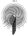
- An alignment pin 29 is provided to align the first and second flexprint circuits 27, 28 so that the contacts 31, 33 properly contact each other.
- the alignment pin 29 is generally located in the center of the flexprint circuits 27, 28, as is shown more clearly in Fig. 4, for example. As the two housings 11, 12 rotate with respect to each other the metalized contacts 31, 33 of the two flexprint circuits 27, 28 maintain electrical contact with each other.
- Fig. 4 shows an enlarged top view of the internal portion of the brushless rotary connector 10 illustrating details of the flexprint circuits 27, 28, and Fig. 5 shows a complete top view of the brushless rotary connector 10 shown in Fig. 4.
- the first flexprint circuit 27 containing the bumps 31b is disposed above the second flexprint circuit 28 containing the rings 33.
- the location of the O-ring groove 24 is shown in the second (lower) housing 12 along with the location of the alignment pin 29.
- the routing of conductors of the cable 13 to the bumps 31b is shown for clarity.
- Fig. 5 shows that the cable 13 is ultimately connected to a connector 17 which mates with a source of electrical signals, such as video or power signals, for example that are to be routed through the brushless rotary connector 10.
- the present invention may be used in many applications including night vision systems, radar system, helicopters, aircraft and spacecraft, for example, such as for rotating gimbals, and rotating antennas, and the like.
- the brushless rotary connector provides a next generation device for transferring signals and power between two associated parts where one moves and one is stationary.
- a 24 conductor contact rotary connector 10 includes only 9 parts. Of these nine, only two require precision machining. The cost of the rotary connector 10 in production is expected to be one-third that of a comparable conventional slip-ring assembly.
Landscapes
- Coupling Device And Connection With Printed Circuit (AREA)
Claims (9)
- Bürstenloser drehbarer Verbinder (10), enthaltend: ein erstes Gehäuse (11);eine erste, verhältnismäßig flache, flexible gedruckte Schaltung (27), welche in dem ersten Gehäuse (11) angeordnet ist und einen leitfähigen Kontakt (31) aufweist, der sich auf ihrer einen Oberfläche befindet;ein erstes flexibles Kabel (13), das mit dem leitfähigen Kontakt (31) der ersten flexiblen gedruckten Schaltung (27) gekoppelt ist, um elektrische Signale zu der Schaltung zu führen und von ihr abzuführen;ein zweites Gehäuse (12);eine zweite verhältnismäßig flache, flexible gedruckte Schaltung (28), die in dem zweiten Gehäuse (12) angeordnet ist und mindestens einen Teil eines leitfähigen Ringes (33) auf derjenigen Oberfläche aufweist, die in Kontakt mit dem leitfähigen Kontakt (31) der ersten flexiblen gedruckten Schaltung (27) steht;ein zweites flexibles Kabel (14), das mit dem leitfähigen Ring (33) der zweiten flexiblen gedruckten Schaltung (28) gekoppelt ist, um elektrische Signale zu dieser Schaltung zu führen und davon abzuführen; undMittel (16) zur Befestigung des ersten und zweiten Gehäuses (11, 12) aneinander, so daß der leitfähige Kontakt (31) und der Ring (33) einander berühren;wobei das erste und das zweite Gehäuse und die erste und zweite gedruckte Schaltung (27, 28) relativ zueinander frei drehbar sind, und wobei bei der Drehung der Gehäuse (11, 12) der leitfähige Kontakt (31) und der Ring (33) der flexiblen gedruckten Schaltungen (27, 28) miteinander elektrischen Kontakt halten, um die elektrischen Signale durch den Verbinder hindurch (10) zu übertragen.
- Verbinder (10) nach Anspruch 1, welcher weiter folgendes enthält:eine erste Platte (21), welche in dem ersten Gehäuse (11) angeordnet ist und einen Dichtungs-O-Ring (23) enthält, der an der benachbarten Oberfläche des ersten Gehäuses (11) ansteht, wobei die erste flexible gedruckte Schaltung (27) an der ersten Platte (21) befestigt ist; undeine zweite Platte (22), welche in dem zweiten Gehäuse (12) angeordnet ist und einen Dichtungs-O-Ring (23) enthält, der an der benachbarten Oberfläche des zweiten Gehäuses (12) ansteht, wobei die zweite flexible gedruckte Schaltung (28) an der zweiten Platte (22) befestigt ist.
- Verbinder (10) nach Anspruch 1, wobei die Kontakte (31) Aufwölbungen (31a) enthalten.
- Verbinder (10) nach Anspruch 1, bei dem die Kontakte (31) Höcker (31b) enthalten.
- Verbinder (10) nach Anspruch 1, wobei die erste und die zweite Platte (21, 22) mit ihren benachbarten Oberflächen in einem vorbestimmten Abstand voneinander gehalten sind, so daß sich die flexiblen gedruckten Schaltungen (27, 28) drehen können.
- Verbinder (10) nach Anspruch 2, wobei die erste und zweite Platte (21, 22) jeweils durch Epoxy oder Klebstoff befestigt sind.
- Verbinder (10) nach Anspruch 2, wobei die erste und zweite Platte (21, 22) durch Klebung befestigt sind.
- Verbinder (10) nach Anspruch 2, welcher weiter einen Ausrichtstift (29) zur Ausrichtung der ersten und der zweiten flexiblen gedruckten Schaltung (21, 22) in solcher Weise enthält, daß die Kontakte (31, 33) ordnungsgemäß miteinander Kontakt halten.
- Verbinder nach Anspruch 2 oder 5, welcher weiter einen Flansch (16) zum Festhalten des ersten und zweiten Gehäuses (11, 12) aneinander enthält, so daß der leitfähige Kontakt (31) und der Ring (33) miteinander Kontakt haben.
Applications Claiming Priority (2)
| Application Number | Priority Date | Filing Date | Title |
|---|---|---|---|
| US08/335,235 US5484294A (en) | 1994-11-07 | 1994-11-07 | Brushless rotary connector |
| US335235 | 1994-11-07 |
Publications (2)
| Publication Number | Publication Date |
|---|---|
| EP0711003A1 EP0711003A1 (de) | 1996-05-08 |
| EP0711003B1 true EP0711003B1 (de) | 1998-02-25 |
Family
ID=23310861
Family Applications (1)
| Application Number | Title | Priority Date | Filing Date |
|---|---|---|---|
| EP95115957A Expired - Lifetime EP0711003B1 (de) | 1994-11-07 | 1995-10-10 | Bürstenloser drehbaren Verbinder |
Country Status (5)
| Country | Link |
|---|---|
| US (1) | US5484294A (de) |
| EP (1) | EP0711003B1 (de) |
| JP (1) | JP2703527B2 (de) |
| DE (1) | DE69501655T2 (de) |
| IL (1) | IL115865A (de) |
Families Citing this family (24)
| Publication number | Priority date | Publication date | Assignee | Title |
|---|---|---|---|---|
| US5588843A (en) * | 1994-12-08 | 1996-12-31 | Hughes Aircraft Company | Rotary electrical connector |
| CA2176047C (en) * | 1995-05-22 | 2000-04-11 | Mohi Sobhani | Spring loaded rotary connector |
| US5690498A (en) * | 1996-09-23 | 1997-11-25 | He Holdings, Inc | Spring loaded rotary connector |
| US5899753A (en) * | 1997-04-03 | 1999-05-04 | Raytheon Company | Spring-loaded ball contact connector |
| US6400533B1 (en) * | 1999-06-30 | 2002-06-04 | Seagate Technology Llc | Disc drive actuator latch system for high rotational shock |
| US6386886B1 (en) * | 1999-09-09 | 2002-05-14 | Raytheon Company | Gimbal system |
| US6329059B1 (en) | 1999-11-12 | 2001-12-11 | Amsil Ltd. | Polymeric composition having self-extinguishing properties |
| US20040169434A1 (en) * | 2003-01-02 | 2004-09-02 | Washington Richard G. | Slip ring apparatus |
| US7071591B2 (en) * | 2003-01-02 | 2006-07-04 | Covi Technologies | Electromagnetic circuit and servo mechanism for articulated cameras |
| US20060057864A1 (en) * | 2004-09-13 | 2006-03-16 | Joseph Jeffrey A | Rotative electrical coupling |
| DE102004061580B3 (de) * | 2004-12-21 | 2006-11-23 | Siemens Ag | Röntgenuntersuchungsanordnung mit einem Flachdetektor |
| CN100421312C (zh) * | 2005-10-20 | 2008-09-24 | 明基电通股份有限公司 | 电性连接构造 |
| EP1984982A2 (de) * | 2006-02-09 | 2008-10-29 | LifeSync Corporation | Steckverbinder für gedruckte schaltung |
| US7602134B1 (en) | 2006-07-20 | 2009-10-13 | L-3 Communications Sonoma Eo, Inc. | Twist capsule for rotatable payload |
| US8325229B2 (en) * | 2008-11-26 | 2012-12-04 | Robert Bosch Gmbh | Camera having a slip ring and pan-tilt mechanism |
| US8529277B2 (en) | 2011-02-18 | 2013-09-10 | Hi Rel Connectors, Inc | Flex to flex connection device |
| WO2013141858A1 (en) * | 2012-03-21 | 2013-09-26 | Hi Rel Connectors, Inc. | Flex to flex connection device |
| US8821167B2 (en) | 2012-05-31 | 2014-09-02 | Hi Rel Connectors, Inc. | Apparatus for electrically connecting a flexible circuit to a receiver |
| CN103944029B (zh) * | 2014-04-30 | 2015-12-30 | 北京航天控制仪器研究所 | 一种支撑与信号传递一体化轴系 |
| KR102531872B1 (ko) | 2016-06-21 | 2023-05-11 | 유니버셜 인스트루먼츠 코퍼레이션 | 조립 기계를 위한 슬립 트랙 구조, 시스템 및 방법 |
| CN106099598B (zh) * | 2016-07-22 | 2018-11-09 | 大连华锐重工集团股份有限公司 | 高压电滑环碟刹式导电组件 |
| US10116103B1 (en) * | 2017-12-17 | 2018-10-30 | Satyajit Patwardhan | Power connector with integrated disconnect |
| CN215732537U (zh) * | 2021-07-23 | 2022-02-01 | 东莞市承越电子科技有限公司 | 单向随意拉数据线 |
| DE102021124213A1 (de) | 2021-09-20 | 2023-03-23 | Swoboda Wiggensbach KG | Stecker für Laderoboter |
Family Cites Families (8)
| Publication number | Priority date | Publication date | Assignee | Title |
|---|---|---|---|---|
| GB1057888A (en) * | 1962-10-23 | 1967-02-08 | Sperry Gyroscope Co Ltd | Contact assemblies |
| DE2064993A1 (de) * | 1970-10-23 | 1972-05-18 | Sprague Electric Co , North Adams Mass (V St A ) | Elektrischer Kontakt Ausscheidung aus 2052072 |
| US4870311A (en) * | 1988-10-11 | 1989-09-26 | Honeywell Inc. | Wireless slip ring assembly |
| DE9100050U1 (de) * | 1991-01-04 | 1991-03-28 | Mangold, Hermann, 7959 Kirchberg | Kabeltrommel für das beim Fechten verwendete elektrische Treffer-Anzeigesystem |
| US5147208A (en) * | 1991-06-28 | 1992-09-15 | Rogers Corporation | Flexible printed circuit with raised contacts |
| US5195898A (en) * | 1992-01-17 | 1993-03-23 | The United States Of America As Represented By The Secretary Of The Army | Non-shearing connectors for flexible circuits |
| US5288235A (en) * | 1992-12-14 | 1994-02-22 | Hughes Aircraft Company | Electrical interconnects having a supported bulge configuration |
| US5409403A (en) * | 1993-10-25 | 1995-04-25 | Falossi; Aldo | 360 degree connector system |
-
1994
- 1994-11-07 US US08/335,235 patent/US5484294A/en not_active Expired - Fee Related
-
1995
- 1995-10-10 DE DE69501655T patent/DE69501655T2/de not_active Expired - Fee Related
- 1995-10-10 EP EP95115957A patent/EP0711003B1/de not_active Expired - Lifetime
- 1995-11-02 IL IL11586595A patent/IL115865A/en active IP Right Grant
- 1995-11-07 JP JP7288410A patent/JP2703527B2/ja not_active Expired - Fee Related
Also Published As
| Publication number | Publication date |
|---|---|
| EP0711003A1 (de) | 1996-05-08 |
| US5484294A (en) | 1996-01-16 |
| JP2703527B2 (ja) | 1998-01-26 |
| DE69501655D1 (de) | 1998-04-02 |
| IL115865A (en) | 1998-08-16 |
| DE69501655T2 (de) | 1998-10-08 |
| JPH08213135A (ja) | 1996-08-20 |
| IL115865A0 (en) | 1996-01-31 |
Similar Documents
| Publication | Publication Date | Title |
|---|---|---|
| EP0711003B1 (de) | Bürstenloser drehbaren Verbinder | |
| US7002269B2 (en) | Slip ring unit with a printed circuit board | |
| US8348677B2 (en) | Slip-ring unit | |
| US5866967A (en) | Slip ring mechanism of non-sliding type | |
| JP6947874B2 (ja) | 導電スリップリング | |
| EP0716481B1 (de) | Drehbarer elektrischen Verbinder | |
| CA1155508A (en) | Multi-channel rotary electrical conductor assembly | |
| KR100211274B1 (ko) | 볼 접촉식 회전 커넥터 | |
| EP0863587A1 (de) | Drehbarer Verbinder mit Rillen/Kugeln | |
| US5453753A (en) | Mechanically steerable modular planar patch array antenna | |
| US6663395B2 (en) | Electrical joint employing conductive slurry | |
| US4465951A (en) | Backup bearing and power transfer assembly for communication satellite | |
| US6132219A (en) | Planetary connector | |
| US2523081A (en) | Gyroscope electrical connection apparatus | |
| CN209747874U (zh) | 导电滑环 | |
| CN117601107A (zh) | 一种可连续回转的单元模块及模块化机器人 | |
| US3386069A (en) | Electrical connectors | |
| RU176770U1 (ru) | Горизонтальное вращающееся контактное устройство для оптико-электронной системы (ВКУ-ОЭС-ГН) | |
| US4779469A (en) | Power and signal transfer unit | |
| CN223141077U (zh) | 采样线束连接装置 | |
| CN119050764A (zh) | 有限角度滚动汇流环装置 | |
| CN118472732A (zh) | 导电滑环及随钻测井仪器 | |
| RU2662220C2 (ru) | Токопередающий элемент | |
| SU736231A1 (ru) | Устройство дл подвода электрического тока к вращающемус приемнику | |
| CN113945739A (zh) | 接口装置、电路板单元、半导体测试设备 |
Legal Events
| Date | Code | Title | Description |
|---|---|---|---|
| PUAI | Public reference made under article 153(3) epc to a published international application that has entered the european phase |
Free format text: ORIGINAL CODE: 0009012 |
|
| AK | Designated contracting states |
Kind code of ref document: A1 Designated state(s): DE ES FR GB IT |
|
| 17P | Request for examination filed |
Effective date: 19961104 |
|
| 17Q | First examination report despatched |
Effective date: 19961227 |
|
| GRAG | Despatch of communication of intention to grant |
Free format text: ORIGINAL CODE: EPIDOS AGRA |
|
| GRAG | Despatch of communication of intention to grant |
Free format text: ORIGINAL CODE: EPIDOS AGRA |
|
| GRAH | Despatch of communication of intention to grant a patent |
Free format text: ORIGINAL CODE: EPIDOS IGRA |
|
| GRAH | Despatch of communication of intention to grant a patent |
Free format text: ORIGINAL CODE: EPIDOS IGRA |
|
| GRAA | (expected) grant |
Free format text: ORIGINAL CODE: 0009210 |
|
| AK | Designated contracting states |
Kind code of ref document: B1 Designated state(s): DE ES FR GB IT |
|
| PG25 | Lapsed in a contracting state [announced via postgrant information from national office to epo] |
Ref country code: IT Free format text: LAPSE BECAUSE OF FAILURE TO SUBMIT A TRANSLATION OF THE DESCRIPTION OR TO PAY THE FEE WITHIN THE PRE;WARNING: LAPSES OF ITALIAN PATENTS WITH EFFECTIVE DATE BEFORE 2007 MAY HAVE OCCURRED AT ANY TIME BEFORE 2007. THE CORRECT EFFECTIVE DATE MAY BE DIFFERENT FROM THE ONE RECORDED.SCRIBED TIME-LIMIT Effective date: 19980225 Ref country code: ES Free format text: THE PATENT HAS BEEN ANNULLED BY A DECISION OF A NATIONAL AUTHORITY Effective date: 19980225 |
|
| REF | Corresponds to: |
Ref document number: 69501655 Country of ref document: DE Date of ref document: 19980402 |
|
| ET | Fr: translation filed | ||
| PLBE | No opposition filed within time limit |
Free format text: ORIGINAL CODE: 0009261 |
|
| STAA | Information on the status of an ep patent application or granted ep patent |
Free format text: STATUS: NO OPPOSITION FILED WITHIN TIME LIMIT |
|
| RAP2 | Party data changed (patent owner data changed or rights of a patent transferred) |
Owner name: RAYTHEON COMPANY |
|
| 26N | No opposition filed | ||
| REG | Reference to a national code |
Ref country code: GB Ref legal event code: 732E |
|
| REG | Reference to a national code |
Ref country code: FR Ref legal event code: TP Ref country code: FR Ref legal event code: CD Ref country code: FR Ref legal event code: CA |
|
| REG | Reference to a national code |
Ref country code: GB Ref legal event code: IF02 |
|
| PGFP | Annual fee paid to national office [announced via postgrant information from national office to epo] |
Ref country code: FR Payment date: 20030911 Year of fee payment: 9 |
|
| PGFP | Annual fee paid to national office [announced via postgrant information from national office to epo] |
Ref country code: GB Payment date: 20030916 Year of fee payment: 9 |
|
| PGFP | Annual fee paid to national office [announced via postgrant information from national office to epo] |
Ref country code: DE Payment date: 20030924 Year of fee payment: 9 |
|
| PG25 | Lapsed in a contracting state [announced via postgrant information from national office to epo] |
Ref country code: GB Free format text: LAPSE BECAUSE OF NON-PAYMENT OF DUE FEES Effective date: 20041010 |
|
| PG25 | Lapsed in a contracting state [announced via postgrant information from national office to epo] |
Ref country code: DE Free format text: LAPSE BECAUSE OF NON-PAYMENT OF DUE FEES Effective date: 20050503 |
|
| GBPC | Gb: european patent ceased through non-payment of renewal fee |
Effective date: 20041010 |
|
| PG25 | Lapsed in a contracting state [announced via postgrant information from national office to epo] |
Ref country code: FR Free format text: LAPSE BECAUSE OF NON-PAYMENT OF DUE FEES Effective date: 20050630 |
|
| REG | Reference to a national code |
Ref country code: FR Ref legal event code: ST |