EP0709577B1 - A valve having four connection ports and two positions - Google Patents
A valve having four connection ports and two positions Download PDFInfo
- Publication number
- EP0709577B1 EP0709577B1 EP19950440070 EP95440070A EP0709577B1 EP 0709577 B1 EP0709577 B1 EP 0709577B1 EP 19950440070 EP19950440070 EP 19950440070 EP 95440070 A EP95440070 A EP 95440070A EP 0709577 B1 EP0709577 B1 EP 0709577B1
- Authority
- EP
- European Patent Office
- Prior art keywords
- port
- orifice
- valve
- connection
- return valve
- Prior art date
- Legal status (The legal status is an assumption and is not a legal conclusion. Google has not performed a legal analysis and makes no representation as to the accuracy of the status listed.)
- Expired - Lifetime
Links
Images

Classifications
-
- F—MECHANICAL ENGINEERING; LIGHTING; HEATING; WEAPONS; BLASTING
- F15—FLUID-PRESSURE ACTUATORS; HYDRAULICS OR PNEUMATICS IN GENERAL
- F15B—SYSTEMS ACTING BY MEANS OF FLUIDS IN GENERAL; FLUID-PRESSURE ACTUATORS, e.g. SERVOMOTORS; DETAILS OF FLUID-PRESSURE SYSTEMS, NOT OTHERWISE PROVIDED FOR
- F15B11/00—Servomotor systems without provision for follow-up action; Circuits therefor
- F15B11/02—Systems essentially incorporating special features for controlling the speed or actuating force of an output member
- F15B11/024—Systems essentially incorporating special features for controlling the speed or actuating force of an output member by means of differential connection of the servomotor lines, e.g. regenerative circuits
-
- F—MECHANICAL ENGINEERING; LIGHTING; HEATING; WEAPONS; BLASTING
- F15—FLUID-PRESSURE ACTUATORS; HYDRAULICS OR PNEUMATICS IN GENERAL
- F15B—SYSTEMS ACTING BY MEANS OF FLUIDS IN GENERAL; FLUID-PRESSURE ACTUATORS, e.g. SERVOMOTORS; DETAILS OF FLUID-PRESSURE SYSTEMS, NOT OTHERWISE PROVIDED FOR
- F15B2211/00—Circuits for servomotor systems
- F15B2211/30—Directional control
- F15B2211/305—Directional control characterised by the type of valves
- F15B2211/30505—Non-return valves, i.e. check valves
-
- F—MECHANICAL ENGINEERING; LIGHTING; HEATING; WEAPONS; BLASTING
- F15—FLUID-PRESSURE ACTUATORS; HYDRAULICS OR PNEUMATICS IN GENERAL
- F15B—SYSTEMS ACTING BY MEANS OF FLUIDS IN GENERAL; FLUID-PRESSURE ACTUATORS, e.g. SERVOMOTORS; DETAILS OF FLUID-PRESSURE SYSTEMS, NOT OTHERWISE PROVIDED FOR
- F15B2211/00—Circuits for servomotor systems
- F15B2211/30—Directional control
- F15B2211/305—Directional control characterised by the type of valves
- F15B2211/30525—Directional control valves, e.g. 4/3-directional control valve
-
- F—MECHANICAL ENGINEERING; LIGHTING; HEATING; WEAPONS; BLASTING
- F15—FLUID-PRESSURE ACTUATORS; HYDRAULICS OR PNEUMATICS IN GENERAL
- F15B—SYSTEMS ACTING BY MEANS OF FLUIDS IN GENERAL; FLUID-PRESSURE ACTUATORS, e.g. SERVOMOTORS; DETAILS OF FLUID-PRESSURE SYSTEMS, NOT OTHERWISE PROVIDED FOR
- F15B2211/00—Circuits for servomotor systems
- F15B2211/30—Directional control
- F15B2211/31—Directional control characterised by the positions of the valve element
- F15B2211/3122—Special positions other than the pump port being connected to working ports or the working ports being connected to the return line
- F15B2211/3127—Floating position connecting the working ports and the return line
-
- F—MECHANICAL ENGINEERING; LIGHTING; HEATING; WEAPONS; BLASTING
- F15—FLUID-PRESSURE ACTUATORS; HYDRAULICS OR PNEUMATICS IN GENERAL
- F15B—SYSTEMS ACTING BY MEANS OF FLUIDS IN GENERAL; FLUID-PRESSURE ACTUATORS, e.g. SERVOMOTORS; DETAILS OF FLUID-PRESSURE SYSTEMS, NOT OTHERWISE PROVIDED FOR
- F15B2211/00—Circuits for servomotor systems
- F15B2211/30—Directional control
- F15B2211/315—Directional control characterised by the connections of the valve or valves in the circuit
- F15B2211/3157—Directional control characterised by the connections of the valve or valves in the circuit being connected to a pressure source, an output member and a return line
- F15B2211/31576—Directional control characterised by the connections of the valve or valves in the circuit being connected to a pressure source, an output member and a return line having a single pressure source and a single output member
-
- F—MECHANICAL ENGINEERING; LIGHTING; HEATING; WEAPONS; BLASTING
- F15—FLUID-PRESSURE ACTUATORS; HYDRAULICS OR PNEUMATICS IN GENERAL
- F15B—SYSTEMS ACTING BY MEANS OF FLUIDS IN GENERAL; FLUID-PRESSURE ACTUATORS, e.g. SERVOMOTORS; DETAILS OF FLUID-PRESSURE SYSTEMS, NOT OTHERWISE PROVIDED FOR
- F15B2211/00—Circuits for servomotor systems
- F15B2211/30—Directional control
- F15B2211/32—Directional control characterised by the type of actuation
- F15B2211/329—Directional control characterised by the type of actuation actuated by fluid pressure
-
- F—MECHANICAL ENGINEERING; LIGHTING; HEATING; WEAPONS; BLASTING
- F15—FLUID-PRESSURE ACTUATORS; HYDRAULICS OR PNEUMATICS IN GENERAL
- F15B—SYSTEMS ACTING BY MEANS OF FLUIDS IN GENERAL; FLUID-PRESSURE ACTUATORS, e.g. SERVOMOTORS; DETAILS OF FLUID-PRESSURE SYSTEMS, NOT OTHERWISE PROVIDED FOR
- F15B2211/00—Circuits for servomotor systems
- F15B2211/70—Output members, e.g. hydraulic motors or cylinders or control therefor
- F15B2211/705—Output members, e.g. hydraulic motors or cylinders or control therefor characterised by the type of output members or actuators
- F15B2211/7051—Linear output members
- F15B2211/7053—Double-acting output members
- F15B2211/7054—Having equal piston areas
-
- Y—GENERAL TAGGING OF NEW TECHNOLOGICAL DEVELOPMENTS; GENERAL TAGGING OF CROSS-SECTIONAL TECHNOLOGIES SPANNING OVER SEVERAL SECTIONS OF THE IPC; TECHNICAL SUBJECTS COVERED BY FORMER USPC CROSS-REFERENCE ART COLLECTIONS [XRACs] AND DIGESTS
- Y10—TECHNICAL SUBJECTS COVERED BY FORMER USPC
- Y10T—TECHNICAL SUBJECTS COVERED BY FORMER US CLASSIFICATION
- Y10T137/00—Fluid handling
- Y10T137/2496—Self-proportioning or correlating systems
- Y10T137/2544—Supply and exhaust type
- Y10T137/2554—Reversing or 4-way valve systems
Definitions
- the present invention relates to a valve with four connection orifices and two positions intended, in one of its positions, to supply at least one organ to animate and, in the other position, to put in communication at least two chambers of said organ (s), the pressure therein being low or even almost zero, regardless of the main circuit operating pressure or the pressure directly supplied by the fluid supply source.
- valve according to the invention When the valve according to the invention is in the first position, it is therefore possible to supply the organ (s) with a certain pressure, then to maintain this pressure thanks to the first non-return valve.
- a third non-return valve allowing only the circulation of the fluid of the second port to the second connection port.
- This third valve of non-return thus isolates the organ (s) from any pressure build-up which may appear at the second connection orifice when the valve (or more exactly the distributor of this one) is in the first position.
- At least one non-return valves may be of the "spring loaded” type.
- Preferably to minus the second non-return valve will be of the "spring loaded” type.
- the two the dispenser positions may advantageously be lockable by means of a locking device.
- this locking device will be a mechanical locking device.
- provision may be made for the locking of the two positions is done automatically. It may also be provided that the unlocking of said positions is done automatically.
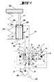
- the valve (1) according to the invention shown schematically in Figures 1 and 2, has four connection holes (A, B, C, D).
- the first opening of connection (A) and the second connection orifice (B) are connected to a fluid supply source (2).
- the third port (C) and the fourth port (D), for their part, are connected to a member (3) to be animated.
- the valve (1) also comprises a distributor (4) with four orifices (A ', B ', C', D ') and two positions (5, 6).
- the first opening (A ') is directly in communication with the first connection orifice (A).
- the third opening (C ') is directly in communication with the third connection orifice (VS).
- the fourth opening (D ') is in direct communication with the fourth connection orifice (D).
- the distributor (4) has two channels (7, 8).
- the first channel (7) which allows the first port to be put into communication (A ') and the third orifice (C'), includes a non-return valve (9) allowing only the circulation of the fluid from the first port (A ') to the third port (VS').
- This first non-return valve (9) is a non-return valve of the type "with spring ".
- the second channel (8) for its part, allows the free circulation of the fluid between the second orifice (B ') and the fourth orifice (D').
- the distributor (4) has two other channels: a third channel (10) which puts the third orifice (C ') directly in communication with the fourth orifice (D ') so that the fluid can circulate freely between these two orifices (C 'and D'), and a fourth channel (11) allowing to put the first port (A ') and the third channel (10) into communication.
- This fourth channel (11) has a second non-return valve (12) allowing only the circulation of the fluid from the third channel (10) to the first orifice (AT').
- This second non-return valve (12) is also a non-return valve. of the "with spring" type.
- the second opening (B ') is closed in the second position (6).
- the valve (1) also includes a third non-return valve (15) implanted between the second connection orifice (B) and the second orifice (B ').
- This valve non-return (15) only allows the circulation of the fluid of the second orifice (B ') to the second connection orifice (B).
- This third valve of non-return valve (15) is also a non-return valve of the "with spring" type.
- this valve (1) will appear clearly in the following description of an example of use with a double rod cylinder (16) (17).
- the first chamber (18) of this jack (16) is connected to the third connection orifice (C) by a first pipe (19), while the second chamber (20) of said cylinder (16) is connected to the fourth connection orifice (D) by a second line (21).
- the pressure supplied by the pump (23) at the first connection orifice (A) automatically deactivates the locking device (14), then the control by the control device (13) of the placing of the distributor (4) in its first position (5).
- the locking device (14) again automatically locks the dispenser (4) in this new position.
- the fluid delivered by the pump (23) opens the first non-return valve (9), circulates in the first pipe (19) and enters in the first chamber (18) of the jack (16). In doing so, this fluid repels the rod (17)-piston (25) assembly in the cylinder (26) to lift the mass (22).
- the piston (25) expels the fluid contained in the second chamber (20) of the jack (16), which fluid circulates in the second pipe (21) and the second way (8), opens the third non-return valve (15) and flows into the reservoir (24) of the fluid supply source (2).
- the pressure prevailing in the first chamber (18) of the jack (16) is held by the first non-return valve (9).
- the third non-return valve (15) isolates the second chamber (20) of the jack (16) of any pressure build-up which can appear at the second connection orifice (B).
- valve (1) which has just been described, may be devoid of the third non-return valve (15) when, in the first position (5), it it is not necessary to isolate the second chamber (20) of the jack (16) from any pressure build-up which may appear at the second connection orifice (B).
- valve of the invention can be used in other applications than the one just described (hydraulic or pneumatic).
- the calibration value of the non-return valves (9, 12 and 15) depends on the use of the valve. A whole range of valves can thus be created with different taring values.
- the second non-return valve (12) will be a valve. non-return with spring.
- first connection orifice (A) and / or the third connection port (C) and / or the fourth connection orifice (D) will be (will) be confused with the first port (A ') and / or the third port (C') and / or the fourth port (D ').
- the control device (13) can be of any configuration since it allows the distributor (4) to be put in its first position (5) and in its second position (6).
- the locking device (14) may also be of a configuration any where it allows the distributor (4) to be locked in each of its two positions (5 and 6).
Description
La présente invention concerne une valve à quatre orifices de raccordement et deux positions destinée, dans l'une de ses positions, à alimenter au moins un organe à animer et, dans l'autre position, à mettre en communication au moins deux chambres dudit (desdits) organe(s), la pression y régnant étant faible voire quasi nulle, quelle que soit la pression de service du circuit principal ou la pression directement fournie par la source d'alimentation en fluide.The present invention relates to a valve with four connection orifices and two positions intended, in one of its positions, to supply at least one organ to animate and, in the other position, to put in communication at least two chambers of said organ (s), the pressure therein being low or even almost zero, regardless of the main circuit operating pressure or the pressure directly supplied by the fluid supply source.
A cet effet, la valve selon l'invention comporte :
- à quatre orifices dont un premier orifice, un troisième orifice et un quatrième orifice sont directement en communication ou sont confondus respectivement avec le premier orifice de raccordement, le troisième orifice de raccordement et le quatrième orifice de raccordement, et
- à deux positions pouvant être rendues opérationnelles au moyen d'un dispositif
de commande :
- une première position dans laquelle un premier clapet de non-retour permet uniquement la circulation du fluide du premier orifice vers le troisième orifice, tandis qu'un deuxième orifice et le quatrième orifice sont directement en communication l'un avec l'autre,
- une deuxième position dans laquelle le troisième orifice et le quatrième orifice sont directement en communication l'un avec l'autre, tandis qu'un deuxième clapet de non-retour permet uniquement la circulation du fluide dudit troisième orifice et dudit quatrième orifice en communication vers le premier orifice.
- with four orifices of which a first orifice, a third orifice and a fourth orifice are directly in communication or are merged respectively with the first connection orifice, the third connection orifice and the fourth connection orifice, and
- with two positions that can be made operational by means of a control device:
- a first position in which a first non-return valve only allows the circulation of the fluid from the first orifice to the third orifice, while a second orifice and the fourth orifice are directly in communication with each other,
- a second position in which the third orifice and the fourth orifice are directly in communication with one another, while a second check valve only allows the circulation of the fluid from said third orifice and from said fourth orifice in communication with the first opening.
Lorsque la valve selon l'invention se trouve dans la première position, il est donc possible d'alimenter l' (les) organe(s) avec une certaine pression, puis de maintenir cette pression grâce au premier clapet de non-retour.When the valve according to the invention is in the first position, it is therefore possible to supply the organ (s) with a certain pressure, then to maintain this pressure thanks to the first non-return valve.
Lorsque la valve est mise dans sa deuxième position au moyen du dispositif de commande, il est possible, grâce à la mise en communication du troisième orifice et du quatrième orifice et grâce à la présence du deuxième clapet de non-retour, de mettre en communication au moins deux chambres dudit (desdits) organe(s), la pression régnant alors dans lesdites chambres en communication étant faible, voire quasi nulle. When the valve is put in its second position by means of the device control, it is possible, thanks to the communication of the third port and the fourth port and thanks to the presence of the second non-return valve, to connect at least two chambers of said (said) organ (s), the pressure then prevailing in said communicating chambers being weak, even almost zero.
Selon une caractéristique supplémentaire de l'invention, il est prévu un troisième clapet de non-retour permettant uniquement la circulation du fluide du deuxième orifice vers le deuxième orifice de raccordement. Ce troisième clapet de non-retour isole ainsi l' (les) organe(s) des éventuelles montées en pression pouvant apparaítre au deuxième orifice de raccordement lorsque la valve (ou plus exactement le distributeur de celle-ci) se trouve dans la première position.According to an additional characteristic of the invention, there is provided a third non-return valve allowing only the circulation of the fluid of the second port to the second connection port. This third valve of non-return thus isolates the organ (s) from any pressure build-up which may appear at the second connection orifice when the valve (or more exactly the distributor of this one) is in the first position.
Selon une autre caractéristique supplémentaire de l'invention, l'un au moins des clapets de non-retour pourra être du type "avec ressort". Préférentiellement au moins le deuxième clapet de non-retour sera du type "avec ressort".According to another additional characteristic of the invention, at least one non-return valves may be of the "spring loaded" type. Preferably to minus the second non-return valve will be of the "spring loaded" type.
Selon une autre caractéristique supplémentaire de l'invention, les deux positions du distributeur pourront, avantageusement, être verrouillables au moyen d'un dispositif de verrouillage. De préférence, ce dispositif de verrouillage sera un dispositif de verrouillage mécanique.According to another additional characteristic of the invention, the two the dispenser positions may advantageously be lockable by means of a locking device. Preferably, this locking device will be a mechanical locking device.
Avantageusement, il pourra être prévu que le verrouillage des deux positions se fasse automatiquement. Il pourra en sus également être prévu que le déverrouillage desdites positions se fasse automatiquement.Advantageously, provision may be made for the locking of the two positions is done automatically. It may also be provided that the unlocking of said positions is done automatically.
Selon une autre caractéristique supplémentaire de l'invention, le dispositif de commande pourra piloter la mise du distributeur :
- dans la première position à partir de la pression régnant au premier orifice de raccordement, et
- dans la deuxième position à partir de la pression régnant au deuxième orifice de raccordement.
- in the first position from the pressure prevailing at the first connection orifice, and
- in the second position from the pressure prevailing at the second connection orifice.
L'invention sera bien comprise grâce à la description suivante d'un exemple de réalisation non limitatif de la valve et d'une utilisation non limitative de celle-ci. Cette description est faite en se référant au dessin annexé sur lequel :
- la figure 1 représente la valve selon l'invention lorsque le distributeur se trouve dans sa première position ;
- la figure 2 représente la valve selon l'invention lorsque le distributeur se trouve dans sa deuxième position.
- Figure 1 shows the valve according to the invention when the dispenser is in its first position;
- Figure 2 shows the valve according to the invention when the dispenser is in its second position.
La valve (1) selon l'invention représentée schématiquement sur les figures 1 et 2, comporte quatre orifices de raccordement (A, B, C, D). Le premier orifice de raccordement (A) et le deuxième orifice de raccordement (B) sont raccordés à une source d'alimentation (2) en fluide. Le troisième orifice (C) et le quatrième orifice (D), quant à eux, sont raccordés à un organe (3) à animer.The valve (1) according to the invention shown schematically in Figures 1 and 2, has four connection holes (A, B, C, D). The first opening of connection (A) and the second connection orifice (B) are connected to a fluid supply source (2). The third port (C) and the fourth port (D), for their part, are connected to a member (3) to be animated.
La valve (1) comporte également un distributeur (4) à quatre orifices (A', B', C', D') et deux positions (5, 6). Le premier orifice (A') est directement en communication avec le premier orifice de raccordement (A). Le troisième orifice (C') est directement en communication avec le troisième orifice de raccordement (C). Le quatrième orifice (D') est directement en communication avec le quatrième orifice de raccordement (D).The valve (1) also comprises a distributor (4) with four orifices (A ', B ', C', D ') and two positions (5, 6). The first opening (A ') is directly in communication with the first connection orifice (A). The third opening (C ') is directly in communication with the third connection orifice (VS). The fourth opening (D ') is in direct communication with the fourth connection orifice (D).
Dans la première position (5), le distributeur (4) comporte deux voies (7, 8). La première voie (7) qui permet de mettre en communication le premier orifice (A') et le troisième orifice (C'), comporte un clapet de non-retour (9) autorisant uniquement la circulation du fluide du premier orifice (A') vers le troisième orifice (C'). Ce premier clapet de non-retour (9) est un clapet de non-retour du type "avec ressort". La deuxième voie (8), quant à elle, autorise la libre circulation du fluide entre le deuxième orifice (B') et le quatrième orifice (D').In the first position (5), the distributor (4) has two channels (7, 8). The first channel (7) which allows the first port to be put into communication (A ') and the third orifice (C'), includes a non-return valve (9) allowing only the circulation of the fluid from the first port (A ') to the third port (VS'). This first non-return valve (9) is a non-return valve of the type "with spring ". The second channel (8), for its part, allows the free circulation of the fluid between the second orifice (B ') and the fourth orifice (D').
Dans la deuxième position (6), le distributeur (4) comporte deux autres voies : une troisième voie (10) qui met le troisième orifice (C') directement en communication avec le quatrième orifice (D') de sorte que le fluide puisse circuler librement entre ces deux orifices (C' et D'), et une quatrième voie (11) permettant de mettre en communication le premier orifice (A') et la troisième voie (10). Cette quatrième voie (11) comporte un deuxième clapet de non-retour (12) autorisant uniquement la circulation du fluide de la troisième voie (10) vers le premier orifice (A'). Ce deuxième clapet de non-retour (12) est également un clapet de non-retour du type "avec ressort". Le deuxième orifice (B'), quant à lui, est fermé dans la deuxième position (6).In the second position (6), the distributor (4) has two other channels: a third channel (10) which puts the third orifice (C ') directly in communication with the fourth orifice (D ') so that the fluid can circulate freely between these two orifices (C 'and D'), and a fourth channel (11) allowing to put the first port (A ') and the third channel (10) into communication. This fourth channel (11) has a second non-return valve (12) allowing only the circulation of the fluid from the third channel (10) to the first orifice (AT'). This second non-return valve (12) is also a non-return valve. of the "with spring" type. The second opening (B ') is closed in the second position (6).
Chaque position (5, 6) est rendue opérationnelle par un dispositif de commande (13) et verrouillée en situation opérationnelle au moyen d'un dispositif de verrouillage (14). Le dispositif de commande (13) pilote la mise du distributeur (4)
- dans la première position (5) à partir de la pression régnant au premier orifice de raccordement (A) ou au premier orifice (A'),
- dans la deuxième position (6) à partir de la pression régnant au deuxième orifice de raccordement (B).
- in the first position (5) from the pressure prevailing at the first connection orifice (A) or at the first orifice (A '),
- in the second position (6) from the pressure prevailing at the second connection orifice (B).
La valve (1) comporte aussi un troisième clapet de non-retour (15) implanté entre le deuxième orifice de raccordement (B) et le deuxième orifice (B'). Ce clapet de non-retour (15) autorise uniquement la circulation du fluide du deuxième orifice (B') vers le deuxième orifice de raccordement (B). Ce troisième clapet de non-retour (15) est également un clapet de non-retour du type "avec ressort".The valve (1) also includes a third non-return valve (15) implanted between the second connection orifice (B) and the second orifice (B '). This valve non-return (15) only allows the circulation of the fluid of the second orifice (B ') to the second connection orifice (B). This third valve of non-return valve (15) is also a non-return valve of the "with spring" type.
Le fonctionnement de cette valve (1) selon l'invention apparaítra clairement dans la description suivante d'un exemple d'utilisation avec un vérin (16) à double-tige (17). La première chambre (18) de ce vérin (16) est raccordée au troisième orifice de raccordement (C) par une première conduite (19), tandis que la deuxième chambre (20) dudit vérin (16) est raccordée au quatrième orifice de raccordement (D) par une deuxième conduite (21).The operation of this valve (1) according to the invention will appear clearly in the following description of an example of use with a double rod cylinder (16) (17). The first chamber (18) of this jack (16) is connected to the third connection orifice (C) by a first pipe (19), while the second chamber (20) of said cylinder (16) is connected to the fourth connection orifice (D) by a second line (21).
Pour soulever la masse (22), on met la pompe (23), respectivement le réservoir (24) de la source d'alimentation (2) en fluide en communication avec le premier orifice de raccordement (A), respectivement le deuxième orifice de raccordement (B).To lift the mass (22), put the pump (23), respectively the tank (24) of the fluid supply source (2) in communication with the first connection port (A), respectively the second connection port (B).
Si le distributeur (4) se trouve dans la deuxième position (6) (figure 2), la pression fournie par la pompe (23) au niveau du premier orifice de raccordement (A) provoque la neutralisation automatique du dispositif de verrouillage (14), puis le pilotage par le dispositif de commande (13) de la mise du distributeur (4) dans sa première position (5). Dès que cette première position (5) est atteinte (figure 1), le dispositif de verrouillage (14) verrouille à nouveau automatiquement le distributeur (4) dans cette nouvelle position. Le fluide délivré par la pompe (23) ouvre le premier clapet de non-retour (9), circule dans la première conduite (19) et pénètre dans la première chambre (18) du vérin (16). Ce faisant, ce fluide repousse l'ensemble tige (17)-piston (25) dans le cylindre (26) pour soulever la masse (22). Durant ce déplacement, le piston (25) expulse le fluide contenu dans la deuxième chambre (20) du vérin (16), lequel fluide circule dans la deuxième conduite (21) et la deuxième voie (8), ouvre le troisième clapet de non-retour (15) et s'écoule dans le réservoir (24) de la source d'alimentation (2) en fluide. Il convient de noter qu'après arrêt de l'alimentation, la pression régnant dans la première chambre (18) du vérin (16) est maintenue par le premier clapet de non-retour (9). Il convient également de noter que, dans ce cas, le troisième clapet de non-retour (15) isole la deuxième chambre (20) du vérin (16) des éventuelles montées en pression pouvant apparaítre au deuxième orifice de raccordement (B).If the distributor (4) is in the second position (6) (Figure 2), the pressure supplied by the pump (23) at the first connection orifice (A) automatically deactivates the locking device (14), then the control by the control device (13) of the placing of the distributor (4) in its first position (5). As soon as this first position (5) is reached (Figure 1), the locking device (14) again automatically locks the dispenser (4) in this new position. The fluid delivered by the pump (23) opens the first non-return valve (9), circulates in the first pipe (19) and enters in the first chamber (18) of the jack (16). In doing so, this fluid repels the rod (17)-piston (25) assembly in the cylinder (26) to lift the mass (22). During this movement, the piston (25) expels the fluid contained in the second chamber (20) of the jack (16), which fluid circulates in the second pipe (21) and the second way (8), opens the third non-return valve (15) and flows into the reservoir (24) of the fluid supply source (2). It should be noted that after stopping the supply, the pressure prevailing in the first chamber (18) of the jack (16) is held by the first non-return valve (9). It suits also note that, in this case, the third non-return valve (15) isolates the second chamber (20) of the jack (16) of any pressure build-up which can appear at the second connection orifice (B).
Pour retourner dans la situation représentée sur la figure 2, on met la pompe (23), respectivement le réservoir (24) de la source d'alimentation (2) en fluide en communication avec le deuxième orifice de raccordement (B), respectivement le premier orifice de raccordement (A). La pression fournie par la pompe (23) au niveau du deuxième orifice de raccordement (B) (le troisième clapet de non-retour (15) empêche la circulation de fluide au travers de la deuxième voie (8)) provoque la neutralisation automatique du dispositif de verrouillage (14), puis le pilotage par le dispositif de commande (13) de la mise du distributeur (4) dans sa deuxième position (6). Dès que cette deuxième position (6) est atteinte (figure 2), le dispositif de verrouillage (14) verrouille à nouveau automatiquement le distributeur (4) dans cette nouvelle position. La force créée par la masse (22) provoque alors le déplacement de l'ensemble tige (17)-piston (25) dans le cylindre (26). Le fluide contenu dans la première chambre (18) est transvasé dans la deuxième chambre (20) au travers de la première conduite (19), de la troisième voie (10) et de la deuxième conduite (21).To return to the situation shown in Figure 2, we put the pump (23), respectively the reservoir (24) of the supply source (2) in fluid communication with the second connection orifice (B), respectively the first connection port (A). The pressure supplied by the pump (23) at level of the second connection orifice (B) (the third non-return valve (15) prevents the circulation of fluid through the second channel (8)) causes automatic neutralization of the locking device (14), then control by the control device (13) for placing the distributor (4) in its second position (6). As soon as this second position (6) is reached (Figure 2), the device locking (14) automatically locks the dispenser (4) again in this new position. The force created by the mass (22) then causes the displacement of the rod (17)-piston (25) assembly in the cylinder (26). The fluid contained in the first chamber (18) is transferred to the second chamber (20) through the first pipe (19), the third way (10) and the second line (21).
Dans cette utilisation, le déplacement de l'ensemble tige (17)-piston (25) s'arrête lorsque le ressort (27) monté en parallèle avec le vérin (16), supporte la masse (22). In this use, the displacement of the rod (17)-piston (25) assembly stops when the spring (27) mounted in parallel with the cylinder (16), supports the mass (22).
Il convient de faire observer que du fait de la présence du deuxième clapet de non-retour (12) qui permet de mettre la troisième voie (10) en communication avec le réservoir (24) de la source d'alimentation (2) en fluide, la pression du fluide contenu dans le vérin (16) est faible, voire quasi nulle. Ainsi, lors du déplacement de la masse (22) autorisé par le ressort (27) entre les positions extrêmes (22' et 22"), ce qui entraíne le déplacement de l'ensemble tige (17)-piston (25) dans le cylindre (26), les joints d'étanchéité (28, 29, 30) du vérin (16) n'exercent aucun serrage sur ledit ensemble tige (17)-piston (25). L'ensemble tige (17)-piston (25) peut ainsi se déplacer librement ou quasi librement dans le cylindre (26) du vérin (16).It should be noted that due to the presence of the second valve non-return (12) which allows the third channel (10) to be connected with the reservoir (24) of the fluid supply source (2), the pressure of the fluid contained in the jack (16) is low, or even almost zero. So when moving of the mass (22) authorized by the spring (27) between the extreme positions (22 'and 22 "), which causes the displacement of the rod assembly (17) -piston (25) in the cylinder (26), the seals (28, 29, 30) of the jack (16) do not exert no tightening on said rod (17)-piston (25) assembly. Rod (17)-piston assembly (25) can thus move freely or almost freely in the cylinder (26) of the cylinder (16).
On comprendra que la valve (1) qui vient d'être décrite, peut être dépourvue du troisième clapet de non-retour (15) dès lors où, dans la première position (5), il n'est pas nécessaire d'isoler la deuxième chambre (20) du vérin (16) des éventuelles montées en pression pouvant apparaítre au deuxième orifice de raccordement (B).It will be understood that the valve (1) which has just been described, may be devoid of the third non-return valve (15) when, in the first position (5), it it is not necessary to isolate the second chamber (20) of the jack (16) from any pressure build-up which may appear at the second connection orifice (B).
On comprendra aussi que la valve de l'invention peut être utilisée dans d'autres applications que celle qui vient d'être décrite (hydraulique ou pneumatique).It will also be understood that the valve of the invention can be used in other applications than the one just described (hydraulic or pneumatic).
On comprendra également que la valeur de tarage des clapets de non-retour (9, 12 et 15) dépend de l'utilisation de la valve. Toute une gamme de valves pourra ainsi être créée avec différentes valeurs de tarage.It will also be understood that the calibration value of the non-return valves (9, 12 and 15) depends on the use of the valve. A whole range of valves can thus be created with different taring values.
On pourra même faire une valve dont l'un au moins des clapets de non-retour (9, 12, 15) soit dépourvu de ressort.We can even make a valve with at least one non-return valve (9, 12, 15) is devoid of spring.
De préférence pourtant, le deuxième clapet de non-retour (12) sera un clapet de non-retour avec ressort.Preferably, however, the second non-return valve (12) will be a valve. non-return with spring.
On pourra aussi créer des valves dans lesquelles le premier orifice de raccordement (A) et/ou le troisième orifice de raccordement (C) et/ou le quatrième orifice de raccordement (D) sera (seront) confondu(s) respectivement avec le premier orifice (A') et/ou le troisième orifice (C') et/ou le quatrième orifice (D').We can also create valves in which the first connection orifice (A) and / or the third connection port (C) and / or the fourth connection orifice (D) will be (will) be confused with the first port (A ') and / or the third port (C') and / or the fourth port (D ').
Le dispositif de commande (13) pourra être d'une configuration quelconque dès lors où il permet la mise du distributeur (4) dans sa première position (5) et dans sa deuxième position (6).The control device (13) can be of any configuration since it allows the distributor (4) to be put in its first position (5) and in its second position (6).
Le dispositif de verrouillage (14) enfin pourra également être d'une configuration quelconque dès lors où il permet le verrouillage du distributeur (4) dans chacune de ses deux positions (5 et 6).The locking device (14) may also be of a configuration any where it allows the distributor (4) to be locked in each of its two positions (5 and 6).
Claims (6)
- Valve (1) comprising:a) four connection ports (A, B, C, D) of which a first connection port (A) and a second connection port (B) are intended to be connected directly or indirectly to a fluid supply source (2) and of which a third connection port (C) and a fourth connection port (D) are intended to be connected directly or indirectly to one (or more) member(s) (3) that are to be operated;b) a distributor (4):with four ports (A', B', C', D') of which a first port (A'), a third port (C') and a fourth port (D') are in direct communication or are coincident with, respectively, the first connection port (A), the third connection port (C) and the fourth connection port (D), andwith two positions (5, 6) which can be made operational by means of an operating device (13):a first position (5) in which a first non return valve (9) allows fluid to flow only from the first port (A') towards the third port (C'), while a second port (B') and the fourth port (D') are in direct communication with one another,a second position (6) in which the third port (C') and the fourth port (D') are in direct communication with one another, while a second non return valve (12) allows fluid to flow only from the third port (C') and from the fourth port (D') in communication with the first port (A').
- Valve according to Claim 1, characterized in that it includes a third non return valve (15) allowing fluid to flow only from the second port (B') towards the second connection port (B).
- Valve according to Claim 1 or 2, characterized in that at least one of the non return valves (9, 12, 15) is a non return valve of the "sprung" type.
- Valve according to Claim 3, characterized in that at least the second non return valve (12) is a non return valve of the "sprung" type.
- Valve according to any one of Claims 1 to 4, characterized in that the two positions (5, 6) of the distributor (4) can be locked by means of a locking device (14).
- Valve according to any one of Claims 1 to 5, characterized in that the operating device (13) controls the switching of the distributorinto the first position (5) on the basis of the pressure obtaining at the first connection port (A), andinto the second position (6) on the basis of the pressure obtaining at the second connection port (B).
Applications Claiming Priority (2)
| Application Number | Priority Date | Filing Date | Title |
|---|---|---|---|
| FR9413107A FR2726343B1 (en) | 1994-10-28 | 1994-10-28 | VALVE WITH FOUR CONNECTION HOLES AND TWO POSITIONS |
| FR9413107 | 1994-10-28 |
Publications (2)
| Publication Number | Publication Date |
|---|---|
| EP0709577A1 EP0709577A1 (en) | 1996-05-01 |
| EP0709577B1 true EP0709577B1 (en) | 2000-06-07 |
Family
ID=9468447
Family Applications (1)
| Application Number | Title | Priority Date | Filing Date |
|---|---|---|---|
| EP19950440070 Expired - Lifetime EP0709577B1 (en) | 1994-10-28 | 1995-10-26 | A valve having four connection ports and two positions |
Country Status (5)
| Country | Link |
|---|---|
| US (1) | US5749390A (en) |
| EP (1) | EP0709577B1 (en) |
| JP (1) | JPH08210308A (en) |
| DE (1) | DE69517386T2 (en) |
| FR (1) | FR2726343B1 (en) |
Families Citing this family (17)
| Publication number | Priority date | Publication date | Assignee | Title |
|---|---|---|---|---|
| FR2784003B1 (en) | 1998-10-02 | 2000-12-29 | Kuhn Sa | AGRICULTURAL MACHINE COMPRISING A PIVOTABLE HANDLE AND TRANSMISSION COMPONENTS INCLUDING A UNIVERSAL JOINT COUPLING |
| FR2786977B1 (en) | 1998-12-14 | 2001-02-16 | Kuhn Sa | MOWER COMPRISING A CENTRALIZED DEVICE FOR ADJUSTING THE LIGHTNING FORCE EXERCISED ON THE HARVESTING MECHANISM |
| FR2774853B1 (en) | 1999-02-15 | 2001-02-16 | Kuhn Sa | CUTTING MEMBER FOR A CUTTING MACHINE, PARTICULARLY A MOWER |
| FR2791224B1 (en) | 1999-03-24 | 2001-05-25 | Kuhn Sa | CUTTING DEVICE OF A CUTTING MACHINE, FOR EXAMPLE MOWER COMPRISING A DEVICE FOR DRIVING THE CUT PRODUCT |
| FR2792164B1 (en) | 1999-04-16 | 2001-05-25 | Kuhn Sa | DEVICE FOR TREATING CUT FORAGE AND MOWER USING SUCH A TREATMENT DEVICE |
| FR2792161B1 (en) | 1999-04-16 | 2001-05-25 | Kuhn Sa | CUTTING MACHINE COMPRISING A CUTTING DEVICE LINKED TO A CHASSIS BY MEANS OF AN IMPROVED CONNECTING DEVICE |
| FR2793379B1 (en) | 1999-05-11 | 2001-07-06 | Kuhn Sa | ADAPTER FOR A TRACTOR HITCH BAR |
| FR2794206B1 (en) | 1999-05-26 | 2001-07-06 | Kuhn Sa | PROCESS FOR ASSEMBLY / DISMANTLING AND AUTOMATICALLY ADJUSTING THE TENSION OF AN ENDLESS TRANSMISSION - AGRICULTURAL MACHINE USING SUCH A PROCESS |
| FR2823061B1 (en) | 2001-04-06 | 2003-09-26 | Kuhn Sa | HARVESTING MACHINE WITH IMPROVED DRIVE DEVICE |
| FR2823637A1 (en) | 2001-04-18 | 2002-10-25 | Kuhn Sa | AGRICULTURAL MOWER COMPRISING A MOUNTING MECHANISM |
| FR2823636A1 (en) | 2001-04-18 | 2002-10-25 | Kuhn Sa | HAYMAKING MACHINE, IN PARTICULAR A MOWER WITH A SWATH-COLLAPSE DEVICE |
| FR2885483B1 (en) | 2005-05-10 | 2007-06-15 | Kuhn Sa Sa | MOWING MACHINE WITH FOLDABLE LEFT ASSEMBLIES |
| FR2899430B1 (en) * | 2006-04-11 | 2010-03-19 | Kuhn Sa | MOWER-CONDITIONER CONDITIONER ROLLER, METHOD FOR MANUFACTURING SUCH ROLLER, AND MOWER-CONDITIONER EQUIPPED WITH SUCH ROLLER |
| FR2930866B1 (en) | 2008-05-06 | 2010-06-04 | Kuhn Sa | FEEDING MACHINE WITH AN IMPROVED CENTRAL PROTECTOR |
| US10914322B1 (en) | 2016-05-19 | 2021-02-09 | Steven H. Marquardt | Energy saving accumulator circuit |
| US11015624B2 (en) | 2016-05-19 | 2021-05-25 | Steven H. Marquardt | Methods and devices for conserving energy in fluid power production |
| US10550863B1 (en) | 2016-05-19 | 2020-02-04 | Steven H. Marquardt | Direct link circuit |
Family Cites Families (8)
| Publication number | Priority date | Publication date | Assignee | Title |
|---|---|---|---|---|
| US3568707A (en) * | 1968-12-16 | 1971-03-09 | Int Harvester Co | Quick drop valve |
| US4008731A (en) * | 1971-03-08 | 1977-02-22 | I-T-E Imperial Corporation | Counterbalance valve |
| JPS5563003A (en) * | 1978-11-01 | 1980-05-12 | Caterpillar Tractor Co | Hydraulic control circuit with quick drop valve |
| US4397221A (en) * | 1981-06-01 | 1983-08-09 | Deere & Company | Regenerative valve |
| DE3245288A1 (en) * | 1982-12-03 | 1984-06-14 | O & K Orenstein & Koppel Ag, 1000 Berlin | METHOD FOR SAVING ENERGY WHEN SETTING AN EQUIPMENT CYLINDER ON A HYDRAULIC EXCAVATOR BY A HYDRAULIC CIRCUIT |
| DE3601643A1 (en) * | 1986-01-21 | 1987-07-23 | Schrupp Gmbh | Hydraulic control arrangement for the rapid motion of consumers |
| GB2227295B (en) * | 1989-01-03 | 1993-01-13 | Michael David Baxter | Hydraulic directional control valve with regenerative flow check valve |
| US5452643A (en) * | 1992-01-30 | 1995-09-26 | The Boeing Company | Hydraulic power drive unit |
-
1994
- 1994-10-28 FR FR9413107A patent/FR2726343B1/en not_active Expired - Fee Related
-
1995
- 1995-10-26 DE DE1995617386 patent/DE69517386T2/en not_active Expired - Fee Related
- 1995-10-26 EP EP19950440070 patent/EP0709577B1/en not_active Expired - Lifetime
- 1995-10-30 JP JP30503995A patent/JPH08210308A/en not_active Withdrawn
- 1995-10-30 US US08/550,208 patent/US5749390A/en not_active Expired - Fee Related
Also Published As
| Publication number | Publication date |
|---|---|
| FR2726343B1 (en) | 1997-01-24 |
| DE69517386T2 (en) | 2000-12-28 |
| EP0709577A1 (en) | 1996-05-01 |
| FR2726343A1 (en) | 1996-05-03 |
| JPH08210308A (en) | 1996-08-20 |
| DE69517386D1 (en) | 2000-07-13 |
| US5749390A (en) | 1998-05-12 |
Similar Documents
| Publication | Publication Date | Title |
|---|---|---|
| EP0709577B1 (en) | A valve having four connection ports and two positions | |
| EP0566449A1 (en) | Hydraulic maximum load and pressure compensating valve | |
| EP0021977A1 (en) | Hydraulic directional valve, especially for servocontrols in aeroplanes and helicopters | |
| FR2480368A1 (en) | MULTI-SECTION CONTROL VALVE ASSEMBLY | |
| EP0009749A1 (en) | Pressure control valve with 3 or 4 levels | |
| FR2509829A1 (en) | SOLENOID CONTROLLED PRESSURE REGULATOR | |
| EP0459840A1 (en) | Control device for a double acting hydraulic actuator | |
| BE1009338A3 (en) | Hydraulic valve pilot. | |
| FR2570521A1 (en) | REGULATION DEVICE WITH TWO PRESSURE DOMAINS | |
| EP2394056B1 (en) | Pump with an elastic membrane and hydraulic control | |
| FR2483560A1 (en) | DELAY VALVE FOR DIFFERENTIAL PRESSURE | |
| FR2638782A1 (en) | Circuit for lubricating the bearings of a jet engine | |
| FR2634817A1 (en) | DEVICE FOR CONTROLLING HYDRAULIC ACTUATING MEANS IN A ROCK DRILLING ARROW AND AN ANALOGUE ARRAY STRUCTURE | |
| FR2524580A1 (en) | Distributor for compressed air circuit - has drive chambers cross connected to reduce air consumption | |
| EP0216675B1 (en) | Coaxial multifunctional insertable cartridge valves, and their use in the control of a double effect actuator | |
| FR2981684A1 (en) | TURBOMACHINE BLADE AND TURBOMACHINE BLADE IMPLANT CONTROL SYSTEM | |
| FR2489897A1 (en) | Self contained hydraulic actuator unit - has electric motor, hydraulic pump, and reservoir in cylindrical housing and hydraulic cylinder and valve in attached housing | |
| FR2621083A1 (en) | Submerged pump for taking up liquid from a pipe, particularly a deep water-discharge pipe for nuclear power station cooling water | |
| EP0507371A1 (en) | Compensated valve and fuel dispenser implementing same | |
| EP2872784A1 (en) | Device for controlling the movement of a hydraulic cylinder, particularly for hydraulic machines | |
| BE824537R (en) | HYDRAULIC CONTROL SYSTEM FOR HYDRAULIC MOTORS SUPPORTING A LOAD | |
| FR2819023A1 (en) | SAMPLING CIRCUIT COMPRISING A SAMPLING VALVE FOR EXCHANGING AND / OR SCANNING THE HOUSING OF A HYDRAULIC MOTOR | |
| FR2500563A1 (en) | FLOW VALVE WITH COMPENSATED PRESSURE AND PRESSURE AND VALVE CIRCUIT AND HYDRAULIC PUMP | |
| EP0438936A1 (en) | Device for an automatic return of a hydraulic double-acting cylinder | |
| FR2465107A1 (en) | Valve block for hydraulic supply - incorporates channels interconnecting valves and filter cartridge with liq. supply and test connections |
Legal Events
| Date | Code | Title | Description |
|---|---|---|---|
| PUAI | Public reference made under article 153(3) epc to a published international application that has entered the european phase |
Free format text: ORIGINAL CODE: 0009012 |
|
| AK | Designated contracting states |
Kind code of ref document: A1 Designated state(s): CH DE DK FR GB IT LI |
|
| 17P | Request for examination filed |
Effective date: 19961021 |
|
| GRAG | Despatch of communication of intention to grant |
Free format text: ORIGINAL CODE: EPIDOS AGRA |
|
| 17Q | First examination report despatched |
Effective date: 19990804 |
|
| GRAG | Despatch of communication of intention to grant |
Free format text: ORIGINAL CODE: EPIDOS AGRA |
|
| GRAH | Despatch of communication of intention to grant a patent |
Free format text: ORIGINAL CODE: EPIDOS IGRA |
|
| GRAH | Despatch of communication of intention to grant a patent |
Free format text: ORIGINAL CODE: EPIDOS IGRA |
|
| GRAA | (expected) grant |
Free format text: ORIGINAL CODE: 0009210 |
|
| AK | Designated contracting states |
Kind code of ref document: B1 Designated state(s): CH DE DK FR GB IT LI |
|
| PG25 | Lapsed in a contracting state [announced via postgrant information from national office to epo] |
Ref country code: GB Free format text: LAPSE BECAUSE OF FAILURE TO SUBMIT A TRANSLATION OF THE DESCRIPTION OR TO PAY THE FEE WITHIN THE PRESCRIBED TIME-LIMIT Effective date: 20000607 |
|
| REG | Reference to a national code |
Ref country code: CH Ref legal event code: EP |
|
| REF | Corresponds to: |
Ref document number: 69517386 Country of ref document: DE Date of ref document: 20000713 |
|
| ITF | It: translation for a ep patent filed |
Owner name: BARZANO' E ZANARDO MILANO S.P.A. |
|
| PG25 | Lapsed in a contracting state [announced via postgrant information from national office to epo] |
Ref country code: DK Free format text: LAPSE BECAUSE OF FAILURE TO SUBMIT A TRANSLATION OF THE DESCRIPTION OR TO PAY THE FEE WITHIN THE PRESCRIBED TIME-LIMIT Effective date: 20000907 |
|
| PG25 | Lapsed in a contracting state [announced via postgrant information from national office to epo] |
Ref country code: LI Free format text: LAPSE BECAUSE OF NON-PAYMENT OF DUE FEES Effective date: 20001031 Ref country code: CH Free format text: LAPSE BECAUSE OF NON-PAYMENT OF DUE FEES Effective date: 20001031 |
|
| GBV | Gb: ep patent (uk) treated as always having been void in accordance with gb section 77(7)/1977 [no translation filed] |
Effective date: 20000607 |
|
| PLBE | No opposition filed within time limit |
Free format text: ORIGINAL CODE: 0009261 |
|
| STAA | Information on the status of an ep patent application or granted ep patent |
Free format text: STATUS: NO OPPOSITION FILED WITHIN TIME LIMIT |
|
| 26N | No opposition filed | ||
| REG | Reference to a national code |
Ref country code: CH Ref legal event code: PL |
|
| PGFP | Annual fee paid to national office [announced via postgrant information from national office to epo] |
Ref country code: DE Payment date: 20081030 Year of fee payment: 14 |
|
| PGFP | Annual fee paid to national office [announced via postgrant information from national office to epo] |
Ref country code: IT Payment date: 20081016 Year of fee payment: 14 |
|
| PGFP | Annual fee paid to national office [announced via postgrant information from national office to epo] |
Ref country code: FR Payment date: 20081028 Year of fee payment: 14 |
|
| REG | Reference to a national code |
Ref country code: FR Ref legal event code: ST Effective date: 20100630 |
|
| PG25 | Lapsed in a contracting state [announced via postgrant information from national office to epo] |
Ref country code: FR Free format text: LAPSE BECAUSE OF NON-PAYMENT OF DUE FEES Effective date: 20091102 Ref country code: DE Free format text: LAPSE BECAUSE OF NON-PAYMENT OF DUE FEES Effective date: 20100501 |
|
| PG25 | Lapsed in a contracting state [announced via postgrant information from national office to epo] |
Ref country code: IT Free format text: LAPSE BECAUSE OF NON-PAYMENT OF DUE FEES Effective date: 20091026 |