EP0708723B1 - Chariot en matiere synthetique - Google Patents
Chariot en matiere synthetique Download PDFInfo
- Publication number
- EP0708723B1 EP0708723B1 EP94922297A EP94922297A EP0708723B1 EP 0708723 B1 EP0708723 B1 EP 0708723B1 EP 94922297 A EP94922297 A EP 94922297A EP 94922297 A EP94922297 A EP 94922297A EP 0708723 B1 EP0708723 B1 EP 0708723B1
- Authority
- EP
- European Patent Office
- Prior art keywords
- plate
- synthetic material
- trolley
- material according
- notches
- Prior art date
- Legal status (The legal status is an assumption and is not a legal conclusion. Google has not performed a legal analysis and makes no representation as to the accuracy of the status listed.)
- Expired - Lifetime
Links
Images


Classifications
-
- B—PERFORMING OPERATIONS; TRANSPORTING
- B62—LAND VEHICLES FOR TRAVELLING OTHERWISE THAN ON RAILS
- B62B—HAND-PROPELLED VEHICLES, e.g. HAND CARTS OR PERAMBULATORS; SLEDGES
- B62B3/00—Hand carts having more than one axis carrying transport wheels; Steering devices therefor; Equipment therefor
- B62B3/14—Hand carts having more than one axis carrying transport wheels; Steering devices therefor; Equipment therefor characterised by provisions for nesting or stacking, e.g. shopping trolleys
-
- B—PERFORMING OPERATIONS; TRANSPORTING
- B62—LAND VEHICLES FOR TRAVELLING OTHERWISE THAN ON RAILS
- B62B—HAND-PROPELLED VEHICLES, e.g. HAND CARTS OR PERAMBULATORS; SLEDGES
- B62B2501/00—Manufacturing; Constructional features
- B62B2501/06—Materials used
- B62B2501/065—Plastics
Definitions
- the technical sector of the present invention is that of plastic carts and process for making them.
- Plastic carts have already been proposed, the advantage is to allow automatic detection control electro-magnetic of the presence of objects in the cart.
- WO-A-9311018 describes a carriage which comprises two parts consisting of a basket and a leg fitted with wheels. These two parts are then joined together using glue, screws or bolts and this fixing must not hinder the nesting of trolleys in each other during their storage. These two parts are made by molding and the big drawback is in the fact that one must use molds having a very large especially for the basket. Carts of this type are therefore expensive to manufacture due to the cost of the molds and the use large travel press kit. On the other hand, the fixing the basket to the foot does not last long enough different shocks of the carriage during its use by users.
- WO-A-9302903 describes a carriage consisting of a chassis and a basket assembled to each other by means of bolts.
- the basket and chassis each form a single piece coming from molding.
- the patent US-A-4 632 411 describes a carriage also constituted a metal frame and a plastic basket in one single piece.
- the bottom and the front plate can be connected by a system consisting of a strip engaged in a groove.
- the strip can be secured to the bottom and the front plate groove.
- the means of connecting the legs of the sides side may consist of a fixing bar provided with each end of a post carrying an engaged flange in a housing in each leg.
- the back plate can be rotatably mounted by compared to the fixing bar.
- the back plate can be fitted with two lugs cooperating with two notches in the bottom for limit its lateral travel.
- the back plate can be fitted with two lugs cooperating with two notches in the bottom of so as to limit its rearward travel.
- the means of connecting the foot segments to the junction plate can consist of a set of tenons and mortises arranged along their edges junction.
- the posts can be integral with the segments foot and mortises of the junction plate.
- a very first advantage of the trolley in terms of synthetic according to the invention lies in the fact that the molding of its various plates requires only one low travel press.
- Another advantage is the use of mechanical assembly means excluding any bonding and providing great mechanical resistance.
- Another advantage of the invention lies in industrialization of the manufacturing process.
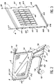
- a carriage 1 according to the invention shown in exploded view in Figure 1 includes the elements conventional components, such as a right sidewall 2, a left lateral flank 3, a front plate 4, a bottom 5, a back plate 6. Each lateral flank defines a side plate 7 and a foot segment 8.
- the cart basket 1 is bounded by the two plates 7, the front plate 4, the bottom 5 and the plate rear 6.
- Each side 2 or 3 still has a rim front 9, possibly a rear edge 10, and a edge bottom 11, flanges which are arranged so substantially perpendicular to the internal lateral surface of the corresponding flank.
- Each sidewall 1 or 2 is extended upwards and backwards by a tab 12, presenting a first housing 13 intended to receive an operating bar 14 and a second housing 15 intended to receive the means of liaison, described more fully below in relation to Figures 7 and 8.
- Each lateral flank 2 or 3 delimits as previously indicated a foot segment 8 consisting of walls 16, 17 and 18 which give it rigidity necessary to absorb shocks, and allow bending caused by the basket when it is loaded and for finally allow the nesting of the carriages one in the others when these are stored.
- the wall 16 has a inclination a of the order of 140 ° relative to the edge 10 and continuously extends the edge 11.
- the wall 18 delimits with the underside of the rim 11, to which it is connected, an open U. Radial ribs 19, 20, 21, 22 make it possible to stiffen the foot segment 8 to increase its resistance.
- the front edge 9 is provided a set of slots 23 and notches 24 substantially of the same length.
- the bottom edge 11 is also provided with slots 25 and notches 26 of substantially the same length.
- FIG. 3 shows a exemplary embodiment of the front plate 4 of the carriage according to the invention.
- slots 43 and notches 44 intended to cooperate respectively with the notches 24 and slots 23 of the edge 9 of the flanks side 2 and 3.
- This plate can be pierced with light 45.
- the lower edge 46 of the plate 4 has a slight rounded 47 and is provided with a groove 48 intended to receive the bottom edge 5 as will be explained below more in detail.
- each niche 43 has a hole 49, the holes of the different slots being aligned along the same generator. So is even slots 23 of edge 9 of side 2 or 3.
- the different slots are joined using the rods 50 and 51 thus constituting a solid assembly resistant to usual stresses to which the carriage is subjected.
- the backplane 5 shown in perspective in Figure 4 is a rectangular plate with a thickness about 10 to 20 mm of which the two lengths 60 and 61 are provided with slots 62 and notches 63 arranged symmetrically.
- the bottom can be fitted with lights 64 facilitating the possible flow of liquid.
- the edge front 65 is provided with a rebate 66 adapted to dimensions of the groove 48 of the plate 4.
- each slot of each length is provided with holes 67 of which the diameter is adapted to that of the rods 68 and 69.
- the edge posterior 70 from the bottom 5 is provided with two notches 71 and 72 intended to cooperate with lugs of the rear plate 6 as will be explained below. This rim 70 is extended by a lip 73 curved towards the bottom of the carriage.
- the foot segments 8 of the lateral flanks 2 and 3 are joined by the base 80 shown in Figure 5 which is in the general form of a plate 81 of 2 about 15 mm thick, terminated by two spouts 82 and 83 of opposite curvature.
- the spout 82 has a curvature, the concavity is directed upwards and is terminated by two mortises 84 and 85.
- Each mortise has a groove longitudinal 86 in which is engaged a rib of reinforcement of the corresponding post of the foot segment.
- the plate 81 can be provided with openings 87 and supports two 88 opposite mortises, only one of which is visible, combined between them and to the plate 81 by a transverse wall 89 in order to perfect its rigidity.
- the spout 83 has a concavity directed downwards and comprises two mortises 90, only one of which is visible, each connected at the end of this spout by a longitudinal wall 91.
- the back plate 6 shown in Figure 6 does not have slots or notches and does not participate in the rigidity of the cart basket. It is linked in a way rotatable to the fixing bar 120 described below in relationship with Figure 7.
- the upper edge 100 of plate 6 is provided with slots 101 alternating with notches 102.
- the slots and notches are arranged on either side of the part center of edge 100.
- Each slot has a hole 103, the set of holes being aligned along the same generator.
- Two rods 104 adapted to the diameter of the holes 103 allow to link on each side the plate 6 to the bar 120.
- Plate 6 has at its lower edge 105 two pins 106 and 107 arranged symmetrically by compared to the middle part which are intended to cooperate in stop respectively with the notches 71 and 72 of the plate bottom so as to limit its rearward travel.
- Figure 6 which illustrates an internal side view of basket also shows that the plate 6 is provided with a hook 108, two lights 109, 110, and means for fixing a retractable support plate, not shown, for example for baby, mounted in a known manner.
- These can be constituted by fixing lugs 111 and 112 receiving each a finger and a set of slots 113 and of notches 114. Each slot has a hole 115 in it, all the holes being arranged on a generator parallel to edge 110.
- Plate 6 can also include a number of lights 116.
- the fixing bar 120 shown in the Figure 7 allows to rigidly connect the two sides 2 and 3 at the level of the legs 12.
- the bar 120 is provided at each end of a pin 122 terminated by a flange 124.
- the bar is still provided with two sets 125 and 126 of two fingers 127 and 128 pierced with a hole 129, the whole holes 129 being aligned on the same generator and are each intended to receive a rod 104.
- the fingers 127, 128 are engaged in the notches 102 of the plate 6 according to Figure 6 to constitute the means of fixing of the plate 6 to the bar 120, while allowing its rotation relative to said bar.
- Figure 8 illustrates the method of linking maneuvering bars 14 and connecting bars 120 to lug 12 of each side 2 or 3.
- the tab 12 which extends each side includes a first bead 130 having the housing 15 the bottom of which is provided with a groove 131.
- the housing assembly 15 and groove 131 is intended to cooperate with respectively the pin 122 and the flange 124 of the bar 120.
- the tab 12 finally comprises a second bead 133 provided with the housing 13 intended to receive the bar 14 for maneuvering the carriage 1.
- the connection of the bar 120 with the tab 12 can be made inviolable by bringing the extreme slot 101 into abutment on the bead 130.
- Figure 9 illustrates the link mode of the plate 80 at foot segment 8.
- foot 8 is provided with a pin 134 connected to a rib 135 secured to the wall 17.
- This tenon 134 cooperates with the mortise 84 of the plate 80 for fixing the assembly.
- Others pins are of course intended to cooperate with different mortises 88 and 90 provided on each side of the plate 80.
- the assembly of the basket is completed by presenting the front plate 4 on the sides 2 and 3 so as to insert the slots 43 into the notches 24 of the sides, the slots 23 of each flank then being engaged in the notches 44 on the front plate and engaging the rebate 66 in the groove 48.
- the rods 50 and 51 are then introduced into the aligned holes 49 to secure the front plate with the sides.
- We finish assembling the carriage by mounting the connecting bar 120. For this, we engage the pins 122 in the housings 15 of each tab, the flange 124 being retained in the groove 131.
- the rear plate 6 is mounted by engaging the fingers 127 of the bar 120 in the notches 102, then by engaging on each side the rods 104 in the holes 103 provided for this purpose.
- the disassembly of the carriage becomes impossible. Indeed, the last slot 101 forms an obstacle to tearing off because it abuts against the bead 130.
- the rear plate 6 can therefore be folded towards the inside of the basket under the action of another cart to facilitate storage.
- the backward movement of the plate 6 is limited by the pins 106 and 107 which are engaged in abutment in the notches 71 and 72.
Landscapes
- Engineering & Computer Science (AREA)
- Chemical & Material Sciences (AREA)
- Combustion & Propulsion (AREA)
- Transportation (AREA)
- Mechanical Engineering (AREA)
- Handcart (AREA)
- Brushes (AREA)
- Walking Sticks, Umbrellas, And Fans (AREA)
- Separation Using Semi-Permeable Membranes (AREA)
- Suspension Of Electric Lines Or Cables (AREA)
- Processing And Handling Of Plastics And Other Materials For Molding In General (AREA)
- Separation, Recovery Or Treatment Of Waste Materials Containing Plastics (AREA)
Applications Claiming Priority (3)
| Application Number | Priority Date | Filing Date | Title |
|---|---|---|---|
| FR9309018A FR2707943B1 (fr) | 1993-07-22 | 1993-07-22 | Chariot en matière synthétique. |
| FR9309018 | 1993-07-22 | ||
| PCT/FR1994/000923 WO1995003201A1 (fr) | 1993-07-22 | 1994-07-22 | Chariot en matiere synthetique |
Publications (2)
| Publication Number | Publication Date |
|---|---|
| EP0708723A1 EP0708723A1 (fr) | 1996-05-01 |
| EP0708723B1 true EP0708723B1 (fr) | 1999-01-27 |
Family
ID=9449503
Family Applications (1)
| Application Number | Title | Priority Date | Filing Date |
|---|---|---|---|
| EP94922297A Expired - Lifetime EP0708723B1 (fr) | 1993-07-22 | 1994-07-22 | Chariot en matiere synthetique |
Country Status (12)
| Country | Link |
|---|---|
| EP (1) | EP0708723B1 (cs) |
| AT (1) | ATE176205T1 (cs) |
| AU (1) | AU7346894A (cs) |
| CA (1) | CA2166887A1 (cs) |
| CZ (1) | CZ283901B6 (cs) |
| DE (1) | DE69416310T2 (cs) |
| DK (1) | DK0708723T3 (cs) |
| ES (1) | ES2126767T3 (cs) |
| FR (1) | FR2707943B1 (cs) |
| GR (1) | GR3029801T3 (cs) |
| HU (1) | HU9600119D0 (cs) |
| WO (1) | WO1995003201A1 (cs) |
Families Citing this family (6)
| Publication number | Priority date | Publication date | Assignee | Title |
|---|---|---|---|---|
| DE29913434U1 (de) * | 1999-08-09 | 2000-12-28 | Siegel Geb Gmbh Co Kg | Stapelbarer Einkaufswagen |
| US6540240B2 (en) | 2000-07-12 | 2003-04-01 | Les Industries Rondi Inc. | Collapsible compartment for a shopping cart |
| CA2366158C (en) | 2001-12-21 | 2008-01-29 | Les Industries Rondi Inc. | Modular plastic shopping cart |
| USD530478S1 (en) | 2005-09-19 | 2006-10-17 | Target Brands, Inc. | Shopping cart |
| DE102006016386A1 (de) * | 2006-04-05 | 2007-10-11 | Wanzl Metallwarenfabrik Gmbh | Einkaufswagen |
| US11213616B2 (en) | 2018-08-24 | 2022-01-04 | Medtronic, Inc. | Recharge solution for zirconium phosphate |
Family Cites Families (3)
| Publication number | Priority date | Publication date | Assignee | Title |
|---|---|---|---|---|
| US4632411A (en) * | 1985-05-01 | 1986-12-30 | United Steel & Wire Company | Shopping cart with plastic basket |
| CA2048360A1 (en) * | 1991-08-02 | 1993-02-03 | Madj Silzer | Shopping cart |
| FR2684346A1 (fr) * | 1991-12-02 | 1993-06-04 | Paly Jean Luc | Procede de fabrication d'un chariot en matiere synthetique. |
-
1993
- 1993-07-22 FR FR9309018A patent/FR2707943B1/fr not_active Expired - Fee Related
-
1994
- 1994-07-22 CA CA002166887A patent/CA2166887A1/fr not_active Abandoned
- 1994-07-22 AT AT94922297T patent/ATE176205T1/de not_active IP Right Cessation
- 1994-07-22 DE DE69416310T patent/DE69416310T2/de not_active Expired - Fee Related
- 1994-07-22 CZ CZ96192A patent/CZ283901B6/cs not_active IP Right Cessation
- 1994-07-22 DK DK94922297T patent/DK0708723T3/da active
- 1994-07-22 WO PCT/FR1994/000923 patent/WO1995003201A1/fr active IP Right Grant
- 1994-07-22 ES ES94922297T patent/ES2126767T3/es not_active Expired - Lifetime
- 1994-07-22 EP EP94922297A patent/EP0708723B1/fr not_active Expired - Lifetime
- 1994-07-22 AU AU73468/94A patent/AU7346894A/en not_active Abandoned
- 1994-07-22 HU HU9600119A patent/HU9600119D0/hu unknown
-
1999
- 1999-03-26 GR GR990400890T patent/GR3029801T3/el unknown
Also Published As
| Publication number | Publication date |
|---|---|
| CZ19296A3 (en) | 1996-06-12 |
| ATE176205T1 (de) | 1999-02-15 |
| EP0708723A1 (fr) | 1996-05-01 |
| CA2166887A1 (fr) | 1995-02-02 |
| ES2126767T3 (es) | 1999-04-01 |
| FR2707943B1 (fr) | 1995-09-15 |
| FR2707943A1 (fr) | 1995-01-27 |
| DE69416310T2 (de) | 1999-06-02 |
| CZ283901B6 (cs) | 1998-07-15 |
| WO1995003201A1 (fr) | 1995-02-02 |
| DK0708723T3 (da) | 1999-09-13 |
| AU7346894A (en) | 1995-02-20 |
| DE69416310D1 (de) | 1999-03-11 |
| HU9600119D0 (en) | 1996-03-28 |
| GR3029801T3 (en) | 1999-06-30 |
Similar Documents
| Publication | Publication Date | Title |
|---|---|---|
| EP0226505B1 (fr) | Palette de chargement renforcée et procédé de renforcement d'une telle palette | |
| FR2533123A1 (fr) | Dispositif formant ossature notamment pour meuble de rangement, par exemple un rayonnage | |
| EP0614429B1 (fr) | Procede de fabrication d'un chariot en matiere synthetique | |
| FR2519928A1 (fr) | Vehicule a carenage de tete de fourche pourvu d'un bac de rangement | |
| WO1999043532A1 (fr) | Vehicule de deplacement pour enfant en bas age | |
| FR2622813A1 (fr) | Voiture-jouet transformable avec accessoires enfichables | |
| EP2247488B1 (fr) | Console pour l'equipement d'un chariot roulant, notamment de supermarche | |
| BE1006672A3 (fr) | Cadre de cycle. | |
| EP0708723B1 (fr) | Chariot en matiere synthetique | |
| EP0320318B1 (fr) | Chariot grillagé susceptible de résister aux chocs et destiné au transport de produits divers | |
| FR2685875A3 (en) | Structure for mounting a golf-trolley wheel frame | |
| FR2473895A1 (fr) | Vehicule-jouet convertible a transporter des charges-a chevaucher | |
| EP0629539A1 (fr) | Véhicule du type poussette | |
| FR2955314A1 (fr) | Conteneur demontable, de type notamment bac a plantes | |
| EP0908373A1 (fr) | Dispositif de fixation d'une façade avant à la structure avant d'un véhicule automobile | |
| FR2556680A1 (fr) | Poussette pliante | |
| FR2770479A1 (fr) | Chariot pliable | |
| EP4223185A1 (fr) | Chaise empilable et assemblable en rangee | |
| EP0399894A1 (fr) | Meuble en matière plastique pour s'asseoir | |
| FR2583367A1 (fr) | Bicyclette de transport | |
| FR2826896A1 (fr) | Chariot de rangement notamment d'outils, a structure amelioree | |
| FR3100698A1 (fr) | Article de puériculture, adapté à recevoir un enfant | |
| EP1029766A1 (fr) | Chariot emboítable notamment adapté à reçevoir des objets volumineux | |
| LU84799A1 (fr) | Structure de chassis porteur pour chariots et similaires | |
| FR2481217A1 (fr) | Chariot de manutention repliable, destine a contenir des objets divers |
Legal Events
| Date | Code | Title | Description |
|---|---|---|---|
| PUAI | Public reference made under article 153(3) epc to a published international application that has entered the european phase |
Free format text: ORIGINAL CODE: 0009012 |
|
| 17P | Request for examination filed |
Effective date: 19960122 |
|
| AK | Designated contracting states |
Kind code of ref document: A1 Designated state(s): AT BE CH DE DK ES FR GB GR IE IT LI LU MC NL PT SE |
|
| 18D | Application deemed to be withdrawn |
Effective date: 19970201 |
|
| 18RA | Request filed for re-establishment of rights before grant |
Effective date: 19970715 |
|
| 18RR | Decision to grant the request for re-establishment of rights before grant |
Free format text: 980113 ANGENOMMEN |
|
| 17Q | First examination report despatched |
Effective date: 19980123 |
|
| REG | Reference to a national code |
Ref country code: DE Ref legal event code: 8570 |
|
| GRAG | Despatch of communication of intention to grant |
Free format text: ORIGINAL CODE: EPIDOS AGRA |
|
| GRAG | Despatch of communication of intention to grant |
Free format text: ORIGINAL CODE: EPIDOS AGRA |
|
| GRAH | Despatch of communication of intention to grant a patent |
Free format text: ORIGINAL CODE: EPIDOS IGRA |
|
| D18D | Application deemed to be withdrawn (deleted) | ||
| GRAH | Despatch of communication of intention to grant a patent |
Free format text: ORIGINAL CODE: EPIDOS IGRA |
|
| GRAA | (expected) grant |
Free format text: ORIGINAL CODE: 0009210 |
|
| AK | Designated contracting states |
Kind code of ref document: B1 Designated state(s): AT BE CH DE DK ES FR GB GR IE IT LI LU MC NL PT SE |
|
| REF | Corresponds to: |
Ref document number: 176205 Country of ref document: AT Date of ref document: 19990215 Kind code of ref document: T |
|
| REG | Reference to a national code |
Ref country code: CH Ref legal event code: EP |
|
| ITF | It: translation for a ep patent filed |
Owner name: BARZANO' E ZANARDO MILANO S.P.A. |
|
| GBT | Gb: translation of ep patent filed (gb section 77(6)(a)/1977) |
Effective date: 19990209 |
|
| REG | Reference to a national code |
Ref country code: IE Ref legal event code: FG4D Free format text: FRENCH |
|
| REF | Corresponds to: |
Ref document number: 69416310 Country of ref document: DE Date of ref document: 19990311 |
|
| REG | Reference to a national code |
Ref country code: CH Ref legal event code: NV Representative=s name: DIPL.-ING. ETH H. R. WERFFELI PATENTANWALT |
|
| REG | Reference to a national code |
Ref country code: ES Ref legal event code: FG2A Ref document number: 2126767 Country of ref document: ES Kind code of ref document: T3 |
|
| REG | Reference to a national code |
Ref country code: PT Ref legal event code: SC4A Free format text: AVAILABILITY OF NATIONAL TRANSLATION Effective date: 19990215 |
|
| PGFP | Annual fee paid to national office [announced via postgrant information from national office to epo] |
Ref country code: DK Payment date: 19990618 Year of fee payment: 6 |
|
| PGFP | Annual fee paid to national office [announced via postgrant information from national office to epo] |
Ref country code: AT Payment date: 19990621 Year of fee payment: 6 |
|
| PGFP | Annual fee paid to national office [announced via postgrant information from national office to epo] |
Ref country code: CH Payment date: 19990624 Year of fee payment: 6 |
|
| PGFP | Annual fee paid to national office [announced via postgrant information from national office to epo] |
Ref country code: LU Payment date: 19990625 Year of fee payment: 6 Ref country code: GB Payment date: 19990625 Year of fee payment: 6 |
|
| PGFP | Annual fee paid to national office [announced via postgrant information from national office to epo] |
Ref country code: MC Payment date: 19990626 Year of fee payment: 6 |
|
| PGFP | Annual fee paid to national office [announced via postgrant information from national office to epo] |
Ref country code: SE Payment date: 19990628 Year of fee payment: 6 Ref country code: IE Payment date: 19990628 Year of fee payment: 6 Ref country code: DE Payment date: 19990628 Year of fee payment: 6 |
|
| PGFP | Annual fee paid to national office [announced via postgrant information from national office to epo] |
Ref country code: GR Payment date: 19990629 Year of fee payment: 6 |
|
| PGFP | Annual fee paid to national office [announced via postgrant information from national office to epo] |
Ref country code: NL Payment date: 19990630 Year of fee payment: 6 |
|
| PGFP | Annual fee paid to national office [announced via postgrant information from national office to epo] |
Ref country code: PT Payment date: 19990705 Year of fee payment: 6 |
|
| PGFP | Annual fee paid to national office [announced via postgrant information from national office to epo] |
Ref country code: ES Payment date: 19990716 Year of fee payment: 6 Ref country code: BE Payment date: 19990716 Year of fee payment: 6 |
|
| PGFP | Annual fee paid to national office [announced via postgrant information from national office to epo] |
Ref country code: FR Payment date: 19990730 Year of fee payment: 6 |
|
| REG | Reference to a national code |
Ref country code: DK Ref legal event code: T3 |
|
| PLBE | No opposition filed within time limit |
Free format text: ORIGINAL CODE: 0009261 |
|
| STAA | Information on the status of an ep patent application or granted ep patent |
Free format text: STATUS: NO OPPOSITION FILED WITHIN TIME LIMIT |
|
| 26N | No opposition filed | ||
| PG25 | Lapsed in a contracting state [announced via postgrant information from national office to epo] |
Ref country code: LU Free format text: LAPSE BECAUSE OF NON-PAYMENT OF DUE FEES Effective date: 20000722 Ref country code: IE Free format text: LAPSE BECAUSE OF NON-PAYMENT OF DUE FEES Effective date: 20000722 Ref country code: GB Free format text: LAPSE BECAUSE OF NON-PAYMENT OF DUE FEES Effective date: 20000722 Ref country code: DK Free format text: LAPSE BECAUSE OF NON-PAYMENT OF DUE FEES Effective date: 20000722 Ref country code: AT Free format text: LAPSE BECAUSE OF NON-PAYMENT OF DUE FEES Effective date: 20000722 |
|
| PG25 | Lapsed in a contracting state [announced via postgrant information from national office to epo] |
Ref country code: SE Free format text: LAPSE BECAUSE OF NON-PAYMENT OF DUE FEES Effective date: 20000723 Ref country code: ES Free format text: LAPSE BECAUSE OF NON-PAYMENT OF DUE FEES Effective date: 20000723 |
|
| PG25 | Lapsed in a contracting state [announced via postgrant information from national office to epo] |
Ref country code: MC Free format text: THE PATENT HAS BEEN ANNULLED BY A DECISION OF A NATIONAL AUTHORITY Effective date: 20000731 Ref country code: LI Free format text: LAPSE BECAUSE OF NON-PAYMENT OF DUE FEES Effective date: 20000731 Ref country code: GR Free format text: LAPSE BECAUSE OF NON-PAYMENT OF DUE FEES Effective date: 20000731 Ref country code: CH Free format text: LAPSE BECAUSE OF NON-PAYMENT OF DUE FEES Effective date: 20000731 Ref country code: BE Free format text: LAPSE BECAUSE OF NON-PAYMENT OF DUE FEES Effective date: 20000731 |
|
| BERE | Be: lapsed |
Owner name: ICD HOLDING B.V. Effective date: 20000731 Owner name: GIAT INDUSTRIES Effective date: 20000731 |
|
| PG25 | Lapsed in a contracting state [announced via postgrant information from national office to epo] |
Ref country code: PT Free format text: LAPSE BECAUSE OF NON-PAYMENT OF DUE FEES Effective date: 20010131 |
|
| PG25 | Lapsed in a contracting state [announced via postgrant information from national office to epo] |
Ref country code: NL Free format text: LAPSE BECAUSE OF NON-PAYMENT OF DUE FEES Effective date: 20010201 |
|
| REG | Reference to a national code |
Ref country code: DK Ref legal event code: EBP |
|
| GBPC | Gb: european patent ceased through non-payment of renewal fee |
Effective date: 20000722 |
|
| REG | Reference to a national code |
Ref country code: CH Ref legal event code: PL |
|
| EUG | Se: european patent has lapsed |
Ref document number: 94922297.0 |
|
| PG25 | Lapsed in a contracting state [announced via postgrant information from national office to epo] |
Ref country code: FR Free format text: LAPSE BECAUSE OF NON-PAYMENT OF DUE FEES Effective date: 20010330 |
|
| NLV4 | Nl: lapsed or anulled due to non-payment of the annual fee |
Effective date: 20010201 |
|
| REG | Reference to a national code |
Ref country code: FR Ref legal event code: ST |
|
| PG25 | Lapsed in a contracting state [announced via postgrant information from national office to epo] |
Ref country code: DE Free format text: LAPSE BECAUSE OF NON-PAYMENT OF DUE FEES Effective date: 20010501 |
|
| REG | Reference to a national code |
Ref country code: IE Ref legal event code: MM4A |
|
| REG | Reference to a national code |
Ref country code: PT Ref legal event code: MM4A Free format text: LAPSE DUE TO NON-PAYMENT OF FEES Effective date: 20010131 |
|
| REG | Reference to a national code |
Ref country code: ES Ref legal event code: FD2A Effective date: 20010810 |
|
| PG25 | Lapsed in a contracting state [announced via postgrant information from national office to epo] |
Ref country code: IT Free format text: LAPSE BECAUSE OF NON-PAYMENT OF DUE FEES Effective date: 20050722 |