EP0708293A2 - Vorrichtung zur Entnahme von kryogener Flüssigkeit - Google Patents
Vorrichtung zur Entnahme von kryogener Flüssigkeit Download PDFInfo
- Publication number
- EP0708293A2 EP0708293A2 EP95307074A EP95307074A EP0708293A2 EP 0708293 A2 EP0708293 A2 EP 0708293A2 EP 95307074 A EP95307074 A EP 95307074A EP 95307074 A EP95307074 A EP 95307074A EP 0708293 A2 EP0708293 A2 EP 0708293A2
- Authority
- EP
- European Patent Office
- Prior art keywords
- dewar
- withdrawal
- liquid
- plug
- withdrawal device
- Prior art date
- Legal status (The legal status is an assumption and is not a legal conclusion. Google has not performed a legal analysis and makes no representation as to the accuracy of the status listed.)
- Ceased
Links
- 239000007788 liquid Substances 0.000 title claims abstract description 61
- 229910000906 Bronze Inorganic materials 0.000 claims abstract description 11
- 239000010974 bronze Substances 0.000 claims abstract description 11
- KUNSUQLRTQLHQQ-UHFFFAOYSA-N copper tin Chemical compound [Cu].[Sn] KUNSUQLRTQLHQQ-UHFFFAOYSA-N 0.000 claims abstract description 11
- 238000003780 insertion Methods 0.000 claims abstract 2
- 230000037431 insertion Effects 0.000 claims abstract 2
- IJGRMHOSHXDMSA-UHFFFAOYSA-N Atomic nitrogen Chemical compound N#N IJGRMHOSHXDMSA-UHFFFAOYSA-N 0.000 claims description 24
- 239000007789 gas Substances 0.000 claims description 14
- 229910052757 nitrogen Inorganic materials 0.000 claims description 12
- 238000000034 method Methods 0.000 claims description 4
- 238000004891 communication Methods 0.000 claims description 2
- 239000011810 insulating material Substances 0.000 claims 1
- 238000009835 boiling Methods 0.000 abstract description 4
- 229910001369 Brass Inorganic materials 0.000 description 11
- 239000010951 brass Substances 0.000 description 11
- 238000001704 evaporation Methods 0.000 description 5
- 230000008020 evaporation Effects 0.000 description 5
- 239000000463 material Substances 0.000 description 5
- 230000003068 static effect Effects 0.000 description 5
- 229910001220 stainless steel Inorganic materials 0.000 description 4
- 239000010935 stainless steel Substances 0.000 description 4
- BQCADISMDOOEFD-UHFFFAOYSA-N Silver Chemical compound [Ag] BQCADISMDOOEFD-UHFFFAOYSA-N 0.000 description 3
- 238000009413 insulation Methods 0.000 description 3
- 229910052709 silver Inorganic materials 0.000 description 3
- 239000004332 silver Substances 0.000 description 3
- 229920001296 polysiloxane Polymers 0.000 description 2
- 239000010963 304 stainless steel Substances 0.000 description 1
- 229920004943 Delrin® Polymers 0.000 description 1
- 229910000589 SAE 304 stainless steel Inorganic materials 0.000 description 1
- 238000007792 addition Methods 0.000 description 1
- 238000005276 aerator Methods 0.000 description 1
- 239000004411 aluminium Substances 0.000 description 1
- 229910052782 aluminium Inorganic materials 0.000 description 1
- XAGFODPZIPBFFR-UHFFFAOYSA-N aluminium Chemical compound [Al] XAGFODPZIPBFFR-UHFFFAOYSA-N 0.000 description 1
- 239000007799 cork Substances 0.000 description 1
- 239000003317 industrial substance Substances 0.000 description 1
- 239000002184 metal Substances 0.000 description 1
- 229910052751 metal Inorganic materials 0.000 description 1
- 230000002093 peripheral effect Effects 0.000 description 1
- 238000005086 pumping Methods 0.000 description 1
- 230000001105 regulatory effect Effects 0.000 description 1
Images

Classifications
-
- F—MECHANICAL ENGINEERING; LIGHTING; HEATING; WEAPONS; BLASTING
- F17—STORING OR DISTRIBUTING GASES OR LIQUIDS
- F17C—VESSELS FOR CONTAINING OR STORING COMPRESSED, LIQUEFIED OR SOLIDIFIED GASES; FIXED-CAPACITY GAS-HOLDERS; FILLING VESSELS WITH, OR DISCHARGING FROM VESSELS, COMPRESSED, LIQUEFIED, OR SOLIDIFIED GASES
- F17C7/00—Methods or apparatus for discharging liquefied, solidified, or compressed gases from pressure vessels, not covered by another subclass
- F17C7/02—Discharging liquefied gases
-
- F—MECHANICAL ENGINEERING; LIGHTING; HEATING; WEAPONS; BLASTING
- F17—STORING OR DISTRIBUTING GASES OR LIQUIDS
- F17C—VESSELS FOR CONTAINING OR STORING COMPRESSED, LIQUEFIED OR SOLIDIFIED GASES; FIXED-CAPACITY GAS-HOLDERS; FILLING VESSELS WITH, OR DISCHARGING FROM VESSELS, COMPRESSED, LIQUEFIED, OR SOLIDIFIED GASES
- F17C2201/00—Vessel construction, in particular geometry, arrangement or size
- F17C2201/01—Shape
- F17C2201/0104—Shape cylindrical
- F17C2201/0109—Shape cylindrical with exteriorly curved end-piece
-
- F—MECHANICAL ENGINEERING; LIGHTING; HEATING; WEAPONS; BLASTING
- F17—STORING OR DISTRIBUTING GASES OR LIQUIDS
- F17C—VESSELS FOR CONTAINING OR STORING COMPRESSED, LIQUEFIED OR SOLIDIFIED GASES; FIXED-CAPACITY GAS-HOLDERS; FILLING VESSELS WITH, OR DISCHARGING FROM VESSELS, COMPRESSED, LIQUEFIED, OR SOLIDIFIED GASES
- F17C2201/00—Vessel construction, in particular geometry, arrangement or size
- F17C2201/01—Shape
- F17C2201/0104—Shape cylindrical
- F17C2201/0119—Shape cylindrical with flat end-piece
-
- F—MECHANICAL ENGINEERING; LIGHTING; HEATING; WEAPONS; BLASTING
- F17—STORING OR DISTRIBUTING GASES OR LIQUIDS
- F17C—VESSELS FOR CONTAINING OR STORING COMPRESSED, LIQUEFIED OR SOLIDIFIED GASES; FIXED-CAPACITY GAS-HOLDERS; FILLING VESSELS WITH, OR DISCHARGING FROM VESSELS, COMPRESSED, LIQUEFIED, OR SOLIDIFIED GASES
- F17C2201/00—Vessel construction, in particular geometry, arrangement or size
- F17C2201/03—Orientation
- F17C2201/032—Orientation with substantially vertical main axis
-
- F—MECHANICAL ENGINEERING; LIGHTING; HEATING; WEAPONS; BLASTING
- F17—STORING OR DISTRIBUTING GASES OR LIQUIDS
- F17C—VESSELS FOR CONTAINING OR STORING COMPRESSED, LIQUEFIED OR SOLIDIFIED GASES; FIXED-CAPACITY GAS-HOLDERS; FILLING VESSELS WITH, OR DISCHARGING FROM VESSELS, COMPRESSED, LIQUEFIED, OR SOLIDIFIED GASES
- F17C2201/00—Vessel construction, in particular geometry, arrangement or size
- F17C2201/05—Size
- F17C2201/058—Size portable (<30 l)
-
- F—MECHANICAL ENGINEERING; LIGHTING; HEATING; WEAPONS; BLASTING
- F17—STORING OR DISTRIBUTING GASES OR LIQUIDS
- F17C—VESSELS FOR CONTAINING OR STORING COMPRESSED, LIQUEFIED OR SOLIDIFIED GASES; FIXED-CAPACITY GAS-HOLDERS; FILLING VESSELS WITH, OR DISCHARGING FROM VESSELS, COMPRESSED, LIQUEFIED, OR SOLIDIFIED GASES
- F17C2203/00—Vessel construction, in particular walls or details thereof
- F17C2203/06—Materials for walls or layers thereof; Properties or structures of walls or their materials
- F17C2203/0602—Wall structures; Special features thereof
- F17C2203/0612—Wall structures
- F17C2203/0626—Multiple walls
- F17C2203/0629—Two walls
-
- F—MECHANICAL ENGINEERING; LIGHTING; HEATING; WEAPONS; BLASTING
- F17—STORING OR DISTRIBUTING GASES OR LIQUIDS
- F17C—VESSELS FOR CONTAINING OR STORING COMPRESSED, LIQUEFIED OR SOLIDIFIED GASES; FIXED-CAPACITY GAS-HOLDERS; FILLING VESSELS WITH, OR DISCHARGING FROM VESSELS, COMPRESSED, LIQUEFIED, OR SOLIDIFIED GASES
- F17C2203/00—Vessel construction, in particular walls or details thereof
- F17C2203/06—Materials for walls or layers thereof; Properties or structures of walls or their materials
- F17C2203/0634—Materials for walls or layers thereof
- F17C2203/0636—Metals
- F17C2203/0639—Steels
- F17C2203/0643—Stainless steels
-
- F—MECHANICAL ENGINEERING; LIGHTING; HEATING; WEAPONS; BLASTING
- F17—STORING OR DISTRIBUTING GASES OR LIQUIDS
- F17C—VESSELS FOR CONTAINING OR STORING COMPRESSED, LIQUEFIED OR SOLIDIFIED GASES; FIXED-CAPACITY GAS-HOLDERS; FILLING VESSELS WITH, OR DISCHARGING FROM VESSELS, COMPRESSED, LIQUEFIED, OR SOLIDIFIED GASES
- F17C2203/00—Vessel construction, in particular walls or details thereof
- F17C2203/06—Materials for walls or layers thereof; Properties or structures of walls or their materials
- F17C2203/0634—Materials for walls or layers thereof
- F17C2203/0636—Metals
- F17C2203/0646—Aluminium
-
- F—MECHANICAL ENGINEERING; LIGHTING; HEATING; WEAPONS; BLASTING
- F17—STORING OR DISTRIBUTING GASES OR LIQUIDS
- F17C—VESSELS FOR CONTAINING OR STORING COMPRESSED, LIQUEFIED OR SOLIDIFIED GASES; FIXED-CAPACITY GAS-HOLDERS; FILLING VESSELS WITH, OR DISCHARGING FROM VESSELS, COMPRESSED, LIQUEFIED, OR SOLIDIFIED GASES
- F17C2205/00—Vessel construction, in particular mounting arrangements, attachments or identifications means
- F17C2205/01—Mounting arrangements
- F17C2205/0153—Details of mounting arrangements
- F17C2205/0157—Details of mounting arrangements for transport
- F17C2205/0165—Details of mounting arrangements for transport with handgrip
-
- F—MECHANICAL ENGINEERING; LIGHTING; HEATING; WEAPONS; BLASTING
- F17—STORING OR DISTRIBUTING GASES OR LIQUIDS
- F17C—VESSELS FOR CONTAINING OR STORING COMPRESSED, LIQUEFIED OR SOLIDIFIED GASES; FIXED-CAPACITY GAS-HOLDERS; FILLING VESSELS WITH, OR DISCHARGING FROM VESSELS, COMPRESSED, LIQUEFIED, OR SOLIDIFIED GASES
- F17C2205/00—Vessel construction, in particular mounting arrangements, attachments or identifications means
- F17C2205/03—Fluid connections, filters, valves, closure means or other attachments
- F17C2205/0302—Fittings, valves, filters, or components in connection with the gas storage device
- F17C2205/0323—Valves
- F17C2205/0332—Safety valves or pressure relief valves
-
- F—MECHANICAL ENGINEERING; LIGHTING; HEATING; WEAPONS; BLASTING
- F17—STORING OR DISTRIBUTING GASES OR LIQUIDS
- F17C—VESSELS FOR CONTAINING OR STORING COMPRESSED, LIQUEFIED OR SOLIDIFIED GASES; FIXED-CAPACITY GAS-HOLDERS; FILLING VESSELS WITH, OR DISCHARGING FROM VESSELS, COMPRESSED, LIQUEFIED, OR SOLIDIFIED GASES
- F17C2205/00—Vessel construction, in particular mounting arrangements, attachments or identifications means
- F17C2205/03—Fluid connections, filters, valves, closure means or other attachments
- F17C2205/0302—Fittings, valves, filters, or components in connection with the gas storage device
- F17C2205/0341—Filters
- F17C2205/0344—Sinter type
-
- F—MECHANICAL ENGINEERING; LIGHTING; HEATING; WEAPONS; BLASTING
- F17—STORING OR DISTRIBUTING GASES OR LIQUIDS
- F17C—VESSELS FOR CONTAINING OR STORING COMPRESSED, LIQUEFIED OR SOLIDIFIED GASES; FIXED-CAPACITY GAS-HOLDERS; FILLING VESSELS WITH, OR DISCHARGING FROM VESSELS, COMPRESSED, LIQUEFIED, OR SOLIDIFIED GASES
- F17C2221/00—Handled fluid, in particular type of fluid
- F17C2221/01—Pure fluids
- F17C2221/014—Nitrogen
-
- F—MECHANICAL ENGINEERING; LIGHTING; HEATING; WEAPONS; BLASTING
- F17—STORING OR DISTRIBUTING GASES OR LIQUIDS
- F17C—VESSELS FOR CONTAINING OR STORING COMPRESSED, LIQUEFIED OR SOLIDIFIED GASES; FIXED-CAPACITY GAS-HOLDERS; FILLING VESSELS WITH, OR DISCHARGING FROM VESSELS, COMPRESSED, LIQUEFIED, OR SOLIDIFIED GASES
- F17C2223/00—Handled fluid before transfer, i.e. state of fluid when stored in the vessel or before transfer from the vessel
- F17C2223/01—Handled fluid before transfer, i.e. state of fluid when stored in the vessel or before transfer from the vessel characterised by the phase
- F17C2223/0146—Two-phase
- F17C2223/0153—Liquefied gas, e.g. LPG, GPL
- F17C2223/0161—Liquefied gas, e.g. LPG, GPL cryogenic, e.g. LNG, GNL, PLNG
-
- F—MECHANICAL ENGINEERING; LIGHTING; HEATING; WEAPONS; BLASTING
- F17—STORING OR DISTRIBUTING GASES OR LIQUIDS
- F17C—VESSELS FOR CONTAINING OR STORING COMPRESSED, LIQUEFIED OR SOLIDIFIED GASES; FIXED-CAPACITY GAS-HOLDERS; FILLING VESSELS WITH, OR DISCHARGING FROM VESSELS, COMPRESSED, LIQUEFIED, OR SOLIDIFIED GASES
- F17C2223/00—Handled fluid before transfer, i.e. state of fluid when stored in the vessel or before transfer from the vessel
- F17C2223/04—Handled fluid before transfer, i.e. state of fluid when stored in the vessel or before transfer from the vessel characterised by other properties of handled fluid before transfer
- F17C2223/042—Localisation of the removal point
- F17C2223/046—Localisation of the removal point in the liquid
- F17C2223/047—Localisation of the removal point in the liquid with a dip tube
-
- F—MECHANICAL ENGINEERING; LIGHTING; HEATING; WEAPONS; BLASTING
- F17—STORING OR DISTRIBUTING GASES OR LIQUIDS
- F17C—VESSELS FOR CONTAINING OR STORING COMPRESSED, LIQUEFIED OR SOLIDIFIED GASES; FIXED-CAPACITY GAS-HOLDERS; FILLING VESSELS WITH, OR DISCHARGING FROM VESSELS, COMPRESSED, LIQUEFIED, OR SOLIDIFIED GASES
- F17C2227/00—Transfer of fluids, i.e. method or means for transferring the fluid; Heat exchange with the fluid
- F17C2227/01—Propulsion of the fluid
- F17C2227/0107—Propulsion of the fluid by pressurising the ullage
-
- F—MECHANICAL ENGINEERING; LIGHTING; HEATING; WEAPONS; BLASTING
- F17—STORING OR DISTRIBUTING GASES OR LIQUIDS
- F17C—VESSELS FOR CONTAINING OR STORING COMPRESSED, LIQUEFIED OR SOLIDIFIED GASES; FIXED-CAPACITY GAS-HOLDERS; FILLING VESSELS WITH, OR DISCHARGING FROM VESSELS, COMPRESSED, LIQUEFIED, OR SOLIDIFIED GASES
- F17C2270/00—Applications
- F17C2270/02—Applications for medical applications
-
- F—MECHANICAL ENGINEERING; LIGHTING; HEATING; WEAPONS; BLASTING
- F17—STORING OR DISTRIBUTING GASES OR LIQUIDS
- F17C—VESSELS FOR CONTAINING OR STORING COMPRESSED, LIQUEFIED OR SOLIDIFIED GASES; FIXED-CAPACITY GAS-HOLDERS; FILLING VESSELS WITH, OR DISCHARGING FROM VESSELS, COMPRESSED, LIQUEFIED, OR SOLIDIFIED GASES
- F17C2270/00—Applications
- F17C2270/05—Applications for industrial use
- F17C2270/0509—"Dewar" vessels
Definitions
- This invention relates to a device for withdrawing liquified cryogenic gas, such as nitrogen, from a dewar, and related method, which essentially doubles the static holding time for cryogenic liquid stored in a dewar.
- liquified cryogenic gas such as nitrogen
- liquified nitrogen is typical of cryogens, and is widely used in industry and in health care.
- liquid nitrogen is stored in various sized dewars near the point of use, and smaller amounts are withdrawn from the dewar to be utilized in an apparatus or instrument as needed.
- An example of use in health care is set forth in U.S. Patent No. 4,116,199.
- Examples of the use of small amounts of nitrogen in industry are given in U.S. Patent No. 5,222,999 and U.S. Patent No. 5,237,836.
- nitrogen may be stored near an industrial work station or within a doctor's office or other treatment facility in a dewar ranging from 5 liters to 50 liters, depending upon the particular application involved.
- the nitrogen is withdrawn from the storage dewar and placed in the container of a utilization device, such as the examples referred to hereinbefore.
- the liquid cryogen is withdrawn from a storage dewar by means of what is known in the art as a withdrawal device.
- This constitutes a plug which fits into the top of the dewar in place of the storage plug, and is held tightly in place by means of expansion, or by means of hold-down devices, such as springs, straps or clamps.
- a common pressure relief valve which typically is set to maintain the gas pressure in the dewar no greater than about 4 pounds per square inch (28KPa).
- the device has a long tube which extends downwardly through the plug to the bottom of the dewar. It extends outwardly of the plug and turns to become horizontal, where a gas-tight valve is fitted.
- the tube may be bent downwardly somewhat to direct the liquid toward a container to be held near the dewar, and the liquid flows out of the tube through a sintered bronze filter, which softens the flow (much like the aerator on a kitchen faucet).
- the valve is opened; when the container (e.g., of the utilization device) is full, the valve is closed once again.
- the withdrawal unit remains attached to the dewar, immersed in the cryogen, at all times except when the dewar is being refilled.
- the principal problem with such a withdrawal device is that the presence of the tube within the liquid inside the storage dewar continuously pumps heat from the atmosphere outside into the liquid, causing it to continuously boil, converting the liquid to gas, which escapes through the pressure valve.
- a typical rate of evaporation is over twelve grams per hour (the density is about 816 grams per liter).
- a typical 10 liter dewar with a withdrawal device known in the art mounted therein has a static holding time (that is, the time when all 10 liters of cryogen will evaporate simply by sitting in the storage dewar, with no liquid being removed) of approximately 27 days. This means, in use, various amounts of the liquid are wasted, depending upon how much is actually used. While nitrogen is extremely inexpensive (compared to other industrial substances and medical modalities), the delivery of a small amount to a doctor's office, or the like, can be unnecessarily expensive, due to the evaporation caused by the withdrawal device.
- Objects of the invention include provision of a withdrawal device for liquid cryogen storage dewars and a method of use which minimizes the wasteful evaporation of the liquified cryogen, and a liquid cryogen withdrawal device which is safer to use than those known to the art.
- a device for withdrawing liquid cryogen from a cryogen storage dewar comprises an open tube, which may be fitted with the sintered bronze filter at a distal, outflow end thereof, and having a passive heat source disposed at a proximal, inflow end thereof, the tube being disposed through a plug that will fit in gas-tight relationship within the neck of a storage dewar.
- a valve on the device of the present invention.
- the liquid cryogen is stored in the dewar with its normal, loose fitting cap that allows the gas to escape around the loose fitting cap.
- the liquid lies quiescently, with a minimum of boiling and gas loss.
- the passive heat source transfers sufficient heat into the liquid cryogen so as to initially cause sufficient boiling to pressurize the dewar, thereby forcing liquid upwardly through the tube and the sintered bronze filter, where it can be captured in the utilizing device or other container.
- the passive heat source typically comprises a metal having a high heat capacity, such as brass, which may surround the base of the tubing. By regulating the amount of material in the passive heat source, a limited amount of control can be exercised over the flow of liquid.
- An insulated handle may be provided.
- the withdrawal device of the present invention may literally double the static holding time of liquid cryogen, such as nitrogen, reducing the evaporation to less than six grams per hour.
- liquid cryogen such as nitrogen
- use of the invention can increase the time for natural evaporation of a full dewar, such as 10 liters, to about 60 days.
- the invention also regulates the total flow from the device, since exhaustion of the heat provided by the tubing and the passive heat source results in the exhaustion of pressure, and a reduction of flow of liquid to a negligible amount (essentially zero).
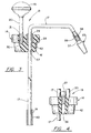
- Fig. 1 is a simplified front side elevation view of a dewar fitted with a withdrawal device according to the present invention.
- Fig. 2 is a top plan view of a plug which forms the basic structure of the withdrawal device of Fig. 1.
- Fig. 3 is a partial, partially broken away, front elevation view, partially sectioned on the line 3-3 of Fig. 2.
- Fig. 4 is a partial, rear elevation view of the plug, partially sectioned on the line 4-4 of Fig. 2.
- a dewar 10 typically comprises two aluminium (or stainless steel) containers, one disposed within the other, joined at a neck section 11, with the space therebetween evacuated so as to provide superior insulation.
- the dewar 10 may be provided with one or more handles 12.
- a withdrawal device 13 of the present invention includes a plug 14 which fits in gas-tight relationship within the opening of the neck 11.
- a withdrawal tube 17 extends through the plug 14 to the bottom of the interior of the dewar so as to convey liquid 22 from the dewar through a sintered bronze filter 23 and into any container which is held beneath the filter 23, much as a prior utilization device of the type described hereinbefore.
- a passive heat source 18 Surrounding the bottom, proximal end of the withdrawal tube 17 is a passive heat source 18 which, in this example, comprises a hollow cylinder of brass.
- the plug 14 has a handle 19 secured thereto by a shaft 20.
- the pressure in the dewar 10 is limited by virtue of a gas pressure relief valve 21 disposed on the plug 14 and in communication with the interior of the dewar 10.
- the withdrawal device 13 When liquified cryogen is being stored within the dewar 10, in accordance with the invention, the withdrawal device 13 is not installed in the dewar as shown in Fig. l. Instead, a loosely fitting cap (not shown), which is common in the art, similar to the plug 14, provides insulation but allows gas to freely escape. Thus, there is no heat conducted into the liquid 22 within the dewar, so the liquid boils much less than it would with withdrawal devices known to the prior art installed in the dewar 10. Therefore, the static holding time is approximately doubled.
- the loose cap (not shown hereinbefore) is removed from the dewar 10, and the withdrawal device 13 is inserted therein, being pressed down a little with the handle 19, so as to from a gas-tight fit at the neck 11.
- the liquid 22 in the dewar contacts the passive heat source 18 and withdraws heat therefrom, causing the liquid 22 to boil, creating pressure within the device. This forces liquid up through the withdrawal tube 17 and out through the sintered bronze filter 23 into whatever container is placed in proximity therewith.
- the extent of flow of liquid from the dewar 10 can be controlled somewhat by the amount (the mass) of material in the passive heat source 18.
- Some rough exemplary tests were performed utilizing a partially-full 30 liter dewar. Then, the amount of liquid which was delivered from the dewar with a substantial flow, prior to the flow reducing to a trickle, was measured.
- the material of the passive heat source 18 was brass, fitted on a 304 stainless steel withdrawal tube 17 having a 3/8 inch (9.5 mm) OD with a 20 mil (0.5 mm) wall.
- the passive heat source 18 should have a heat capacity equivalent to 20-150 grams of brass or a heat capacity sufficient to pressurize the dewar to extract 0.5-2.5 liters of liquid.
- the plug 14 is provided with a hole 27 having threads 28 therein.
- the hole 27 passes entirely through the plug.
- the withdrawal tube 17 has a threaded bushing 29 disposed thereon on any suitable way; for instance, the threaded bushing 29 may be formed of brass and it may be silver soldered to the withdrawal tube 17.
- the threaded bushing 29 engages the threads 28, and forms a gas seal between the plug 14 and the withdrawal tube 17.
- Another threaded hole 30 receives the shaft 20 which has threads 31 on the lower end and additional threads (not shown) on its upper end.
- the hole 30 is a blind hole, thereby providing no path for gas to escape.
- the threads on the upper end of the shaft 20 engage like threads within the handle 19, which may comprise a common implement handle, such as the type used on snowplow controls.
- the handle 19 may be made of plastic or any other suitable material that provides some measure of insulation and allows the operator to insert and remove the withdrawal unit 13.
- a third hole 36 is threaded to receive the gas pressure relief valve 21, which may be any ordinary pressure relief valve having a suitable pressure rating, a number of which are readily available in the market.
- the pressure rating may be on the order of 2 psi or 4 psi (14 or 28 KPa) when used with this invention. Its purpose is simply for safety, so as to avoid excess pressure buildup if for some reason the passageway through the withdrawal tube 17 and sintered bronze filter 23 became blocked.
- the sintered bronze filter 23 is of a type well known in the art and readily available in the marketplace. It includes threads 37 which engage interior threads 38 of an adapter 39 which is disposed on the distal end of the withdrawal tube 17, in any suitable way, such as by being silver soldered on the end of the tube 17.
- the passive heat source 18 may simply comprise a brass cylinder which is secured to the withdrawal tube 17 in any fashion that will simply prevent it from falling into the dewar.
- the passive heat source 18 is staked to the withdrawal tube 17 by a crimp 40.
- the plug 14 may preferably be formed of delrin.
- the plug 14 has a peripheral lip 41 formed therein which retains a gasket 42 which assists in making a gas-tight seal between the plug 14 and the interior of the neck 11 of the dewar 10.
- the gasket 42 may simply comprise a length of industrial silicone tubing, which is stretch fit over the lip 41 and which deforms into a frustoconical shape, as shown (in the nature of a cork).
- the silicone tubing is somewhat soft, and therefore may show wear and require replacement, but it has excellent low temperature properties, and will not become brittle.
- the passive heat source 18 is a brass cylinder staked to the outside of a thin wall stainless steel withdrawal tube 17.
- the cylinder 18 could be silver soldered to the end of the tube (allowing the tube to be somewhat shorter than it is shown in Fig. 3). That is, the stainless steel tubing need not extend all the way through the brass cylinder 18.
- the heat source can double as tubing.
- the principle of the present invention instant pressurizing when needed, rather than maintaining constant slow pressurization as in the prior art, can be practised by allowing the passive heat source to actually comprise more of the flow path in place of the tubing 17, and in fact can comprise all of it.
- the passive heat source have its mass concentrated near the end of the withdrawal tube so as to provide adequate pressurization even when the dewar is nearly empty.
- the heat source is described as being separate herein, it should be understood that the withdrawal tube may include the passive heat source and/or the passive heat source may include the withdrawal tube, so long as both functions are performed.
- the typical thin wall stainless steel withdrawal tube known to the art, and the one described hereinbefore, will not provide sufficient heat to create enough pressure for any significant flow through a sintered brass filter, but only enough to spurt a small amount of liquid cryogen through an open ended withdrawal tube.
- a withdrawal tube which is not specifically designed to create sufficient heat to pressurize the dewar enough to cause a flow of at least a quarter liter nitrogen through a sintered bronze filter is not deemed to be a passive heat source within the context of this invention.
- the passive heat source need not be hollow, nor a cylinder. Any shape of brass or other suitable material may be used.
Landscapes
- Engineering & Computer Science (AREA)
- Mechanical Engineering (AREA)
- General Engineering & Computer Science (AREA)
- Filling Or Discharging Of Gas Storage Vessels (AREA)
Applications Claiming Priority (2)
| Application Number | Priority Date | Filing Date | Title |
|---|---|---|---|
| US08/319,367 US5488831A (en) | 1994-10-06 | 1994-10-06 | Liquid cryogen withdrawal device |
| US319367 | 1994-10-06 |
Publications (2)
| Publication Number | Publication Date |
|---|---|
| EP0708293A2 true EP0708293A2 (de) | 1996-04-24 |
| EP0708293A3 EP0708293A3 (de) | 1996-07-10 |
Family
ID=23241957
Family Applications (1)
| Application Number | Title | Priority Date | Filing Date |
|---|---|---|---|
| EP95307074A Ceased EP0708293A3 (de) | 1994-10-06 | 1995-10-05 | Vorrichtung zur Entnahme von kryogener Flüssigkeit |
Country Status (2)
| Country | Link |
|---|---|
| US (1) | US5488831A (de) |
| EP (1) | EP0708293A3 (de) |
Families Citing this family (30)
| Publication number | Priority date | Publication date | Assignee | Title |
|---|---|---|---|---|
| US5842347A (en) * | 1996-10-25 | 1998-12-01 | Sengentrix, Inc. | Method and apparatus for monitoring the level of liquid nitrogen in a cryogenic storage tank |
| USD423666S (en) * | 1998-02-26 | 2000-04-25 | Brymill Corporation | Cryosurgical instrument |
| US6035646A (en) * | 1998-07-07 | 2000-03-14 | Brymill Corporation | Liquid cryogen withdrawal device with pump |
| US6357238B1 (en) * | 2001-01-03 | 2002-03-19 | John G. Brothers | Withdrawal device for a cryogenic tank |
| GB0100994D0 (en) * | 2001-01-13 | 2001-02-28 | Gore W L & Ass Uk | Cryogenic liquid transfer system |
| US6568194B1 (en) * | 2001-01-17 | 2003-05-27 | Superconductor Technologies, Inc. | Evacuation port and closure for dewars |
| DE602007010807D1 (de) * | 2006-09-08 | 2011-01-05 | Arbel Medical Ltd | Vorrichtung für kombinierte behandlung |
| TWI314970B (en) * | 2006-12-08 | 2009-09-21 | Green Hydrotec Inc | Portable fluid delivering system and kit |
| US20080208181A1 (en) * | 2007-01-19 | 2008-08-28 | Arbel Medical Ltd. | Thermally Insulated Needles For Dermatological Applications |
| US20100162730A1 (en) * | 2007-06-14 | 2010-07-01 | Arbel Medical Ltd. | Siphon for delivery of liquid cryogen from dewar flask |
| US20100324546A1 (en) * | 2007-07-09 | 2010-12-23 | Alexander Levin | Cryosheath |
| WO2009066292A1 (en) * | 2007-11-21 | 2009-05-28 | Arbel Medical Ltd. | Pumping unit for delivery of liquid medium from a vessel |
| US20110015624A1 (en) * | 2008-01-15 | 2011-01-20 | Icecure Medical Ltd. | Cryosurgical instrument insulating system |
| EP2303168A1 (de) | 2008-04-16 | 2011-04-06 | Arbel Medical Ltd. | Kryochirurgisches instrument mit verbessertem wärmeaustausch |
| US20100281917A1 (en) * | 2008-11-05 | 2010-11-11 | Alexander Levin | Apparatus and Method for Condensing Contaminants for a Cryogenic System |
| US7967814B2 (en) | 2009-02-05 | 2011-06-28 | Icecure Medical Ltd. | Cryoprobe with vibrating mechanism |
| WO2010105158A1 (en) * | 2009-03-12 | 2010-09-16 | Icecure Medical Ltd. | Combined cryotherapy and brachytherapy device and method |
| US20100305439A1 (en) * | 2009-05-27 | 2010-12-02 | Eyal Shai | Device and Method for Three-Dimensional Guidance and Three-Dimensional Monitoring of Cryoablation |
| US7967815B1 (en) | 2010-03-25 | 2011-06-28 | Icecure Medical Ltd. | Cryosurgical instrument with enhanced heat transfer |
| US7938822B1 (en) | 2010-05-12 | 2011-05-10 | Icecure Medical Ltd. | Heating and cooling of cryosurgical instrument using a single cryogen |
| US8080005B1 (en) | 2010-06-10 | 2011-12-20 | Icecure Medical Ltd. | Closed loop cryosurgical pressure and flow regulated system |
| CN102410261A (zh) * | 2010-09-26 | 2012-04-11 | 中国科学院兰州地质研究所 | 液氮泵 |
| FR3092899B1 (fr) * | 2019-02-20 | 2021-12-03 | Commissariat Energie Atomique | Dispositif de transvasement de fluide cryogénique à canne de distribution et tube d’écoulement |
| US11633224B2 (en) | 2020-02-10 | 2023-04-25 | Icecure Medical Ltd. | Cryogen pump |
| US12055465B2 (en) | 2020-12-29 | 2024-08-06 | Siegfried Georg Mueller | Low pressure cryogenic fluid sampling system |
| AU2022217815A1 (en) * | 2021-02-05 | 2023-08-17 | Cryoport, Inc. | Tapered vapor plug |
| US12426934B2 (en) | 2022-02-28 | 2025-09-30 | Icecure Medical Ltd. | Cryogen flow control |
| US12215811B2 (en) | 2022-07-18 | 2025-02-04 | Icecure Medical Ltd. | Cryogenic system connector |
| CN120787297A (zh) * | 2023-02-09 | 2025-10-14 | 波拉瑞恩股份有限公司 | 低温收集系统和相关方法以及超极化器系统 |
| US12527613B2 (en) | 2023-09-11 | 2026-01-20 | Icecure Medical Ltd. | Cryoprobe |
Citations (3)
| Publication number | Priority date | Publication date | Assignee | Title |
|---|---|---|---|---|
| US4116199A (en) | 1976-12-06 | 1978-09-26 | Brymill Corporation | Cryosurgical instrument reservoir |
| US5222999A (en) | 1989-07-14 | 1993-06-29 | Brymill Corporation | Liquified nitrogen thermal checking of electronic circuitry |
| US5237836A (en) | 1992-08-03 | 1993-08-24 | Brymill Corporation | Fiber mat cryogenic cooling |
Family Cites Families (9)
| Publication number | Priority date | Publication date | Assignee | Title |
|---|---|---|---|---|
| NL262488A (de) * | 1960-03-22 | |||
| GB1321675A (en) * | 1970-09-16 | 1973-06-27 | Rank Organisation Ltd | Cryogenic cooling devices |
| GB1441251A (en) * | 1972-06-13 | 1976-06-30 | Nitrochill Ltd | Liquid/gas converter |
| GB1518974A (en) * | 1975-07-30 | 1978-07-26 | Shepherd M W | Cryogenic apparatus |
| DE2923078C2 (de) * | 1979-06-07 | 1983-12-15 | Messer Griesheim Gmbh, 6000 Frankfurt | Vorrichtung zum Abtrennen des bei der Förderung tiefsiedender verflüssigter Gase verdampfenden Gases |
| US4313306A (en) * | 1980-04-21 | 1982-02-02 | Torre Douglas P | Liquified gas withdrawal apparatus |
| US4299091A (en) * | 1980-10-08 | 1981-11-10 | Union Carbide Corporation | Portable cryogenic liquid storage-gas supply system |
| US4608831A (en) * | 1984-10-24 | 1986-09-02 | Gustafson Keith W | Self-pressurizing container for cryogenic fluids |
| US4849400A (en) * | 1988-08-10 | 1989-07-18 | Koch Industries, Inc. | Fragrance composition and method |
-
1994
- 1994-10-06 US US08/319,367 patent/US5488831A/en not_active Expired - Lifetime
-
1995
- 1995-10-05 EP EP95307074A patent/EP0708293A3/de not_active Ceased
Patent Citations (3)
| Publication number | Priority date | Publication date | Assignee | Title |
|---|---|---|---|---|
| US4116199A (en) | 1976-12-06 | 1978-09-26 | Brymill Corporation | Cryosurgical instrument reservoir |
| US5222999A (en) | 1989-07-14 | 1993-06-29 | Brymill Corporation | Liquified nitrogen thermal checking of electronic circuitry |
| US5237836A (en) | 1992-08-03 | 1993-08-24 | Brymill Corporation | Fiber mat cryogenic cooling |
Also Published As
| Publication number | Publication date |
|---|---|
| EP0708293A3 (de) | 1996-07-10 |
| US5488831A (en) | 1996-02-06 |
Similar Documents
| Publication | Publication Date | Title |
|---|---|---|
| US5488831A (en) | Liquid cryogen withdrawal device | |
| US4313306A (en) | Liquified gas withdrawal apparatus | |
| US9061878B2 (en) | Wine extraction and preservation device and method | |
| US6035646A (en) | Liquid cryogen withdrawal device with pump | |
| US7100799B2 (en) | Remote pressure system for portable whipped cream dispensers | |
| US4473174A (en) | Wine preserver and dispenser | |
| US4867344A (en) | Pressurized dispenser | |
| US4116199A (en) | Cryosurgical instrument reservoir | |
| US4674662A (en) | Dispenser for bottled liquid | |
| PL316647A1 (en) | Apparatus for storing a multiple-component cryogenic fluid | |
| US9016517B2 (en) | Method and apparatus for beverage extraction needle force indication | |
| US10207232B2 (en) | Dissolved hydrogen liquid-discharging pot and method for generating pressurized dissolved hydrogen liquid | |
| AU7390300A (en) | Cryogenic storage device | |
| NO319594B1 (no) | Trykkinfusjonsapparat | |
| EP1736723A3 (de) | Kryostatanordnung mit Kryokühler | |
| US20160251211A1 (en) | Pressure regulation in beverage containers | |
| US5561983A (en) | Cryogenic liquid delivery system | |
| EP1284516A3 (de) | Zufuhrvorrichtung zum Gebrauch mit Wasserstoffquelle | |
| JP2005082239A (ja) | 瓶入り液体品質保持器具及びそれを装備した保温装置 | |
| JPH02107900A (ja) | 超臨界二酸化炭素を供給する方法及びその装置 | |
| US3556356A (en) | Device for dispensing carbonated beverages | |
| AUPM838294A0 (en) | Auto refill not vented to atmosphere vented burette | |
| US5485872A (en) | Device for closing a non-refillable bottle, and adaptors for filling and draining through such a device | |
| RU2077279C1 (ru) | Устройство для локального охлаждения | |
| TWI667187B (zh) | 加壓液體保存裝置及其配送方法 |
Legal Events
| Date | Code | Title | Description |
|---|---|---|---|
| PUAI | Public reference made under article 153(3) epc to a published international application that has entered the european phase |
Free format text: ORIGINAL CODE: 0009012 |
|
| AK | Designated contracting states |
Kind code of ref document: A2 Designated state(s): DE DK ES FR GB |
|
| PUAL | Search report despatched |
Free format text: ORIGINAL CODE: 0009013 |
|
| AK | Designated contracting states |
Kind code of ref document: A3 Designated state(s): DE DK ES FR GB |
|
| 17P | Request for examination filed |
Effective date: 19961204 |
|
| 17Q | First examination report despatched |
Effective date: 19980610 |
|
| RTI1 | Title (correction) |
Free format text: METHOD FOR WITHDRAWING LIQUID CRYOGEN |
|
| GRAG | Despatch of communication of intention to grant |
Free format text: ORIGINAL CODE: EPIDOS AGRA |
|
| STAA | Information on the status of an ep patent application or granted ep patent |
Free format text: STATUS: THE APPLICATION HAS BEEN REFUSED |
|
| 18R | Application refused |
Effective date: 20010824 |