EP0707330B9 - Disjoncteur auto-sectionneur - Google Patents
Disjoncteur auto-sectionneur Download PDFInfo
- Publication number
- EP0707330B9 EP0707330B9 EP95402257A EP95402257A EP0707330B9 EP 0707330 B9 EP0707330 B9 EP 0707330B9 EP 95402257 A EP95402257 A EP 95402257A EP 95402257 A EP95402257 A EP 95402257A EP 0707330 B9 EP0707330 B9 EP 0707330B9
- Authority
- EP
- European Patent Office
- Prior art keywords
- circuit breaker
- case
- contact
- vacuum bottle
- rod
- Prior art date
- Legal status (The legal status is an assumption and is not a legal conclusion. Google has not performed a legal analysis and makes no representation as to the accuracy of the status listed.)
- Expired - Lifetime
Links
Images

Classifications
-
- H—ELECTRICITY
- H01—ELECTRIC ELEMENTS
- H01H—ELECTRIC SWITCHES; RELAYS; SELECTORS; EMERGENCY PROTECTIVE DEVICES
- H01H33/00—High-tension or heavy-current switches with arc-extinguishing or arc-preventing means
- H01H33/60—Switches wherein the means for extinguishing or preventing the arc do not include separate means for obtaining or increasing flow of arc-extinguishing fluid
- H01H33/66—Vacuum switches
- H01H33/666—Operating arrangements
-
- H—ELECTRICITY
- H01—ELECTRIC ELEMENTS
- H01H—ELECTRIC SWITCHES; RELAYS; SELECTORS; EMERGENCY PROTECTIVE DEVICES
- H01H33/00—High-tension or heavy-current switches with arc-extinguishing or arc-preventing means
- H01H33/60—Switches wherein the means for extinguishing or preventing the arc do not include separate means for obtaining or increasing flow of arc-extinguishing fluid
- H01H33/66—Vacuum switches
- H01H33/6606—Terminal arrangements
-
- H—ELECTRICITY
- H01—ELECTRIC ELEMENTS
- H01H—ELECTRIC SWITCHES; RELAYS; SELECTORS; EMERGENCY PROTECTIVE DEVICES
- H01H1/00—Contacts
- H01H1/0015—Means for testing or for inspecting contacts, e.g. wear indicator
-
- H—ELECTRICITY
- H01—ELECTRIC ELEMENTS
- H01H—ELECTRIC SWITCHES; RELAYS; SELECTORS; EMERGENCY PROTECTIVE DEVICES
- H01H1/00—Contacts
- H01H1/58—Electric connections to or between contacts; Terminals
- H01H1/5833—Electric connections to or between contacts; Terminals comprising an articulating, sliding or rolling contact between movable contact and terminal
-
- H—ELECTRICITY
- H01—ELECTRIC ELEMENTS
- H01H—ELECTRIC SWITCHES; RELAYS; SELECTORS; EMERGENCY PROTECTIVE DEVICES
- H01H9/00—Details of switching devices, not covered by groups H01H1/00 - H01H7/00
- H01H9/52—Cooling of switch parts
- H01H2009/526—Cooling of switch parts of the high voltage switches
-
- H—ELECTRICITY
- H01—ELECTRIC ELEMENTS
- H01H—ELECTRIC SWITCHES; RELAYS; SELECTORS; EMERGENCY PROTECTIVE DEVICES
- H01H33/00—High-tension or heavy-current switches with arc-extinguishing or arc-preventing means
- H01H33/60—Switches wherein the means for extinguishing or preventing the arc do not include separate means for obtaining or increasing flow of arc-extinguishing fluid
- H01H33/66—Vacuum switches
- H01H33/6606—Terminal arrangements
- H01H2033/6613—Cooling arrangements directly associated with the terminal arrangements
-
- H—ELECTRICITY
- H01—ELECTRIC ELEMENTS
- H01H—ELECTRIC SWITCHES; RELAYS; SELECTORS; EMERGENCY PROTECTIVE DEVICES
- H01H9/00—Details of switching devices, not covered by groups H01H1/00 - H01H7/00
- H01H9/52—Cooling of switch parts
Definitions
- the present invention relates to improvements to circuit breakers.
- a multi-pole self-disconnecting circuit breaker includes, for each pole, an insulating envelope enclosing a vacuum interrupter, the envelope comprising at first end a first contact connected to a first terminal of the bulb and intended to cooperate with a bar of a set of bars, and at a second end a second contact connected to a second terminal of the vacuum interrupter and intended to cooperate with a cable from a set of cables, the envelopes of the different poles being fixed to the same metal profile along which is placed an operating shaft common to poles which is operated by a command contained in a box integral with the profile, the profile being actuated in rotation to ensure the sectioning function of the device.
- the insulating envelope comprises a first part intended for house the vacuum bulb and a second part inside from which is coaxially arranged a connecting tube electrically the vacuum interrupter and the second contact, said tube containing inside a rod connected to the contact mobile vacuum bulb and secondly to a mechanism operation of vacuum interrupter.
- An object of the present invention is to industrialize the product which has been defined above, in order to achieve a lowered cost apparatus; for that a certain a number of technical improvements have been made, leading in particular to a reduced number of parts and a reduced assembly time.
- the subject of the invention is a self-disconnecting circuit breaker multipolar comprising, for each pole, a molded insulating jacket comprising a first part cylindrical enclosing an extended vacuum interrupter axially by a second part, the envelope comprising a first end a first contact connected to a first bulb terminal and intended to cooperate with a bar of a set of bars, and at a second end a second contact connected to a second terminal of the vacuum interrupter and intended to cooperate with a cable from a set of cables, the envelopes of different poles being attached to the same metal profile along which a tree of maneuver common to the poles which is actuated by a command contained in a box integral with the profile, the second part of the envelope enclosing in particular a metal tube for the passage of the current and a rod for the operation of the vacuum interrupter, the profile being actuated in rotation to ensuring the sectioning function of the device, said tube metal being secured to the insulating envelope during molding thereof, characterized in that said tube metallic at one
- the envelope includes a metal part inserted during the molding, having one end outside the envelope and serving of fixed articulation point to an operating mechanism of the vacuum interrupter comprising a connecting rod articulated the end of the vacuum bulb operating rod, a insulating arm and a connecting rod connected to said control shaft.
- the circuit breaker of the invention comprises means for adjust the distance between the contacts from the outside the vacuum interrupter, said means comprise a fixed shim by screwing at the end of the operating rod the bulb, this wedge resting on a ring to which said connecting rod is articulated and on a sheath surrounding the rod and itself surrounded by a spring bearing on one end of the sheath and on said ring.
- the circuit breaker according to the invention comprises a wear indication of the vacuum bulb contacts, visible and accessible at the base of the pole, this indication being the distance separating said shim from said ring in position on the circuit breaker.
- the envelope includes, when molded, two fins framing the first contact.
- the envelope comprises, in the vicinity of the junction between the two parts of the envelope, a metal piece placed during the molding of the envelope and having a annular volume coaxial with the envelope and communicating, by holes with the inside of the tube.
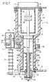
- Figure 1 there is shown in axial section, a pole of a self-disconnecting circuit breaker including improvements of the invention.
- the pole includes an insulating envelope 1 comprising a first part 1A enclosing a vacuum interrupter 2 and a second part 1B containing elements described below for the passage of the current and the operation of the bulb to empty.
- the envelope is made by molding a resin synthetic.
- the envelope comprises a metal part 4, in the form of block, one face of which is flush with the surface of the envelope for fixing the pole to the metal support rail 5.
- the block 4 has at least one threaded bore to receive one or more fixing screws.
- Block 4 is inserted into the envelope during molding thereof. This insert is advantageously placed at the junction between the parts 1A and 1B of the envelope.
- the metal insert 4 has dimensions larger than those required by the simple function of a fixing member, so that it also allow to contribute to the evacuation of calories produced by the flow of current.
- the block 4 is preferably made of aluminum or copper.
- the tube 7, intended on the one hand to conduct the current to inside the envelope by connecting the vacuum interrupter to the second contact of the pole, and on the other hand to enclose the rod 8 of the vacuum interrupter, extended by a rod 8A, is overmolded during the molding of the envelope.
- its lower part 7A is flared by 90 ° from so as to allow the joining of a plate 9 constituting the second contact of the pole.
- the solidarity of tube 7 and plate 9 is advantageously made at by means of screws 11 overmolded with the tube 7 during the molding of the casing and cooperating with nuts 12.
- the insulating envelope of the pole comprises, coming from molding, two parallel side fins framing the first contact 13 of the pole; one of these fins, referenced 14 is visible in figure 1. These fins contribute to improvement of the pole dielectric strength.
- the operating mechanism comprises, in addition to the shaft 15 movable in translation in the plane perpendicular to the plane in the figure, a bent link 16 articulated on the one hand to the shaft 15 and on the other hand to a rod 17A extending a insulating arm 17: the angled link is articulated to an axis fixed 16A secured to profile 5; the insulating arm 17 is articulated to a connecting rod 18 itself articulated to the rod 8A.
- the connecting rod 18 pivots around a fixed point A and, according to the invention, this fixed point A is located at the end of a metal element 20 inserted during molding, in the body of envelope 1. This provision ensures a precision of vacuum bulb control movements.
- the connecting rod 18 is indirectly hinged to rod 8A; the connecting rod 18 is articulated to a ring 21 surrounding the end a sheath 22 itself surrounding the end of the rod 8; a spring 23 exerts pressure between the ring 21 and the end of the sheath 22; at the end of the rod 8A, which is threaded, a shim 24 held in place by a nut 25, adjusts the distance of contacts 2A and 2B from the vacuum interrupter.
- the ring 21 and wedge 24 In the engaged position (see Fig. 3), the ring 21 and wedge 24 is no longer in contact. The distance between them decreases in the same way as the wear of the contacts of the vacuum interrupter; the measurement of this distance allows to have a visual indication of said wear accessible at the base of the pole.
- the reference 30 designates a sliding contact for electrically connecting the movable rod 8 of the vacuum interrupter and the tube 7.
- This contact is provided with channels 31 allowing ventilation between the lower part of the envelope and the space 32 between the vacuum interrupter and the envelope 1A; this ventilation, combined with the cooling produced by insert 4, provides sufficient cooling.
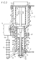
- measures are planned additional cooling, illustrated in the figure 2, which represents in partial axial section, a pole according to an alternative embodiment. These measures consist of provide a metal part 35, preferably copper, inserted during the molding of the envelope, and which has a annular volume 36 communicating through holes 37 in the tube 7 with the interior thereof. In this way, it produced by natural draft strong ventilation indicated in figure 3 by the arrows.
- the reference 40 designates a measuring torus whose role has been described in the aforementioned document.
- the pole is a simple manufacturing industrial product with a number limited parts and ease of assembly which reduce them the cost, safe operation thanks to a perfect cooling in service, adjustment possibilities as well as an indication of wear of the bulb contacts at empty.
Landscapes
- High-Tension Arc-Extinguishing Switches Without Spraying Means (AREA)
- Keying Circuit Devices (AREA)
- Oscillators With Electromechanical Resonators (AREA)
- Lock And Its Accessories (AREA)
- Percussive Tools And Related Accessories (AREA)
- Valve Device For Special Equipments (AREA)
- Control Of Vending Devices And Auxiliary Devices For Vending Devices (AREA)
Applications Claiming Priority (2)
| Application Number | Priority Date | Filing Date | Title |
|---|---|---|---|
| FR9412295A FR2725830B1 (fr) | 1994-10-14 | 1994-10-14 | Disjoncteur auto-sectionneur |
| FR9412295 | 1994-10-14 |
Publications (3)
| Publication Number | Publication Date |
|---|---|
| EP0707330A1 EP0707330A1 (fr) | 1996-04-17 |
| EP0707330B1 EP0707330B1 (fr) | 2001-08-22 |
| EP0707330B9 true EP0707330B9 (fr) | 2002-05-15 |
Family
ID=9467873
Family Applications (1)
| Application Number | Title | Priority Date | Filing Date |
|---|---|---|---|
| EP95402257A Expired - Lifetime EP0707330B9 (fr) | 1994-10-14 | 1995-10-09 | Disjoncteur auto-sectionneur |
Country Status (5)
| Country | Link |
|---|---|
| EP (1) | EP0707330B9 (es) |
| AT (1) | ATE204676T1 (es) |
| DE (1) | DE69522282T2 (es) |
| ES (1) | ES2159612T3 (es) |
| FR (1) | FR2725830B1 (es) |
Families Citing this family (5)
| Publication number | Priority date | Publication date | Assignee | Title |
|---|---|---|---|---|
| DE102004047260B4 (de) * | 2004-09-24 | 2006-08-03 | Siemens Ag | Isolierstoffgehäuse mit Belüftungsschacht |
| CN103187211A (zh) * | 2011-12-29 | 2013-07-03 | 西门子公司 | 断路器的传导装置及其断路器 |
| DE102017206754A1 (de) * | 2017-04-21 | 2018-10-25 | Siemens Aktiengesellschaft | Schaltgeräteantriebsanordnung |
| CN110911217A (zh) * | 2019-11-26 | 2020-03-24 | 深圳市安达工业设计有限公司 | 一种便于连接的新型真空开关管 |
| EP4027365A1 (en) | 2021-01-07 | 2022-07-13 | ABB Schweiz AG | A switching apparatus for electric systems |
Family Cites Families (4)
| Publication number | Priority date | Publication date | Assignee | Title |
|---|---|---|---|---|
| DE2322372C3 (de) * | 1973-04-30 | 1980-06-04 | Siemens Ag, 1000 Berlin Und 8000 Muenchen | Mehrpoliges Vakuumschaltgerät mit isolierstoffgekapselten Schaltgefäßen |
| GB1499106A (en) * | 1975-05-23 | 1978-01-25 | Ass Elect Ind | Actuating mechanism for vacuum interrupters |
| US4479042A (en) * | 1983-04-19 | 1984-10-23 | Westinghouse Electric Corp. | Contact overtravel adjustment apparatus for a vacuum contactor |
| FR2683939B1 (fr) * | 1991-11-20 | 1993-12-31 | Gec Alsthom Sa | Disjoncteur auto-sectionneur a moyenne tension et application a une cellule et a un poste a moyenne tension. |
-
1994
- 1994-10-14 FR FR9412295A patent/FR2725830B1/fr not_active Expired - Fee Related
-
1995
- 1995-10-09 EP EP95402257A patent/EP0707330B9/fr not_active Expired - Lifetime
- 1995-10-09 ES ES95402257T patent/ES2159612T3/es not_active Expired - Lifetime
- 1995-10-09 AT AT95402257T patent/ATE204676T1/de not_active IP Right Cessation
- 1995-10-09 DE DE69522282T patent/DE69522282T2/de not_active Expired - Fee Related
Also Published As
| Publication number | Publication date |
|---|---|
| ES2159612T3 (es) | 2001-10-16 |
| DE69522282D1 (de) | 2001-09-27 |
| FR2725830B1 (fr) | 1997-01-03 |
| DE69522282T2 (de) | 2002-05-16 |
| EP0707330A1 (fr) | 1996-04-17 |
| EP0707330B1 (fr) | 2001-08-22 |
| ATE204676T1 (de) | 2001-09-15 |
| FR2725830A1 (fr) | 1996-04-19 |
Similar Documents
| Publication | Publication Date | Title |
|---|---|---|
| EP0239460B1 (fr) | Disjoncteur électrique à tenue diélectrique ameliorée | |
| EP0543681B1 (fr) | Disjoncteur à moyenne tension pour l'intérieur ou l'extérieur | |
| CA1136183A (fr) | Dispositif d'insertion de resistance a la fermeture d'un appareil d'interruption | |
| EP1128509B2 (fr) | Commutateur électrique à trois positions avec un élément de commutation mobile axialement | |
| EP1571685B1 (fr) | Dispositif de fixation d'un écran dans un interrupteur électrique notamment un interrupteur à vide. | |
| FR2738389A1 (fr) | Disjoncteur hybrique a haute tension | |
| EP0540971B1 (fr) | Disjoncteur à haute ou moyenne tension à triple mouvement | |
| EP0707330B9 (fr) | Disjoncteur auto-sectionneur | |
| EP1139367B1 (fr) | Module de coupure comportant une ampoule à vide et des moyens de fixation, et appareillage electrique de coupure comportant un tel module | |
| EP0335774B1 (fr) | Déclencheur magnétique pour disjoncteur | |
| EP1003237A1 (fr) | Antenne destinée à un émetteur récepteur de radiocommunication | |
| FR2691009A1 (fr) | Sectionneur à ouverture verticale et colonne oscillante. | |
| FR2680911A1 (fr) | Sectionneur de terre a pouvoir de coupure. | |
| EP0795883A1 (fr) | Disjoncteur à autocompression réduite | |
| FR2920251A1 (fr) | Dispositif de coupure pour appareillage electrique de commutation | |
| EP0689217A1 (fr) | Ampoule sous vide, notamment pour disjoncteur ou interrupteur électrique moyenne tension et interrupteur intégrant une telle ampoule | |
| FR2581242A1 (fr) | Dispositif de commande electrique adaptable a un dispositif de commutation a deux etats | |
| FR2707429A1 (fr) | Accessoire de raccordement. | |
| FR2959592A1 (fr) | Sectionneur de terre a encombrement reduit | |
| FR2772979A1 (fr) | Dispositif de raccordement electrique d'un bloc differentiel sur un disjoncteur ou analogue et bloc differentiel equipe d'un tel dispositif | |
| FR2731553A1 (fr) | Disjoncteur auto-sectionneur a sectionnement auto-verrouille en position fermee des chambres de coupure | |
| EP1195788A1 (fr) | Pôle de disjoncteur du type à ampoule à vide | |
| FR2497397A1 (fr) | Interrupteur miniaturise a poussoir, pourvu de contacts glissants, notamment pour installations electriques de vehicules | |
| EP0749139A1 (fr) | Disjoncteur à moyenne tension et à isolement gazeux | |
| EP1512160A1 (fr) | Poste blinde a haute tension comprenant un disjoncteur avec une resistance d insertion montee dans une barre conductrice |
Legal Events
| Date | Code | Title | Description |
|---|---|---|---|
| PUAI | Public reference made under article 153(3) epc to a published international application that has entered the european phase |
Free format text: ORIGINAL CODE: 0009012 |
|
| AK | Designated contracting states |
Kind code of ref document: A1 Designated state(s): AT BE CH DE DK ES GB IT LI NL SE |
|
| 17P | Request for examination filed |
Effective date: 19960912 |
|
| GRAG | Despatch of communication of intention to grant |
Free format text: ORIGINAL CODE: EPIDOS AGRA |
|
| 17Q | First examination report despatched |
Effective date: 20001130 |
|
| GRAG | Despatch of communication of intention to grant |
Free format text: ORIGINAL CODE: EPIDOS AGRA |
|
| GRAH | Despatch of communication of intention to grant a patent |
Free format text: ORIGINAL CODE: EPIDOS IGRA |
|
| GRAH | Despatch of communication of intention to grant a patent |
Free format text: ORIGINAL CODE: EPIDOS IGRA |
|
| GRAA | (expected) grant |
Free format text: ORIGINAL CODE: 0009210 |
|
| AK | Designated contracting states |
Kind code of ref document: B1 Designated state(s): AT BE CH DE DK ES GB IT LI NL SE |
|
| PG25 | Lapsed in a contracting state [announced via postgrant information from national office to epo] |
Ref country code: NL Free format text: LAPSE BECAUSE OF FAILURE TO SUBMIT A TRANSLATION OF THE DESCRIPTION OR TO PAY THE FEE WITHIN THE PRESCRIBED TIME-LIMIT Effective date: 20010822 Ref country code: IT Free format text: LAPSE BECAUSE OF FAILURE TO SUBMIT A TRANSLATION OF THE DESCRIPTION OR TO PAY THE FEE WITHIN THE PRE;WARNING: LAPSES OF ITALIAN PATENTS WITH EFFECTIVE DATE BEFORE 2007 MAY HAVE OCCURRED AT ANY TIME BEFORE 2007. THE CORRECT EFFECTIVE DATE MAY BE DIFFERENT FROM THE ONE RECORDED.SCRIBED TIME-LIMIT Effective date: 20010822 |
|
| REF | Corresponds to: |
Ref document number: 204676 Country of ref document: AT Date of ref document: 20010915 Kind code of ref document: T |
|
| REG | Reference to a national code |
Ref country code: CH Ref legal event code: EP |
|
| GBT | Gb: translation of ep patent filed (gb section 77(6)(a)/1977) |
Effective date: 20010822 |
|
| REF | Corresponds to: |
Ref document number: 69522282 Country of ref document: DE Date of ref document: 20010927 |
|
| REG | Reference to a national code |
Ref country code: ES Ref legal event code: FG2A Ref document number: 2159612 Country of ref document: ES Kind code of ref document: T3 |
|
| PG25 | Lapsed in a contracting state [announced via postgrant information from national office to epo] |
Ref country code: LI Free format text: LAPSE BECAUSE OF NON-PAYMENT OF DUE FEES Effective date: 20011031 Ref country code: CH Free format text: LAPSE BECAUSE OF NON-PAYMENT OF DUE FEES Effective date: 20011031 Ref country code: BE Free format text: LAPSE BECAUSE OF NON-PAYMENT OF DUE FEES Effective date: 20011031 |
|
| PG25 | Lapsed in a contracting state [announced via postgrant information from national office to epo] |
Ref country code: SE Free format text: LAPSE BECAUSE OF FAILURE TO SUBMIT A TRANSLATION OF THE DESCRIPTION OR TO PAY THE FEE WITHIN THE PRESCRIBED TIME-LIMIT Effective date: 20011122 Ref country code: DK Free format text: LAPSE BECAUSE OF FAILURE TO SUBMIT A TRANSLATION OF THE DESCRIPTION OR TO PAY THE FEE WITHIN THE PRESCRIBED TIME-LIMIT Effective date: 20011122 |
|
| REG | Reference to a national code |
Ref country code: GB Ref legal event code: IF02 |
|
| NLV1 | Nl: lapsed or annulled due to failure to fulfill the requirements of art. 29p and 29m of the patents act | ||
| BERE | Be: lapsed |
Owner name: S.A. GEC ALSTHOM T ET D Effective date: 20011031 |
|
| REG | Reference to a national code |
Ref country code: CH Ref legal event code: PL |
|
| PLBE | No opposition filed within time limit |
Free format text: ORIGINAL CODE: 0009261 |
|
| STAA | Information on the status of an ep patent application or granted ep patent |
Free format text: STATUS: NO OPPOSITION FILED WITHIN TIME LIMIT |
|
| 26N | No opposition filed | ||
| PGFP | Annual fee paid to national office [announced via postgrant information from national office to epo] |
Ref country code: GB Payment date: 20041006 Year of fee payment: 10 |
|
| PGFP | Annual fee paid to national office [announced via postgrant information from national office to epo] |
Ref country code: AT Payment date: 20041013 Year of fee payment: 10 |
|
| PGFP | Annual fee paid to national office [announced via postgrant information from national office to epo] |
Ref country code: ES Payment date: 20041021 Year of fee payment: 10 |
|
| PGFP | Annual fee paid to national office [announced via postgrant information from national office to epo] |
Ref country code: DE Payment date: 20041023 Year of fee payment: 10 |
|
| PG25 | Lapsed in a contracting state [announced via postgrant information from national office to epo] |
Ref country code: GB Free format text: LAPSE BECAUSE OF NON-PAYMENT OF DUE FEES Effective date: 20051009 Ref country code: AT Free format text: LAPSE BECAUSE OF NON-PAYMENT OF DUE FEES Effective date: 20051009 |
|
| PG25 | Lapsed in a contracting state [announced via postgrant information from national office to epo] |
Ref country code: ES Free format text: LAPSE BECAUSE OF NON-PAYMENT OF DUE FEES Effective date: 20051010 |
|
| PG25 | Lapsed in a contracting state [announced via postgrant information from national office to epo] |
Ref country code: DE Free format text: LAPSE BECAUSE OF NON-PAYMENT OF DUE FEES Effective date: 20060503 |
|
| GBPC | Gb: european patent ceased through non-payment of renewal fee |
Effective date: 20051009 |
|
| REG | Reference to a national code |
Ref country code: ES Ref legal event code: FD2A Effective date: 20051010 |