EP0707196B1 - System and method for detecting the relative position and motions between a rail vehicle and track - Google Patents
System and method for detecting the relative position and motions between a rail vehicle and track Download PDFInfo
- Publication number
- EP0707196B1 EP0707196B1 EP95830075A EP95830075A EP0707196B1 EP 0707196 B1 EP0707196 B1 EP 0707196B1 EP 95830075 A EP95830075 A EP 95830075A EP 95830075 A EP95830075 A EP 95830075A EP 0707196 B1 EP0707196 B1 EP 0707196B1
- Authority
- EP
- European Patent Office
- Prior art keywords
- track
- axles
- detecting
- displacement
- relative
- Prior art date
- Legal status (The legal status is an assumption and is not a legal conclusion. Google has not performed a legal analysis and makes no representation as to the accuracy of the status listed.)
- Expired - Lifetime
Links
- 238000000034 method Methods 0.000 title claims description 9
- 230000033001 locomotion Effects 0.000 title description 5
- 238000006073 displacement reaction Methods 0.000 claims abstract description 56
- 238000012545 processing Methods 0.000 claims abstract description 14
- 238000012544 monitoring process Methods 0.000 claims abstract description 8
- 238000005096 rolling process Methods 0.000 claims description 5
- 238000005259 measurement Methods 0.000 description 3
- 230000003287 optical effect Effects 0.000 description 3
- 238000004364 calculation method Methods 0.000 description 2
- 238000011156 evaluation Methods 0.000 description 2
- 238000012360 testing method Methods 0.000 description 2
- 230000005540 biological transmission Effects 0.000 description 1
- 230000001143 conditioned effect Effects 0.000 description 1
- 238000013016 damping Methods 0.000 description 1
- 230000008846 dynamic interplay Effects 0.000 description 1
- 230000002093 peripheral effect Effects 0.000 description 1
- 239000000725 suspension Substances 0.000 description 1
Images

Classifications
-
- G—PHYSICS
- G01—MEASURING; TESTING
- G01D—MEASURING NOT SPECIALLY ADAPTED FOR A SPECIFIC VARIABLE; ARRANGEMENTS FOR MEASURING TWO OR MORE VARIABLES NOT COVERED IN A SINGLE OTHER SUBCLASS; TARIFF METERING APPARATUS; MEASURING OR TESTING NOT OTHERWISE PROVIDED FOR
- G01D5/00—Mechanical means for transferring the output of a sensing member; Means for converting the output of a sensing member to another variable where the form or nature of the sensing member does not constrain the means for converting; Transducers not specially adapted for a specific variable
- G01D5/26—Mechanical means for transferring the output of a sensing member; Means for converting the output of a sensing member to another variable where the form or nature of the sensing member does not constrain the means for converting; Transducers not specially adapted for a specific variable characterised by optical transfer means, i.e. using infrared, visible, or ultraviolet light
-
- B—PERFORMING OPERATIONS; TRANSPORTING
- B61—RAILWAYS
- B61F—RAIL VEHICLE SUSPENSIONS, e.g. UNDERFRAMES, BOGIES OR ARRANGEMENTS OF WHEEL AXLES; RAIL VEHICLES FOR USE ON TRACKS OF DIFFERENT WIDTH; PREVENTING DERAILING OF RAIL VEHICLES; WHEEL GUARDS, OBSTRUCTION REMOVERS OR THE LIKE FOR RAIL VEHICLES
- B61F5/00—Constructional details of bogies; Connections between bogies and vehicle underframes; Arrangements or devices for adjusting or allowing self-adjustment of wheel axles or bogies when rounding curves
- B61F5/50—Other details
-
- B—PERFORMING OPERATIONS; TRANSPORTING
- B61—RAILWAYS
- B61K—AUXILIARY EQUIPMENT SPECIALLY ADAPTED FOR RAILWAYS, NOT OTHERWISE PROVIDED FOR
- B61K9/00—Railway vehicle profile gauges; Detecting or indicating overheating of components; Apparatus on locomotives or cars to indicate bad track sections; General design of track recording vehicles
- B61K9/08—Measuring installations for surveying permanent way
Definitions
- the present invention is related in general to rail vehicles having axles and masses which are sprung and movable relative to these axles. More particularly, the invention is directed to a system for detecting the relative position of said sprung masses relative to the track and relative to the single axles in view of obtaining, through processing of the detected data, information about the relative motions of each of these bodies (sprung mass/axles) both mutually and with respect to the track, on the basis of the dynamic interactions which are exchanged between these bodies.
- optical detecting equipments on railway vehicles contemplate monitoring the contour profile of the wheels by means of optical laser transducers, such as in the case of British Patent Application GB-A-2.178.169.
- the object of the present invention is to provide a detecting system and method for railway vehicles by means of which data can be obtained for the evaluation of the friction work between the wheels and rails for wear forecasting, as well as for checking the running attitude of the axles and of the mass sprung thereover, and locating relative amplitude and phases of the dynamic phenomena of these members, so as to allow corrective means to be introduced.
- the system and method according to the invention are particularly directed to the achievement, in extremely short times, of testing and setup evaluations of railway bogies by the manufacturers, to the aim of ascertaining the consequences of any constructive irregularities and determining the locations at which it may be possibly necessary to introduce damping devices or different corrective means so as to improve the dynamic behaviour of the railway vehicle, and in particular to prevent any dynamic instability thereof.
- a detecting system on a railway vehicle having at least two axles and a mass (hereinafter designated as "structure") which is sprung over and movable relative to said axles, comprising:
- said position detecting means comprise two pairs of laser transducers applied on the opposite sides of respective transverse sections of the structure and oriented towards the inner flanks of the track rails, and a further laser transducer applied on one side of an intermediate transverse section of the structure and oriented towards the inner flank of the corresponding rail adjacent thereto of the track.
- the displacement detecting means which characterize the relative position between each axle subjected to measurement and the sprung mass or structure, conveniently comprise two pairs of vertical displacement transducers, two pairs of longitudinal displacement transducers, and two lateral displacement transducers, operatively associated to supports fixedly connected to non-rotating parts of the two axles.
- the vertical, longitudinal and lateral displacement transducers may preferably, but not necessarily, be of a mechanical-linear type, for instance of the differential transformer type.
- the processing means are to advantage adapted to provide the following data:
- reference C generally designates in its entirety a two-axle bogie intended to be employed in a railway vehicle (not shown), comprising traditionally a body and a second bogie quite identical to the bogie C.
- this bogie C comprises a frame structure F and a pair of axles A1, A2 having respective wheels W11, W12 and W21, W22 arranged in proximity of the ends (front end and rear end, respectively) of the frame F.
- the opposite ends of each axle A1, A2 are connected to the opposite sides of the frame F, also in a conventional way, by means of respective journal boxes B11, B12 and B21, B22.
- a primary spring suspension system diagrammatically depicted in figure 1, is conventionally interposed between the axles A1, A2 and the frame F.
- the bogie C is equipped with a detecting system employing a series of transducers, the location of which is diagrammatically depicted in figures 1 and 2, connected through conventional acquisition systems of the respective output signals, normally of the digitizing board type, to a programmable micro-processor electronic unit (not shown in the drawings).
- transducers by means of which as it will be apparent in the following the dynamic phenomena of the bogie when running along the rails T1, T2 are monitorized, comprise two groups: a first group including position transducers, adapted to detect typical geometrical characteristics of the track and the relative position between the axles A1, A2 and the respective rails T1, T2 in the running condition of the vehicle and to provide corresponding electrical signals indicative of the detected entities, and a second group including displacement transducers, adapted to detect the relative displacements between the frame F of the bogie C and the axles A1, A2, and to provide electrical signals indicative of the detected entities.
- position transducers adapted to detect typical geometrical characteristics of the track and the relative position between the axles A1, A2 and the respective rails T1, T2 in the running condition of the vehicle and to provide corresponding electrical signals indicative of the detected entities
- displacement transducers adapted to detect the relative displacements between the frame F of the bogie C and the axles A1, A2, and to provide electrical signals indicative of the detected entities.
- the position transducer group comprises:
- the photosensors L11, L12, L21, L22, LM are conveniently (but not necessarily) of the laser emitter type, for instance having a detecting range of 325 ⁇ 40 mm, a 12 bit resolution, a detecting frequency of 16 kHz and a passband selectable between 10 Hz and 2 kHz.
- This type of photosensor is operating, in a way known per se, according to the generation of two electronic currents which are proportional to the position of an infrared spot focused onto the surface thereof.
- the object to be detected (in the instant case the inner flank of the rail) reflects in all directions the light energy projected onto its surface by the emitter: a portion of this reflected energy is focused on the receiver, through which electrical signals indicative of the position of the rail inner flank relative to the emitter are generated.
- These electrical signals supplied by the receiver are treated via a signal conditioner, normally including in a way known per se a linearization circuit with low-pass analogical filter.
- the conditioned signals are then fed to an acquisition board for digitizing and transmission thereof to the electronic processing unit.
- the group of displacement sensors comprises a series of mechanical transducers, for instance of the differential transformer linear type LVDT, the function of which is to detect the relative displacements between the frame F of the bogie C and the axles A1, A2, and to supply electrical signals indicative of these displacements. More particularly, the group of the displacement sensors comprises:
- displacement transducers X11, X12, X21, X22; V11, V12, V21, V22; R1, R2 are connected to the electronic processing unit via digitizing boards.
- the electronic processing unit may consists for instance of a 386 and/or 486 personal computer with associated peripheral units.
- the detecting system is further operatively connected to an odometer device of a conventional type (indicated as ODO in the flow chart of figure 3) for the measurement of distance and speed during running of the vehicle, to the aim of obtaining spatial references for the measurements performed and processed by the system.
- ODO odometer device of a conventional type
- Figure 3 diagrammatically shows the processing flow chart of the signals generated by the two groups of position and displacement transducers, respectively, previously disclosed.
- a series of data is calculated, indicative both of typical geometrical characteristics of the track, and of the relative position between the axles and the track in the running condition of the bogie C.
- the data related to the track characteristics are the following: average curvature (1), rail gauge in two sections corresponding to the front side and to the rear side of the bogie (2, 3), track skew on the basis of the bogie wheel base (4).
- the most relevant intermediate magnitude is the relative displacement in the horizontal transverse direction of the rails with respect to the structure in correspondence of each laser transducer: this magnitude shall be indicated hereinafter as "corrected laser”.
- the calculation of the corrected laser values is carried out by means of a trigonometric relationship which takes into account the angles of inclination of the laser transducers, which result from the sum of the fixed mounting angles of the transducers and the angles generated by the movements of the structure. These angles can be deduced as a function of the signals of the mechanical transducers and the mounting positions thereof.
- the curvature of the rail towards which the laser transducers L11, LM and L21 are oriented is calculated through a linear combination relationship among the signals of these three corrected laser transducers so as to determine the longitudinal misalignment between the detecting points of the laser transducers themselves. From the value of this misalignment and the mutual distances between the laser transducers, the curvature and thus the curve radius can be obtained.
- the rail gauge detected in the two transverse sections corresponding to the laser transducers L11-L21, and L21-L22 corresponds to the difference between the corrected laser signals, and represents the variation of the rail gauge with respect to the nominal value.
- the relative axle-track displacement is calculated by means of the difference between the lateral displacement of the center of the axle and the displacement of the center of the rail.
- the former is calculated through a linear combination of the movements of the structure and of the relative displacement between axle and structure.
- the latter is calculated as the arithmetical mean between the corrected laser L11-L12, L21-L22 signals of the first and second axle, respectively.
- the angle of attack is evaluated as algebrical sum of the relative angle between each axle and the structure, calculated through a linear combination of the signals supplied by the longitudinal transducers, of the angle between the structure and track, calculated as a linear combination of the corrected laser signals supplied by the four end laser transducers, and of the geometrical angle due to the track curvature in correspondence of the first and second axle.
- the data thus obtained enable globally evaluating and monitoring the dynamic behaviour of the bogie in terms of attitude, centering, relative amplitudes and phases of the motions of the various components, as well as to determine consequently the friction work between the wheels and rails for wear forecasting.
- the system of the invention allows testing and setup of the bogie, i.e. of the vehicle equipped with the bogie itself, to be carried out quickly and with reliable and accurate results.
Landscapes
- Mechanical Engineering (AREA)
- Engineering & Computer Science (AREA)
- Physics & Mathematics (AREA)
- General Physics & Mathematics (AREA)
- Length Measuring Devices With Unspecified Measuring Means (AREA)
- Length Measuring Devices By Optical Means (AREA)
- Train Traffic Observation, Control, And Security (AREA)
- Electric Propulsion And Braking For Vehicles (AREA)
- Automobile Manufacture Line, Endless Track Vehicle, Trailer (AREA)
- Radar Systems Or Details Thereof (AREA)
- Platform Screen Doors And Railroad Systems (AREA)
- Vehicle Cleaning, Maintenance, Repair, Refitting, And Outriggers (AREA)
- Casting Support Devices, Ladles, And Melt Control Thereby (AREA)
Abstract
Description
- The present invention is related in general to rail vehicles having axles and masses which are sprung and movable relative to these axles. More particularly, the invention is directed to a system for detecting the relative position of said sprung masses relative to the track and relative to the single axles in view of obtaining, through processing of the detected data, information about the relative motions of each of these bodies (sprung mass/axles) both mutually and with respect to the track, on the basis of the dynamic interactions which are exchanged between these bodies.
- In the field of railway vehicles it is known to provide the bogies thereof with optical detecting equipments, also with the aid of laser transducers, to the aim of inspecting and monitoring the railway line, for instance in terms of geometry, alignment and spacing of the rails. Examples representing these applications are disclosed and illustrated in French Patent Application FR-A-2.674.809 and in European Patent Application EP-A-0293015.
- Other applications of optical detecting equipments on railway vehicles contemplate monitoring the contour profile of the wheels by means of optical laser transducers, such as in the case of British Patent Application GB-A-2.178.169.
- The object of the present invention is to provide a detecting system and method for railway vehicles by means of which data can be obtained for the evaluation of the friction work between the wheels and rails for wear forecasting, as well as for checking the running attitude of the axles and of the mass sprung thereover, and locating relative amplitude and phases of the dynamic phenomena of these members, so as to allow corrective means to be introduced.
- The system and method according to the invention are particularly directed to the achievement, in extremely short times, of testing and setup evaluations of railway bogies by the manufacturers, to the aim of ascertaining the consequences of any constructive irregularities and determining the locations at which it may be possibly necessary to introduce damping devices or different corrective means so as to improve the dynamic behaviour of the railway vehicle, and in particular to prevent any dynamic instability thereof.
- According to the invention, the above object is achieved by virtue of a detecting system on a railway vehicle having at least two axles and a mass (hereinafter designated as "structure") which is sprung over and movable relative to said axles, comprising:
- photosensor position-detecting means applied to the structure and adapted to detect typical geometrical characteristics of the track and the relative position between said structure and the rails in the running condition of the vehicle along the track, and to provide electrical signals indicative of said geometrical characteristics and said relative position,
- displacement detecting means also applied to said structure and adapted to detect the relative displacements between said structure and each of said axles, and to provide electrical signals indicative of said displacements,
- electronic acquisition and processing means of said electrical signals, adapted to provide a monitoring related to the track configuration and to the dynamic attitude of said structure.
- According to a preferred embodiment of the invention, said position detecting means comprise two pairs of laser transducers applied on the opposite sides of respective transverse sections of the structure and oriented towards the inner flanks of the track rails, and a further laser transducer applied on one side of an intermediate transverse section of the structure and oriented towards the inner flank of the corresponding rail adjacent thereto of the track.
- The displacement detecting means, which characterize the relative position between each axle subjected to measurement and the sprung mass or structure, conveniently comprise two pairs of vertical displacement transducers, two pairs of longitudinal displacement transducers, and two lateral displacement transducers, operatively associated to supports fixedly connected to non-rotating parts of the two axles.
- The vertical, longitudinal and lateral displacement transducers may preferably, but not necessarily, be of a mechanical-linear type, for instance of the differential transformer type.
- The processing means are to advantage adapted to provide the following data:
- in connection with the track configuration: rail gauge in correspondence of each transverse section, average curvature (conveniently detected by three laser transducers oriented towards the same rail) and track skew on the basis of the wheel base between the axles;
- in connection with the dynamic attitude of the structure and of the single axles: lateral displacements between the structure and the track, hunting, rolling, pitching, shaking, relative displacement between each axle and track, angle of attack between each axle and track.
- The method according to the invention, which employs the system such as set forth in the above, consists of the following steps:
- detecting typical geometrical characteristics of the track and the relative position between the axles and rails in the running condition of the vehicle along the track, by means of photosensor position-detecting means applied to the structure and oriented towards the inner flanks of the track rails,
- obtaining from said detecting step electrical signals indicative of said geometrical characteristics and said relative position,
- detecting the relative displacements between the structure and the axles in the running condition of the vehicle along the track, by means of displacement detecting means operatively associated to supports fixedly connected to the non rotating parts of each of said two axles,
- obtaining from said detecting step electrical signals indicative of such displacements,
- processing said electrical signals so as to provide a monitoring in connection with the configuration of the track and the dynamic attitude of the structure and of the two axles.
- The invention will now be disclosed in detail with reference to the accompanying drawings, purely provided by way of non-limiting example, in which:
- figure 1 is a diagrammatic side elevational and partially sectioned view of a two-axle bogie for railway vehicle equipped with a detecting system according to the invention,
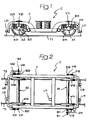
- figure 2 is a top plan view of figure 1, and
- figure 3 is a flow chart showing the processing logic of the signals generated in the detecting system according to the invention.
- Referring initially to figures 1 and 2, reference C generally designates in its entirety a two-axle bogie intended to be employed in a railway vehicle (not shown), comprising traditionally a body and a second bogie quite identical to the bogie C.
- Briefly, this bogie C comprises a frame structure F and a pair of axles A1, A2 having respective wheels W11, W12 and W21, W22 arranged in proximity of the ends (front end and rear end, respectively) of the frame F. The opposite ends of each axle A1, A2 are connected to the opposite sides of the frame F, also in a conventional way, by means of respective journal boxes B11, B12 and B21, B22.
- A primary spring suspension system, diagrammatically depicted in figure 1, is conventionally interposed between the axles A1, A2 and the frame F.
- According to the invention, the bogie C is equipped with a detecting system employing a series of transducers, the location of which is diagrammatically depicted in figures 1 and 2, connected through conventional acquisition systems of the respective output signals, normally of the digitizing board type, to a programmable micro-processor electronic unit (not shown in the drawings).
- These transducers, by means of which as it will be apparent in the following the dynamic phenomena of the bogie when running along the rails T1, T2 are monitorized, comprise two groups: a first group including position transducers, adapted to detect typical geometrical characteristics of the track and the relative position between the axles A1, A2 and the respective rails T1, T2 in the running condition of the vehicle and to provide corresponding electrical signals indicative of the detected entities, and a second group including displacement transducers, adapted to detect the relative displacements between the frame F of the bogie C and the axles A1, A2, and to provide electrical signals indicative of the detected entities.
- In better detail, the position transducer group comprises:
- a first pair of photosensors, preferably of the laser type, indicated as L11 and L12, applied on opposite sides in correspondence of the front end of the frame F, in front of the axles A1, and oriented towards the inner flanks of the rails T1 and T2, respectively;
- a second pair of photosensors, also preferably of the laser type, designated as L21 and L22 and applied on opposite sides in correspondence of the rear end of the frame F, behind the axle A2, and also oriented towards the inner flanks of the rails T1, T2 respectively;
- a further photosensor, also normally of the laser type, indicated as LM and applied on one side of an intermediate area of the frame F and oriented towards the inner flank of the corresponding rail T1. As it can be clearly seen in figure 2, the position of the photosensor LM may conveniently be offset with respect to the transverse center line of the bogie C, whereby its distance from the front axle A1 is different, and in the case of the shown example less, than its distance with respect to the rear axle A2.
- As explained in the above, the photosensors L11, L12, L21, L22, LM are conveniently (but not necessarily) of the laser emitter type, for instance having a detecting range of 325 ± 40 mm, a 12 bit resolution, a detecting frequency of 16 kHz and a passband selectable between 10 Hz and 2 kHz. This type of photosensor is operating, in a way known per se, according to the generation of two electronic currents which are proportional to the position of an infrared spot focused onto the surface thereof. The object to be detected (in the instant case the inner flank of the rail) reflects in all directions the light energy projected onto its surface by the emitter: a portion of this reflected energy is focused on the receiver, through which electrical signals indicative of the position of the rail inner flank relative to the emitter are generated. These electrical signals supplied by the receiver are treated via a signal conditioner, normally including in a way known per se a linearization circuit with low-pass analogical filter. The conditioned signals are then fed to an acquisition board for digitizing and transmission thereof to the electronic processing unit.
- The group of displacement sensors comprises a series of mechanical transducers, for instance of the differential transformer linear type LVDT, the function of which is to detect the relative displacements between the frame F of the bogie C and the axles A1, A2, and to supply electrical signals indicative of these displacements. More particularly, the group of the displacement sensors comprises:
- two pairs of longitudinal displacement transducers X11, X12 and X21, X22 for detecting displacements in the longitudinal direction of the journal boxes B11, B12 of the axle A1, and of the journal boxes B21, B22 of the axle A2, respectively, relative to the frame F of the bogie C;
- two pairs of vertical displacement transducers V11, V12 and V21, V22 for detecting the vertical displacements of the journal boxes B11 and B12 of the axle A1 and of the journal boxes B21 and B22 of the axle A2, respectively, relative to the frame F of the bogie C,
- two lateral displacement transducers R1, R2 frontally facing the journal box B11 and the journal box B22, respectively, for detecting displacement in the transverse direction of the axles A1 and A2, respectively, relative to the frame F of the bogie C.
- Also the displacement transducers X11, X12, X21, X22; V11, V12, V21, V22; R1, R2 are connected to the electronic processing unit via digitizing boards.
- The electronic processing unit may consists for instance of a 386 and/or 486 personal computer with associated peripheral units.
- The detecting system is further operatively connected to an odometer device of a conventional type (indicated as ODO in the flow chart of figure 3) for the measurement of distance and speed during running of the vehicle, to the aim of obtaining spatial references for the measurements performed and processed by the system.
- Figure 3 diagrammatically shows the processing flow chart of the signals generated by the two groups of position and displacement transducers, respectively, previously disclosed. Through suitable mathematical algorithms which shall be briefly disclosed herebelow, and in an approximation hypothesis according to which the rails T1 and T2 are considered as "ideal" (i.e. having a vertical or constantly slanting inner flank), a series of data is calculated, indicative both of typical geometrical characteristics of the track, and of the relative position between the axles and the track in the running condition of the bogie C.
- More in detail, according to the chart of figure 3 and with reference to the blocks indicated therein by respective numerals, the data related to the track characteristics are the following: average curvature (1), rail gauge in two sections corresponding to the front side and to the rear side of the bogie (2, 3), track skew on the basis of the bogie wheel base (4).
- The data obtained in connection with the dynamic behaviour of the bogie are as follows: relative bogietrack lateral displacement (5), relative hunting between the bogie and each axle (6, 7), bogie hunting (8), bogie rolling in correspondence of each axle (9, 10), average bogie rolling (11), bogie pitching (12), bogie shaking (13), relative displacement between each axle and track (14, 15), angle of attack between each axle and track (16, 17).
- For the calculation of the final magnitudes defining the position of the bogie relative to the track, it is necessary to process the signals supplied by the transducers, to obtain therefrom certain intermediate values, and to perform a few suitable combinations between the signals themselves. The most relevant intermediate magnitude is the relative displacement in the horizontal transverse direction of the rails with respect to the structure in correspondence of each laser transducer: this magnitude shall be indicated hereinafter as "corrected laser".
- The calculation of the corrected laser values is carried out by means of a trigonometric relationship which takes into account the angles of inclination of the laser transducers, which result from the sum of the fixed mounting angles of the transducers and the angles generated by the movements of the structure. These angles can be deduced as a function of the signals of the mechanical transducers and the mounting positions thereof.
- The curvature of the rail towards which the laser transducers L11, LM and L21 are oriented is calculated through a linear combination relationship among the signals of these three corrected laser transducers so as to determine the longitudinal misalignment between the detecting points of the laser transducers themselves. From the value of this misalignment and the mutual distances between the laser transducers, the curvature and thus the curve radius can be obtained.
- The rail gauge detected in the two transverse sections corresponding to the laser transducers L11-L21, and L21-L22, corresponds to the difference between the corrected laser signals, and represents the variation of the rail gauge with respect to the nominal value.
- The relative axle-track displacement is calculated by means of the difference between the lateral displacement of the center of the axle and the displacement of the center of the rail. The former is calculated through a linear combination of the movements of the structure and of the relative displacement between axle and structure. The latter is calculated as the arithmetical mean between the corrected laser L11-L12, L21-L22 signals of the first and second axle, respectively.
- The angle of attack is evaluated as algebrical sum of the relative angle between each axle and the structure, calculated through a linear combination of the signals supplied by the longitudinal transducers, of the angle between the structure and track, calculated as a linear combination of the corrected laser signals supplied by the four end laser transducers, and of the geometrical angle due to the track curvature in correspondence of the first and second axle.
- In practice, the data thus obtained enable globally evaluating and monitoring the dynamic behaviour of the bogie in terms of attitude, centering, relative amplitudes and phases of the motions of the various components, as well as to determine consequently the friction work between the wheels and rails for wear forecasting. In summary, the system of the invention allows testing and setup of the bogie, i.e. of the vehicle equipped with the bogie itself, to be carried out quickly and with reliable and accurate results.
Claims (10)
- A detecting system on a railway vehicle having at least two axles (A1, A2) and a mass or structure (F) which is sprung over and movable relative to said axles (A1, A2), comprising:photosensor position-detecting means (L11, L12, L21, L22, LM) applied to the structure (F) and adapted to detect typical geometrical characteristics of the track (T1, T2) and the relative position between said structure (F) and the rails in the running condition of the vehicle along the track, and to provide electrical signals indicative of said geometrical characteristics and said relative position,displacement detecting means also applied to said structure (F) and adapted to detect the relative displacements between said structure (F) and each of said axles (A1, A2), and to provide electrical signals indicative of said displacements,electronic acquisition and processing means of said electrical signals, adapted to provide a monitoring related to the track (T1, T2) configuration and to the dynamic attitude of said structure (F).
- Detecting system according to claim 1, characterized in that said position detecting means comprise two pairs of laser transducers (L11, L12; L21, L22) applied on opposite sides of respective transverse sections of the structure (F) and oriented towards the inner flanks of the track rails (T1, T2), and a further laser transducer (LM) applied on one side of an intermediate transverse section of the structure and oriented towards the inner flank of the corresponding rail (T1) adjacent thereto of the track.
- Detecting system according to claim 1 or 2, characterized in that said displacement detecting means comprise for each axle (A1, A2) a pair of vertical displacement transducers (V11, V12; V21, V22), a pair of longitudinal displacement transducers (X11, X12; X21, X22) and a lateral displacement transducer (R1, R2), operatively associated to supports fixedly connected to non rotating parts (B11, B12; B21, B22) of the respective axle (A1, A2).
- Detecting system according to claim 3, characterized in that said vertical, longitudinal and lateral displacement transducers (V, X, R) are of mechanical type, preferably comprising linear differential transformers.
- Detecting system according to claim 3, characterized in that said processing means are adapted to provide the following data:in connection with the track (T1, T2) configuration: rail gauge in correspondence of each transverse section, average curvature and track skew on the basis of the wheel base between the axles (A1, A2);in connection with the dynamic attitude of the structure (F) and of the single axles (A1, A2): structure-track lateral displacements, hunting, rolling, pitching, shaking, relative displacement between each axle and track, angle of attack between each axle and track.
- Detecting system according to any of the preceding claims, characterized in that said structure is a railway bogie (C) frame (F).
- A detecting method for railway vehicles having at least two axles (A1, A2) and a sprung mass or structure (F) movable relative to said axles, consisting of the following steps:detecting typical geometrical characteristics of the track (T1, T2) and the relative position between the axles (A1, A2) and rails (T1, T2) in the running condition of the vehicle along the track, by means of photosensor position-detecting means (L) applied to the structure (F) and oriented towards the inner flanks of the track rails,obtaining from said detecting step electrical signals indicative of said geometrical characteristics and said relative position,detecting the relative displacements between the structure (F) and the axles (A1, A2) in the running condition of the vehicle along the track by means of displacement detecting means (V, X, R) operatively associated to supports fixedly connected to the non rotating parts (B) of each of said two axles (A1, A2),obtaining from said detecting step electrical signals indicative of such displacements,processing said electrical signals so as to provide a monitoring in connection with the track (T1, T2) configuration and the dynamic attitude of the structure (F) and of the two axles (A1, A2).
- Method according to claim 7, characterized in that two pairs of laser transducers (L11, L12; L21, L22) are employed as said position detecting means, which are applied on opposite sides of respective transverse sections of the structure (F) and oriented towards the inner flanks of the track rails (T1, T2), and a further laser transducer (LM) is applied on one side of an intermediate transverse section of the structure (F) and is oriented towards the inner flank of the corresponding rail (T1).
- Method according to claim 8, characterized in that two pairs of vertical displacement transducers (V11, V12; V21, V22), two pairs of longitudinal displacement transducers (X11, X12; X21, X22) and two lateral displacement transducers (R1, R2) are employed as said displacement detecting means and are operatively associated to the journal boxes (B11, B12; B21, B22) of the two axles (A1, A2).
- Method according to claim 7, characterized in that said processing means provide the following data:in connection with the configuration of the track (T1, T2): rail gauge in correspondence of each transverse section, average curvature and track skew on the basis of the wheel base between the axles (A1, A2);in connection with the dynamic attitude of the structure (F) and of the single axles (A1, A2): structure-track lateral displacements, hunting, rolling, pitching, shaking, relative displacement between each axle and track, angle of attack between each axle and track.
Applications Claiming Priority (2)
| Application Number | Priority Date | Filing Date | Title |
|---|---|---|---|
| IT94TO000817A IT1268122B1 (en) | 1994-10-13 | 1994-10-13 | SYSTEM AND PROCEDURE FOR DETECTION OF THE POSITION AND OF THE RELATIVE MOTIONS OF VEHICLES ON RAIL WITH RESPECT TO THE TRACK |
| ITTO940817 | 1994-10-13 |
Publications (3)
| Publication Number | Publication Date |
|---|---|
| EP0707196A2 EP0707196A2 (en) | 1996-04-17 |
| EP0707196A3 EP0707196A3 (en) | 1997-06-11 |
| EP0707196B1 true EP0707196B1 (en) | 1999-08-04 |
Family
ID=11412832
Family Applications (1)
| Application Number | Title | Priority Date | Filing Date |
|---|---|---|---|
| EP95830075A Expired - Lifetime EP0707196B1 (en) | 1994-10-13 | 1995-03-06 | System and method for detecting the relative position and motions between a rail vehicle and track |
Country Status (8)
| Country | Link |
|---|---|
| US (1) | US5596203A (en) |
| EP (1) | EP0707196B1 (en) |
| JP (1) | JPH08122042A (en) |
| AT (1) | ATE182984T1 (en) |
| DE (1) | DE69511203D1 (en) |
| FI (1) | FI952231A (en) |
| IT (1) | IT1268122B1 (en) |
| NO (1) | NO952006L (en) |
Cited By (1)
| Publication number | Priority date | Publication date | Assignee | Title |
|---|---|---|---|---|
| WO2013056289A1 (en) | 2011-10-20 | 2013-04-25 | Isiqiri Interface Technolgies Gmbh | Real-time measurement of relative position data and/or of geometrical dimensions of a moving body using optical measuring means |
Families Citing this family (26)
| Publication number | Priority date | Publication date | Assignee | Title |
|---|---|---|---|---|
| US5850197A (en) * | 1997-08-25 | 1998-12-15 | Trimble Navigation | Attitude determination using fewer than three antennas |
| GB9911170D0 (en) * | 1999-05-14 | 1999-07-14 | Aea Technology Plc | Track monitoring equipment |
| FR2798347B1 (en) * | 1999-09-09 | 2001-11-30 | Matisa Materiel Ind Sa | VEHICLE FOR MEASURING THE GEOMETRIC STATE OF A RAILWAY |
| SE517080C2 (en) * | 2000-08-18 | 2002-04-09 | Volvo Articulated Haulers Ab | Device for wheel suspension and vehicles with such suspension |
| KR100418774B1 (en) * | 2000-12-26 | 2004-02-18 | 현대자동차주식회사 | Between frame and axle relativity displacement determination controlled device of vehicle and method thereof |
| US6637703B2 (en) | 2000-12-28 | 2003-10-28 | Ge Harris Railway Electronics Llc | Yard tracking system |
| GB0116651D0 (en) * | 2001-07-07 | 2001-08-29 | Aea Technology Plc | Track monitoring equipment |
| EP1747135A4 (en) * | 2004-05-03 | 2008-11-12 | Sti Global Ltd | Train integrity network system |
| JP2006142987A (en) * | 2004-11-19 | 2006-06-08 | Kinki Sharyo Co Ltd | Railway vehicle |
| US20070108713A1 (en) * | 2005-11-15 | 2007-05-17 | Javid Ali | Rolling utility knife |
| US7714886B2 (en) * | 2006-03-07 | 2010-05-11 | Lynxrail Corporation | Systems and methods for obtaining improved accuracy measurements of moving rolling stock components |
| DE102007016395B3 (en) * | 2007-04-03 | 2008-07-03 | Db Netz Ag | Vehicle-specific quantification function determining method for track, involves determining regression coefficients for vehicle reaction by satisfying preset vehicle-specific quantification equation |
| WO2008122319A1 (en) * | 2007-04-05 | 2008-10-16 | Siemens Transportation Systems Gmbh & Co. Kg | Measuring arrangement for the contactless and continuous determination of routing and track layout of railroad tracks |
| EP2171158B1 (en) * | 2007-07-17 | 2021-02-17 | Wabtec Control Systems Pty Ltd | System and method for analyzing rolling stock wheels |
| DE102007051126A1 (en) | 2007-10-24 | 2009-04-30 | Bombardier Transportation Gmbh | Determination of the remaining service life of a vehicle component |
| JP5959378B2 (en) * | 2012-09-11 | 2016-08-02 | 川崎重工業株式会社 | Load measuring method and apparatus, railway vehicle equipped with load measuring apparatus, and load management system |
| US9536311B2 (en) * | 2014-09-29 | 2017-01-03 | General Electric Company | System and method for component detection |
| CN106289059B (en) * | 2016-08-31 | 2019-05-21 | 中车青岛四方机车车辆股份有限公司 | Bogie detection device |
| AT519263B1 (en) * | 2016-12-19 | 2018-05-15 | Plasser & Theurer Export Von Bahnbaumaschinen Gmbh | Track measuring vehicle and method for detecting a track geometry of a track |
| AT519003B1 (en) * | 2016-12-19 | 2018-03-15 | Plasser & Theurer Export Von Bahnbaumaschinen Gmbh | Measuring device and method for detecting a track geometry |
| CN109017872B (en) * | 2018-07-23 | 2020-02-18 | 清华大学天津高端装备研究院 | Preventative maintenance method and device for train wheels and storage medium |
| CN108944998B (en) * | 2018-07-23 | 2020-10-30 | 清华大学天津高端装备研究院 | Train wheel detection and maintenance system |
| CN113239449B (en) * | 2020-12-29 | 2022-07-01 | 西南交通大学 | Method for analyzing snaking motion of flexible bogie of railway vehicle |
| CN113879799A (en) * | 2021-11-08 | 2022-01-04 | 北京京东乾石科技有限公司 | Transport vehicle attitude anomaly detection device and method and goods transport system |
| DE102022204758A1 (en) * | 2022-05-16 | 2023-11-16 | Siemens Mobility GmbH | Arrangement for ensuring a distance between a sensor |
| AT18072U1 (en) * | 2022-05-24 | 2023-12-15 | Plasser & Theurer Export Von Bahnbaumaschinen Gmbh | Rail vehicle and method for detecting a track width |
Family Cites Families (9)
| Publication number | Priority date | Publication date | Assignee | Title |
|---|---|---|---|---|
| US3828440A (en) * | 1968-04-09 | 1974-08-13 | Plasser Bahnbaumasch Franz | Track surveying |
| GB1413176A (en) * | 1973-02-22 | 1975-11-12 | British Railways Board | Electro optical measurement apparatus |
| US4069590A (en) * | 1976-07-02 | 1978-01-24 | Southern Railway Company | Rail wear measurement system |
| ATE33411T1 (en) * | 1985-08-22 | 1988-04-15 | Plasser Bahnbaumasch Franz | TRACK MOBILE MACHINE FOR MEASURING OR. REGISTER OR CORRECT THE TRACK POSITION WITH LASER BEAM OR -LEVELS. |
| US4625412A (en) * | 1985-09-13 | 1986-12-02 | Jackson Jordan, Inc. | Apparatus and method for measuring the wear of railroad rail |
| GB2245363B (en) * | 1990-05-26 | 1994-03-02 | Tdm Tape Services Ltd | Hydraulic track profile measuring system for railways |
| AT402953B (en) * | 1990-11-12 | 1997-10-27 | Plasser Bahnbaumasch Franz | DEVICE FOR CONTACTLESS TRACK WIDTH MEASUREMENT OF RAILS |
| AT398414B (en) * | 1991-11-13 | 1994-12-27 | Plasser Bahnbaumasch Franz | MEASURING ARRANGEMENT FOR CONTINUOUS MEASURING OF WAVEOUS RUNNINGS OF A RAIL |
| WO1996000159A1 (en) * | 1994-06-23 | 1996-01-04 | Groenskov Leif | Arrangement for measuring the quality of rails, in which a movable frame is connected to the bogie |
-
1994
- 1994-10-13 IT IT94TO000817A patent/IT1268122B1/en active IP Right Grant
-
1995
- 1995-03-06 AT AT95830075T patent/ATE182984T1/en active
- 1995-03-06 DE DE69511203T patent/DE69511203D1/en not_active Expired - Lifetime
- 1995-03-06 EP EP95830075A patent/EP0707196B1/en not_active Expired - Lifetime
- 1995-04-20 US US08/425,807 patent/US5596203A/en not_active Expired - Fee Related
- 1995-05-09 FI FI952231A patent/FI952231A/en unknown
- 1995-05-15 JP JP7138929A patent/JPH08122042A/en active Pending
- 1995-05-19 NO NO952006A patent/NO952006L/en not_active Application Discontinuation
Cited By (1)
| Publication number | Priority date | Publication date | Assignee | Title |
|---|---|---|---|---|
| WO2013056289A1 (en) | 2011-10-20 | 2013-04-25 | Isiqiri Interface Technolgies Gmbh | Real-time measurement of relative position data and/or of geometrical dimensions of a moving body using optical measuring means |
Also Published As
| Publication number | Publication date |
|---|---|
| ITTO940817A0 (en) | 1994-10-13 |
| ATE182984T1 (en) | 1999-08-15 |
| ITTO940817A1 (en) | 1996-04-13 |
| IT1268122B1 (en) | 1997-02-20 |
| EP0707196A3 (en) | 1997-06-11 |
| EP0707196A2 (en) | 1996-04-17 |
| NO952006D0 (en) | 1995-05-19 |
| DE69511203D1 (en) | 1999-09-09 |
| US5596203A (en) | 1997-01-21 |
| FI952231A0 (en) | 1995-05-09 |
| NO952006L (en) | 1996-04-15 |
| FI952231A (en) | 1996-04-14 |
| JPH08122042A (en) | 1996-05-17 |
Similar Documents
| Publication | Publication Date | Title |
|---|---|---|
| EP0707196B1 (en) | System and method for detecting the relative position and motions between a rail vehicle and track | |
| US5203089A (en) | Railroad vehicle for measuring the geometrical parameters of railroad track | |
| EP1774275B1 (en) | Apparatus for detecting hunting and angle of attack of a rail vehicle wheelset | |
| US4573131A (en) | Method and apparatus for measuring surface roughness | |
| KR101004782B1 (en) | Device for measuring the roundness of a railroad wheel | |
| US5353512A (en) | Measuring arrangement for continuously measuring undulatory irregularities of a rail | |
| EP0751371A2 (en) | Installation and process for measuring rolling parameters by means of artificial vision on wheels of railway vehicles | |
| CA1271325A (en) | Apparatus and method for measuring the wear of railroad rail | |
| JP7146814B2 (en) | Track Inspection Vehicles and Methods for Detecting Vertical Track Position | |
| JPH10339629A (en) | Measuring device | |
| AU2015261670B2 (en) | Wayside measurement of railcar wheel to rail geometry | |
| EP0825413A2 (en) | Installation for measuring the wheel offset of railway vehicles | |
| CN113548068B (en) | Rail surface irregularity detection device and detection method | |
| JP2002512154A (en) | System for monitoring rotation or roll damper operation | |
| JP2022191851A (en) | Rail displacement measurement device and rail displacement measurement method | |
| RU2811187C1 (en) | Diagnostic monitoring system for condition of wheel pair axle boxes and method for diagnostic control of condition of wheel pair axle boxes with its help | |
| JP7328779B2 (en) | Abnormality detection device for beam type bogie | |
| SU1799942A1 (en) | Device for determination of railway track position in vertical plane | |
| JP7319801B2 (en) | Wheel load measuring device for beam type bogie | |
| EP0727039B1 (en) | Wayside monitoring of the angle-of-attack of railway vehicle wheelsets | |
| JP2567354B2 (en) | Orbital surface displacement measuring device | |
| ITTO980546A1 (en) | SYSTEM AND PROCEDURE FOR DETECTION OF THE ABSOLUTE POSITION OF VEHICLES MOVING ON RAIL AND OF THE ABSOLUTE GEOMETRY OF THE | |
| CA3219149A1 (en) | Method and device for determining the surface condition on at least one rail head | |
| WO2023222820A1 (en) | Railway bogie comprising a sensor arrangement and railway vehicle with the railway bogie | |
| CN116336937A (en) | Dynamic inspection method for magnetic levitation U-shaped track |
Legal Events
| Date | Code | Title | Description |
|---|---|---|---|
| PUAI | Public reference made under article 153(3) epc to a published international application that has entered the european phase |
Free format text: ORIGINAL CODE: 0009012 |
|
| AK | Designated contracting states |
Kind code of ref document: A2 Designated state(s): AT BE CH DE DK ES FR GB GR IT LI NL PT SE |
|
| PUAL | Search report despatched |
Free format text: ORIGINAL CODE: 0009013 |
|
| AK | Designated contracting states |
Kind code of ref document: A3 Designated state(s): AT BE CH DE DK ES FR GB GR IT LI NL PT SE |
|
| 17P | Request for examination filed |
Effective date: 19971105 |
|
| GRAG | Despatch of communication of intention to grant |
Free format text: ORIGINAL CODE: EPIDOS AGRA |
|
| GRAG | Despatch of communication of intention to grant |
Free format text: ORIGINAL CODE: EPIDOS AGRA |
|
| GRAH | Despatch of communication of intention to grant a patent |
Free format text: ORIGINAL CODE: EPIDOS IGRA |
|
| 17Q | First examination report despatched |
Effective date: 19990126 |
|
| GRAH | Despatch of communication of intention to grant a patent |
Free format text: ORIGINAL CODE: EPIDOS IGRA |
|
| GRAH | Despatch of communication of intention to grant a patent |
Free format text: ORIGINAL CODE: EPIDOS IGRA |
|
| GRAA | (expected) grant |
Free format text: ORIGINAL CODE: 0009210 |
|
| AK | Designated contracting states |
Kind code of ref document: B1 Designated state(s): AT BE CH DE DK ES FR GB GR IT LI NL PT SE |
|
| PG25 | Lapsed in a contracting state [announced via postgrant information from national office to epo] |
Ref country code: SE Free format text: THE PATENT HAS BEEN ANNULLED BY A DECISION OF A NATIONAL AUTHORITY Effective date: 19990804 Ref country code: NL Free format text: LAPSE BECAUSE OF FAILURE TO SUBMIT A TRANSLATION OF THE DESCRIPTION OR TO PAY THE FEE WITHIN THE PRESCRIBED TIME-LIMIT Effective date: 19990804 Ref country code: LI Free format text: LAPSE BECAUSE OF FAILURE TO SUBMIT A TRANSLATION OF THE DESCRIPTION OR TO PAY THE FEE WITHIN THE PRESCRIBED TIME-LIMIT Effective date: 19990804 Ref country code: IT Free format text: LAPSE BECAUSE OF FAILURE TO SUBMIT A TRANSLATION OF THE DESCRIPTION OR TO PAY THE FEE WITHIN THE PRESCRIBED TIME-LIMIT;WARNING: LAPSES OF ITALIAN PATENTS WITH EFFECTIVE DATE BEFORE 2007 MAY HAVE OCCURRED AT ANY TIME BEFORE 2007. THE CORRECT EFFECTIVE DATE MAY BE DIFFERENT FROM THE ONE RECORDED. Effective date: 19990804 Ref country code: GR Free format text: LAPSE BECAUSE OF NON-PAYMENT OF DUE FEES Effective date: 19990804 Ref country code: FR Free format text: LAPSE BECAUSE OF FAILURE TO SUBMIT A TRANSLATION OF THE DESCRIPTION OR TO PAY THE FEE WITHIN THE PRESCRIBED TIME-LIMIT Effective date: 19990804 Ref country code: ES Free format text: THE PATENT HAS BEEN ANNULLED BY A DECISION OF A NATIONAL AUTHORITY Effective date: 19990804 Ref country code: CH Free format text: LAPSE BECAUSE OF FAILURE TO SUBMIT A TRANSLATION OF THE DESCRIPTION OR TO PAY THE FEE WITHIN THE PRESCRIBED TIME-LIMIT Effective date: 19990804 Ref country code: BE Free format text: LAPSE BECAUSE OF FAILURE TO SUBMIT A TRANSLATION OF THE DESCRIPTION OR TO PAY THE FEE WITHIN THE PRESCRIBED TIME-LIMIT Effective date: 19990804 Ref country code: AT Free format text: LAPSE BECAUSE OF FAILURE TO SUBMIT A TRANSLATION OF THE DESCRIPTION OR TO PAY THE FEE WITHIN THE PRESCRIBED TIME-LIMIT Effective date: 19990804 |
|
| REF | Corresponds to: |
Ref document number: 182984 Country of ref document: AT Date of ref document: 19990815 Kind code of ref document: T |
|
| REG | Reference to a national code |
Ref country code: CH Ref legal event code: EP |
|
| REF | Corresponds to: |
Ref document number: 69511203 Country of ref document: DE Date of ref document: 19990909 |
|
| PG25 | Lapsed in a contracting state [announced via postgrant information from national office to epo] |
Ref country code: PT Free format text: LAPSE BECAUSE OF FAILURE TO SUBMIT A TRANSLATION OF THE DESCRIPTION OR TO PAY THE FEE WITHIN THE PRESCRIBED TIME-LIMIT Effective date: 19991104 Ref country code: DK Free format text: LAPSE BECAUSE OF FAILURE TO SUBMIT A TRANSLATION OF THE DESCRIPTION OR TO PAY THE FEE WITHIN THE PRESCRIBED TIME-LIMIT Effective date: 19991104 |
|
| PG25 | Lapsed in a contracting state [announced via postgrant information from national office to epo] |
Ref country code: DE Free format text: LAPSE BECAUSE OF FAILURE TO SUBMIT A TRANSLATION OF THE DESCRIPTION OR TO PAY THE FEE WITHIN THE PRESCRIBED TIME-LIMIT Effective date: 19991105 |
|
| EN | Fr: translation not filed | ||
| NLV1 | Nl: lapsed or annulled due to failure to fulfill the requirements of art. 29p and 29m of the patents act | ||
| REG | Reference to a national code |
Ref country code: CH Ref legal event code: PL |
|
| PLBE | No opposition filed within time limit |
Free format text: ORIGINAL CODE: 0009261 |
|
| STAA | Information on the status of an ep patent application or granted ep patent |
Free format text: STATUS: NO OPPOSITION FILED WITHIN TIME LIMIT |
|
| 26N | No opposition filed | ||
| PGFP | Annual fee paid to national office [announced via postgrant information from national office to epo] |
Ref country code: GB Payment date: 20010228 Year of fee payment: 7 |
|
| REG | Reference to a national code |
Ref country code: GB Ref legal event code: IF02 |
|
| PG25 | Lapsed in a contracting state [announced via postgrant information from national office to epo] |
Ref country code: GB Free format text: LAPSE BECAUSE OF NON-PAYMENT OF DUE FEES Effective date: 20020306 |
|
| GBPC | Gb: european patent ceased through non-payment of renewal fee |
Effective date: 20020306 |