EP0707130B1 - Trépan de forage rotatif - Google Patents
Trépan de forage rotatif Download PDFInfo
- Publication number
- EP0707130B1 EP0707130B1 EP95306936A EP95306936A EP0707130B1 EP 0707130 B1 EP0707130 B1 EP 0707130B1 EP 95306936 A EP95306936 A EP 95306936A EP 95306936 A EP95306936 A EP 95306936A EP 0707130 B1 EP0707130 B1 EP 0707130B1
- Authority
- EP
- European Patent Office
- Prior art keywords
- drill bit
- cutters
- cutter
- formation
- bit according
- Prior art date
- Legal status (The legal status is an assumption and is not a legal conclusion. Google has not performed a legal analysis and makes no representation as to the accuracy of the status listed.)
- Expired - Lifetime
Links
- 230000015572 biosynthetic process Effects 0.000 claims description 65
- 239000000758 substrate Substances 0.000 claims description 18
- 229910003460 diamond Inorganic materials 0.000 claims description 10
- 239000010432 diamond Substances 0.000 claims description 10
- 238000005553 drilling Methods 0.000 claims description 8
- UONOETXJSWQNOL-UHFFFAOYSA-N tungsten carbide Chemical compound [W+]#[C-] UONOETXJSWQNOL-UHFFFAOYSA-N 0.000 claims description 8
- 239000000463 material Substances 0.000 claims description 4
- 239000012530 fluid Substances 0.000 claims description 3
- 238000005755 formation reaction Methods 0.000 description 58
- 230000000694 effects Effects 0.000 description 11
- 238000003491 array Methods 0.000 description 5
- 230000000977 initiatory effect Effects 0.000 description 3
- 229910000831 Steel Inorganic materials 0.000 description 2
- 230000004323 axial length Effects 0.000 description 2
- 238000000034 method Methods 0.000 description 2
- 230000035515 penetration Effects 0.000 description 2
- 230000003019 stabilising effect Effects 0.000 description 2
- 239000010959 steel Substances 0.000 description 2
- 239000011230 binding agent Substances 0.000 description 1
- 238000005219 brazing Methods 0.000 description 1
- 230000002301 combined effect Effects 0.000 description 1
- 238000010276 construction Methods 0.000 description 1
- 230000003247 decreasing effect Effects 0.000 description 1
- 238000006073 displacement reaction Methods 0.000 description 1
- 230000008030 elimination Effects 0.000 description 1
- 238000003379 elimination reaction Methods 0.000 description 1
- 230000002708 enhancing effect Effects 0.000 description 1
- 239000011159 matrix material Substances 0.000 description 1
- 229910052751 metal Inorganic materials 0.000 description 1
- 239000002184 metal Substances 0.000 description 1
- 229910001092 metal group alloy Inorganic materials 0.000 description 1
- 230000002093 peripheral effect Effects 0.000 description 1
- 239000000843 powder Substances 0.000 description 1
- 238000004663 powder metallurgy Methods 0.000 description 1
- 239000007787 solid Substances 0.000 description 1
Images

Classifications
-
- E—FIXED CONSTRUCTIONS
- E21—EARTH DRILLING; MINING
- E21B—EARTH DRILLING, e.g. DEEP DRILLING; OBTAINING OIL, GAS, WATER, SOLUBLE OR MELTABLE MATERIALS OR A SLURRY OF MINERALS FROM WELLS
- E21B10/00—Drill bits
- E21B10/42—Rotary drag type drill bits with teeth, blades or like cutting elements, e.g. fork-type bits, fish tail bits
- E21B10/43—Rotary drag type drill bits with teeth, blades or like cutting elements, e.g. fork-type bits, fish tail bits characterised by the arrangement of teeth or other cutting elements
-
- E—FIXED CONSTRUCTIONS
- E21—EARTH DRILLING; MINING
- E21B—EARTH DRILLING, e.g. DEEP DRILLING; OBTAINING OIL, GAS, WATER, SOLUBLE OR MELTABLE MATERIALS OR A SLURRY OF MINERALS FROM WELLS
- E21B10/00—Drill bits
- E21B10/46—Drill bits characterised by wear resisting parts, e.g. diamond inserts
- E21B10/56—Button-type inserts
- E21B10/567—Button-type inserts with preformed cutting elements mounted on a distinct support, e.g. polycrystalline inserts
- E21B10/5673—Button-type inserts with preformed cutting elements mounted on a distinct support, e.g. polycrystalline inserts having a non planar or non circular cutting face
Definitions
- the invention relates to rotary drill bits of the kind comprising a bit body having a shank for connection to a drill string, a plurality of cutters mounted on the bit body, each cutter having a cutting face, and means for supplying drilling fluid to the surface of the bit body to cool and clean the cutters.
- the invention is particularly, but not exclusively, applicable to drill bits in which some or all of the cutters are preform (PDC) cutters each formed, at least in part, from polycrystalline diamond.
- PDC preform
- One common form of cutter comprises a tablet, usually circular or part-circular, made up of a superhard table of polycrystalline diamond, providing the front cutting face of the element, bonded to a substrate which is usually of cemented tungsten carbide.
- the bit body may be machined from solid metal, usually steel, or may be moulded using a powder metallurgy process in which tungsten carbide powder is infiltrated with metal alloy binder in a furnace so as to form a hard matrix.
- PDC bits While such PDC bits have been very successful in drilling relatively soft formations, they have been less successful in drilling harder formations and soft formations which include harder occlusions or stringers. Although good rates of penetration are possible in harder formations, the PDC cutters may suffer accelerated wear and bit life can be too short to be commercially acceptable.
- Bit whirl arises when the instantaneous axis of rotation of the bit precesses around the central axis of the hole when the diameter of the hole becomes slightly larger than the diameter of the bit.
- Bit whirl may be initiated, for example, when the drill bit meets a harder occlusion or stringer in the formation which obtrudes into the borehole, at least initially, in only one area of the bottom or sides of the borehole. As each cutter strikes the occlusion or harder formation the bit will try to rotate about the cutter which is for the time being restrained by the harder formation, thus initiating bit whirl.
- bit whirl When a bit begins to whirl some cutters can be moving sideways or backwards relative to the formation and may be moving at much greater velocity than if the bit were rotating truly. Once bit whirl has been initiated, it is difficult to stop since the forces resulting from the bit whirl, such as centrifugal forces, tend to reinforce the effect.
- One method which has been employed to overcome the bit whirl is to design the drill bit so that it has, when rotating, an inherent lateral imbalance force which is relatively constant in direction and magnitude.
- the gauge structure of the bit body then includes one or more low friction bearing pads which are so located as to transmit this lateral imbalance force to the part of the formation which the bearing pad is for the time being engaging.
- the low friction bearing pad thus tends to slide over the surface of the formation which it engages, thereby reducing the tendency for bit whirl to be initiated.
- bits have been designed in a manner to provide a structure which constrains the bit to rotate truly, i.e. with the axis of rotation of the bit coincident with the central axis of the borehole.
- One such approach is described in Patent Specification No. WO 93/13290.
- the cutters are normally arranged in spiral arrays with respect to the central axis of rotation of the bit so that the path swept by each cutter during each rotation overlaps the paths swept by other cutters disposed at slightly greater and slightly smaller radial distances from the bit axis.
- This provides an essentially smooth cutting profile to ensure that no part of the formation at the bottom of the borehole remains uncut.
- the above-mentioned specification proposes a cutter formation where the cutters, instead of being located in spiral formations, are disposed in concentric radially spaced arrays centred on the axis of rotation of the bit.
- the cutters in each circular array sweep through essentially the same cutter path and the cutter paths of adjacent arrays do not overlap but are spaced apart in the radial direction. Consequently, the cutters define a series of concentric annular grooves in the cutting profile. As a result the cutters in each circular array cut a deep groove in the formation at the bottom of the borehole with annular ridges of uncut formation extending upwardly between the adjacent circular arrays of cutters.
- annular ridges increases significantly the vertical contact between the cutters and the formation so that any lateral force acting on the bit, whether externally generated or from cutting structure imbalance, is distributed over a larger contact area. This reduces the unit stress on the formation and the result of lower unit stress is said to result in less tendency for a cutter to bite laterally into the formation and initiate bit whirl.
- the present invention sets out to provide a new and improved form of drill bit in which the tendency for bit whirl to be initiated may be reduced, without the problems referred to with respect to the prior art bit stabilising arrangements.
- a rotary drill bit comprising a bit body having a shank for connection to a drill string, a plurality of cutters mounted on the bit body, each cutter having a substantially flat cutting face, and means for supplying drilling fluid to the surface ofthe bit body to cool and clean the cutters, at least certain of said cutters being lateral cutters located to act sideways, with respect to the central longitudinal axis of the drill bit, on the formation being drilled, the cutting faces of at least some of said lateral cutters being orientated to exhibit negative side rake and negative top rake with respect to the surface of the formation, different lateral cutter cutting faces engaging the formation having different negative side rake angles.
- Negative side rake means that the cutting face of the cutter, as viewed along the longitudinal axis of the bit, is inclined forwardly in the normal direction of rotation of the bit, as it extends away from the formation.
- the negative side rake angle is the angle between the cutting face and a radial plane at right angles to the formation.
- negative top rake means that the cutting face of the cutter, as viewed along a radius of the bit, is inclined forwardly in the normal direction of rotation of the bit, as it extends away from the formation.
- the negative top rake angle is the angle between the cutting face and a radial plane at right angles to the formation.
- the axial length of the usual gauge portion of the drill bit may be reduced or the gauge portion might even be dispensed with, as will be described below.
- the negative side rake angle is greater than 20° and in one preferred embodiment the negative side rake angle is 60°.
- the side rake angle may be as great as 90°, i.e. the cutting face may be substantially parallel to the surface of the formation which it engages. In this case the cutter has essentially no lateral cutting effect, and this may substantially increase bit stability.
- Different lateral cutter cutting faces engaging the formation have different negative side rake angles, as mentioned hereinbefore.
- some cutting faces may have a negative side rake angle of 90° and other cutting faces may have a negative side rake angle of 20°.
- a single cutter may include two such cutting faces at different negative side rake angles, or the cutting faces may be provided on separate cutters.
- the cutter may comprise a generally cylindrical substrate formed at one end with two oppositely inclined surfaces meeting along a ridge, a facing table of polycrystalline diamond, or other superhard material, being bonded to said substrate surfaces, and preferably extending continuously over the ridge.
- the angle between the surfaces may be substantially 120° so that where one of the surfaces lies substantially tangentially to the surface of the bit body, for example the surface of a gauge pad on which the cutter is mounted, the other surface of the cutter has a back rake angle of about 30°.
- the outwardly facing surface of the cutter will resist abrasive ware and act to protect the cutting edge of the cutter from impact damage, to which gauge cutters are particularly prone.
- At least one of said surfaces is preferably cylindrically curved about an axis parallel to said ridge, the radius of curvature corresponding substantially to the radial distance of the surface from the central longitudinal axis of the drill bit on which the cutter is mounted in use.
- the curvature of the outward face of the cutter then corresponds generally to the curvature of the outer face of the gauge pad, or other part of the bit body on which it is mounted.
- the ridge passes through the central longitudinal axis of the substrate, and preferably extends at right angles thereto.
- the two surfaces are preferably substantially symmetrically arranged on each side of the ridge.
- the junction between at least one end of the ridge and the outer surface of the substrate is preferably smoothly curved, for example is radiused.
- the negative top rake angle of the lateral cutters is at least 20°.
- Lateral cutters according to the invention may be so located on the cutting profile of the drill bit as to bear inwardly against a central core of formation extending upwardly from the bottom of the borehole.
- lateral cutters according to the invention may be so located on the cutting profile as to bear outwardly against the formation forming the sides of the borehole.
- the "cutting profile" of the drill bit is an imaginary surface of revolution swept out by the cutting edges of the cutters as the bit rotates (with zero rate of penetration)).
- the lateral cutters are arranged in a stepped configuration where adjacent cutters are displaced both radially and axially relative to one another, with respect to the longitudinal axis of the drill bit.
- any of the above arrangements there may be additionally mounted on the bit body, at or adjacent the nose region thereof, a plurality of plough cutters each of which cutters comprises two cutting faces meeting at a forwardly facing ridge.
- the nose region of the drill bit comprises the portion of the bit body which is lowermost when the bit is drilling vertically downwards.
- the nose region may comprise a single central domed region, or it may comprise an annular region, extending around the central axis of the bit, which is domed in cross-section.
- a primary object of the present invention is to enhance the stability of a drill bit and the combination of plough cutters adjacent the nose of the bit with the cutter arrangements previously described will tend to enhance the stability of the bit still further, due to the tendency of plough cutters to resist lateral displacement of the bit body.
- the increased stability of the drill bit may allow the conventional gauge section of the bit to be reduced in axial length or omitted all together.
- the invention also provides a drill bit of the kind first referred to where the bit lacks a passive gauge section, i.e. wherein the lateral and rotational stability of the drill bit is provided only by the engagement between the cutters and the formation, and there is no part of the periphery of the bit which bears on the formation and is devoid of cutters.
- This aspect of the invention also includes drill bits which lack a passive gauge section, but where the stability of the bit is provided by other means, for example by the prior art concentric cutter arrangement referred to above.
- Elimination of the conventional gauge section of the drill bit may reduce costs as well as reducing the bit length and the frictional restraint to rotation of the bit. It also may improve the steerability of the bit in directional drilling systems.
- the cutters are usually located at different distances from the central axis of rotation of the drill bit, to ensure that the entire surface ofthe bottom of the hole being drilled is acted on by the cutting elements, although, as previously mentioned, arrangements are also known where concentric annular regions of the bottom of the borehole are not acted on by the cutters. In all cases, however, cutters which are located further from the axis of rotation move more rapidly relative to the formation than cutters nearer the axis of rotation, and the overall annular area of formation swept by each such cutter is greater.
- cutters nearer the outer periphery of the drill bit tend to wear more rapidly than cutters nearer the axis of rotation, and in order to combat this it is the usual practice to position more cutters nearer the outer periphery.
- Each cutter may be a preform PDC cutter comprising a tablet, for example circular or part-circular, made up of a superhard table of polycrystalline diamond, providing the front cutting face of the element, bonded to a substrate of less hard material such as cemented tungsten carbide.
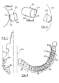
- Figure 1 shows diagrammatically a step-type rotary drill bit for use in drilling deep holes in subsurface formations.
- the drill bit comprises a bit body 10 having a leading face 11 and a gauge region 12.
- the bit body is machined from steel and has a tapered threaded shank 13 for connection to a drill string.
- the leading face 11 of the drill bit is formed with a generally conical recess around which are arranged arrays of PDC cutters arranged in a stepped configuration, in known manner.
- the outer peripheral surface of the leading face of the bit body is generally conical in shape and has part-circular PDC cutters mounted on it in a stepped configuration.
- each PDC cutter comprises a cutting table of polycrystalline diamond bonded to a substrate of cemented tungsten carbide.
- the substrate is either mounted directly in a socket in the body or is brazed to a post or stud which is, in turn, received in a socket in the bit body.
- each cutter is part-circular and has a generally vertical straight cutting edge 14 which bears laterally on the surface of the formation 15 and a horizontal cutting edge 16 which bears downwardly on the formation.
- the cutting elements bearing laterally outwardly against the formation are indicated at 17 and the cutting elements bearing inwardly on a central conical formation 18 on the bottom of the borehole are indicated at 19.
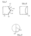
- Figure 2 is a horizontal section through one of the cutting elements 19 which bears against the formation in the central conical projection 18 on the bottom of the borehole.
- the cutter 19 is so orientated on the bit body as to exhibit negative side rake. That is to say, the cutting face 20 of the cutter, as viewed along the longitudinal axis of the bit, is inclined forwardly in the normal direction of rotation of the bit (indicated by the arrow 21) as it extends away from the formation 18.
- the negative side rake angle a is the angle between the cutting face 20 and a radial plane 22 at right angles to the formation 18.
- Figure 3 is a vertical section through the cutter 19 and it will be seen that the cutter is so orientated on the bit body as to exhibit negative top rake, i.e. the cutting face 20 ofthe cutter, as viewed along a radius of the bit, is inclined forwardly in the normal direction of rotation of the bit (indicated by the arrow 21) as it extends away from the formation 18.
- the negative top rake angle ⁇ is the angle between the cutting face 20 and the radial plane 22 at right angles to the formation.
- the negative side rake angle is preferably greater than 20° and, as will be described below, may be as great as 90°.
- the negative top rake angle is preferably at least 20°.
- the negative side rake and top rake may also be applied to outwardly directed cutters and this may be done, not only in a drill bit of the configuration shown in Figure 1, but also in drill bits where the cutting profile is not formed with a central conical depression.
- Figure 4 is a similar view to Figure 2 of an alternative construction.
- the cutter 23 is formed with two cutting faces 24, 25 arranged at an angle to one another. Both cutting faces comprise parts of a cutting table of polycrystalline diamond bonded to a tungsten carbide substrate 26.
- the cutter 23 is so orientated on the bit body that the leading cutting face 24 has a negative side rake angle of approximately 20° or more, whereas the trailing cutting face 25 has a negative side rake angle of substantially 90°. That is to say, the cutting face 25 is arranged substantially tangentially to the curved surface of the formation 27. In this case, therefore, the cutter has very little lateral cutting effect on the formation 27 and performs largely a "bearing" function whereby the engagement of the cutter with the formation tends to stabilise the bit in the borehole.
- the cutter 23 is shown in perspective in Figure 5.
- Figures 4-6 show only one form of cutter having two angled cutting faces and it will be appreciated that other configurations may be employed. Also, the two cutting faces at different side rake angles may be provided on entirely separate cutters located at different places around the leading face of the drill bit. The combined effect of the separate cutters will however be substantially the same as the cutter shown in Figures 4-6.
- the stability of the drill bit in the borehole will be substantially enhanced, and the enhancement may be sufficient to enable the conventional gauge region of the drill bit to be dispensed with.
- a drill bit without such a gauge section is shown diagrammatically in Figure 7.
- the cutters 30, 30A mounted on the bit body 31 around the outer periphery of the drill bit are so orientated as to exhibit negative side rake and negative top rake, as previously described. This applies to the cutters 30 mounted on a generally conical lower part of the bit body as well as to other cutters 30A mounted on a generally cylindrical part of the bit body 31 above the cutters 30.
- Figure 8 illustrates diagrammatically another aspect of the present invention and is a conventional diagrammatic representation showing the relative disposition of cutters on a drill bit in a manner to illustrate the cutting profile.
- the cutters shown diagrammatically in Figure 8 are actually distributed in different locations over the bit body but Figure 8 shows their relative radial and vertical positions to form the cutting profile.
- the cutting profile is partly defined by five inner part-circular cutters 32 arranged in a generally conical pattern over the bit body so as to form an inner frusto-conical upstanding core or projection from the bottom of the borehole being drilled.
- Outwardly of the cutters 32 is a series of circular cutters 33 which form the lowermost part of the borehole bottom.
- Radially outwardly of the cutters 33 is another series of part-circular cutters 34.
- the outer cutters 36 comprise four primary cutters 37 which perform the initial cutting of the formation. However, associated with each primary cutter 37 are one or more back-up cutters 38 which are positioned at substantially the same radial distance from the axis 35 of the bit but are displaced vertically with respect to the primary cutter. The number of back-up cutters increases from one with the two innermost primary cutters to three with the outermost primary cutter 37, the multiple back-up cutters being arranged at different vertical spacings from the primary cutter.
- the radial spacing of the outer cutters 36 is somewhat greater than is normally the case with prior art drill bits and this allows these outer cutters to achieve greater and hence more efficient depth of cut. Although this leads to more rapid wear of the primary cutters, the associated back-up cutters 38 come into play as each primary cutter fails so as to continue cutting the formation at a large and hence efficient depth of cut.
- Figure 8 is particularly suitable for use with the stabilising arrangements previously described, however the back-up cutter arrangement may also be provided with prior art drill bits where the stability of the drill bit in a borehole is effected by other means.
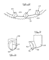
- FIGs 9 to 11 illustrate a modified version of the cutter of Figures 4 to 6, the cutter being of a type to provide increased resistance to impact damage.
- the cutter comprises a generally cylindrical circular cross-section substrate 41 formed, for example, from cemented tungsten carbide. One end of the substrate is formed with two oppositely inclined surfaces 42, 43 arranged at an angle of 120° to one another. Bonded across the surfaces 42, 43 is a facing table 44 of polycrystalline diamond which extends over the ridge 45 between the surfaces 42 and 43.
- the facing table 44 provides two inclined facing surfaces 46 and 47.
- the cutter of Figures 9 to 11 is mounted on the drill bit in similar manner to that shown in Figure 4 or Figure 6 so that one of the faces 46, 47 bears substantially tangentially against the formation while the other face is disposed at a back rake angle of approximately 30°.
- One or both of the front faces 46, 47 is cylindrically curved about an axis parallel to the forwardly facing ridge 45 of the cutter.
- the radius of curvature of the curved surface is approximately equal to the distance of the surface from the central axis of rotation of the drill bit so that the surface is of substantially corresponding curvature to the surface of the gauge pad on which it is mounted. This tends to reduce the abrasive effect of the surface on the formation which it engages and also reduces the susceptibility of the cutter to damage by impact.
- the lower end of the ridge 45 of the cutter is radiused as indicated at 48 in Figures 10 and 11.
- plough cutters 49 are mounted on the bit body 50 around the lowermost annular nose portion of a crown bit. As indicated diagrammatically in Figure 12, the plough cutters create V-section annular grooves 51 in the formation 52 at the bottom of the borehole and, due to their shape, the grooves tend to keep the plough cutters in an annular path thus enhancing the lateral stability of the bit.
- plough cutters are used on the flanks of the bit body they have the effect of cutting a "screw thread" in the formation, which may also enhance the axial stability of the bit.
- FIGS 13 and 14 show a typical plough cutter in greater detail.
- the cutter comprises a tapered tungsten carbide substrate 53 to which is bonded a polycrystalline diamond facing table 54, the substrate being so shaped that the facing table 54, which is of constant thickness, provides a cutting face which comprises two cutting surfaces 55, 56 which are symmetrically arranged on opposite sides of a central forwardly facing ridge 57.
- the cutter is bonded, for example by brazing, to a post 58 which is secured within a socket in the bit body.
Claims (18)
- Trépan de forage rotatif comprenant un corps de trépan (10) comportant une queue (13) destinée à être connectée à un train de tiges, plusieurs éléments de coupe (17, 19) montés sur le corps du trépan, chaque élément de coupe comportant une face de coupe (20) et un moyen pour amener du fluide de forage vers la surface du corps du trépan, pour refroidir et nettoyer les éléments de coupe, au moins certains desdits éléments de coupe (17, 19) étant des éléments de coupe latéraux agencés de sorte à agir latéralement, par rapport à l'axe longitudinal central du trépan de forage, sur la formation en cours de forage, les faces de coupe (20) d'au moins certains desdits éléments de coupe latéraux étant orientés de sorte à présenter une inclinaison latérale négative et une inclinaison vers le haut négative par rapport à la surface de la formation, et caractérisé en ce que les faces de coupe (20) desdits au moins certains éléments de coupe latéraux sont pratiquement plates et en ce que les surfaces de coupe des différents éléments de coupe latéraux (24, 25) s'engageant dans la formation ont des angles d'inclinaison latérale négative différents.
- Trépan de forage selon la revendication 1, caractérisé en ce que l'angle d'inclinaison latérale négative est supérieur à 20°.
- Trépan de forage selon la revendication 1, caractérisé en ce que l'angle d'inclinaison latérale négative correspond à 60°.
- Trépan de forage selon la revendication 1, caractérisé en ce que l'angle d'inclinaison latérale négative correspond à 90°.
- Trépan de forage selon la revendication 1, caractérisé en ce qu'au moins un seul élément de coupe (23) englobe deux faces de coupe (24, 25) formant des angles d'inclinaison latérale négative différents.
- Trépan de forage selon la revendication 5, caractérisé en ce que le seul élément de coupe (23) comprend un substrat généralement cylindrique (26) comportant au niveau d'une extrémité deux surfaces à inclinaison opposée (24, 25) se rencontrant le long d'une nervure, une table de dressage en diamant polycristlallin ou en un autre matériau superdur étant reliée aux dites surfaces du substrat et s'étendant en continu au-dessus de la nervure.
- Trépan de forage selon la revendication 6, caractérisé en ce que l'angle entre les surfaces (24, 25) correspond à environ 120°, de sorte lorsque l'une des surfaces (25) est agencée de manière pratiquement tangentielle par rapport à la surface (27, 29) du corps du trépan, l'autre surface (24) de l'élément de coupe forme un angle d'inclinaison arrière de l'ordre de 30°.
- Trépan de forage selon les revendications 6 ou 7, caractérisé en ce qu'au moins une desdites surfaces (46, 47) est courbée de manière cylindrique autour d'un axe parallèle à ladite nervure (45), le rayon de courbure correspondant pratiquement à la distance radiale entre la surface (46, 47) et l'axe central longitudinal du trépan de forage sur lequel l'élément de coupe est monté en service.
- Trépan de forage selon l'une quelconque des revendications 6 à 8, caractérisé en ce que la nervure (45) traverse l'axe central longitudinal du substrat (41) et s'étend à angle droit par rapport à celui-ci.
- Trépan de forage selon l'une quelconque des revendications 6 à 9, caractérisé en ce que les deux surfaces (46, 47) sont agencées de manière pratiquement symétrique sur chaque côté de la nervure (45).
- Trépan de forage selon l'une quelconque des revendications 6 à 10, caractérisé en ce que la jonction (48) entre au moins une extrémité de la nervure (45) et la surface externe du substrat (41) a une courbure lisse.
- Trépan de forage selon l'une quelconque des revendications 6 à 11, caractérisé en ce que l'angle d'inclinaison négative vers le haut des éléments de coupe latéraux correspond au moins à 20°.
- Trépan de forage selon l'une quelconque des revendications précédentes, caractérisé en ce qu'au moins certains desdits éléments de coupe latéraux (19) sont agencés sur le profil de coupe du trépan de forage de sorte à être supportés vers l'intérieur contre un noyau central (18) de la formation s'étendant vers le haut à partir du fond du trou de forage.
- Trépan de forage selon l'une quelconque des revendications précédentes, caractérisé en ce qu'au moins certains desdits éléments de coupe latéraux (17) sont agencés sur le profil de coupe du trépan de forage de sorte à être supportés vers l'extérieur contre la formation (15) formant les côtés du trou de forage.
- Trépan de forage selon l'une quelconque des revendications précédentes, caractérisé en ce que les éléments de coupe latéraux (17, 19) sont agencés dans une configuration étagée, les éléments de coupe adjacents étant déplacés radialement et axialement les uns par rapport aux autres, par rapport à l'axe longitudinal du trépan de forage.
- Trépan de forage selon l'une quelconque des revendications précédentes, caractérisé en ce que plusieurs éléments de coupe de rabotage (49) sont en plus montés sur le corps du trépan, au niveau de la région avant correspondante ou en un point adjacent à celle-ci, chacun des ces éléments de coupe comprenant deux faces de coupe (55, 56) se rencontrant au niveau d'une nervure orientée vers l'avant (57).
- Trépan de forage selon l'une quelconque des revendications précédentes, caractérisé en ce que le trépan ne comporte pas de section de front de taille passive, la stabilité latérale et en rotation du trépan de forage étant ainsi assurée en service uniquement par l'engagement entre les éléments de coupe (30, 30A) et la formation, aucune partie de la périphérie supportée sur la formation n'étant exempte d'éléments de coupe.
- Trépan de forage selon l'une quelconque des revendications précédentes, caractérisé en ce que chaque élément de coupe (17, 19, 23, 30, 30A, 41) est un élément d'ébauche de coupe PDC comprenant une plaque, par exemple circulaire ou en partie circulaire, composée d'une table superdure de diamant polycristallin établissant la face de coupe avant de l'élément, liée à un substrat composé d'un matériau moins dur, par exemple de carbure de tungstène cimenté.
Priority Applications (1)
| Application Number | Priority Date | Filing Date | Title |
|---|---|---|---|
| EP01113872A EP1134355A3 (fr) | 1994-10-15 | 1995-09-29 | Trépan de forage rotatif |
Applications Claiming Priority (4)
| Application Number | Priority Date | Filing Date | Title |
|---|---|---|---|
| GB9420839 | 1994-10-15 | ||
| GB9420839A GB9420839D0 (en) | 1994-10-15 | 1994-10-15 | Improvements in or relating to rotary drill bits |
| GB9505923 | 1995-03-23 | ||
| GBGB9505923.4A GB9505923D0 (en) | 1995-03-23 | 1995-03-23 | Improvements in or relating to rotary drill bits |
Related Child Applications (1)
| Application Number | Title | Priority Date | Filing Date |
|---|---|---|---|
| EP01113872A Division EP1134355A3 (fr) | 1994-10-15 | 1995-09-29 | Trépan de forage rotatif |
Publications (3)
| Publication Number | Publication Date |
|---|---|
| EP0707130A2 EP0707130A2 (fr) | 1996-04-17 |
| EP0707130A3 EP0707130A3 (fr) | 1997-07-02 |
| EP0707130B1 true EP0707130B1 (fr) | 2003-07-16 |
Family
ID=26305819
Family Applications (1)
| Application Number | Title | Priority Date | Filing Date |
|---|---|---|---|
| EP95306936A Expired - Lifetime EP0707130B1 (fr) | 1994-10-15 | 1995-09-29 | Trépan de forage rotatif |
Country Status (3)
| Country | Link |
|---|---|
| US (1) | US5649604A (fr) |
| EP (1) | EP0707130B1 (fr) |
| DE (1) | DE69531277T2 (fr) |
Families Citing this family (45)
| Publication number | Priority date | Publication date | Assignee | Title |
|---|---|---|---|---|
| US5864058A (en) * | 1994-09-23 | 1999-01-26 | Baroid Technology, Inc. | Detecting and reducing bit whirl |
| US6571891B1 (en) | 1996-04-17 | 2003-06-03 | Baker Hughes Incorporated | Web cutter |
| US5803196A (en) * | 1996-05-31 | 1998-09-08 | Diamond Products International | Stabilizing drill bit |
| US6412580B1 (en) | 1998-06-25 | 2002-07-02 | Baker Hughes Incorporated | Superabrasive cutter with arcuate table-to-substrate interfaces |
| US6527069B1 (en) | 1998-06-25 | 2003-03-04 | Baker Hughes Incorporated | Superabrasive cutter having optimized table thickness and arcuate table-to-substrate interfaces |
| US6536543B2 (en) | 2000-12-06 | 2003-03-25 | Baker Hughes Incorporated | Rotary drill bits exhibiting sequences of substantially continuously variable cutter backrake angles |
| US7036611B2 (en) | 2002-07-30 | 2006-05-02 | Baker Hughes Incorporated | Expandable reamer apparatus for enlarging boreholes while drilling and methods of use |
| US7461709B2 (en) * | 2003-08-21 | 2008-12-09 | Smith International, Inc. | Multiple diameter cutting elements and bits incorporating the same |
| US20050247486A1 (en) * | 2004-04-30 | 2005-11-10 | Smith International, Inc. | Modified cutters |
| US7243745B2 (en) * | 2004-07-28 | 2007-07-17 | Baker Hughes Incorporated | Cutting elements and rotary drill bits including same |
| GB0521693D0 (en) * | 2005-10-25 | 2005-11-30 | Reedhycalog Uk Ltd | Representation of whirl in fixed cutter drill bits |
| US20070278014A1 (en) * | 2006-05-30 | 2007-12-06 | Smith International, Inc. | Drill bit with plural set and single set blade configuration |
| US8899352B2 (en) | 2007-08-15 | 2014-12-02 | Schlumberger Technology Corporation | System and method for drilling |
| US7971661B2 (en) | 2007-08-15 | 2011-07-05 | Schlumberger Technology Corporation | Motor bit system |
| US8534380B2 (en) | 2007-08-15 | 2013-09-17 | Schlumberger Technology Corporation | System and method for directional drilling a borehole with a rotary drilling system |
| US8066085B2 (en) | 2007-08-15 | 2011-11-29 | Schlumberger Technology Corporation | Stochastic bit noise control |
| US8763726B2 (en) * | 2007-08-15 | 2014-07-01 | Schlumberger Technology Corporation | Drill bit gauge pad control |
| US8720604B2 (en) * | 2007-08-15 | 2014-05-13 | Schlumberger Technology Corporation | Method and system for steering a directional drilling system |
| US8757294B2 (en) * | 2007-08-15 | 2014-06-24 | Schlumberger Technology Corporation | System and method for controlling a drilling system for drilling a borehole in an earth formation |
| BRPI0911638B1 (pt) * | 2008-04-23 | 2019-03-26 | Baker Hughes Incorporated | Métodos, sistemas e composições de fundo que incluem um escareador com saídas traseiras efetivas variáveis |
| US8833492B2 (en) * | 2008-10-08 | 2014-09-16 | Smith International, Inc. | Cutters for fixed cutter bits |
| US8584776B2 (en) * | 2009-01-30 | 2013-11-19 | Baker Hughes Incorporated | Methods, systems, and tool assemblies for distributing weight between an earth-boring rotary drill bit and a reamer device |
| US8505634B2 (en) * | 2009-12-28 | 2013-08-13 | Baker Hughes Incorporated | Earth-boring tools having differing cutting elements on a blade and related methods |
| CA2788816C (fr) * | 2010-02-05 | 2015-11-24 | Baker Hughes Incorporated | Elements de coupe profiles sur des trepans et autres outils de forage, et procedes de formation de tels elements |
| US8851207B2 (en) | 2011-05-05 | 2014-10-07 | Baker Hughes Incorporated | Earth-boring tools and methods of forming such earth-boring tools |
| SA111320671B1 (ar) | 2010-08-06 | 2015-01-22 | بيكر هوغيس انكور | عوامل القطع المشكلة لادوات ثقب الارض و ادوات ثقب الارض شاملة عوامل القطع هذه و الطرق المختصة بها |
| US9739097B2 (en) | 2011-04-26 | 2017-08-22 | Smith International, Inc. | Polycrystalline diamond compact cutters with conic shaped end |
| WO2012149120A2 (fr) | 2011-04-26 | 2012-11-01 | Smith International, Inc. | Procédés de fixation de lames roulantes dans des outils à lames fixes au moyen d'un manchon, d'un ressort de compression et/ou d'une ou plusieurs goupilles/billes |
| US9371699B2 (en) | 2011-10-26 | 2016-06-21 | Baker Hughes Incorporated | Plow-shaped cutting elements for earth-boring tools, earth-boring tools including such cutting elements, and related methods |
| EP2812523B1 (fr) | 2012-02-08 | 2019-08-07 | Baker Hughes, a GE company, LLC | Éléments de coupe profilés pour outils de forage et outils de forage comprenant lesdits éléments de coupe |
| RU2515795C2 (ru) * | 2012-03-12 | 2014-05-20 | Станислав Васильевич Синев | Буровое шарошечное долото |
| US9151120B2 (en) * | 2012-06-04 | 2015-10-06 | Baker Hughes Incorporated | Face stabilized downhole cutting tool |
| RU2541994C2 (ru) * | 2012-11-08 | 2015-02-20 | Станислав Васильевич Синев | Ступенчатый лопастной pdc-инструмент |
| CA2892600C (fr) | 2012-12-03 | 2020-09-22 | Ulterra Drilling Technologies, L.P. | Outil de forage de terre presentant un agencement ameliore d'inclinaisons laterales de dispositif de coupe |
| WO2014186212A1 (fr) | 2013-05-16 | 2014-11-20 | Us Synthetic Corporation | Système d'élimination de revêtement de route faisant intervenir des agrégats de diamant polycristallin |
| US10323514B2 (en) | 2013-05-16 | 2019-06-18 | Us Synthetic Corporation | Shear cutter pick milling system |
| US10414069B2 (en) | 2014-04-30 | 2019-09-17 | Us Synthetic Corporation | Cutting tool assemblies including superhard working surfaces, material-removing machines including cutting tool assemblies, and methods of use |
| US10408057B1 (en) | 2014-07-29 | 2019-09-10 | Apergy Bmcs Acquisition Corporation | Material-removal systems, cutting tools therefor, and related methods |
| US10648330B1 (en) | 2015-09-25 | 2020-05-12 | Us Synthetic Corporation | Cutting tool assemblies including superhard working surfaces, cutting tool mounting assemblies, material-removing machines including the same, and methods of use |
| WO2017087920A1 (fr) * | 2015-11-19 | 2017-05-26 | Smith International, Inc. | Trépans à molettes fixes et autres outils en profondeur de forage sur lesquels se trouvent des éléments de coupe non plans |
| US11480016B2 (en) | 2018-11-12 | 2022-10-25 | Ulterra Drilling Technologies, L.P. | Drill bit |
| USD924949S1 (en) | 2019-01-11 | 2021-07-13 | Us Synthetic Corporation | Cutting tool |
| WO2020180330A1 (fr) * | 2019-03-07 | 2020-09-10 | Halliburton Energy Services, Inc. | Agencements de haveuse de forme |
| EP3757344A1 (fr) | 2019-06-25 | 2020-12-30 | VAREL EUROPE (Société par Actions Simplifiée) | Foret doté d'un effet de réduction de poids sur bit |
| WO2021059034A1 (fr) * | 2019-09-27 | 2021-04-01 | Varel International Ind., L.L.C. | Pince-gouge en forme de griffe à angle élevé pour trépan à coupe fixe |
Family Cites Families (27)
| Publication number | Priority date | Publication date | Assignee | Title |
|---|---|---|---|---|
| US3635296A (en) * | 1970-06-04 | 1972-01-18 | Maurice P Lebourg | Drill bit construction |
| US3640355A (en) * | 1970-06-04 | 1972-02-08 | Maurice P Lebourg | Drill bit |
| US4086973A (en) * | 1976-12-03 | 1978-05-02 | Dresser Industries, Inc. | Asymmetric insert for inner row of an earth boring cutter |
| DE2719330C3 (de) * | 1977-04-30 | 1984-01-05 | Christensen, Inc., 84115 Salt Lake City, Utah | Drehbohrmeißel |
| US4140189A (en) * | 1977-06-06 | 1979-02-20 | Smith International, Inc. | Rock bit with diamond reamer to maintain gage |
| US4244432A (en) * | 1978-06-08 | 1981-01-13 | Christensen, Inc. | Earth-boring drill bits |
| US4351401A (en) * | 1978-06-08 | 1982-09-28 | Christensen, Inc. | Earth-boring drill bits |
| US4373593A (en) * | 1979-03-16 | 1983-02-15 | Christensen, Inc. | Drill bit |
| GB2060735B (en) * | 1979-10-16 | 1983-06-22 | Christensen Inc | Diamond drill bits for drilling bore holes in earth formations |
| ZA806249B (en) * | 1979-11-19 | 1982-01-27 | Gen Electric | Compacts for diamond drill and saw applications |
| US4586574A (en) * | 1983-05-20 | 1986-05-06 | Norton Christensen, Inc. | Cutter configuration for a gage-to-shoulder transition and face pattern |
| US4602691A (en) * | 1984-06-07 | 1986-07-29 | Hughes Tool Company | Diamond drill bit with varied cutting elements |
| GB8418481D0 (en) * | 1984-07-19 | 1984-08-22 | Nl Petroleum Prod | Rotary drill bits |
| US4819516A (en) * | 1988-01-07 | 1989-04-11 | Diamant Boart-Stratabit (Usa) Inc. | Method of forming a cutting element having a V-shaped diamond cutting face |
| GB2218131B (en) * | 1988-05-06 | 1992-03-25 | Reed Tool Co | Improvements in or relating to rotary drill bits |
| US4858707A (en) * | 1988-07-19 | 1989-08-22 | Smith International, Inc. | Convex shaped diamond cutting elements |
| US4932484A (en) * | 1989-04-10 | 1990-06-12 | Amoco Corporation | Whirl resistant bit |
| GB8926688D0 (en) * | 1989-11-25 | 1990-01-17 | Reed Tool Co | Improvements in or relating to rotary drill bits |
| SE9002137D0 (sv) * | 1990-06-15 | 1990-06-15 | Diamant Boart Stratabit Sa | Improved tools for cutting rock drilling |
| US5199511A (en) * | 1991-09-16 | 1993-04-06 | Baker-Hughes, Incorporated | Drill bit and method for reducing formation fluid invasion and for improved drilling in plastic formations |
| EP0536762B1 (fr) * | 1991-10-09 | 1997-09-03 | Smith International, Inc. | Elément de coupe rapporté en diamant avec une surface de coupe convexe |
| US5265685A (en) | 1991-12-30 | 1993-11-30 | Dresser Industries, Inc. | Drill bit with improved insert cutter pattern |
| US5282513A (en) * | 1992-02-04 | 1994-02-01 | Smith International, Inc. | Thermally stable polycrystalline diamond drill bit |
| US5303785A (en) * | 1992-08-25 | 1994-04-19 | Smith International, Inc. | Diamond back-up for PDC cutters |
| GB2273946B (en) * | 1992-12-31 | 1996-10-09 | Camco Drilling Group Ltd | Improvements in or relating to rotary drill bits |
| GB9314954D0 (en) * | 1993-07-16 | 1993-09-01 | Camco Drilling Group Ltd | Improvements in or relating to torary drill bits |
| US5549171A (en) * | 1994-08-10 | 1996-08-27 | Smith International, Inc. | Drill bit with performance-improving cutting structure |
-
1995
- 1995-09-29 DE DE69531277T patent/DE69531277T2/de not_active Expired - Fee Related
- 1995-09-29 EP EP95306936A patent/EP0707130B1/fr not_active Expired - Lifetime
- 1995-10-03 US US08/538,759 patent/US5649604A/en not_active Expired - Lifetime
Also Published As
| Publication number | Publication date |
|---|---|
| EP0707130A3 (fr) | 1997-07-02 |
| DE69531277D1 (de) | 2003-08-21 |
| DE69531277T2 (de) | 2004-05-19 |
| US5649604A (en) | 1997-07-22 |
| EP0707130A2 (fr) | 1996-04-17 |
Similar Documents
| Publication | Publication Date | Title |
|---|---|---|
| EP0707130B1 (fr) | Trépan de forage rotatif | |
| US5119892A (en) | Notary drill bits | |
| US5186268A (en) | Rotary drill bits | |
| US5531281A (en) | Rotary drilling tools | |
| US5979577A (en) | Stabilizing drill bit with improved cutting elements | |
| EP0884449B1 (fr) | Trépan de forage rotatif | |
| US5873422A (en) | Anti-whirl drill bit | |
| US6408958B1 (en) | Superabrasive cutting assemblies including cutters of varying orientations and drill bits so equipped | |
| US6439326B1 (en) | Centered-leg roller cone drill bit | |
| US5467836A (en) | Fixed cutter bit with shear cutting gage | |
| US6779613B2 (en) | Drill bits with controlled exposure of cutters | |
| US9016407B2 (en) | Drill bit cutting structure and methods to maximize depth-of-cut for weight on bit applied | |
| US6050354A (en) | Rolling cutter bit with shear cutting gage | |
| EP0710765B1 (fr) | Perfectionnements relatifs aux trépans de forage rotatifs | |
| EP0418706B1 (fr) | Trépan de forage pour formations dures et tendres | |
| EP0546725B1 (fr) | Eléments de coupe pour trépan | |
| US5346026A (en) | Rolling cone bit with shear cutting gage | |
| US5611649A (en) | Elements faced with superhard material | |
| US5607025A (en) | Drill bit and cutting structure having enhanced placement and sizing of cutters for improved bit stabilization | |
| US5816346A (en) | Rotary drill bits and methods of designing such drill bits | |
| CA1214159A (fr) | Trepan de forage et organe de coupe perfectionne | |
| EP0707131B1 (fr) | Trépan de forage rotatif avec section de calibre montée de façon mobile pour la stabilisation du trépan | |
| US6105693A (en) | Partially enhanced percussive drill bit | |
| US4928777A (en) | Cutting elements for rotary drill bits | |
| GB2294069A (en) | Rotary drill bits |
Legal Events
| Date | Code | Title | Description |
|---|---|---|---|
| PUAI | Public reference made under article 153(3) epc to a published international application that has entered the european phase |
Free format text: ORIGINAL CODE: 0009012 |
|
| AK | Designated contracting states |
Kind code of ref document: A2 Designated state(s): BE DE FR IE |
|
| PUAL | Search report despatched |
Free format text: ORIGINAL CODE: 0009013 |
|
| AK | Designated contracting states |
Kind code of ref document: A3 Designated state(s): BE DE FR IE |
|
| 17P | Request for examination filed |
Effective date: 19971217 |
|
| 17Q | First examination report despatched |
Effective date: 20010208 |
|
| GRAH | Despatch of communication of intention to grant a patent |
Free format text: ORIGINAL CODE: EPIDOS IGRA |
|
| GRAH | Despatch of communication of intention to grant a patent |
Free format text: ORIGINAL CODE: EPIDOS IGRA |
|
| GRAA | (expected) grant |
Free format text: ORIGINAL CODE: 0009210 |
|
| AK | Designated contracting states |
Designated state(s): BE DE FR IE |
|
| REG | Reference to a national code |
Ref country code: IE Ref legal event code: FG4D |
|
| REF | Corresponds to: |
Ref document number: 69531277 Country of ref document: DE Date of ref document: 20030821 Kind code of ref document: P |
|
| ET | Fr: translation filed | ||
| PLBE | No opposition filed within time limit |
Free format text: ORIGINAL CODE: 0009261 |
|
| STAA | Information on the status of an ep patent application or granted ep patent |
Free format text: STATUS: NO OPPOSITION FILED WITHIN TIME LIMIT |
|
| 26N | No opposition filed |
Effective date: 20040419 |
|
| PGFP | Annual fee paid to national office [announced via postgrant information from national office to epo] |
Ref country code: FR Payment date: 20050823 Year of fee payment: 11 |
|
| PGFP | Annual fee paid to national office [announced via postgrant information from national office to epo] |
Ref country code: IE Payment date: 20050913 Year of fee payment: 11 |
|
| PGFP | Annual fee paid to national office [announced via postgrant information from national office to epo] |
Ref country code: DE Payment date: 20050922 Year of fee payment: 11 |
|
| PGFP | Annual fee paid to national office [announced via postgrant information from national office to epo] |
Ref country code: BE Payment date: 20051123 Year of fee payment: 11 |
|
| PG25 | Lapsed in a contracting state [announced via postgrant information from national office to epo] |
Ref country code: IE Free format text: LAPSE BECAUSE OF NON-PAYMENT OF DUE FEES Effective date: 20060929 |
|
| PG25 | Lapsed in a contracting state [announced via postgrant information from national office to epo] |
Ref country code: BE Free format text: LAPSE BECAUSE OF NON-PAYMENT OF DUE FEES Effective date: 20060930 |
|
| PG25 | Lapsed in a contracting state [announced via postgrant information from national office to epo] |
Ref country code: DE Free format text: LAPSE BECAUSE OF NON-PAYMENT OF DUE FEES Effective date: 20070403 |
|
| REG | Reference to a national code |
Ref country code: IE Ref legal event code: MM4A |
|
| REG | Reference to a national code |
Ref country code: FR Ref legal event code: ST Effective date: 20070531 |
|
| BERE | Be: lapsed |
Owner name: *CAMCO DRILLING GROUP LTD Effective date: 20060930 |
|
| PG25 | Lapsed in a contracting state [announced via postgrant information from national office to epo] |
Ref country code: FR Free format text: LAPSE BECAUSE OF NON-PAYMENT OF DUE FEES Effective date: 20061002 |