EP0706960B1 - Device for order picking of articles - Google Patents
Device for order picking of articles Download PDFInfo
- Publication number
- EP0706960B1 EP0706960B1 EP95810619A EP95810619A EP0706960B1 EP 0706960 B1 EP0706960 B1 EP 0706960B1 EP 95810619 A EP95810619 A EP 95810619A EP 95810619 A EP95810619 A EP 95810619A EP 0706960 B1 EP0706960 B1 EP 0706960B1
- Authority
- EP
- European Patent Office
- Prior art keywords
- belt
- objects
- transfer device
- entrance
- exit
- Prior art date
- Legal status (The legal status is an assumption and is not a legal conclusion. Google has not performed a legal analysis and makes no representation as to the accuracy of the status listed.)
- Expired - Lifetime
Links
- 239000000853 adhesive Substances 0.000 claims abstract description 9
- 230000001070 adhesive effect Effects 0.000 claims abstract description 9
- 230000004888 barrier function Effects 0.000 claims description 17
- 238000000034 method Methods 0.000 claims description 10
- 238000009434 installation Methods 0.000 claims 11
- 238000005259 measurement Methods 0.000 claims 1
- 238000000605 extraction Methods 0.000 abstract 1
- 238000011161 development Methods 0.000 description 3
- 230000018109 developmental process Effects 0.000 description 3
- 230000000052 comparative effect Effects 0.000 description 1
- 230000001419 dependent effect Effects 0.000 description 1
- 235000013399 edible fruits Nutrition 0.000 description 1
- 235000021485 packed food Nutrition 0.000 description 1
Images


Classifications
-
- B—PERFORMING OPERATIONS; TRANSPORTING
- B65—CONVEYING; PACKING; STORING; HANDLING THIN OR FILAMENTARY MATERIAL
- B65G—TRANSPORT OR STORAGE DEVICES, e.g. CONVEYORS FOR LOADING OR TIPPING, SHOP CONVEYOR SYSTEMS OR PNEUMATIC TUBE CONVEYORS
- B65G47/00—Article or material-handling devices associated with conveyors; Methods employing such devices
- B65G47/22—Devices influencing the relative position or the attitude of articles during transit by conveyors
- B65G47/26—Devices influencing the relative position or the attitude of articles during transit by conveyors arranging the articles, e.g. varying spacing between individual articles
- B65G47/30—Devices influencing the relative position or the attitude of articles during transit by conveyors arranging the articles, e.g. varying spacing between individual articles during transit by a series of conveyors
- B65G47/31—Devices influencing the relative position or the attitude of articles during transit by conveyors arranging the articles, e.g. varying spacing between individual articles during transit by a series of conveyors by varying the relative speeds of the conveyors forming the series
Definitions
- the registration concerns a system for picking Objects that are connected by a large number of articulated, a carriage with a laterally tiltable support plate a conveyor line arranged approximately at right angles to it Discharge device are fed, the in the conveying direction the objects to be discharged inclined downwards arranged discharge device at an entrance with the objects tipped by the wagons and can be loaded on one Output from the objects is unloadable.
- EP-A-0 540 464 discloses a plant for sorting General cargo or for picking objects that by means of a plurality of articulated ones, one Carriage with tilting support plate on one side Conveyor line of a discharge device arranged approximately at right angles to it are fed, which discharge device at an entrance with those tipped over by the cars Objects loadable and at an exit from the objects is unloadable, the discharge device referred to as a slide between entrance and exit in the conveying direction the objects to be discharged inclined downwards is arranged.
- the invention has for its object a system of to create the type mentioned, at least one of the above Avoids difficulties.
- the task is in a generic system solved that the ejection device in front of the exit Has clock tape and in front of this at least one other tape is arranged on which at least one object to be controlled Delivery to the timing belt is positionable.
- the objects are opened the discharge device is thus delivered clocked to a clock belt.
- the objects can then do a great deal on this cycle are gently conveyed downwards one after the other.
- An attack at the bottom of the reject device is not more necessary.
- Even when the clock tape is completely full the objects are not against each other under high pressure, but ordered and loosely next to each other so that they are at the bottom End of the bar or on subsequent roles essential can be removed more easily than before.
- the proportion of damaged Items is much less than before because they do not collide with each other, but individually against the clock tape be handed over.
- the invention also relates to a method for commissioning of objects that are connected by means of a large number of articulated a trolley with a laterally tiltable support plate on a conveyor line arranged approximately at right angles to it Discharge device are supplied, the in Direction of conveyance of the objects to be discharged downwards inclined discharge device at an entrance loadable with the objects tipped over by the wagons and on an outlet is unloadable from the objects, and the between the entrance and exit can be filled with objects.
- this method provides that the objects on the discharge device into a predetermined Position brought and clocked from this position promoted and before the exit in at least one comparative dense row can be arranged for removal.
- the method according to the invention also solves the problem Task.
- By positioning and subsequent clocked Arranging the items it is also possible to determine the degree of filling the objects in the discharge device essential to increase. In particular, it is possible to place the objects side by side to position and thus at least a double Form a series of objects.
- a particularly efficient discharge results when, according to a development of the invention, at the entrance a discharge belt is arranged in the discharge device.
- This preferably has a highly adhesive top, so objects thrown on this tape accordingly the running speed of this belt are promoted.
- a brake band runs much slower than the take-off belt.
- the outside the brake band is preferably much less adhesive than that of the trigger tape.
- Be on the brake band thus the objects are braked, preferably to the extent that that they come to a standstill on this.
- One at the end of the Brake belt positioned object can be actuated of the clock tape are recorded on this.
- the control the cycle band is preferably carried out by a light barrier, with which the presence of an object on End of the brake band is noticeable.
- the light barrier can also determine the length of the object and move the clock tape accordingly. With a long one The subject is the clock tape for its recording moved longer than to take a shorter object. This is a particularly efficient and optimal filling the discharge device possible.
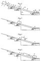
- Figure 1 shows a piece goods conveyor 1, the driven Conveyor train from a variety articulated with each other connected carriage 2, on each of which in one essential horizontal support plate 3 is an object 4 is located, either by tilting the support plate 3 Actuate a backdrop 6 in the direction of arrow 8 or by actuating another backdrop 7 in the direction of Arrow 9 are delivered to a discharge device 10 can.
- General cargo conveyors of this type are well known per se.
- Item 4 is, for example, a box, a deep-frozen one and packaged food, a household item and the same.
- the discharge device 10 has an input 18 which to the side of the conveyor and essentially on the conveyor Height is arranged. At the other end of the discharge device 10 there are several rollers 20, which have an output 19th form to remove the discharged objects 4.
- the Exit 19 is preferably arranged lower than the entrance 18. Between the input 18 and the output 19 are consecutive a trigger belt 11, a brake belt 12 and a timing belt 17th arranged on which the objects 4 from the entrance 18 to Exit 19 are promoted and explained in more detail below become.
- the take-off belt 11 is an endless belt around a drive roller 26 and a pulley 29 placed and by one Motor 23 is driven.
- the outside lla of the trigger tape 11 is comparatively strongly adhesive, such that an object thrown onto the take-off belt 11 on this does not slip and takes on the speed of the belt.
- the speed of the take-off belt 11 is, for example 2 m per second.
- the band 11 and also the other bands are of course on a not shown here Frame 32 attached.
- the brake band 12 closes directly at the end of the trigger band 11 and is also about a drive roller 27 and a deflection roller 30 is placed.
- the drive roller 27 is from driven by a motor 24.
- the tapes 11 and 12 can be by means of of an exaggeration not shown here, however, also from be driven by a single motor.
- the outside 12a the brake band 12 is slidable and thus much less adhesive than the top lla.
- the speed the brake band 12 is much smaller than that of the Trigger tape 11, preferably several times smaller, and is, for example, 0.5 m per second.
- the directions of movement of the two bands 11 and 12 are the same and in the Figure 1 indicated by arrows 13 and 14.
- a light barrier 21 is attached to the side, with the presence of an object 4 at the height this light barrier 21 can be detected. Due to corresponding Signals of the light barrier is not with one here shown control device controls the timing belt 17.
- the timing belt is around a drive roller 28 and placed around a pulley 31 and is driven by a motor 25 driven.
- the clock tape 17 is much longer than that Trigger belt 11 and the brake band 12.
- the outside 17a of the Clock tape 17 is preferably less adhesive than that of the trigger tape 11.
- a further light barrier 22 is arranged, with which the Presence of an object 4 at the end of the clock tape 17th is noticeable.
- the light barriers 21 and 22 can of course also by other suitable barriers, for example mechanically operated barriers can also be replaced.
- Figure 2 shows a carriage 2, the support plate 3 for discharge an object 4 by means of the backdrop 6 or 7 is brought into a predetermined inclined state.
- the inclination of the support plate 3 the object 4 slides in Direction of arrow 8 on the trigger belt 11 and is on this according to the speed of this belt 11 in Figure 2 promoted to the right.
- the adhesive 4 of the tape 11 can accelerate the object 4 become.
- An object projecting laterally from the band 11 4 is formed by funnel-shaped guide walls 11 aligned.
- the trigger belt 11 is preferably permanent and driven at the same speed.
- the object 4 has the lower end of the trigger belt 11 reached, he arrives at the brake band 12, which as mentioned has a comparatively slippery outside 12a and runs much slower than the trigger belt 11.
- the object slips as its speed slows down the tape 12 in the same direction and finally arrives in the position shown in Figure 3.
- the object 4 at the front end on the timing belt 17th that stands still at this time.
- FIG. 6 shows the system 1 with several discharge devices 10. As can be seen, these discharge devices 10 depending on the size of the objects 4 simple or be occupied twice. It is also possible to take turns a single or double occupancy. Of course you can the discharge devices 10 are also only partially filled become. Shown is an operator 33, a transfer device 10 removes an object 4 and one feeds further transport device 34. Because the lowest Objects on the discharge devices 10 free and are not attached to a stop, these objects can each effortlessly gripped and carried away from the rollers 10 become.
Landscapes
- Engineering & Computer Science (AREA)
- Mechanical Engineering (AREA)
- Warehouses Or Storage Devices (AREA)
- Control Of Conveyors (AREA)
- Hydroponics (AREA)
- Structure Of Belt Conveyors (AREA)
- Agricultural Chemicals And Associated Chemicals (AREA)
Abstract
Description
Die Anmeldung betrifft eine Anlage zur Kommissionierung von Gegenständen, die mittels einer Vielzahl gelenkig verbundener, eine seitlich kippbare Tragplatte aufweisenden Wagen auf einem Förderstrang einer etwa rechtwinklig dazu angeordneten Ausschleusvorrichtung zugeführt werden, wobei die in Förderrichtung der auszuschleusenden Gegenstände nach unten geneigt angeordnete Ausschleusvorrichtung an einem Eingang mit den von den Wagen gekippten Gegenständen beladbar und an einem Ausgang von den Gegenständen entladbar ist.The registration concerns a system for picking Objects that are connected by a large number of articulated, a carriage with a laterally tiltable support plate a conveyor line arranged approximately at right angles to it Discharge device are fed, the in the conveying direction the objects to be discharged inclined downwards arranged discharge device at an entrance with the objects tipped by the wagons and can be loaded on one Output from the objects is unloadable.
Anlagen dieser Art werden seit langem in Verteilzentren zur Kommissionierung von in Läden angebotenen Gütern verwendet. In diesen Anlagen werden die Güter einzeln mit einem Förderer in die vorgesehene Ausschleusvorrichtung geworfen und rutschen auf dieser durch ihr Eigengewicht auf einer Rollbahn nach unten gegen einen Anschlag oder einen bereits ausgeschleusten Gegenstand. Die in eine Ausschleusvorrichtung eingebrachten Gegenstände sind in der Regel sehr unterschiedlich, insbesondere bezüglich ihres Gewichtes und ihrer Zerbrechlichkeit. Diese Gegenstände sind besipielsweise verpackte Gläser, Tiefkühlprodukte, Kisten mit Flaschen, verpackte Früchte und verpackte Papeterieprodukte. Zum Entladen der Ausschleusvorrichtung werden jeweils die untersten Gegenstände von Hand der Ausschleusvorrichtung entnommen und einer weiteren Transportvorrichtung, beispielsweise einem Transportband übergeben. Bei diesen bekannten Anlagen bestand die Schwierigkeit, dass empfindliche Gegenstände beim Aufprall auf einen bereits ausgeschleusten Gegenstand oder durch einen nachkommenden Gegenstand oft beschädigt wurden. Als nachteilig wird auch angesehen, dass die untersten Gegenstände oft verklemmt sind und nur mit Mühe entnommen werden konnten. Bei den bekannten Anlagen war somit das Entladen mühsam und der Anteil beschädigter Gegenstände hoch.Systems of this type have long been used in distribution centers Picking of goods offered in stores used. In these plants, the goods are transported individually with a conveyor thrown into the intended discharge device and slide on this due to its own weight on a runway down against a stop or one that has already been removed Object. The placed in a discharge device Items are usually very different, especially regarding their weight and their fragility. These items are packaged, for example Jars, frozen products, boxes with bottles, packaged Fruits and packaged stationery products. To unload the Discharge device are the lowest objects removed by hand from the discharge device and one another transport device, for example a conveyor belt to hand over. In these known systems, the Difficulty being sensitive objects on impact to an object that has already been removed or by a coming object were often damaged. As a disadvantage it is also considered that the bottom items often are jammed and could only be removed with difficulty. At unloading was thus tedious and the known systems High proportion of damaged items.
Die EP-A-0 540 464 offenbart eine Anlage zum Sortieren von Stückgütern oder zur Kommissionierung von Gegenständen, die mittels einer Vielzahl gelenkig miteinander verbundener, eine seitlich kippbare Tragplatte aufweisenden Wagen auf einem Förderstrang einer etwa rechtwinklig dazu angeordneten Ausschleusvorrichtung zugeführt werden, welche Ausschleusvorrichtung an einem Eingang mit den von den Wagen gekippten Gegenständen beladbar und an einem Ausgang von den Gegenständen entladbar ist, wobei die als Rutsche bezeichnete Ausschleusvorrichtung zwischen Eingang und Ausgang in Förderrichtung der auszuschleusenden Gegenstände nach unten geneigt angeordnet ist.EP-A-0 540 464 discloses a plant for sorting General cargo or for picking objects that by means of a plurality of articulated ones, one Carriage with tilting support plate on one side Conveyor line of a discharge device arranged approximately at right angles to it are fed, which discharge device at an entrance with those tipped over by the cars Objects loadable and at an exit from the objects is unloadable, the discharge device referred to as a slide between entrance and exit in the conveying direction the objects to be discharged inclined downwards is arranged.
Der Erfindung liegt die Aufgabe zugrunde, eine Anlage der genannten Art zu schaffen, die wenigstens eine der genannten Schwierigkeiten vermeidet.The invention has for its object a system of to create the type mentioned, at least one of the above Avoids difficulties.
Die Aufgabe ist bei einer gattungsgemässen Anlage dadurch gelöst, dass die Ausschleusvorrichtung vor dem Ausgang ein Taktband aufweist und vor diesem wenigstens ein weiteres Band angeordnet ist, auf dem wenigstens ein Gegenstand zur gesteuerten Abgabe an das Taktband positionierbar ist.The task is in a generic system solved that the ejection device in front of the exit Has clock tape and in front of this at least one other tape is arranged on which at least one object to be controlled Delivery to the timing belt is positionable.
Bei der erfindungsgemässen Anlage werden die Gegenstände auf der Ausschleusvorrichtung somit getaktet an ein Taktband abgegeben. Auf diesem Taktband können dann die Gegenstände sehr schonend hintereinander nach unten gefördert werden. Ein Anschlag am unteren Ende der Ausschleusvorrichtung ist nicht mehr notwendig. Auch bei vollständig gefülltem Taktband liegen die Gegenstände nicht unter hohem Druck aneinander, sondern geordnet und lose nebeneinander, so dass sie am unteren Ende des Taktbandes oder auf nachfolgenden Rollen wesentlich einfacher als bisher entnommen werden können. Der Anteil beschädigter Gegenstände ist wesentlich geringer als bisher, da sie nicht aufeinander prallen, sondern einzeln an das Taktband übergeben werden.In the system according to the invention, the objects are opened the discharge device is thus delivered clocked to a clock belt. The objects can then do a great deal on this cycle are gently conveyed downwards one after the other. An attack at the bottom of the reject device is not more necessary. Even when the clock tape is completely full the objects are not against each other under high pressure, but ordered and loosely next to each other so that they are at the bottom End of the bar or on subsequent roles essential can be removed more easily than before. The proportion of damaged Items is much less than before because they do not collide with each other, but individually against the clock tape be handed over.
Die Erfindung betrifft zudem ein Verfahren zur Kommsissionie- von Gegenständen, die mittels einer Vielzahl gelenkig verbundener, eine seitlich kippbare Tragplatte aufweisenden Wagen auf einem Förderstrang einer etwa rechtwinklig dazu angeordneten Ausschleusvorrichtung zugeführt werden, wobei die in Förderrichtung der auszuschleusenden Gegenstände nach unten geneigt angeordnete Ausschleusvorrichtung an einem Eingang mit den von den Wagen gekippten Gegenständen beladbar und an einem Ausgang von den Gegenständen entladbar ist, und die zwischen Eingang und Ausgang mit Gegenständen füllbar ist. Erfindungsgemäss ist bei diesem Verfahren vorgesehen, dass die Gegenstände auf der Ausschleusvorrichtung in eine vorbestimmte Position gebracht und aus dieser Position getaktet weitergefördert und vor dem Ausgang in wenigstens einer vergleichsweise dichten Reihe zur Entnahme angeordnet werden. The invention also relates to a method for commissioning of objects that are connected by means of a large number of articulated a trolley with a laterally tiltable support plate on a conveyor line arranged approximately at right angles to it Discharge device are supplied, the in Direction of conveyance of the objects to be discharged downwards inclined discharge device at an entrance loadable with the objects tipped over by the wagons and on an outlet is unloadable from the objects, and the between the entrance and exit can be filled with objects. According to the invention, this method provides that the objects on the discharge device into a predetermined Position brought and clocked from this position promoted and before the exit in at least one comparative dense row can be arranged for removal.
Das erfindungsgemässe Verfahren löst ebenfalls die gestellte Aufgabe. Durch die Positionierung und nachfolgende getaktete Anordnung der Gegenstände ist es zudem möglich, den Füllungsgrad der Gegenstände in der Ausschleusvorrichtung wesentlich zu erhöhen. Insbesondere ist es möglich, die Gegenstände nebeneinander zu positionieren und damit wenigstens eine doppelte Reihe von Gegenständen zu bilden.The method according to the invention also solves the problem Task. By positioning and subsequent clocked Arranging the items, it is also possible to determine the degree of filling the objects in the discharge device essential to increase. In particular, it is possible to place the objects side by side to position and thus at least a double Form a series of objects.
Eine besonders leistungsfähige Ausschleusung ergibt sich dann, wenn gemäss einer Weiterbildung der Erfindung am Eingang der Ausschleusvorrichtung ein Abzugsband angeordnet ist. Dieses weist vorzugsweise eine stark adhäsive Oberseite auf, so dass auf dieses Band geworfene Gegenstände entsprechend der Laufgeschwindigkeit dieses Bandes gefördert werden.A particularly efficient discharge results when, according to a development of the invention, at the entrance a discharge belt is arranged in the discharge device. This preferably has a highly adhesive top, so objects thrown on this tape accordingly the running speed of this belt are promoted.
Nach einer Weiterbildung der Erfindung ist vorzugsweise anschliessend an das Abzugsband ein Bremsband angeordnet, das wesentlich langsamer läuft als das Abzugsband. Die Aussenseite des Bremsbandes ist vorzugsweise wesentlich weniger adhäsiv als diejenige des Abzugsbandes. Auf dem Bremsband werden somit die Gegenstände gebremst und zwar vorzugsweise soweit, dass sie auf diesem zum Stillstand kommen. Ein am Ende des Bremsbandes positionierter Gegenstand kann durch eine Betätigung des Taktbandes auf dieses aufgenommen werden. Die Steuerung des Taktbandes erfolgt vorzugsweise durch eine Lichtschranke, mit welcher die Anwesenheit eines Gegenstandes am Ende des Bremsbandes feststellbar ist. Mittels einer solchen Lichtschranke kann zudem die Länge des Gegenstandes ermittelt und entsprechend das Taktband bewegt werden. Bei einem langen Gegenstand wird das Taktband zu seiner Aufnahme entsprechend länger bewegt als zur Aufnahme eines kürzeren Gegenstandes. Dadurch ist eine besonders leistunsfähige und optimale Füllung der Ausschleusvorrichtung möglich.According to a development of the invention, it is then preferred arranged on the trigger belt, a brake band runs much slower than the take-off belt. The outside the brake band is preferably much less adhesive than that of the trigger tape. Be on the brake band thus the objects are braked, preferably to the extent that that they come to a standstill on this. One at the end of the Brake belt positioned object can be actuated of the clock tape are recorded on this. The control the cycle band is preferably carried out by a light barrier, with which the presence of an object on End of the brake band is noticeable. By means of one The light barrier can also determine the length of the object and move the clock tape accordingly. With a long one The subject is the clock tape for its recording moved longer than to take a shorter object. This is a particularly efficient and optimal filling the discharge device possible.
Weitere vorteilhafte Weiterbildungen und Merkmale ergeben sich aus den abhängigen Patentansprüchen, der nachfolgenden Beschreibung sowie der Zeichnung. Ein Ausführungsbeispiel der Erfindung wird nachfolgend anhand der Zeichnung näher erläutert. Es zeigen:
- Fig. 1
- schematisch eine Draufsicht auf einen Teil der erfindungsgemässen Anlage,
- Fig. 2 bis 5
- schematisch jeweils eine Seitenansicht der Ausschleusvorrichtung zur Veranschaulichung des Verfahrensablaufs, und
- Fig. 6
- schematisch ein Beispiel einer Anlage mit mehreren Ausschleusvorrichtungen.
- Fig. 1
- schematically a plan view of a part of the system according to the invention,
- 2 to 5
- schematically each a side view of the discharge device to illustrate the process sequence, and
- Fig. 6
- schematically an example of a system with several discharge devices.
Die Figur 1 zeigt einen Stückgutförderer 1, dessen angetriebener
Förderstrang aus einer Vielzahl gelenkig miteinander
verbundener Wagen 2 besteht, auf denen jeweils auf einer im
wesentlichen horizontalen Tragplatte 3 sich ein Gegenstand 4
befindet, der durch Kippen der Tragplatte 3 wahlweise durch
Betätigen einer Kulisse 6 in Richtung des Pfeiles 8 oder
durch Betätigung einer weiteren Kulisse 7 in Richtung des
Pfeiles 9 auf eine Ausschleusvorrichtung 10 abgegeben werden
kann. Stückgutförderer dieser Art sind an sich gut bekannt.
Der Gegenstand 4 ist beispielsweise eine Kiste, ein tiefgefrorenes
und verpacktes Lebensmittel, ein Haushaltsartikel
und dergleichen.Figure 1 shows a
Die Ausschleusvorrichtung 10 weist einen Eingang 18 auf, der
seitlich neben dem Förderer und im wesentlichen auf dessen
Höhe angeordnet ist. Am anderen Ende der Ausschleusvorrichtung
10 befinden sich mehrere Rollen 20, die einen Ausgang 19
zur Entnahme der ausgeschleusten Gegenstände 4 bilden. Der
Ausgang 19 ist vorzugsweise tiefer angeordnet als der Eingang
18. Zwischen dem Eingang 18 und dem Ausgang 19 sind nacheinander
ein Abzugsband 11, ein Bremsband 12 und ein Taktband 17
angeordnet, auf denen die Gegenstände 4 vom Eingang 18 zum
Ausgang 19 befördert werden und die nachfolgend näher erläutert
werden.The
Das Abzugsband 11 ist ein endloses Band, das um eine Antriebsrolle
26 und eine Umlenkrolle 29 gelegt und von einem
Motor 23 angetrieben ist. Die Aussenseite lla des Abzugsbandes
11 ist vergleichsweise stark adhäsiv ausgebildet, derart,
dass ein auf das Abzugsband 11 geworfener Gegenstand auf diesem
nicht rutscht und die Geschwindigkeit des Bandes annimmt.
Die Geschwindigkeit des Abzugsbandes 11 beträgt beispielsweise
2 m pro Sekunde. Das Band 11 und auch die anderen Bänder
sind selbstverständlich an einem hier nicht näher dargestellten
Gestell 32 befestigt.The take-
Das Bremsband 12 schliesst unmittelbar an das Ende des Abzugsbandes
11 an und ist ebenfalls um eine Antriebsrolle 27
und eine Umlenkrolle 30 gelegt. Die Antriebsrolle 27 ist von
einem Motor 24 angetrieben. Die Bänder 11 und 12 können mittels
eines hier nicht gezeigten Übertriebs jedoch auch von
einem einzigen Motor angetrieben sein. Die Aussenseite 12a
des Bremsbandes 12 ist gleitend ausgebildet und somit viel
weniger adhäsiv als die Oberseite lla. Die Geschwindigkeit
des Bremsbandes 12 ist wesentlich kleiner als diejenige des
Abzugsbandes 11, vorzugsweise um ein Mehrfaches kleiner, und
beträgt beispielsweise 0,5 m pro Sekunde. Die Bewegungsrichtungen
der beiden Bänder 11 und 12 sind gleich und in der
Figur 1 mit den Pfeilen 13 und 14 angedeutet. Am Ende des
Bremsbandes 12 ist seitlich eine Lichtschranke 21 angebracht,
mit der die Anwesenheit eines Gegenstandes 4 auf der Höhe
dieser Lichtschranke 21 feststellbar ist. Aufgrund entpsrechender
Signale der Lichtschranke wird mit einer hier nicht
dargestellten Steuervorrichtung das Taktband 17 gesteuert.The
Wie die Figur 1 zeigt, ist das Taktband um eine Antriebsrolle
28 und um eine Umlenkrolle 31 gelegt und wird von einem Motor
25 angetrieben. Das Taktband 17 ist wesentlich länger als das
Abzugsband 11 und das Bremsband 12. Die Aussenseite 17a des
Taktbandes 17 ist vorzugsweise weniger adhäsiv ausgebildet
als diejenige des Abzugsbandes 11. Am Ende des Taktbandes 17
ist eine weitere Lichtschranke 22 angeordnet, mit welcher die
Anwesenheit eines Gegenstandes 4 am Ende des Taktbandes 17
feststellbar ist. Die Lichtschranken 21 und 22 können selbstverständlich
auch durch andere geeignete Schranken, beispielsweise
auch mechanisch betätigte Schranken ersetzt sein.As Figure 1 shows, the timing belt is around a drive roller
28 and placed around a pulley 31 and is driven by a
Der Arbeitsablauf der erfindungsgemässen Anlage wird nachfolgend anhand der Figuren 2 bis 5 näher erläutert.The workflow of the system according to the invention is as follows explained in more detail with reference to FIGS. 2 to 5.
Die Figur 2 zeigt einen Wagen 2, dessen Tragplatte 3 zur Ausschleusung
eines Gegenstandes 4 mittels der Kulisse 6 oder 7
in einen vorbestimmten geneigten Zustand gebracht ist. Infolge
der Neigung der Tragplatte 3 gleitet der Gegenstand 4 in
Richtung des Pfeils 8 auf das Abzugsband 11 und wird auf diesem
entsprechend der Geschwindigkeit dieses Bandes 11 in Figur
2 nach rechts befördert. Infolge der erwähnten hohen
Adhäsivität des Bandes 11 kann der Gegenstand 4 hierbei beschleunigt
werden. Ein das Band 11 seitlich überragender Gegenstand
4 wird durch trichterförmig angeordnete Leitwände 11
ausgerichtet. Das Abzugsband 11 ist vorzugsweise dauernd und
mit gleicher Geschwindigkeit angetrieben.Figure 2 shows a
Hat der Gegenstgand 4 das untere Ende des Abzugsbandes 11
erreicht, so gelangt er auf das Bremsband 12, das wie erwähnt
eine vergleichsweise rutschige Aussenseite 12a aufweist und
wesentlich langsamer läuft als das Abzugsband 11. Der Gegenstand
rutscht unter Verlangsamung seiner Geschwindigkeit auf
dem Band 12 in gleicher Richtung weiter und gelangt schliesslich
in die in Figur 3 gezeigte Position. Wie ersichtlich,
liegt der Gegenstand 4 am vorderen Ende auf dem Taktband 17
auf, das zu diesem Zeitpunkt stillsteht.The
Durch Betätigung der andern Kulisse 7 bzw. 6 wird ein weiteres
Paket ausgeschleust, das in gleicher Weise durch das Abzugsband
11 und das Bremsband 12 in die in Figur 3 gezeigte
Position bewegt wird, wobei dieser weitere in Figur 3 nicht
gezeigte Gegenstand jedoch seitlich versetzt ist. In Figur 1
ist dieser weitere Gegenstand mit dem Bezugszeichen 4' bezeichnet.By actuating the
Wird nun mittels der Lichtschranke 21 die Anwesenheit zweier
Gegenstände 4 und 4' am Ende des Brembandes 12 bzw. am Anfang
des Taktbandes 17 festgestellt, so wird das Taktband 17 in
Bewegung gesetzt und die beiden Gegenstände 4 und 4' vollständig
vom Taktband 17 aufgenommen, wie dies in Figur 4 gezeigt
ist. Das Taktband 17 wird anschliessend wieder in den
Ruhezustand versetzt. Der Gegenstand 4 bleibt dann in der in
Figur 4 gezeigten Position. Der oben geschilderte Vorgang
wird nun mit zwei weiteren Gegenständen 4 wiederholt. Die
zuerst ausgeschleusten beiden Gegenstände werden entsprechend
auf dem Taktband 17 um einen Taktschritt nach unten bewegt.
Mittels der Lichtschranke 21 wird vorzugsweise auf dem Bremsband
12 die Länge der Gegenstände festgestellt und das Taktband
17 entsprechend betätigt. Bei langen Gegenständen ist
somit der Taktschritt grösser als bei kürzeren Gegenständen.
Auf dem Taktband 17 werden somit die Gegenstände 4 und 4'
sowie die nachfolgenden Gegenstände schrittweise nach unten
zum Ausgang 19 befördert. Haben die vordersten Gegenstände 4
und 4' die in Figur 5 gezeigte Position erreicht, so wird die
Anwesenheit dieser Gegenstände am Ende des Taktbandes 17
durch die Lichtschranke 22 angezeigt. Durch entsprechende
Signale wird nun angezeigt, dass diese Ausschleusvorrichtung
10 gefüllt ist. Eine weitere Füllung zumindest im Bereich des
Bremsbandes 12 ist an sich jedoch möglich.If the presence of two is now by means of the
Die Figur 6 zeigt die Anlage 1 mit mehreren Aussschleusvorrichtungen
10. Wie ersichtlich, können diese Ausschleusvorrichtungen
10 je nach Grösse der Gegenstände 4 einfach oder
doppelt belegt werden. Möglich ist auch abwechslungsweise
eine einfache oder doppelte Belegung. Selbstverständlich können
die Ausschleusvorrichtungen 10 auch nur teilweise gefüllt
werden. Gezeigt ist eine Bedienungsperson 33, die einer Ausschleusvorrichtung
10 einen Gegenstand 4 entnimmt und einer
weiteren Transportvorrichtung 34 zuführt. Da die jeweils untersten
Gegenstände auf den Auschleussvorrichtungen 10 frei
und nicht an einem Anschlag anliegend sind, können diese Gegenstände
jeweils mühelos gefasst und von den Rollen 10 weggetragen
werden.FIG. 6 shows the
Claims (16)
- Installation for commissioning objects (4) which are fed to a transfer device (10) by means of a multiplicity of articulatedly connected carriages (2) on a conveyor strand, the carriages (2) having a sideways tiltable support plate (3), the transfer device (10) being arranged at about right angles to the conveyor strand, wherein the transfer device (10) is arranged downwardly inclined in the conveying direction of the objects to be transferred out and can be loaded at an entrance (18) with the objects (4) tilted from the carriages (2) and can have the objects (4) unloaded from it at an exit (19) and can be filled with objects (4) from entrance (18) to exit (19), characterised in that the transfer device (10) has a timed belt (17) before the exit, and that before the timed belt (17) there is arranged at least one further belt (11, 12) on which at least one object (4) can be positioned to be passed on to the timed belt (17) in controlled manner.
- Installation according to claim 1, characterised in that the belt (12) arranged before the timed belt (17) is a braking belt.
- Installation according to claim 1, characterised in that a take off belt (11) is arranged after the entrance (18).
- Installation according to claim 3, characterised in that the take off belt (11) at its outer surface (11a) is made comparatively strongly adhesive and the outer surface (12a) of the braking belt (12) is made comparatively substantially less adhesive.
- Installation according to one of claims 2 - 4, characterised in that the braking belt (12) can be made to travel at a substantially slower speed than the take off belt (11).
- Installation according to one of claims 3 - 5, characterised in that the take off belt (11) and/or the braking belt (12) are substantially shorter than the timed belt (17).
- Installation according to one of claims 1 - 6, characterised in that before the entrance to the timed belt (17) there is arranged a barrier (21), for example a light barrier, by means of which the presence of at least one object (4) before the timed belt (17) can be ascertained.
- Installation according to one of claims 1 - 7, characterised in that a barrier (22), for example a light barrier, is arranged at the exit (19) of the timed belt (17) by means of which the presence of at least one object at the exit (19) of the timed belt (17) can be ascertained.
- Installation according to one of claims 1 - 8, characterised in that guide walls (16) are arranged laterally at the entrance (18) of the transfer device (10).
- Installation according to one of claims 1 - 9, characterised in that the conveyor (1) can be unloaded in at least two positions succeeeding one another in the conveying direction, such that the transfer device (10) can be loaded alternately on the left and on the right.
- Installation according to one of claims 1 - 10, characterised in that the transfer device (10) is inclined, i.e. that the entrance (18) is arranged higher up than the exit (19).
- Method of commissioning objects (4) which are fed to a transfer device (10) by means of a multiplicity of articulatedly connected carriages (2) on a conveyor strand, the carriages (2) having a sideways tiltable support plate (3), the transfer device (10) being arranged at about right angles to the conveyor strand, wherein the transfer device (10) is arranged downwardly inclined in the conveying direction of the objects to be transferred out and can be loaded at an entrance (18) with the objects (4) tilted from the carriages (2) and can have the objects (4) unloaded from it at a exit (19) and can be filled with objects (4) from entrance (18) to exit (19), characterised in that the objects (4) are brought to a predetermined position on the transfer device (10) and are conveyed onwards from this position in timed manner and are arranged before the exit (19) in at least comparatively tight succession for removal.
- Method according to claim 12, characterised in that the objects (4) are taken off a conveyor (1) at the entrance (18) to the transfer device (10).
- Method according to claim 12, characterised in that the objects (4) are slowed down after being taken off.
- Method according to one of claims 12 - 14, characterised in that the lengths of the objects (4) are measured, for example by means of a light barrier (21), and that the timing is carried out in dependence upon these measurements.
- Method according to one of claims 12 - 15, characterised in that the objects (4) are conveyed from higher up to lower down.
Applications Claiming Priority (3)
| Application Number | Priority Date | Filing Date | Title |
|---|---|---|---|
| CH3043/94 | 1994-10-10 | ||
| CH03043/94A CH691470A5 (en) | 1994-10-10 | 1994-10-10 | System and method for picking objects. |
| CH304394 | 1994-10-10 |
Publications (2)
| Publication Number | Publication Date |
|---|---|
| EP0706960A1 EP0706960A1 (en) | 1996-04-17 |
| EP0706960B1 true EP0706960B1 (en) | 2000-03-01 |
Family
ID=4247344
Family Applications (1)
| Application Number | Title | Priority Date | Filing Date |
|---|---|---|---|
| EP95810619A Expired - Lifetime EP0706960B1 (en) | 1994-10-10 | 1995-10-03 | Device for order picking of articles |
Country Status (6)
| Country | Link |
|---|---|
| US (1) | US5816383A (en) |
| EP (1) | EP0706960B1 (en) |
| AT (1) | ATE190037T1 (en) |
| CH (1) | CH691470A5 (en) |
| DE (1) | DE59507887D1 (en) |
| DK (1) | DK0706960T3 (en) |
Cited By (1)
| Publication number | Priority date | Publication date | Assignee | Title |
|---|---|---|---|---|
| DE102021106255B3 (en) | 2021-03-15 | 2022-06-15 | Interroll Holding Ag | conveyor arrangement |
Families Citing this family (7)
| Publication number | Priority date | Publication date | Assignee | Title |
|---|---|---|---|---|
| US6557724B1 (en) | 2000-08-30 | 2003-05-06 | Jervis B. Webb Company | Vertical conveyor |
| US7137502B2 (en) | 2002-05-07 | 2006-11-21 | Lockheed Martin Corporation | Mail tray singulator and method of use |
| EP1382553A1 (en) * | 2002-06-19 | 2004-01-21 | Siemens Schweiz AG | Singularising conveyor |
| US20050146088A1 (en) * | 2002-08-30 | 2005-07-07 | Siemens Schweiz Ag | Device for precision feeding of flat sortation items to an input device for a sorting conveyor |
| US20050191164A1 (en) * | 2002-10-23 | 2005-09-01 | Siemens Schweiz Ag | Device for effecting the positionally accurate conveyance of flat articles to be sorted to an input device for a sorting conveyor |
| DE10320961A1 (en) * | 2003-05-09 | 2004-12-09 | Siemens Ag | Conveyor system for containers, in particular an airport baggage conveyor system, and a vertical switch for a conveyor system |
| JP4469912B2 (en) * | 2006-09-19 | 2010-06-02 | 日本協同企画株式会社 | Fruit and vegetable conveying method, fruit and vegetable conveying device |
Citations (2)
| Publication number | Priority date | Publication date | Assignee | Title |
|---|---|---|---|---|
| EP0422635A1 (en) * | 1989-10-13 | 1991-04-17 | STREAM S.r.l. | Apparatus for positioning products at fixed positions when these are advancing in a row top of a conveyor belt |
| EP0540464A2 (en) * | 1991-10-29 | 1993-05-05 | Müller Martini Versand-Systeme Ag | Piece-good sorting apparatus |
Family Cites Families (13)
| Publication number | Priority date | Publication date | Assignee | Title |
|---|---|---|---|---|
| FR1260830A (en) * | 1960-04-28 | 1961-05-12 | Device applicable to a conveyor track for packages, boxes and the like | |
| DE1481438A1 (en) * | 1967-03-11 | 1969-04-17 | Schade Maschf Gustav | Allocation device for piece goods |
| DE2155458C3 (en) * | 1971-11-08 | 1974-09-26 | C. Keller & Co, 4533 Laggenbeck | Method and system for providing bricks or similar stackable goods |
| US3817368A (en) * | 1972-09-08 | 1974-06-18 | American Chain & Cable Co | Automatic loading system |
| GB1412700A (en) * | 1973-06-04 | 1975-11-05 | Crisplant As | Method and apparatus for providing spacing between articles |
| US4360098A (en) * | 1977-07-29 | 1982-11-23 | Barbara Ann Nordstrom | Infeed conveyor |
| IT1117604B (en) * | 1979-02-12 | 1986-02-17 | Alisyncro S A S Di Bruno E C | PLANT FOR THE DISTRIBUTION OF PARTICULARLY SWEET FOOD PRODUCTS |
| IT1165189B (en) * | 1979-03-29 | 1987-04-22 | Bruno & Co Alisyncro | FEEDER DEVICE OF PRODUCTS AMONG THEM EQUAL TO A PACKAGING MACHINE PARTICULARLY FOR SWEET PRODUCTS |
| US4227607A (en) * | 1979-04-16 | 1980-10-14 | Malavenda Peter P | High volume method and system for dynamically storing articles for sorting and routing |
| JPS57175616A (en) * | 1981-04-23 | 1982-10-28 | Okamura Seisakusho:Kk | Method to set proper interval between loads on conveyor |
| JPS58148114A (en) * | 1982-02-23 | 1983-09-03 | Mitsubishi Electric Corp | Arranging and carrying device for electronic part |
| US5267638A (en) * | 1989-02-16 | 1993-12-07 | Rapistan Demag Corporation | Dual-servo control for conveyor induction systems |
| US5097939A (en) * | 1989-11-03 | 1992-03-24 | Shanklin Corporation | Synchronous position product feed system |
-
1994
- 1994-10-10 CH CH03043/94A patent/CH691470A5/en not_active IP Right Cessation
-
1995
- 1995-10-03 EP EP95810619A patent/EP0706960B1/en not_active Expired - Lifetime
- 1995-10-03 DK DK95810619T patent/DK0706960T3/en active
- 1995-10-03 DE DE59507887T patent/DE59507887D1/en not_active Expired - Fee Related
- 1995-10-03 AT AT95810619T patent/ATE190037T1/en not_active IP Right Cessation
- 1995-10-06 US US08/540,310 patent/US5816383A/en not_active Expired - Fee Related
Patent Citations (2)
| Publication number | Priority date | Publication date | Assignee | Title |
|---|---|---|---|---|
| EP0422635A1 (en) * | 1989-10-13 | 1991-04-17 | STREAM S.r.l. | Apparatus for positioning products at fixed positions when these are advancing in a row top of a conveyor belt |
| EP0540464A2 (en) * | 1991-10-29 | 1993-05-05 | Müller Martini Versand-Systeme Ag | Piece-good sorting apparatus |
Cited By (2)
| Publication number | Priority date | Publication date | Assignee | Title |
|---|---|---|---|---|
| DE102021106255B3 (en) | 2021-03-15 | 2022-06-15 | Interroll Holding Ag | conveyor arrangement |
| WO2022194736A1 (en) | 2021-03-15 | 2022-09-22 | Interroll Holding Ag | Conveyor arrangement |
Also Published As
| Publication number | Publication date |
|---|---|
| CH691470A5 (en) | 2001-07-31 |
| US5816383A (en) | 1998-10-06 |
| DK0706960T3 (en) | 2000-07-31 |
| EP0706960A1 (en) | 1996-04-17 |
| ATE190037T1 (en) | 2000-03-15 |
| DE59507887D1 (en) | 2000-04-06 |
Similar Documents
| Publication | Publication Date | Title |
|---|---|---|
| DE2541813C2 (en) | Means for arranging a number of disordered containers into a single advancing row | |
| EP3115322B1 (en) | Method and device for depalletizing tires | |
| EP0396960B1 (en) | Method and installation for rearranging objects palletized in classes in to groups of definite sorting composition | |
| AT405640B (en) | PICKING SYSTEM | |
| DE202008009166U1 (en) | Transport device for feeding articles to a packaging machine | |
| EP4126719B1 (en) | Method for sorting articles, and sorting device | |
| DE112018002335B4 (en) | Multi-stage conveyor system that reorients objects into a sequential orientation | |
| EP0706960B1 (en) | Device for order picking of articles | |
| DE69214122T2 (en) | METHOD AND SYSTEM FOR LINING ITEMS | |
| EP1063184B1 (en) | Device for temporary storing of packages | |
| DE69510853T2 (en) | Device for separating and feeding a fruit from bulk feed | |
| EP3670399A1 (en) | Cascade conveyor and method for sorting and separating closure caps | |
| DE102013207138B4 (en) | Method and device for conveying and handling bundles with at least two strapped articles | |
| DE2926792A1 (en) | RECEIVING STATION OF A PNEUMATIC CONVEYOR FOR THE TRANSPORT OF ROD-SHAPED ITEMS FROM THE TOBACCO-PROCESSING INDUSTRY, IN PARTICULAR OF FILTER RODS | |
| EP2008953A1 (en) | Assembly and method for conveying objects | |
| DE3826638C2 (en) | ||
| EP1089926B1 (en) | Conveyor section arrangement for containers being filled with items or bulk material at a filling station | |
| EP2194009B1 (en) | Device and method for grouping items | |
| EP2161226B1 (en) | Device for buffering of rectangular objects | |
| DE3914360C2 (en) | ||
| CH718974A1 (en) | Device and method for sequencing loading units in a predetermined order. | |
| CH695494A5 (en) | Chain storage and method for its discharge. | |
| DE10019485A1 (en) | Method and device for unloading and / or loading trays | |
| DE102019207724A1 (en) | MOVING STACKS OF TRAY WITH A DENESTER UNIT | |
| EP1331181A1 (en) | Device and method for conveying similar objects |
Legal Events
| Date | Code | Title | Description |
|---|---|---|---|
| PUAI | Public reference made under article 153(3) epc to a published international application that has entered the european phase |
Free format text: ORIGINAL CODE: 0009012 |
|
| AK | Designated contracting states |
Kind code of ref document: A1 Designated state(s): AT BE DE DK FR GB IT NL |
|
| 17P | Request for examination filed |
Effective date: 19960808 |
|
| 17Q | First examination report despatched |
Effective date: 19970205 |
|
| GRAG | Despatch of communication of intention to grant |
Free format text: ORIGINAL CODE: EPIDOS AGRA |
|
| GRAG | Despatch of communication of intention to grant |
Free format text: ORIGINAL CODE: EPIDOS AGRA |
|
| GRAH | Despatch of communication of intention to grant a patent |
Free format text: ORIGINAL CODE: EPIDOS IGRA |
|
| GRAH | Despatch of communication of intention to grant a patent |
Free format text: ORIGINAL CODE: EPIDOS IGRA |
|
| GRAA | (expected) grant |
Free format text: ORIGINAL CODE: 0009210 |
|
| AK | Designated contracting states |
Kind code of ref document: B1 Designated state(s): AT BE DE DK FR GB IT NL |
|
| PG25 | Lapsed in a contracting state [announced via postgrant information from national office to epo] |
Ref country code: NL Free format text: LAPSE BECAUSE OF FAILURE TO SUBMIT A TRANSLATION OF THE DESCRIPTION OR TO PAY THE FEE WITHIN THE PRESCRIBED TIME-LIMIT Effective date: 20000301 |
|
| REF | Corresponds to: |
Ref document number: 190037 Country of ref document: AT Date of ref document: 20000315 Kind code of ref document: T |
|
| GBT | Gb: translation of ep patent filed (gb section 77(6)(a)/1977) |
Effective date: 20000301 |
|
| REF | Corresponds to: |
Ref document number: 59507887 Country of ref document: DE Date of ref document: 20000406 |
|
| ITF | It: translation for a ep patent filed | ||
| ET | Fr: translation filed | ||
| REG | Reference to a national code |
Ref country code: DK Ref legal event code: T3 |
|
| NLV1 | Nl: lapsed or annulled due to failure to fulfill the requirements of art. 29p and 29m of the patents act | ||
| PG25 | Lapsed in a contracting state [announced via postgrant information from national office to epo] |
Ref country code: AT Free format text: LAPSE BECAUSE OF NON-PAYMENT OF DUE FEES Effective date: 20001003 |
|
| PG25 | Lapsed in a contracting state [announced via postgrant information from national office to epo] |
Ref country code: BE Free format text: LAPSE BECAUSE OF NON-PAYMENT OF DUE FEES Effective date: 20001031 |
|
| PLBE | No opposition filed within time limit |
Free format text: ORIGINAL CODE: 0009261 |
|
| STAA | Information on the status of an ep patent application or granted ep patent |
Free format text: STATUS: NO OPPOSITION FILED WITHIN TIME LIMIT |
|
| 26N | No opposition filed | ||
| REG | Reference to a national code |
Ref country code: GB Ref legal event code: 732E |
|
| BERE | Be: lapsed |
Owner name: GRAPHA-HOLDING A.G. Effective date: 20001031 |
|
| REG | Reference to a national code |
Ref country code: FR Ref legal event code: TP |
|
| REG | Reference to a national code |
Ref country code: GB Ref legal event code: IF02 |
|
| PGFP | Annual fee paid to national office [announced via postgrant information from national office to epo] |
Ref country code: GB Payment date: 20021010 Year of fee payment: 8 |
|
| PGFP | Annual fee paid to national office [announced via postgrant information from national office to epo] |
Ref country code: DK Payment date: 20021014 Year of fee payment: 8 |
|
| PGFP | Annual fee paid to national office [announced via postgrant information from national office to epo] |
Ref country code: FR Payment date: 20021023 Year of fee payment: 8 |
|
| PGFP | Annual fee paid to national office [announced via postgrant information from national office to epo] |
Ref country code: DE Payment date: 20021216 Year of fee payment: 8 |
|
| PG25 | Lapsed in a contracting state [announced via postgrant information from national office to epo] |
Ref country code: GB Free format text: LAPSE BECAUSE OF NON-PAYMENT OF DUE FEES Effective date: 20031003 |
|
| PG25 | Lapsed in a contracting state [announced via postgrant information from national office to epo] |
Ref country code: DK Free format text: LAPSE BECAUSE OF NON-PAYMENT OF DUE FEES Effective date: 20040430 |
|
| PG25 | Lapsed in a contracting state [announced via postgrant information from national office to epo] |
Ref country code: DE Free format text: LAPSE BECAUSE OF NON-PAYMENT OF DUE FEES Effective date: 20040501 |
|
| GBPC | Gb: european patent ceased through non-payment of renewal fee |
Effective date: 20031003 |
|
| REG | Reference to a national code |
Ref country code: DK Ref legal event code: EBP |
|
| PG25 | Lapsed in a contracting state [announced via postgrant information from national office to epo] |
Ref country code: FR Free format text: LAPSE BECAUSE OF NON-PAYMENT OF DUE FEES Effective date: 20040630 |
|
| REG | Reference to a national code |
Ref country code: FR Ref legal event code: ST |
|
| PG25 | Lapsed in a contracting state [announced via postgrant information from national office to epo] |
Ref country code: IT Free format text: LAPSE BECAUSE OF NON-PAYMENT OF DUE FEES;WARNING: LAPSES OF ITALIAN PATENTS WITH EFFECTIVE DATE BEFORE 2007 MAY HAVE OCCURRED AT ANY TIME BEFORE 2007. THE CORRECT EFFECTIVE DATE MAY BE DIFFERENT FROM THE ONE RECORDED. Effective date: 20051003 |