EP0706878A2 - Laminate - Google Patents
Laminate Download PDFInfo
- Publication number
- EP0706878A2 EP0706878A2 EP19950114316 EP95114316A EP0706878A2 EP 0706878 A2 EP0706878 A2 EP 0706878A2 EP 19950114316 EP19950114316 EP 19950114316 EP 95114316 A EP95114316 A EP 95114316A EP 0706878 A2 EP0706878 A2 EP 0706878A2
- Authority
- EP
- European Patent Office
- Prior art keywords
- layer
- laminated films
- rubber
- tire
- resins
- Prior art date
- Legal status (The legal status is an assumption and is not a legal conclusion. Google has not performed a legal analysis and makes no representation as to the accuracy of the status listed.)
- Granted
Links
- 239000010410 layer Substances 0.000 claims abstract description 315
- 229920001971 elastomer Polymers 0.000 claims abstract description 119
- 239000005060 rubber Substances 0.000 claims abstract description 112
- 230000004888 barrier function Effects 0.000 claims abstract description 64
- 239000012790 adhesive layer Substances 0.000 claims abstract description 60
- 238000010894 electron beam technology Methods 0.000 claims abstract description 59
- 239000000956 alloy Substances 0.000 claims abstract description 55
- 229910045601 alloy Inorganic materials 0.000 claims abstract description 55
- 229920005989 resin Polymers 0.000 claims abstract description 43
- 239000011347 resin Substances 0.000 claims abstract description 43
- 229920000728 polyester Polymers 0.000 claims abstract description 29
- 229920002647 polyamide Polymers 0.000 claims abstract description 25
- 229920001230 polyarylate Polymers 0.000 claims abstract description 22
- 229920005672 polyolefin resin Polymers 0.000 claims abstract description 22
- 229920001225 polyester resin Polymers 0.000 claims abstract description 20
- 229920006122 polyamide resin Polymers 0.000 claims abstract description 19
- 239000004645 polyester resin Substances 0.000 claims abstract description 19
- 229920000642 polymer Polymers 0.000 claims description 17
- 150000001993 dienes Chemical class 0.000 claims description 9
- 239000004840 adhesive resin Substances 0.000 claims description 8
- 229920006223 adhesive resin Polymers 0.000 claims description 8
- 229920006124 polyolefin elastomer Polymers 0.000 claims description 5
- 229910052736 halogen Inorganic materials 0.000 claims description 4
- 150000002367 halogens Chemical class 0.000 claims description 4
- 229920002725 thermoplastic elastomer Polymers 0.000 claims description 4
- 238000012360 testing method Methods 0.000 description 84
- 238000011156 evaluation Methods 0.000 description 70
- 230000000007 visual effect Effects 0.000 description 46
- 238000004073 vulcanization Methods 0.000 description 43
- 238000000034 method Methods 0.000 description 33
- -1 polyxylylene Polymers 0.000 description 33
- 239000000203 mixture Substances 0.000 description 30
- 238000005259 measurement Methods 0.000 description 24
- 230000000052 comparative effect Effects 0.000 description 22
- 229920001955 polyphenylene ether Polymers 0.000 description 20
- 229920001577 copolymer Polymers 0.000 description 17
- 238000001125 extrusion Methods 0.000 description 16
- KOMNUTZXSVSERR-UHFFFAOYSA-N 1,3,5-tris(prop-2-enyl)-1,3,5-triazinane-2,4,6-trione Chemical compound C=CCN1C(=O)N(CC=C)C(=O)N(CC=C)C1=O KOMNUTZXSVSERR-UHFFFAOYSA-N 0.000 description 15
- 229920006244 ethylene-ethyl acrylate Polymers 0.000 description 12
- 230000001771 impaired effect Effects 0.000 description 12
- 229920002302 Nylon 6,6 Polymers 0.000 description 11
- 239000004952 Polyamide Substances 0.000 description 10
- 239000011324 bead Substances 0.000 description 10
- 238000010030 laminating Methods 0.000 description 10
- 229920001897 terpolymer Polymers 0.000 description 10
- 229920005680 ethylene-methyl methacrylate copolymer Polymers 0.000 description 9
- 238000010438 heat treatment Methods 0.000 description 9
- PPBRXRYQALVLMV-UHFFFAOYSA-N Styrene Chemical compound C=CC1=CC=CC=C1 PPBRXRYQALVLMV-UHFFFAOYSA-N 0.000 description 8
- KKEYFWRCBNTPAC-UHFFFAOYSA-N Terephthalic acid Chemical compound OC(=O)C1=CC=C(C(O)=O)C=C1 KKEYFWRCBNTPAC-UHFFFAOYSA-N 0.000 description 8
- IISBACLAFKSPIT-UHFFFAOYSA-N bisphenol A Chemical compound C=1C=C(O)C=CC=1C(C)(C)C1=CC=C(O)C=C1 IISBACLAFKSPIT-UHFFFAOYSA-N 0.000 description 8
- 229920005549 butyl rubber Polymers 0.000 description 8
- 239000003431 cross linking reagent Substances 0.000 description 8
- QQVIHTHCMHWDBS-UHFFFAOYSA-N isophthalic acid Chemical compound OC(=O)C1=CC=CC(C(O)=O)=C1 QQVIHTHCMHWDBS-UHFFFAOYSA-N 0.000 description 8
- 239000004698 Polyethylene Substances 0.000 description 7
- 150000001336 alkenes Chemical class 0.000 description 7
- 239000000806 elastomer Substances 0.000 description 7
- 239000005042 ethylene-ethyl acrylate Substances 0.000 description 7
- 238000003475 lamination Methods 0.000 description 7
- 229920000058 polyacrylate Polymers 0.000 description 7
- 229920000573 polyethylene Polymers 0.000 description 7
- 229920000139 polyethylene terephthalate Polymers 0.000 description 7
- 239000005020 polyethylene terephthalate Substances 0.000 description 7
- 238000004132 cross linking Methods 0.000 description 6
- 238000002156 mixing Methods 0.000 description 6
- LYCAIKOWRPUZTN-UHFFFAOYSA-N Ethylene glycol Chemical compound OCCO LYCAIKOWRPUZTN-UHFFFAOYSA-N 0.000 description 5
- 239000000853 adhesive Substances 0.000 description 5
- 229920001400 block copolymer Polymers 0.000 description 5
- 229920006242 ethylene acrylic acid copolymer Polymers 0.000 description 5
- 229920000092 linear low density polyethylene Polymers 0.000 description 5
- 239000000178 monomer Substances 0.000 description 5
- 229920000515 polycarbonate Polymers 0.000 description 5
- 239000004417 polycarbonate Substances 0.000 description 5
- 238000002360 preparation method Methods 0.000 description 5
- 230000009467 reduction Effects 0.000 description 5
- 229920000181 Ethylene propylene rubber Polymers 0.000 description 4
- OFOBLEOULBTSOW-UHFFFAOYSA-N Malonic acid Chemical compound OC(=O)CC(O)=O OFOBLEOULBTSOW-UHFFFAOYSA-N 0.000 description 4
- 239000004677 Nylon Substances 0.000 description 4
- 229910000831 Steel Inorganic materials 0.000 description 4
- NINIDFKCEFEMDL-UHFFFAOYSA-N Sulfur Chemical compound [S] NINIDFKCEFEMDL-UHFFFAOYSA-N 0.000 description 4
- 239000002253 acid Substances 0.000 description 4
- 125000003118 aryl group Chemical group 0.000 description 4
- 239000003795 chemical substances by application Substances 0.000 description 4
- 230000007423 decrease Effects 0.000 description 4
- 230000006735 deficit Effects 0.000 description 4
- 229920005648 ethylene methacrylic acid copolymer Polymers 0.000 description 4
- 229920006225 ethylene-methyl acrylate Polymers 0.000 description 4
- 238000009472 formulation Methods 0.000 description 4
- 229920005555 halobutyl Polymers 0.000 description 4
- 230000001678 irradiating effect Effects 0.000 description 4
- 239000000463 material Substances 0.000 description 4
- 229920001778 nylon Polymers 0.000 description 4
- 229920001200 poly(ethylene-vinyl acetate) Polymers 0.000 description 4
- 229920001707 polybutylene terephthalate Polymers 0.000 description 4
- 239000010959 steel Substances 0.000 description 4
- 229910052717 sulfur Inorganic materials 0.000 description 4
- 239000011593 sulfur Substances 0.000 description 4
- 229920001866 very low density polyethylene Polymers 0.000 description 4
- 239000004953 Aliphatic polyamide Substances 0.000 description 3
- 244000043261 Hevea brasiliensis Species 0.000 description 3
- 229920002292 Nylon 6 Polymers 0.000 description 3
- HCHKCACWOHOZIP-UHFFFAOYSA-N Zinc Chemical compound [Zn] HCHKCACWOHOZIP-UHFFFAOYSA-N 0.000 description 3
- 230000001070 adhesive effect Effects 0.000 description 3
- 229920003231 aliphatic polyamide Polymers 0.000 description 3
- 229920006020 amorphous polyamide Polymers 0.000 description 3
- 239000006229 carbon black Substances 0.000 description 3
- 150000002148 esters Chemical group 0.000 description 3
- 229920001519 homopolymer Polymers 0.000 description 3
- 229920003052 natural elastomer Polymers 0.000 description 3
- 229920001194 natural rubber Polymers 0.000 description 3
- 230000035699 permeability Effects 0.000 description 3
- 229920000098 polyolefin Polymers 0.000 description 3
- 230000002787 reinforcement Effects 0.000 description 3
- 229920003048 styrene butadiene rubber Polymers 0.000 description 3
- 229920002554 vinyl polymer Polymers 0.000 description 3
- XLYOFNOQVPJJNP-UHFFFAOYSA-N water Substances O XLYOFNOQVPJJNP-UHFFFAOYSA-N 0.000 description 3
- 229910052725 zinc Inorganic materials 0.000 description 3
- 239000011701 zinc Substances 0.000 description 3
- MPPPKRYCTPRNTB-UHFFFAOYSA-N 1-bromobutane Chemical compound CCCCBr MPPPKRYCTPRNTB-UHFFFAOYSA-N 0.000 description 2
- BJELTSYBAHKXRW-UHFFFAOYSA-N 2,4,6-triallyloxy-1,3,5-triazine Chemical compound C=CCOC1=NC(OCC=C)=NC(OCC=C)=N1 BJELTSYBAHKXRW-UHFFFAOYSA-N 0.000 description 2
- CURLTUGMZLYLDI-UHFFFAOYSA-N Carbon dioxide Chemical compound O=C=O CURLTUGMZLYLDI-UHFFFAOYSA-N 0.000 description 2
- 239000004709 Chlorinated polyethylene Substances 0.000 description 2
- 229920002943 EPDM rubber Polymers 0.000 description 2
- 229920000219 Ethylene vinyl alcohol Polymers 0.000 description 2
- VZCYOOQTPOCHFL-OWOJBTEDSA-N Fumaric acid Chemical compound OC(=O)\C=C\C(O)=O VZCYOOQTPOCHFL-OWOJBTEDSA-N 0.000 description 2
- 239000004594 Masterbatch (MB) Substances 0.000 description 2
- ISWSIDIOOBJBQZ-UHFFFAOYSA-N Phenol Chemical compound OC1=CC=CC=C1 ISWSIDIOOBJBQZ-UHFFFAOYSA-N 0.000 description 2
- 229920000265 Polyparaphenylene Polymers 0.000 description 2
- 239000004743 Polypropylene Substances 0.000 description 2
- 229920001328 Polyvinylidene chloride Polymers 0.000 description 2
- 229920000297 Rayon Polymers 0.000 description 2
- 235000021355 Stearic acid Nutrition 0.000 description 2
- OKKRPWIIYQTPQF-UHFFFAOYSA-N Trimethylolpropane trimethacrylate Chemical compound CC(=C)C(=O)OCC(CC)(COC(=O)C(C)=C)COC(=O)C(C)=C OKKRPWIIYQTPQF-UHFFFAOYSA-N 0.000 description 2
- 230000005856 abnormality Effects 0.000 description 2
- WNLRTRBMVRJNCN-UHFFFAOYSA-N adipic acid Chemical compound OC(=O)CCCCC(O)=O WNLRTRBMVRJNCN-UHFFFAOYSA-N 0.000 description 2
- 239000004760 aramid Substances 0.000 description 2
- 239000010692 aromatic oil Substances 0.000 description 2
- 229920003235 aromatic polyamide Polymers 0.000 description 2
- 230000015572 biosynthetic process Effects 0.000 description 2
- WERYXYBDKMZEQL-UHFFFAOYSA-N butane-1,4-diol Chemical compound OCCCCO WERYXYBDKMZEQL-UHFFFAOYSA-N 0.000 description 2
- 125000004432 carbon atom Chemical group C* 0.000 description 2
- 239000011248 coating agent Substances 0.000 description 2
- 238000000576 coating method Methods 0.000 description 2
- 238000007796 conventional method Methods 0.000 description 2
- 238000005336 cracking Methods 0.000 description 2
- 238000000151 deposition Methods 0.000 description 2
- 150000002009 diols Chemical class 0.000 description 2
- POULHZVOKOAJMA-UHFFFAOYSA-N dodecanoic acid Chemical compound CCCCCCCCCCCC(O)=O POULHZVOKOAJMA-UHFFFAOYSA-N 0.000 description 2
- 239000005038 ethylene vinyl acetate Substances 0.000 description 2
- NAQMVNRVTILPCV-UHFFFAOYSA-N hexane-1,6-diamine Chemical compound NCCCCCCN NAQMVNRVTILPCV-UHFFFAOYSA-N 0.000 description 2
- 230000002401 inhibitory effect Effects 0.000 description 2
- 239000000155 melt Substances 0.000 description 2
- QIQXTHQIDYTFRH-UHFFFAOYSA-N octadecanoic acid Chemical compound CCCCCCCCCCCCCCCCCC(O)=O QIQXTHQIDYTFRH-UHFFFAOYSA-N 0.000 description 2
- OQCDKBAXFALNLD-UHFFFAOYSA-N octadecanoic acid Natural products CCCCCCCC(C)CCCCCCCCC(O)=O OQCDKBAXFALNLD-UHFFFAOYSA-N 0.000 description 2
- 230000035515 penetration Effects 0.000 description 2
- 229920002857 polybutadiene Polymers 0.000 description 2
- 229920001083 polybutene Polymers 0.000 description 2
- 229920001155 polypropylene Polymers 0.000 description 2
- 239000005033 polyvinylidene chloride Substances 0.000 description 2
- 239000008117 stearic acid Substances 0.000 description 2
- 229920005992 thermoplastic resin Polymers 0.000 description 2
- VZCYOOQTPOCHFL-UHFFFAOYSA-N trans-butenedioic acid Natural products OC(=O)C=CC(O)=O VZCYOOQTPOCHFL-UHFFFAOYSA-N 0.000 description 2
- 125000000391 vinyl group Chemical group [H]C([*])=C([H])[H] 0.000 description 2
- 238000004804 winding Methods 0.000 description 2
- DNIAPMSPPWPWGF-VKHMYHEASA-N (+)-propylene glycol Chemical compound C[C@H](O)CO DNIAPMSPPWPWGF-VKHMYHEASA-N 0.000 description 1
- YPFDHNVEDLHUCE-UHFFFAOYSA-N 1,3-propanediol Substances OCCCO YPFDHNVEDLHUCE-UHFFFAOYSA-N 0.000 description 1
- SMZOUWXMTYCWNB-UHFFFAOYSA-N 2-(2-methoxy-5-methylphenyl)ethanamine Chemical compound COC1=CC=C(C)C=C1CCN SMZOUWXMTYCWNB-UHFFFAOYSA-N 0.000 description 1
- NIXOWILDQLNWCW-UHFFFAOYSA-N 2-Propenoic acid Natural products OC(=O)C=C NIXOWILDQLNWCW-UHFFFAOYSA-N 0.000 description 1
- PYSRRFNXTXNWCD-UHFFFAOYSA-N 3-(2-phenylethenyl)furan-2,5-dione Chemical compound O=C1OC(=O)C(C=CC=2C=CC=CC=2)=C1 PYSRRFNXTXNWCD-UHFFFAOYSA-N 0.000 description 1
- 239000004722 Artley Substances 0.000 description 1
- CPELXLSAUQHCOX-UHFFFAOYSA-M Bromide Chemical compound [Br-] CPELXLSAUQHCOX-UHFFFAOYSA-M 0.000 description 1
- 239000004593 Epoxy Substances 0.000 description 1
- 238000012696 Interfacial polycondensation Methods 0.000 description 1
- JHWNWJKBPDFINM-UHFFFAOYSA-N Laurolactam Chemical compound O=C1CCCCCCCCCCCN1 JHWNWJKBPDFINM-UHFFFAOYSA-N 0.000 description 1
- 229920010126 Linear Low Density Polyethylene (LLDPE) Polymers 0.000 description 1
- 229920000459 Nitrile rubber Polymers 0.000 description 1
- 229920000299 Nylon 12 Polymers 0.000 description 1
- 229920000305 Nylon 6,10 Polymers 0.000 description 1
- YGYAWVDWMABLBF-UHFFFAOYSA-N Phosgene Chemical compound ClC(Cl)=O YGYAWVDWMABLBF-UHFFFAOYSA-N 0.000 description 1
- 239000002202 Polyethylene glycol Substances 0.000 description 1
- 229920000147 Styrene maleic anhydride Polymers 0.000 description 1
- 239000002174 Styrene-butadiene Substances 0.000 description 1
- FDLQZKYLHJJBHD-UHFFFAOYSA-N [3-(aminomethyl)phenyl]methanamine Chemical compound NCC1=CC=CC(CN)=C1 FDLQZKYLHJJBHD-UHFFFAOYSA-N 0.000 description 1
- ISKQADXMHQSTHK-UHFFFAOYSA-N [4-(aminomethyl)phenyl]methanamine Chemical compound NCC1=CC=C(CN)C=C1 ISKQADXMHQSTHK-UHFFFAOYSA-N 0.000 description 1
- 150000007513 acids Chemical class 0.000 description 1
- 239000000654 additive Substances 0.000 description 1
- 239000001361 adipic acid Substances 0.000 description 1
- 235000011037 adipic acid Nutrition 0.000 description 1
- 125000002723 alicyclic group Chemical group 0.000 description 1
- 150000008064 anhydrides Chemical class 0.000 description 1
- MTAZNLWOLGHBHU-UHFFFAOYSA-N butadiene-styrene rubber Chemical class C=CC=C.C=CC1=CC=CC=C1 MTAZNLWOLGHBHU-UHFFFAOYSA-N 0.000 description 1
- 239000001569 carbon dioxide Substances 0.000 description 1
- 229910002092 carbon dioxide Inorganic materials 0.000 description 1
- 150000001732 carboxylic acid derivatives Chemical class 0.000 description 1
- 229920005556 chlorobutyl Polymers 0.000 description 1
- PMMYEEVYMWASQN-IMJSIDKUSA-N cis-4-Hydroxy-L-proline Chemical compound O[C@@H]1CN[C@H](C(O)=O)C1 PMMYEEVYMWASQN-IMJSIDKUSA-N 0.000 description 1
- 238000010073 coating (rubber) Methods 0.000 description 1
- QYQADNCHXSEGJT-UHFFFAOYSA-N cyclohexane-1,1-dicarboxylate;hydron Chemical compound OC(=O)C1(C(O)=O)CCCCC1 QYQADNCHXSEGJT-UHFFFAOYSA-N 0.000 description 1
- FOTKYAAJKYLFFN-UHFFFAOYSA-N decane-1,10-diol Chemical compound OCCCCCCCCCCO FOTKYAAJKYLFFN-UHFFFAOYSA-N 0.000 description 1
- 150000004985 diamines Chemical class 0.000 description 1
- 150000001991 dicarboxylic acids Chemical class 0.000 description 1
- ROORDVPLFPIABK-UHFFFAOYSA-N diphenyl carbonate Chemical compound C=1C=CC=CC=1OC(=O)OC1=CC=CC=C1 ROORDVPLFPIABK-UHFFFAOYSA-N 0.000 description 1
- CNJPFZOQZWIGIB-UHFFFAOYSA-N ethene;methyl prop-2-enoate;oxiran-2-ylmethyl 2-methylprop-2-enoate Chemical compound C=C.COC(=O)C=C.CC(=C)C(=O)OCC1CO1 CNJPFZOQZWIGIB-UHFFFAOYSA-N 0.000 description 1
- RTZKZFJDLAIYFH-UHFFFAOYSA-N ether Substances CCOCC RTZKZFJDLAIYFH-UHFFFAOYSA-N 0.000 description 1
- 239000006260 foam Substances 0.000 description 1
- 239000002803 fossil fuel Substances 0.000 description 1
- 239000001530 fumaric acid Substances 0.000 description 1
- XXMIOPMDWAUFGU-UHFFFAOYSA-N hexane-1,6-diol Chemical compound OCCCCCCO XXMIOPMDWAUFGU-UHFFFAOYSA-N 0.000 description 1
- 229920006168 hydrated nitrile rubber Polymers 0.000 description 1
- WGCNASOHLSPBMP-UHFFFAOYSA-N hydroxyacetaldehyde Natural products OCC=O WGCNASOHLSPBMP-UHFFFAOYSA-N 0.000 description 1
- 229920002681 hypalon Polymers 0.000 description 1
- 238000004898 kneading Methods 0.000 description 1
- VZCYOOQTPOCHFL-UPHRSURJSA-N maleic acid Chemical compound OC(=O)\C=C/C(O)=O VZCYOOQTPOCHFL-UPHRSURJSA-N 0.000 description 1
- 239000011976 maleic acid Substances 0.000 description 1
- 238000002844 melting Methods 0.000 description 1
- 230000008018 melting Effects 0.000 description 1
- 229910052751 metal Inorganic materials 0.000 description 1
- 239000002184 metal Chemical class 0.000 description 1
- 238000012986 modification Methods 0.000 description 1
- 230000004048 modification Effects 0.000 description 1
- 238000000465 moulding Methods 0.000 description 1
- KYTZHLUVELPASH-UHFFFAOYSA-N naphthalene-1,2-dicarboxylic acid Chemical compound C1=CC=CC2=C(C(O)=O)C(C(=O)O)=CC=C21 KYTZHLUVELPASH-UHFFFAOYSA-N 0.000 description 1
- 229920002863 poly(1,4-phenylene oxide) polymer Polymers 0.000 description 1
- 229920001748 polybutylene Polymers 0.000 description 1
- 229920001610 polycaprolactone Polymers 0.000 description 1
- 239000004632 polycaprolactone Substances 0.000 description 1
- 238000006068 polycondensation reaction Methods 0.000 description 1
- 229920001223 polyethylene glycol Polymers 0.000 description 1
- 229920001195 polyisoprene Polymers 0.000 description 1
- 229920001451 polypropylene glycol Polymers 0.000 description 1
- 229920000166 polytrimethylene carbonate Polymers 0.000 description 1
- 239000010734 process oil Substances 0.000 description 1
- 230000002035 prolonged effect Effects 0.000 description 1
- 229920005604 random copolymer Polymers 0.000 description 1
- 150000003839 salts Chemical class 0.000 description 1
- 159000000000 sodium salts Chemical class 0.000 description 1
- 238000010998 test method Methods 0.000 description 1
Images


Classifications
-
- B—PERFORMING OPERATIONS; TRANSPORTING
- B32—LAYERED PRODUCTS
- B32B—LAYERED PRODUCTS, i.e. PRODUCTS BUILT-UP OF STRATA OF FLAT OR NON-FLAT, e.g. CELLULAR OR HONEYCOMB, FORM
- B32B25/00—Layered products comprising a layer of natural or synthetic rubber
- B32B25/04—Layered products comprising a layer of natural or synthetic rubber comprising rubber as the main or only constituent of a layer, which is next to another layer of the same or of a different material
- B32B25/08—Layered products comprising a layer of natural or synthetic rubber comprising rubber as the main or only constituent of a layer, which is next to another layer of the same or of a different material of synthetic resin
-
- B—PERFORMING OPERATIONS; TRANSPORTING
- B32—LAYERED PRODUCTS
- B32B—LAYERED PRODUCTS, i.e. PRODUCTS BUILT-UP OF STRATA OF FLAT OR NON-FLAT, e.g. CELLULAR OR HONEYCOMB, FORM
- B32B27/00—Layered products comprising a layer of synthetic resin
- B32B27/16—Layered products comprising a layer of synthetic resin specially treated, e.g. irradiated
-
- B—PERFORMING OPERATIONS; TRANSPORTING
- B32—LAYERED PRODUCTS
- B32B—LAYERED PRODUCTS, i.e. PRODUCTS BUILT-UP OF STRATA OF FLAT OR NON-FLAT, e.g. CELLULAR OR HONEYCOMB, FORM
- B32B27/00—Layered products comprising a layer of synthetic resin
- B32B27/34—Layered products comprising a layer of synthetic resin comprising polyamides
-
- B—PERFORMING OPERATIONS; TRANSPORTING
- B32—LAYERED PRODUCTS
- B32B—LAYERED PRODUCTS, i.e. PRODUCTS BUILT-UP OF STRATA OF FLAT OR NON-FLAT, e.g. CELLULAR OR HONEYCOMB, FORM
- B32B27/00—Layered products comprising a layer of synthetic resin
- B32B27/36—Layered products comprising a layer of synthetic resin comprising polyesters
-
- B—PERFORMING OPERATIONS; TRANSPORTING
- B32—LAYERED PRODUCTS
- B32B—LAYERED PRODUCTS, i.e. PRODUCTS BUILT-UP OF STRATA OF FLAT OR NON-FLAT, e.g. CELLULAR OR HONEYCOMB, FORM
- B32B7/00—Layered products characterised by the relation between layers; Layered products characterised by the relative orientation of features between layers, or by the relative values of a measurable parameter between layers, i.e. products comprising layers having different physical, chemical or physicochemical properties; Layered products characterised by the interconnection of layers
- B32B7/04—Interconnection of layers
- B32B7/12—Interconnection of layers using interposed adhesives or interposed materials with bonding properties
-
- B—PERFORMING OPERATIONS; TRANSPORTING
- B60—VEHICLES IN GENERAL
- B60C—VEHICLE TYRES; TYRE INFLATION; TYRE CHANGING; CONNECTING VALVES TO INFLATABLE ELASTIC BODIES IN GENERAL; DEVICES OR ARRANGEMENTS RELATED TO TYRES
- B60C1/00—Tyres characterised by the chemical composition or the physical arrangement or mixture of the composition
- B60C1/0008—Compositions of the inner liner
-
- B—PERFORMING OPERATIONS; TRANSPORTING
- B60—VEHICLES IN GENERAL
- B60C—VEHICLE TYRES; TYRE INFLATION; TYRE CHANGING; CONNECTING VALVES TO INFLATABLE ELASTIC BODIES IN GENERAL; DEVICES OR ARRANGEMENTS RELATED TO TYRES
- B60C5/00—Inflatable pneumatic tyres or inner tubes
- B60C5/12—Inflatable pneumatic tyres or inner tubes without separate inflatable inserts, e.g. tubeless tyres with transverse section open to the rim
- B60C5/14—Inflatable pneumatic tyres or inner tubes without separate inflatable inserts, e.g. tubeless tyres with transverse section open to the rim with impervious liner or coating on the inner wall of the tyre
-
- B—PERFORMING OPERATIONS; TRANSPORTING
- B29—WORKING OF PLASTICS; WORKING OF SUBSTANCES IN A PLASTIC STATE IN GENERAL
- B29L—INDEXING SCHEME ASSOCIATED WITH SUBCLASS B29C, RELATING TO PARTICULAR ARTICLES
- B29L2030/00—Pneumatic or solid tyres or parts thereof
-
- B—PERFORMING OPERATIONS; TRANSPORTING
- B32—LAYERED PRODUCTS
- B32B—LAYERED PRODUCTS, i.e. PRODUCTS BUILT-UP OF STRATA OF FLAT OR NON-FLAT, e.g. CELLULAR OR HONEYCOMB, FORM
- B32B2307/00—Properties of the layers or laminate
- B32B2307/70—Other properties
- B32B2307/724—Permeability to gases, adsorption
- B32B2307/7242—Non-permeable
-
- B—PERFORMING OPERATIONS; TRANSPORTING
- B32—LAYERED PRODUCTS
- B32B—LAYERED PRODUCTS, i.e. PRODUCTS BUILT-UP OF STRATA OF FLAT OR NON-FLAT, e.g. CELLULAR OR HONEYCOMB, FORM
- B32B2309/00—Parameters for the laminating or treatment process; Apparatus details
- B32B2309/08—Dimensions, e.g. volume
- B32B2309/10—Dimensions, e.g. volume linear, e.g. length, distance, width
- B32B2309/105—Thickness
-
- B—PERFORMING OPERATIONS; TRANSPORTING
- B32—LAYERED PRODUCTS
- B32B—LAYERED PRODUCTS, i.e. PRODUCTS BUILT-UP OF STRATA OF FLAT OR NON-FLAT, e.g. CELLULAR OR HONEYCOMB, FORM
- B32B2310/00—Treatment by energy or chemical effects
- B32B2310/08—Treatment by energy or chemical effects by wave energy or particle radiation
- B32B2310/0875—Treatment by energy or chemical effects by wave energy or particle radiation using particle radiation
- B32B2310/0887—Treatment by energy or chemical effects by wave energy or particle radiation using particle radiation using electron radiation, e.g. beta-rays
-
- B—PERFORMING OPERATIONS; TRANSPORTING
- B60—VEHICLES IN GENERAL
- B60C—VEHICLE TYRES; TYRE INFLATION; TYRE CHANGING; CONNECTING VALVES TO INFLATABLE ELASTIC BODIES IN GENERAL; DEVICES OR ARRANGEMENTS RELATED TO TYRES
- B60C5/00—Inflatable pneumatic tyres or inner tubes
- B60C5/12—Inflatable pneumatic tyres or inner tubes without separate inflatable inserts, e.g. tubeless tyres with transverse section open to the rim
- B60C5/14—Inflatable pneumatic tyres or inner tubes without separate inflatable inserts, e.g. tubeless tyres with transverse section open to the rim with impervious liner or coating on the inner wall of the tyre
- B60C2005/145—Inflatable pneumatic tyres or inner tubes without separate inflatable inserts, e.g. tubeless tyres with transverse section open to the rim with impervious liner or coating on the inner wall of the tyre made of laminated layers
-
- B—PERFORMING OPERATIONS; TRANSPORTING
- B60—VEHICLES IN GENERAL
- B60C—VEHICLE TYRES; TYRE INFLATION; TYRE CHANGING; CONNECTING VALVES TO INFLATABLE ELASTIC BODIES IN GENERAL; DEVICES OR ARRANGEMENTS RELATED TO TYRES
- B60C5/00—Inflatable pneumatic tyres or inner tubes
- B60C5/12—Inflatable pneumatic tyres or inner tubes without separate inflatable inserts, e.g. tubeless tyres with transverse section open to the rim
- B60C5/14—Inflatable pneumatic tyres or inner tubes without separate inflatable inserts, e.g. tubeless tyres with transverse section open to the rim with impervious liner or coating on the inner wall of the tyre
- B60C2005/147—Inflatable pneumatic tyres or inner tubes without separate inflatable inserts, e.g. tubeless tyres with transverse section open to the rim with impervious liner or coating on the inner wall of the tyre characterised by the joint or splice
-
- Y—GENERAL TAGGING OF NEW TECHNOLOGICAL DEVELOPMENTS; GENERAL TAGGING OF CROSS-SECTIONAL TECHNOLOGIES SPANNING OVER SEVERAL SECTIONS OF THE IPC; TECHNICAL SUBJECTS COVERED BY FORMER USPC CROSS-REFERENCE ART COLLECTIONS [XRACs] AND DIGESTS
- Y10—TECHNICAL SUBJECTS COVERED BY FORMER USPC
- Y10S—TECHNICAL SUBJECTS COVERED BY FORMER USPC CROSS-REFERENCE ART COLLECTIONS [XRACs] AND DIGESTS
- Y10S152/00—Resilient tires and wheels
- Y10S152/16—Air impermeable liner
-
- Y—GENERAL TAGGING OF NEW TECHNOLOGICAL DEVELOPMENTS; GENERAL TAGGING OF CROSS-SECTIONAL TECHNOLOGIES SPANNING OVER SEVERAL SECTIONS OF THE IPC; TECHNICAL SUBJECTS COVERED BY FORMER USPC CROSS-REFERENCE ART COLLECTIONS [XRACs] AND DIGESTS
- Y10—TECHNICAL SUBJECTS COVERED BY FORMER USPC
- Y10T—TECHNICAL SUBJECTS COVERED BY FORMER US CLASSIFICATION
- Y10T428/00—Stock material or miscellaneous articles
- Y10T428/24—Structurally defined web or sheet [e.g., overall dimension, etc.]
- Y10T428/24942—Structurally defined web or sheet [e.g., overall dimension, etc.] including components having same physical characteristic in differing degree
- Y10T428/2495—Thickness [relative or absolute]
- Y10T428/24967—Absolute thicknesses specified
-
- Y—GENERAL TAGGING OF NEW TECHNOLOGICAL DEVELOPMENTS; GENERAL TAGGING OF CROSS-SECTIONAL TECHNOLOGIES SPANNING OVER SEVERAL SECTIONS OF THE IPC; TECHNICAL SUBJECTS COVERED BY FORMER USPC CROSS-REFERENCE ART COLLECTIONS [XRACs] AND DIGESTS
- Y10—TECHNICAL SUBJECTS COVERED BY FORMER USPC
- Y10T—TECHNICAL SUBJECTS COVERED BY FORMER US CLASSIFICATION
- Y10T428/00—Stock material or miscellaneous articles
- Y10T428/31504—Composite [nonstructural laminate]
- Y10T428/31725—Of polyamide
- Y10T428/31739—Nylon type
- Y10T428/31743—Next to addition polymer from unsaturated monomer[s]
- Y10T428/31746—Polymer of monoethylenically unsaturated hydrocarbon
-
- Y—GENERAL TAGGING OF NEW TECHNOLOGICAL DEVELOPMENTS; GENERAL TAGGING OF CROSS-SECTIONAL TECHNOLOGIES SPANNING OVER SEVERAL SECTIONS OF THE IPC; TECHNICAL SUBJECTS COVERED BY FORMER USPC CROSS-REFERENCE ART COLLECTIONS [XRACs] AND DIGESTS
- Y10—TECHNICAL SUBJECTS COVERED BY FORMER USPC
- Y10T—TECHNICAL SUBJECTS COVERED BY FORMER US CLASSIFICATION
- Y10T428/00—Stock material or miscellaneous articles
- Y10T428/31504—Composite [nonstructural laminate]
- Y10T428/31725—Of polyamide
- Y10T428/3175—Next to addition polymer from unsaturated monomer[s]
-
- Y—GENERAL TAGGING OF NEW TECHNOLOGICAL DEVELOPMENTS; GENERAL TAGGING OF CROSS-SECTIONAL TECHNOLOGIES SPANNING OVER SEVERAL SECTIONS OF THE IPC; TECHNICAL SUBJECTS COVERED BY FORMER USPC CROSS-REFERENCE ART COLLECTIONS [XRACs] AND DIGESTS
- Y10—TECHNICAL SUBJECTS COVERED BY FORMER USPC
- Y10T—TECHNICAL SUBJECTS COVERED BY FORMER US CLASSIFICATION
- Y10T428/00—Stock material or miscellaneous articles
- Y10T428/31504—Composite [nonstructural laminate]
- Y10T428/31786—Of polyester [e.g., alkyd, etc.]
- Y10T428/31797—Next to addition polymer from unsaturated monomers
-
- Y—GENERAL TAGGING OF NEW TECHNOLOGICAL DEVELOPMENTS; GENERAL TAGGING OF CROSS-SECTIONAL TECHNOLOGIES SPANNING OVER SEVERAL SECTIONS OF THE IPC; TECHNICAL SUBJECTS COVERED BY FORMER USPC CROSS-REFERENCE ART COLLECTIONS [XRACs] AND DIGESTS
- Y10—TECHNICAL SUBJECTS COVERED BY FORMER USPC
- Y10T—TECHNICAL SUBJECTS COVERED BY FORMER US CLASSIFICATION
- Y10T428/00—Stock material or miscellaneous articles
- Y10T428/31504—Composite [nonstructural laminate]
- Y10T428/31826—Of natural rubber
-
- Y—GENERAL TAGGING OF NEW TECHNOLOGICAL DEVELOPMENTS; GENERAL TAGGING OF CROSS-SECTIONAL TECHNOLOGIES SPANNING OVER SEVERAL SECTIONS OF THE IPC; TECHNICAL SUBJECTS COVERED BY FORMER USPC CROSS-REFERENCE ART COLLECTIONS [XRACs] AND DIGESTS
- Y10—TECHNICAL SUBJECTS COVERED BY FORMER USPC
- Y10T—TECHNICAL SUBJECTS COVERED BY FORMER US CLASSIFICATION
- Y10T428/00—Stock material or miscellaneous articles
- Y10T428/31504—Composite [nonstructural laminate]
- Y10T428/31855—Of addition polymer from unsaturated monomers
- Y10T428/3188—Next to cellulosic
- Y10T428/31884—Regenerated or modified cellulose
- Y10T428/31891—Where addition polymer is an ester or halide
-
- Y—GENERAL TAGGING OF NEW TECHNOLOGICAL DEVELOPMENTS; GENERAL TAGGING OF CROSS-SECTIONAL TECHNOLOGIES SPANNING OVER SEVERAL SECTIONS OF THE IPC; TECHNICAL SUBJECTS COVERED BY FORMER USPC CROSS-REFERENCE ART COLLECTIONS [XRACs] AND DIGESTS
- Y10—TECHNICAL SUBJECTS COVERED BY FORMER USPC
- Y10T—TECHNICAL SUBJECTS COVERED BY FORMER US CLASSIFICATION
- Y10T428/00—Stock material or miscellaneous articles
- Y10T428/31504—Composite [nonstructural laminate]
- Y10T428/31855—Of addition polymer from unsaturated monomers
- Y10T428/31909—Next to second addition polymer from unsaturated monomers
- Y10T428/31928—Ester, halide or nitrile of addition polymer
-
- Y—GENERAL TAGGING OF NEW TECHNOLOGICAL DEVELOPMENTS; GENERAL TAGGING OF CROSS-SECTIONAL TECHNOLOGIES SPANNING OVER SEVERAL SECTIONS OF THE IPC; TECHNICAL SUBJECTS COVERED BY FORMER USPC CROSS-REFERENCE ART COLLECTIONS [XRACs] AND DIGESTS
- Y10—TECHNICAL SUBJECTS COVERED BY FORMER USPC
- Y10T—TECHNICAL SUBJECTS COVERED BY FORMER US CLASSIFICATION
- Y10T428/00—Stock material or miscellaneous articles
- Y10T428/31504—Composite [nonstructural laminate]
- Y10T428/31855—Of addition polymer from unsaturated monomers
- Y10T428/31931—Polyene monomer-containing
-
- Y—GENERAL TAGGING OF NEW TECHNOLOGICAL DEVELOPMENTS; GENERAL TAGGING OF CROSS-SECTIONAL TECHNOLOGIES SPANNING OVER SEVERAL SECTIONS OF THE IPC; TECHNICAL SUBJECTS COVERED BY FORMER USPC CROSS-REFERENCE ART COLLECTIONS [XRACs] AND DIGESTS
- Y10—TECHNICAL SUBJECTS COVERED BY FORMER USPC
- Y10T—TECHNICAL SUBJECTS COVERED BY FORMER US CLASSIFICATION
- Y10T428/00—Stock material or miscellaneous articles
- Y10T428/31504—Composite [nonstructural laminate]
- Y10T428/31855—Of addition polymer from unsaturated monomers
- Y10T428/31935—Ester, halide or nitrile of addition polymer
Definitions
- the present invention relates to a laminate suitable for use, for example, with pneumatic tires having a gas-impermeable layer, such as an inner liner, which is capable of maintaining a requisite air pressure.
- halogenated butyl rubber raises a problem as associated with its great hysteresis loss.
- a rubber portion b of the carcass layer on vulcanization of a tire, may become zigzag at a boundary with an inner liner c, namely at a spacing f between carcass cords a, a.
- the rubber of the inner liner c may be deformed together with the carcass layer.
- a gas-impermeable layer such as a polyvinylidene chloride film, ethylene-vinyl alcohol copolymer film or the like is laminated over the inner periphery of the tire so as to form an adhesive layer therebetween such as a polyolefin film, aliphatic polyamide film, polyuretahne film or the like (Japanese Unexamined Patent Publication No. 40207/1994).
- the inner liner disclosed in the publication is comprised of laminated films like a polyolefin film/gas-impermeable film/polyolefin film (intermediate layers omitted)
- the vulcanization temperature must be lowered to a range which does not fuse or damage the inner liner, because said laminated films melt and fracture at a usual vulcanization temperature (about 180°C at the surface of inner liner in a passenger car).
- a usual vulcanization temperature about 180°C at the surface of inner liner in a passenger car.
- the laminated films of resins melting at 180°C or higher such as a polyamide resin, polyester resin or the like
- an ethylene-vinyl alcohol copolymer film or a polyvinylidene chloride film is used as a gas barrier layer (gas-impermeable layer) in the proposed tire, such film, which have low flexibility, tends to impair and readily become brittle on vulcanization. Moreover, the gas released from the rubber is liable to create bubbles and foams between the film and the rubber layer or within the film. For these reasons, the proposed tire is undesirable.
- an object of the invention is to provide a laminate comprising laminated films and a rubber layer, the laminate being suitable for use as a component of a pneumatic tire and having an air pressure retentivity sufficient to retain the required air pressure in the tire, and high heat resistance, endurance and strength, and the laminated films being bonded as a gas-impermeable layer to the rubber of carcass layer to reduce the weight of the tire.
- a laminate comprising laminated films and a rubber layer (R), the laminated films being comprised of a gas barrier layer (A) and an adhesive layer (B), the layer (B) being provided on at least one side of the layer (A), the layer (A) being formed of at least one member selected from the group consisting of polyamide resins, polyester resins, polyarylate resins, polyamide-based alloys and polyester-based alloys, the laminated films being irradiated in at least one periphery with an electron beam, and the adhesive layer (B) being heat-bonded to the rubber layer (R) (hereinafter referred to as "laminate I").
- a laminate comprising laminated films and a rubber layer (R), the laminated films being comprised of a rubber-adhering layer (D), an adhesive layer (B) and a gas barrier layer (A), the layers (D), (B) and (A) being laminated in this order with a structure of at least three layers, the rubber-adhering layer (D) being formed of at least one polyolefin resin, the gas barrier layer (A) being formed of at least one member selected from the group consisting of polyamide resins, polyester resins, polyarylate resins, polyamide-based alloys and polyester-based alloys, the laminated films being irradiated in at least one periphery with an electron beam, and the rubber-adhering layer (D) being heat-bonded to the rubber layer (R) (hereinafter referred to as "laminate II").
- the laminates I and II of the present invention are excellent in the adhesion to the rubber and in the mechanical strength (flex cracking resistance), air pressure retentivity, heat resistance, etc.
- the laminated films of the laminate When a tire having the laminate I or II inside is vulcanized with heating at a temperature of, e.g. 180°C, the laminated films of the laminate, because of their high heat resistance, are unlikely to melt or fracture at their surface, resulting in an increased molding efficiency.
- the laminated films of the laminates I and II which are tough although thin, contribute to reduced weight of the tire, and provide a tire with high endurance.
- the gas barrier (A) having air pressure retentivity is formed in the invention from at least one resin selected from the group consisting of polyamide resins, polyester resins, polyarylate resins, polyamide-based alloys and polyester-based alloys.
- polyamide resins examples include aliphatic polyamide resins, amorphous polyamide resins, aromatic polyamide resins, and blends thereof.
- Useful aliphatic polyamide resins can be any of suitable resins having no aromatic ring in the main chain and/or side chain. Specific examples are nylon 6, nylon 66, nylon 610, nylon 12 and like polyamides, nylon 6-66 copolymers, nylon 6-610 copolymers and like copolyamides, nylon 66-polyethylene glycol block copolymers, nylon 6-polypropylene glycol block copolymers and like polyamide-based elastomers.
- Useful aromatic polyamide resins can be any of suitable resins having an aromatic ring in the main chain and/or side chain, such as polyxylylene-based polymers prepared by polycondensation of meta- or para-xylylenediamine with a dicarboxylic acid having 4 to 12 carbon atoms. Such polymers have characteristics such as gas barrier properties, low water-absorbing capacity, low moisture permeability, etc.
- amorphous polyamide resins refers to non-crystallizable or scarcely crystallizable polyamide resins but without specific limitation. Specific examples are copolymers or terpolymers composed of terephthalic acid, isophthalic acid or like dicarboxylic acids and hexamethylenediamine or like diamines. Such amorphous polyamide resins are excellent in the gas barrier properties at high humidities.
- Useful polyester resins include, for example, polyester-based resins composed of a dicarboxylic acid component and a diol component.
- dicarboxylic acid components are aliphatic dicarboxylic acids, aromatic dicarboxylic acids, alicyclic dicarboxylic acids and mixtures thereof. More specific examples of aliphatic dicarboxylic acids are adipic acid, sebasic acid, dodecanoic acid, etc. which have 2 to 20 carbon atoms.
- Useful aromatic dicarboxylic acids are, for example, terephthalic acid, isophthalic acid, naphthalenedi-carboxylic acid, etc.
- Useful alicyclic dicarboxyic acids are, for example, cyclohexanedicarboxylic acid, etc.
- Useful diol components are aliphatic glycols, alicyclic glycols and mixtures thereof. Specific examples of aliphatic glycols are ethylene glycol, 1,3-propanediol, 1,4-butanediol, 1,6-hexanediol, 1,10-decanediol, etc. Specific examples of alicyclic glycols are 1,4-cyclohexanediol, etc.
- Polyester resins for use in the invention include, for example, polybutylene terephthalate-polytetramethylene oxide glycol block copolymers, polybutylene terephthalate-polycaprolactone block copolymers, etc.
- Useful polyarylate resins are, for example, polyesters of bivalent phenol with aromatic dibasic acid, etc. More specific examples include copolymers of bisphenol A with terephthalic acid/isophthalic acid, etc.
- polyamide-based alloys and polyester-based alloys are polymer-based alloys prepared by kneading a sea component and an island component, optionally in the presence of a compatibilizing agent.
- the sea component to be used in the invention is at least one member selected from said polyamide resins and polyester resins
- the island component to be used in the invention is at least one member selected from suitable thermoplastic resins such as polyphenylene ether (PPE), polyarylate (PAR) and polycarbonate (PC).
- PPE polyphenylene ether
- PAR polyarylate
- PC polycarbonate
- polymer-based alloys are those having a sea-island structure, such as polyphenylene ether/polyamide alloy, polyarylate/polyamide alloy, polycarbonate/polyamide alloy, polyphenylene ether/polyester alloy, polyarylate/polyester alloy and polycarbonate/polyester alloy.
- a suitable third component may be added to the polyamide resins, polyester resins, polyarylate resins, or alloys.
- polymer-blended alloys other than the polymer-based alloys of sea-island structure. These alloys are included in the range of alloys useful in the invention.
- useful compatibilizing agents are not critical and include, for example, block or random copolymers having an affinity for the sea component or the island component, styrene-maleic anhydride copolymers, polyphenylene ether-maleic anhydride-modified copolymers, arylate-maleic anhydride copolymers, epoxy-containing styrene polymers, etc.
- the amount of the compatibilizing agent used is not specifically limited but usually in the range of about 1 to about 5% by weight based on the total amount of at least one member selected from polyamide resins and polyester resins, and at least one member selected from suitable thermoplastic resins such as polyphenylene ether (PPE), polyarylate (PAR) and polycarbonate (PC).
- polyamide resins nylon 6, nylon 66, etc. are preferable, and of the above polyester resins, polybutylene terephthalate (PBT), polyethylene terephthalate (PET), etc. are preferable.
- PBT polybutylene terephthalate
- PET polyethylene terephthalate
- Useful polyphenylene ethers are not specifically limited, and include polymers containing poly(2,6-dimethylphenylene oxide) as a main component and having an ether bond.
- Useful polyarylates include, for example, polyesters of bivalent phenol with aromatic dibasic acid, etc., such as polyesters of bisphenol A with terephthalic acid/isophthalic acid.
- Useful polycarbonates are polymers prepared by interfacial polycondensation of sodium salt of bisphenol A with phosgene, or polymers prepared by ester exchange of bisphenol A with diphenyl carbonate.
- Useful resins for forming the gas barrier layer (A) in the invention include, for example, polyamide resins, polyester resins, polyarylate resins, polyamide-based alloys and polyester-based alloys. These resins can be used singly or in mixture with each other.
- the adhesive layer (B) formed in the invention is provided to adhere to the gas barrier layer (A) and the rubber layer (R) or to adhere to the gas barrier layer (A) and the rubber-adhering layer (D).
- Typical adhesive resins for producing the adhesive layer (B) include, for example, modified polymers prepared by copolymerizing or graft-copolymerizing a homopolymer or copolymer of olefins with maleic acid, fumaric acid, acrylic acid or like unsaturated carboxylic acid, anhydrides, esters, metal salts or like derivatives thereof, and other modified polymers such as ethylene glycidyl methacrylate-methyl acrylate terpolymers, ethylene-ethyl acrylate-maleic anhydride terpolymers, etc.
- modified polymer used herein includes a mixture of said modified polymers with other components such as other polyolefin resins. Further, these adhesive resins can be used in mixture with each other. A suitable adhesive agent can be used for forming the adhesive layer (B).
- useful polyolefin resins as the component of said modified polymers are homopolymers of olefins, copolymers of olefins with each other, copolymers of olefins with other copolymerizable monomers, such as vinyl monomers, and mixtures thereof.
- polys having low to high densities including linear low-density polyethylenes (LLDPE), and very low-density polyethylenes (VLDPE)]
- polypropylene polybutene, copolymers thereof with each other, ethylene-vinyl acetate copolymers (EVA), ethylene-ethyl acrylate copolymers (EEA), ethylene-acrylic acid copolymers (EAA), ethylene-methyl acrylate copolymers (EMA), ethylene-methyl methacrylate copolymers (EMMA), ethylene-methacrylic acid copolymers (EMAA), etc.
- LLDPE linear low-density polyethylenes
- VLDPE very low-density polyethylenes
- EVA ethylene-vinyl acetate copolymers
- EAA ethylene-ethyl acrylate copolymers
- EAA ethylene-acrylic acid copolymers
- EMA ethylene-methyl acrylate copolymers
- EMMA
- polyolefin resins can be used singly or at least two of them are usable in mixture.
- Polyolefin resins usable in the invention include mixtures of such polyolefin resins with a suitable elastomer, e.g. ethylene-propylene elastomer, a small amount of styrene elastomer or the like.
- the rubber-adhering layer (D) formed in the invention is provided to adhere to the rubber layer or the like, for example, superposed on the inner periphery of a tire.
- Polyolefin resins for forming the rubber-adhering layer (D) are homopolymers of olefins, copolymers of olefins with each other, copolymers of olefins with other copolymerizable monomers, such as other vinyl monomers, and mixtures thereof.
- polys having low to high densities including linear low-density polyethylenes (LLDPE), and very low-density polyethylenes (VLDPE)
- polypropylene polybutene and copolymers thereof with each other, ethylene-vinyl acetate copolymers (EVA), ethylene-ethyl acrylate copolymers (EEA), ethylene-acrylic acid copolymers (EAA), ethylene-methyl acrylate copolymers (EMA), ethylene-methyl methacrylate copolymers (EMMA), ethylene-methacrylic acid copolymers (EMAA), etc.
- LLDPE linear low-density polyethylenes
- VLDPE very low-density polyethylenes
- EVA ethylene-vinyl acetate copolymers
- EAA ethylene-ethyl acrylate copolymers
- EAA ethylene-acrylic acid copolymers
- EMA ethylene-methyl acrylate copolymers
- EMMA ethylene
- polyolefin resins can be used singly or at least two of them are usable in mixture.
- Polyolefin resins usable in the invention include mixtures of such polyolefin resins with a suitable elastomer, e.g. ethylene-propylene elastomer, a small amount of styrene elastomer or the like.
- Useful rubber compositions comprise at least one member selected from the group consisting of diene-based rubbers, hydrogenated diene-based rubbers, olefin-based rubbers, halogen-containing rubbers and thermoplastic elastomers.
- diene-based rubbers and hydrogenated diene-based rubbers are natural rubbers, polyisoprene rubbers, epoxidized natural rubbers, styrene-butadiene copolymer rubbers, polybutadiene rubbers (high-cis or low-cis butadiene rubbers), acrylonitrile-butadiene rubbers, hydrogenated acrylonitrile-butadiene rubbers, hydrogenated styrene-butadiene rubbers, etc.
- olefin-based rubbers are ethylene-propylene-diene terpolymer rubbers (EPDM, EPM, etc.), maleic acid-modified ethylene-propylene copolymer rubbers (M-EPM), IIR, copolymers of isobutyrene and aromatic vinyl or diene-based monomers, etc.
- exemplary of halogen-containing rubbers are butyl bromide rubbers, chlorinated butyl rubbers, bromide of isobutylene-p-methyl styrene copolymer (Br-IPMS), chlorosulfonated polyethylene (CSM), chlorinated polyethylene (CM), maleic acid-modified chlorinated polyethylene (M-CM), etc.
- thermoplastic elastomers are styrene-based elastomers, olefin-based elastomers and ester-based elastomers, etc.
- the rubber composition may contain additives such as carbon black, process oil, vulcanizing agents, etc.
- the rubber layer (R), although sufficient in strength, may contain reinforcements such as carcass cords embedded therein.
- the rubber layer (R) formed in the invention includes all of such rubber layers.
- a layer of suitable material may be deposited, of course, on the other side than the side of the rubber layer heat-bonded to the laminated films.
- the carcass layer 2 contains the rubber portion b (rubber coating) and the carcass cords a. However, in respect of the tires, the carcass layer 2 is treated herein as an equivalent of the rubber layer (R) to facilitate understanding.
- FIG. 1 is a schematic cross section showing a rubber portion of the carcass layer which may become zigzag at a boundary with an inner liner between carcass cords due to the vulcanization of a conventional tire.
- FIG. 2 is a fragmentary view showing the pneumatic tire of the invention in half section taken in the meridian direction.
- FIG. 3 is an enlarged sectional view of X portion of FIG. 2.
- FIG. 4 is an enlarged sectional view showing a spliced portion of the inner liner in the tire of the invention.
- FIG. 5 is an enlarged sectional view showing another embodiment of the spliced portion of the inner liner in the tire of the invention.
- FIG. 6 is an enlarged sectional view of X portion of FIG. 2.
- FIG. 7 is an enlarged sectional view showing the spliced portion of the inner liner in the tire of the invention.
- FIG. 8 is an enlarged sectional view showing another embodiment of the spliced portion of the inner liner in the tire of the invention.
- a carcass cord is designated a; a rubber portion of the carcass layer, b; an inner liner, c; a bead core, 1; a carcass layer, 2; an inner liner, 3; a side wall, 4; a spliced portion, 5; a belt layer, 6; a gas barrier layer, (A); an adhesive layer, (B); and a rubber-adhering layer, (C).
- a carcass layer 2 is laid between a pair of bead cores 1, 1 at left and right sides.
- An inner liner 3 is formed on the inner periphery of the carcass layer 2 inside of the tire, while a side wall 4 is disposed on the outer periphery of the carcass layer 2.
- FIG. 3 is an enlarged sectional view of X portion of FIG. 2.
- An inner liner 3 is comprised of laminated films comprising a gas barrier layer (A) and an adhesive layer(s) (B).
- the adhesive layer (B) is made of a modified polyolefin resin or the like and is laminated on at least one surface of the gas barrier layer (A).
- the gas barrier layer (A) is formed of at least one member selected from the group consisting of polyamide resins, polyester resins, polyarylate resins, polyamide-based alloys and polyester-based alloys.
- the adhesive layer (B) of the laminate I may be formed, as stated above, of a modified polyolefin resin.
- a modified polyolefin resin may melt or a film of this resin may fracture at a vulcanization temperature depending on the type of the resin.
- the adhesive layer (B) of the laminated films is essentially crosslinked for reinforcement in the practice of the invention.
- the crosslinking can be effected by irradiating one side or preferably both sides of the laminated films with an electron beam.
- the thickness of the laminated films in the laminate I is at least 10 ⁇ m, preferably 25 to 200 ⁇ m, more preferably 50 to 150 ⁇ m. If the thickness is less than 10 ⁇ m, an increased air permeability results. For example, if the laminated films of such thickness are used for the inner liner of a pneumatic tire, the retentivity of air pressure is reduced, whereby it is made unlikley to maintain a requisite air pressure.
- the thickness of the laminated films is not specifically limited, and may be, of course, outside said range of film thickness, if necessary.
- the thickness of the adhesive layer (B) to be bonded to the rubber layer (R) in the laminate I is in the range of 5 to 200 ⁇ m, preferably 10 to 100 ⁇ m, more preferably 15 to 80 ⁇ m. A thickness of less than 5 ⁇ m lowers the adhesion of the layer (B) to the rubber layer (R), whereas a thickness of more than 200 ⁇ m tends to make the layer (B) rigid. Thus the thickness outside said range is undesirable.
- the thickness of the gas barrier layer (A) should be sufficient, for example, to sustain a requisite air pressure.
- the thickness of the layer (A) is preferably at least 3 ⁇ m, more preferably 3 to 50 ⁇ m. A thickness of less than 3 ⁇ m decreases the air pressure retentivity, making it unlikely to maintain the required air pressure.
- the thickness of the rubber layer (R) to be bonded to the adhesive layer (B) is variable depending on the purpose of use and is not specifically limited.
- a suitable thickness may be about 0.5 to abut 2.0 mm.
- a preferred embodiment of the laminate I according to the invention comprises the rubber layer (R) and laminated films having at least 2-layer structure.
- the adhesive layer (B) is laminated on the gas barrier layer (A) while the rubber layer (R) is laminated on the adhesive layer (B). That is to say, the embodiment has a structure of (A)/(B)/(R) or (B)/(A)/(B)/(R).
- the laminate (I) may have at least one suitable intermediate layer sandwiched between the layers (A)/(B).
- a specific example of such structure is a combination of (B1)/(B2)/(A)/(B2)/(B1)/(R).
- the layers (B1) and (B2) may be, of course, made of the same or different adhesive resins.
- the laminate I is arranged, for example, on the inner periphery of the tire as described later, and the tire is vulcanized and molded in a suitable manner.
- the adhesive layer (B) is heat-bonded to the rubber layer (R) during vulcanization.
- the heating adhesion is performed concurrently with vulcanization.
- the heating adhesion may be carried out independently of vulcanization.
- the heating adhesion is effected preferably at a temperature of about 130 to about 200°C, but the temperature range is not critical.
- the laminated films of the laminate I are formed in a tubular form by an inflation method or in a flat from by a T-die co-extrusion method, respectively using a proper device such as a co-extrusion device, without specific limitation.
- the laminated films may be stretched. Stretching is carried out, for example, after preheating the laminated films cooled after the formation, by various methods such as sequentially biaxial stretching, concurrently biaxial stretching, concurrently biaxial tube-stretching, stretching by a separate procedure, melt-stretching, etc.
- the draw ratio is not specifically limited.
- the laminated films can be drawn to more than 1 times to 4 times, preferably more than 1 times to 2 times, the length and/or the width of the films.
- the drawing temperature is not critical, but usually in the range of about 100 to about 200°C, preferably about 120 to about 180°C.
- the laminated films may be thermally fixed by conventional methods, as by being thermally fixed at a higher temperature than the drawing temperature after stretching while being relaxed widthwise of the films by several percents.
- the fixing method is not specifically limited.
- Lamination methods are not critical in the practice of the invention and include various methods in addition to the co-extrusion method described above.
- a pressure heating adhesion method is available which comprises separately forming an adhesive layer and a gas barrier layer, while optionally forming an anchor coating.
- Another extrusion lamination method is employable. It comprises depositing a melt of resins for forming an adhesive layer by extrusion on the surface of a gas barrier layer, while optionally forming an anchor coating.
- the laminated films with the adhesive layer (B) superposed on at least one side of the gas barrier layer (A) are essentially crosslinked to improve the heat resistance and to increase the adhesion between the layers (A) and (B).
- the crosslinking is conducted by irradiating at least one surface, preferably both surfaces, of the laminated films with an electron beam.
- the laminated films are desirably irradiated at both sides with an electron beam.
- an electron beam crosslinking agent such as triallyl isocyanurate, triallyl cyanurate, trimethylolpropane trimethacrylate, etc. may be incorporated into a suitable layer of the laminated films.
- the amount of such crosslinking agent used is not critical, but is about 1 to about 5 parts by weight per 100 parts by weight of the material used for said layer. When an electron beam crosslinking agent is used, the exposure dose can be reduced.
- the laminated films are irradiated on at least one side with an electron beam in a dose of up to 40 Mrad, preferably 5 to 15 Mrad at an accelerating voltage of at least 150 kV, preferably 150 to 250 kV, more preferably 200 to 250 kV.
- the exposure dose is up to 40 Mrad, preferably 0.1 to 40 Mrad, more preferably 1 to 20 Mrad.
- An accelerating voltage of less than 150 kV is unlikely to expose the laminated films to uniform irradiation of electron beam from the front side to the rear side of the films and is hence undesirable.
- An exposure dose exceeding 40 Mrad is liable to reduce the adhesion to the rubber layer (R) and is hence undesirable.
- the laminated films thus irradiated with an electron beam are crosslinked at the layer (B) and are improved in the film strength and heat resistance.
- the laminated films are wound around a drum for forming a tire. Subsequently a carcass layer, a side wall, bead cores, bead apexes, a steel belt layer, and a tread rubber layer are laminated over each other in a conventional manner to form a green tire of unvulcanized rubber. Then the green tire is placed into a mold and vulcanized and molded in a conventional manner while the films are heat-bonded. In this way, an inner liner comprised of the laminated films can be superposed on the inner periphery of the carcass layer 2 inside the tire.
- the adhesive layers (B), (B) are brought into contact with each other at a spliced portion 5 of the inner liner 3 as shown in FIG. 4.
- the layers (B), (B) can be firmly bonded together when heated and the air pressure retentivity can be increased.
- this structure can eliminate the possibility that a bladder placed inside the tire in vulcanization may come into direct contact with the gas barrier layer (A). Consequently the gas barrier layer (A) can be thermally and mechanically protected.
- the method comprises the steps of laminating the laminated films on the carcass layer 2, winding the prelaminated layer (laminated films plus carcass layer) around a tire forming drum, superposing a side wall, bead cores, bead apexes, a steel belt layer, and a tread rubber layer over each other in a conventional manner to give a green tire of unvulcanized rubber, placing the green tire into a mold, and vulcanizing the green tire in a conventional manner while the films are heat-bonded.
- the foregoing inner liner is a layer capable of inhibiting the penetration of a gas, as set forth above and may be formed at an intermediate portion of a pneumatic tire although termed with a restrictive word "inner".
- FIG. 6 is an enlarged view of X portion of FIG. 2.
- An inner liner 3 is comprised of laminated films comprising a gas barrier layer (A), adhesive layers (B) and rubber-adhering layers (D).
- the gas barrier layer (A) is formed of at least one member selected from the group consisting of polyamide resins, polyester resins, polyarylate resins, polyamide-based alloys and polyester-based alloys.
- the adhesive layer (B) is made of a modified polyolefin resin or the like and is laminated on both peripheries of the gas barrier layer (A).
- the layer (D) is formed of a polyolefin resin or the like and may be laid on both peripheries of the layer (B).
- the layer (B) is bonded indirectly to the carcass layer 2 since the layer (D) is interposed therebetween.
- the rubber-adhering layer (D) of polyolefin resin in the laminate II may pose a problem.
- a polyolefin resin may melt and the film of this resin may fracture at a vulcanization temperature depending on the type of the resin.
- the rubber-adhering layer (D) and the adhesive layer (B) are essentially crosslinked for reinforcement.
- the crosslinking can be effected by irradiating one periphery, preferably both peripheries, of the laminated films with an electron beam.
- the thickness of the laminated films essentially having the rubber layer (D) in the laminate II is 20 to 300 ⁇ m, preferably 25 to 200 ⁇ m, more preferably 50 to 150 ⁇ m. If the thickness is less than 20 ⁇ m, an increased air permeability results. For example, if the laminated films of such thickness are used for the inner liner of a pneumatic tire, the retentivity of air pressure is reduced, whereby it is made unlikley to maintain a requisite air pressure. A thickness of more than 300 ⁇ m is unliable to impart the desired flexibility. Thus a greater or smaller thickness of the laminated films in the laminate II than said range is undesirable.
- the thickness of the rubber-adhering layer (D) to be bonded to the rubber is in the range of 5 to 200 ⁇ m, preferably 10 to 100 ⁇ m, more preferably 15 to 80 ⁇ m. A thickness of less than 5 ⁇ m lowers the adhesion of the layer (D) to the rubber, whereas a thickness of more than 200 ⁇ m tends to make the layer (D) rigid. Hence the thickness outside said range is undesirable.
- the thickness of the adhesive layer (B) in the laminate II is in the range sufficient to bond the layer (D) to the layer (A), and is preferably up to 3 ⁇ m.
- the thickness of the gas barrier layer (A) is in the range sufficient, for example, to retain a requisite air pressure, and is preferably at least 3 ⁇ m, preferably 3 to 50 ⁇ m. A thickness of less than 3 ⁇ m reduces the air pressure retentivity, resulting in an unlikelihood of maintaining a requisite air pressure. Therefore, the thickness of the layer (A) outside said rage is undesirable.
- the thickness of the rubber layer (R) to be bonded to the rubber-adhering layer (D) is variable depending on the purpose of use and is not specifically limited.
- a suitable thickness may be about 0.5 to abut 2.0 mm.
- a preferred embodiment of the laminate II according to the invention comprises laminated films having the following structure.
- the adhesive layer (B) is present between the gas barrier layer (A) and rubber-adhering layer (D).
- the layers (D), (D) are provided as two external layers and the rubber layer (R) can be further laminated thereon. That is, the embodiment has a structure of (D)/(B)/(A)/(B)/(D)/(R), or (A)/(B)/(D)/(R).
- the laminate (II) may have a suitable intermediate layer, optionally two or more intermediate layers, interposed between the layers (D)/(B)/(A).
- a specific example of such structure is a combination of (A)/(B1)/(B2)/(D)/(R).
- the layers (B1) and (B2) may be, of course, made of the same or different adhesive resins.
- the laminate II is mounted, for example, on the inner periphery of the tire as described later, and the tire is vulcanized in a suitable manner.
- the rubber-adhering layer (D) is heat-bonded to the rubber layer (R) during vulcanization.
- the heating adhesion is performed concurrently with vulcanization.
- the heating adhesion may be carried out independently of vulcanization.
- the heating adhesion is effected preferably at a temperature of about 130 to about 200°C, but the temperature range is not critical.
- the laminated films of the laminate II are formed in a tubular form by an inflation method or in a flat from by a T-die co-extrusion method, respectively using a proper device such as a co-extrusion device, without specific limitation.
- the laminated films may be stretched. Stretching is carried out, for example, after preheating the laminated films cooled after the formation, by various methods such as sequentially biaxial stretching, concurrently biaxial stretching, concurrently biaxial tube-stretching, stretching involving a separate procedure, melt-stretching, etc.
- the draw ratio is not specifically limited.
- the laminated films can be drawn to more than 1 to 4 times, preferably more than 1 to 2 times, the length and the width respectively of the film.
- the drawing temperature is not critical, but usually in the range of about 100 to about 200°C, preferably about 120 to about 180°C.
- the laminated films may be thermally fixed by conventional methods, as by being thermally fixed at a higher temperature than the drawing temperature after stretching while being relaxed widthwise of the films by several percents.
- the fixing method is not specifically limited.
- Lamination methods are not critical in the practice of the invention and include various methods in addition to the co-extrusion method described above.
- a pressure heating adhesion method is available which comprises separately forming a rubber-adhering layer and a gas barrier layer so as to produce an adhesive layer between said layers.
- a dry laminating method comprising laminating layers and forming intermediate layers of an adhesive agent therebetween.
- Another extrusion lamination method is employable. It comprises depositing a melt of resins for rubber-adhering layers by extrusion on the surface of a gas barrier layer so as to produce adhesive layers between the layers.
- the crosslinking is conducted by irradiating at least one surface of the laminated films with an electron beam.
- the laminated films are desirably irradiated at both sides with an electron beam.
- an electron beam crosslinking agent such as triallyl isocyanurate, triallyl cyanurate, trimethylolpropane trimethacrylate, etc. may be incorporated into a suitable layer of the laminated films.
- the amount of such crosslinking agent used is not critical, but is about 1 to about 5 parts by weight per 100 parts by weight of the material used for said layer. When an electron beam crosslinking agent is used, the exposure dose can be reduced.
- the laminated films are irradiated on at least one side with an electron beam in a dose of up to 40 Mrad, preferably 5 to 15 Mrad at an accelerating voltage of at least 150 kV, preferably 150 to 250 kV, more preferably 200 to 250 kV.
- the exposure dose is up to 40 Mrad, preferably 0.1 to 40 Mrad, more preferably 1 to 20 Mrad.
- An accelerating voltage of less than 150 kV is unlikely to expose the laminated films to uniform irradiation of electron beam from the front side to the rear side of the films and is hence undesirable.
- An exposure dose exceeding 40 Mrad is liable to reduce the adhesion to the rubber layer (R) and is hence undesirable.
- the laminated films thus irradiated with an electron beam are crosslinked at the rubber-adhering layer (D) and the adhesive layer (B) and are improved in the film strength and heat resistance.
- the laminated films are wound around a drum for forming a tire. Subsequently a carcass layer, a side wall, bead cores, bead apexes, steel belt layer, and a tread rubber layer are laminated over each other in a conventional manner to form a green tire of unvulcanized rubber. Then the green tire is placed into a mold and vulcanized while the films are heat-bonded in a conventional manner. In this way, the inner liner 3 comprised of the laminated films can be superposed on the inner periphery of the carcass layer 2 inside the tire.
- the layers (D), (D) are brought into contact with each other at a spliced portion 5 of the inner liner 3 as shown in FIG. 7.
- the layers (D), (D) can be firmly bonded together when heated and the air pressure retentivity can be increased.
- this structure can eliminate the possibility that a bladder placed inside the tire in vulcanization may come into direct contact with the gas barrier layer (A). Consequently the gas barrier layer (A) can be thermally and mechanically protected.
- Another tire forming method comprises the steps of laminating the laminated films on the carcass layer 2, winding the prelaminated layer (laminated films plus carcass layer) around a tire forming drum, superposing a side wall, bead cores, bead apexes, a steel belt layer, and a tread rubber layer over each other in a conventional manner to give a green tire of unvulcanized rubber, placing the green tire into a mold, and vulcanizing the green tire in a conventional manner while the films are heat-bonded.
- the foregoing inner liner is a layer capable of inhibiting the penetration of a gas, as set forth above and may be formed at an intermediate portion of a pneumatic tire, irrespectively of a restrictive word "inner".
- a laminate comprising laminated films and a rubber layer (R), the laminated films being comprised of a gas barrier layer (A) and an adhesive layer (B), the layer (B) being provided on at least one side of the layer (A), the layer (A) being formed of at least one member selected from the group consisting of polyamide resins, polyester resins, polyarylate resins, polyamide-based alloys and polyester-based alloys, the laminated films being irradiated in at least one periphery with an electron beam, and the adhesive layer (B) being heat-bonded to the rubber layer (R).
- a laminate comprising laminated films and a rubber layer (R), the laminated films being comprised of a rubber-adhering layer (D), an adhesive layer (B) and a gas barrier layer (A), the layers (D), (B) and (A) being laminated in this order with a structure of at least three layers, the rubber layer (R) being formed of at least one polyolefin resin, the gas barrier layer (A) being formed of at least one member selected from the group consisting of polyamide resins, polyester resins, polyarylate resins, polyamide-based alloys and polyester-based alloys, the laminated films being irradiated in at least one periphery with an electron beam, and the rubber-adhering layer (D) being heat-bonded to the rubber layer (R).
- the laminated films being comprised of a rubber-adhering layer (D), an adhesive layer (B) and a gas barrier layer (A), the layers (D), (B) and (A) being laminated in this order with a structure of at
- the laminated films of the laminates I and II are irradiated with an electron beam on at least one periphery thereof.
- the laminates I and II are excellent in the film strength, adhesion to the rubber, gas impermeability (gas barrier properties), heat resistance, etc.
- These laminates can be used as the inner layer of a pneumatic tire (e.g. inner liner + carcass layer) and contribute to reduced weight of the tire.
- the laminated films were subjected to confirmatory tests for the adhesion to rubbers.
- Three-layer laminated films were produced by laminating a gas barrier layer (A) and adhesive layers (B) each formed from the components shown in Table 2.
- the laminated films were prepared by co-extrusion and irradiated at both sides with an electron beam in a dose of 15 Mrad at an accelerating voltage of 200 kV.
- the laminated films of Comparative Example 1 were not exposed to an electron beam since the films were heat resistant.
- Samples were prepared and tested according to JIS K 6256.
- the samples were prepared by laminating rubber layers in the order of fabric-reinforced rubber/unvulcanized test rubber/test film/unvulcanized test rubber/fabric-reinforced rubber.
- the laminated films were vulcanized at 180°C for 10 minutes and cut to 25 mm-wide rectangular sheets.
- the samples were placed on a peel tester, and the tester was operated with a gripper movable at a speed of 50.0 ⁇ 5.0 mm/min to measure the peel strength between the laminated films and the test rubber.
- the other tests were carried out according to JIS K6256. Table 2 shows the results of adhesion test.
- the desired adhesive strength between the test film and the test rubber is usually at least 0.5 N/mm.
- the films of Examples 1 to 4 exceeded said adhesive strength range while the film of Comparative Example 1 was below said adhesive strength range.
- Three-layer laminated films for a tire with a size of 185/65 R14 were prepared by co-extrusion so as to laminate adhesive layers (B) of ethylene-ethyl acrylate-maleic anhydride terpolymer on both sides of a gas barrier layer (A) of nylon 66 in the structure of FIG. 2.
- the laminated films were irradiated at both sides with an electron beam in a dose of 15 Mrad at an accelerating voltage of 200 kV.
- the laminated films thus obtained were used as an inner liner.
- An unvulcanized tire with said inner liner laminated on the carcass layer 2 was vulcanized at 180°C for 10 minutes to heat-bond the adhesive layer (B) to the carcass layer 2, giving a finished tire.
- Table 3 shows the visual evaluation of the obtained tire, visual evaluation of the tire after indoor endurance test, results of air leakage test, and measurements of the tire weight.
- the rubber composition used for the carcass layer had the formulation as shown below in Table 4.
- the carcass layer had an array of polyester cords embedded in the rubber composition.
- Table 4 Component Part by weight Natural rubber 80.0 SBR 1502 20.0 Carbon black FEF 50.0 Stearic acid 2.0 Zinc flower 3.0 Sulfur 3.0 Vulcanizing accelerator (NS) 1.0 Aromatic oil 2.0
- the laminated films were evaluated or measured by the following methods in respect of the test items indicated in the tables.
- the inner periphery of the tire was visually inspected and evaluated after vulcanization. If no abnormality was found, the result of evaluation was expressed with "Good”. If an abnormality was detected, it was represented with a word "Impaired" and specifically described.
- the indoor endurance test was carried out under the following conditions by the method described below.
- the inner periphery of the tire was visually inspected after the test. An flawless tire was indicated with a word "Good”, while an impaired tire was expressed with a word “Impaired”. The impairment of the tire was specifically set forth.
- An air leakage test was performed as follows. The tire was fitted on a rim measuring 14 X 51 ⁇ 2-J at room temperature (21°C) and let to stand still for 48 hours under an internal pressure of 200 kPa. Then the internal pressure was readjusted to 200 kPa. The internal internal pressure was measured every 4 days over a period of 3 months starting immediately after the readjustment.
- Example 5 The procedure of Example 5 was repeated with the exception of using an inner liner formed from the components shown in Table 3.
- Table 3 shows the visual evaluation of the obtained tire, visual evaluation of the tire after indoor endurance test, results of air leakage test, and measurements of the tire weight.
- a tire was produced in the same manner as in Example 5 with the exception of using an inner liner formed from the components shown in Table 3 without exposure to an electron beam.
- Table 3 shows the visual evaluation of the obtained tire, visual evaluation of the tire after indoor endurance test, results of air leakage test, and measurements of the tire weight.
- a tire was prepared by laminating, on the inner periphery of a green tire, a 500 ⁇ m-thick inner liner of unvulcanized butyl rubber having the composition shown in Table 5 so as to form an intermediate layer of tie gum about 700 ⁇ m in thickness therebetween.
- the green tire was vulcanized under the same conditions as in Example 5.
- Table 3 shows the visual evaluation of the tire after vulcanization, visual evaluation of the tire after indoor endurance test, results of air leakage test, and measurements of the tire weight.
- Table 5 Component Part by weight Butyl bromide rubber 100.0 Carbon black FEF 50.0 Stearic acid 1.0 Zinc flower 3.0 Sulfur 1.0 Vulcanizing accelerator (DM) 1.0 Aromatic oil 10.0
- the inner liner of Comparative Example 3 produced without exposure to an electron beam created bubbles although otherwise in accord with the requirements of the invention and was evaluated as unacceptable after vulcanization. Hence it was improper.
- Example 6 shows the visual evaluation of the obtained tire, visual evaluation of the tire after indoor endurance test, results of air leakage test, and measurements of the tire weight. Table 6
- Example 9 Example 10 Thickness of layer (A) 3 ⁇ m 50 ⁇ m Electron beam irradiation Irradiated Irradiated Evaluation after vulcanization Good Good Evaluation after indoor endurance test Good Good Degree of air leakage (%/month) 2.7 1.6 Tire weight (Kg) (%) 7.3 (92.4) 7.3 (9.4)
- Example 7 shows the visual evaluation of the obtained tire, visual evaluation of the tire after indoor endurance test, results of air leakage test, and measurements of the tire weight.
- Table 7 Inner liner Example 11 Example 12
- Tires were produced in the same manner as in Example 5 except that the laminated films were produced by exposure to an electron beam in a dose of 5 Mrad, 20 Mrad and 40 Mrad, respectively at an accelerating voltage of 150 kV, 200 kV and 250 kV, respectively in Examples 14, 15 and 16, or without exposure to an electron beam in Comparative Example 5.
- Table 8 shows the visual evaluation of the obtained tire, visual evaluation of the tire after indoor endurance test, results of air leakage test, and measurements of the tire weight.
- Example 14 Example 15
- Example 16 Comp.Ex.
- Three-layer laminated films for a tire with a size of 185/65 R14 were prepared by co-extrusion so as to laminate adhesive layers (B) of ethylene-ethyl acrylate copolymer (100 parts by weight of copolymer used) containing 3 parts by weight of triallyl isocyanurate (TAIC) in the structure of FIG. 2 on both sides of a gas barrier layer (A) of nylon 66.
- the laminated films were irradiated at both sides with an electron beam under the conditions shown in Table 9.
- the laminated films thus obtained were used as inner liners.
- Unvulcanized tires with said inner liner laminated on the carcass layer 2 were vulcanized at 180°C for 10 minutes to heat-bond the adhesive layer (B) to the carcass layer 2, giving a finished tire.
- Table 9 shows the visual evaluation of the obtained tire, visual evaluation of the tire after indoor endurance test, results of air leakage test, and measurements of the tire weight.
- the rubber composition used for the carcass layer had the formulation as shown above in Table 4.
- the carcass layer had an array of polyester cords embedded in the rubber composition.
- Table 9 Example 17
- the inner liners of the invention were kept from fracture although exposed to only a small dose (0.5 Mrad) of an electron beam, and were imparted a high adhesion to the carcass layer.
- the resin for the rubber-adhering layers (D) was supplied to two extruders, the resin for the adhesive layers (B) to two extruders, and the resin for the gas barrier layer (A) to the other extruder.
- the molten laminated 5 layers were quenched with a roll cooled with water, giving laminated films of 5 flat layers with a structure of (D)/(B)/(A)/(B)/(D).
- the laminated films were irradiated at both sides with an electron beam in a dose of 15 Mrad at an accelerating voltage of 200 kV, whereby the laminated films were crosslinked.
- the laminated films thus obtained were used as an inner liner.
- An unvulcanized tire with said inner liner laminated on the carcass layer 2 was vulcanized at 180°C for 10 minutes to heat-bond the rubber layer (D) to the carcass layer 2, giving a finished tire.
- Table 10 below shows the visual evaluation of the obtained tire, visual evaluation of the tire after indoor endurance test, results of air leakage test, and measurements of the tire weight.
- the rubber composition used for the carcass layer had the formulation as shown above in Table 4.
- the carcass layer had an array of polyester cords embedded in the rubber composition.
- Example 19 The procedure of Example 19 was repeated with the exception of forming inner liners from the components shown in Table 10.
- Table 10 shows the visual evaluation of the obtained tire, visual evaluation of the tire after indoor endurance test, results of air leakage test, and measurements of the tire weight.
- a tire was produced by repeating the procedure of Example 19 with the exception of forming an inner liner from the components shown in Table 10 without exposure to an electron beam.
- Table 10 shows the visual evaluation of the obtained tire, visual evaluation of the tire after indoor endurance test, results of air leakage test, and measurements of the tire weight.
- a tire was produced by laminating, on the inner periphery of a green tire, a 500 ⁇ m-thick inner liner of unvulcanized butyl rubber having the formulation shown in Table 5 so as to form an intermediate layer of tie gum about 700 ⁇ m in thickness therebetween.
- the green tire was vulcanized under the same conditions as in Example 19.
- Table 10 shows the visual evaluation of the tire after vulcanization, visual evaluation of the tire after indoor endurance test, results of air leakage test, and measurements of the tire weight.
- Example 19 As apparent from Table 10, no impairment was found in the inner liner of Example 19 after vulcanization and after indoor endurance.
- the inner liner of Example 19 was comparable or superior in the degree of air leakage to inner liners of butyl rubber. A 7.6% decrease of the tire weight was realized by a 1/5 reduction in the thickness of the inner liner of Example 19.
- the inner liner of Comparative Example 9 which met the structural requirements of the invention, caused bubbles because of non-exposure to an electron beam.
- the inner liner was evaluated as unacceptable after vulcanization. Namely it was improper.
- a tire was produced in the same manner as in Example 19 except that the gas barrier layer (A) of the laminated films was composed of polyphenylene ether/polyamide (nylon 6) alloy ("ARTLEY Y 20S,” product of Sumitomo Chemical Co., Ltd.).
- Table 11 shows the visual evaluation of the tire after vulcanization, visual evaluation of the tire after indoor endurance test, results of air leakage test, and measurements of the tire weight.
- Tires were produced in the same manner as in Example 20 except that the gas barrier layer (A) of the laminated films was composed of polyethylene terephthalate, polyacrylate or polyphenylene ether/polyester (polybutylene terephthalate) alloy ("DIA ⁇ Alloy TX-70A," product of Mitsubishi Rayon Co., Ltd.), the rubber-adhering layer (D) was formed from an ethylene-methyl methacrylate copolymer (EMMA) and the adhesive layer (B) was made of low-density maleic anhydride-modified polyethylene.
- Table 11 shows the visual evaluation of the tire after vulcanization, visual evaluation of the tire after indoor endurance test, results of air leakage test, and measurements of the tire weight.
- the gas barrier (A) of the laminated films in the tire was composed of polyphenylene ether/polyamide alloy, polyethylene terephthalate, polyacrylate or polyphenylene ether/polyester alloy, no impairment was found in the inner liners after vulcanization and after indoor endurance as in Example 19.
- the inner liners were comparable or superior in the degree of air leakage to the conventional inner liner of butyl rubber indicated in Comparative Example 6. A 7.6% decrease of the tire weight was achieved as a result of a 1/5 reduction in the thickness of the inner liner.
- Tires were produced in the same manner as in Example 19 except that the gas barrier layers (A) of the laminated films used as the inner liners had the thicknesses indicated in Table 12.
- Table 12 shows the visual evaluation of the tire after vulcanization, visual evaluation of the tire after indoor endurance test, results of air leakage test, and measurements of the tire weight.
- a tire was produced in the same manner as in Example 19 except that the gas barrier layer (A) of the laminated films used as the inner liner had the thickness indicated in Table 12.
- Table 12 shows the visual evaluation of the tire after vulcanization, visual evaluation of the tire after indoor endurance test, results of air leakage test, and measurements of the tire weight.
- Table 12 Inner liner Example 24
- Example 25 Comparative Example 11 Thickness of layer (A) 3 ⁇ m 50 ⁇ m 2 ⁇ m
- Electron beam irradiation Irradiated Irradiated Irradiated Evaluation after vulcanization Good Good Good Good Evaluation after indoor endurance test Good Good Good Degree of air leakage (%/month) 2.7 1.7 2.9
- Tire weight (Kg) (%) 7.3 (92.4) 7.3 (92.4) 7.3 (92.4) 7.3 (92.4)
- Tires were produced in the same manner as in Example 19 except that the gas barrier layers (A) of the laminated films were composed of the polyphenylene ether/polyamide alloy used in Example 20 and the polyphenylene ether/polyester alloy used in Example 23, respectively and had the thicknesses indicated in Table 13.
- Table 13 shows the visual evaluation of the tire after vulcanization, visual evaluation of the tire after indoor endurance test, results of air leakage test, and measurements of the tire weight.
- Example 27 Layer (A) Polyphenylene ether/polyamide alloy Polyphenylene ether/polyester alloy Thickness of layer (A) 3 ⁇ m 3 ⁇ m Electron beam irradiation Irradiated Irradiated Evaluation after vulcanization Good Good Evaluation after indoor endurance test Good Good Degree of air leakage (%/month) 2.7 2.6 Tire weight (Kg) (%) 7.3 (92.4) 7.3 (92.4)
- the gas barrier layers (A) of the laminated films were composed of polyphenylene ether/polyamide alloy and polyphenylene ether/polyester alloy, respectively, the resulting tires with the layers (A) of at least 3 ⁇ m thickness were comparable or superior in the air pressure retentivity to the tire of Comparative Example 10 having the inner liner of butyl rubber, and were excellent in the heat resistance.
- the inner liners comprised rubber-adhering layers (D) of linear low-density polyethylene (LLDPE), adhesive layers (B) of linear low-density maleic anhydride-modified polyethylene (modified LLDPE), and a gas barrier layer (A) of nylon 66 in the structure as shown in FIG. 2.
- D rubber-adhering layers
- B adhesive layers
- A gas barrier layer
- the resin for the rubber-adhering layers (D) was supplied to two extruders, the resin for the adhesive layers (B) to two extruders, and the resin for the gas barrier layer (A) to the other extruder.
- the molten laminated 5 layers were quenched with a roll cooled with water, giving laminated films composed of 5 flat layers with a structure of (D)/(B)/ (A)/(B)/(D).
- the laminated films were irradiated at both sides with an electron beam in a dose of 5, 20 and 40 Mrad at an accelerating voltage of 150, 200 and 250 kV, respectively as shown in Table 14.
- Tires were produced by the same subsequent procedure as in Example 19. Table 14 below shows the visual evaluation of the tire after vulcanization, visual evaluation of the tire after indoor endurance test, results of air leakage test, and measurements of the tire weight.
- Tires were produced in the same manner as in Examples 28 to 30 with the exception of difference in non-exposure or exposure to an electron beam in a dose of 4 or 45 Mrad at an accelerating voltage of 140 or 250 kV as shown in Table 14.
- Table 14 shows the visual evaluation of the tire after vulcanization, visual evaluation of the tire after indoor endurance test, results of air leakage test, and measurements of the tire weight.
- Example 28 Example 29
- Example 30 Comp. Ex.12 Comp. Ex.13 Comp.
- the laminated films of Examples 28 to 30 were irradiated with an electron beam in a dose of 5 to 40 Mrad at an accelerating voltage of 150 to 250 kV, and thereby made free of fracture.
- the obtained tires were provided with the inner liners having an increased adhesion to the carcass layer.
- Tires were produced in the same manner as in Examples 31 to 33 with the exception of difference in non-exposure or exposure to an electron beam in a dose of 100 Mrad at an accelerating voltage of 250 kV as shown in Table 15.
- Table 15 shows the visual evaluation of the tire after vulcanization, visual evaluation of the tire after indoor endurance test, results of air leakage test, and measurements of the tire weight.
- Example 31 Example 32
- Example 33 Comp. Ex. 15 Comp. Ex.
- the inner liners formed of polyamide-based alloy according to the invention were kept from fracture due to the exposure to an electron beam in a dose of 40 Mrad or less.
- the inner liners were imparted an increased adhesion to the carcass layer.
- 5-layer laminated films for a tire with a size of 185/65 R14 were formed by laminating, in the structure of FIG. 2, rubber-adhering layers (D) of ethylene-ethyl acrylate copolymer (EEA) (100 parts by weight used) containing 3 parts by weight of triallyl isocyanurate (TAIC), adhesive layers (B) of ethylene-ethyl acrylate-maleic anhydride terpolymer (100 parts by weight used) containing 3 parts by weight of TAIC and a gas barrier layer (A) of nylon 66.
- EOA ethylene-ethyl acrylate copolymer
- TAIC triallyl isocyanurate
- the lamination was conducted as follows. A T-die was connected to
- the resin for the rubber-adhering layers (D) was supplied to two extruders, the resin for the adhesive layers (B) to two extruders, and the resin for the gas barrier layer (A) to the other extruder.
- the molten laminated 5 layers were quenched with a roll cooled with water, giving laminated films composed of 5 flat layers with a structure of (D)/(B)/(A)/(B)/(D).
- the inner liners of the invention were kept from fracture although exposed to only a small dose (0.5 Mrad) of an electron beam, and were imparted a high adhesion to the carcass layer.
Landscapes
- Engineering & Computer Science (AREA)
- Mechanical Engineering (AREA)
- Tires In General (AREA)
- Laminated Bodies (AREA)
Abstract
Description
- The present invention relates to a laminate suitable for use, for example, with pneumatic tires having a gas-impermeable layer, such as an inner liner, which is capable of maintaining a requisite air pressure.
- In accord with the current trends to arouse energy-saving concern, tackle measures against global warning arising from the release of carbon dioxide and conserve global environment, it has been earnestly desired to reduce the weight of automobiles and other machines using a fossil fuel as a power source.
- Conventionally, pneumatic tires have been lined with an inner liner of materials having relatively low gas-impermeability such as halogenated butyl rubber or the like to maintain a requisite air pressure. However, halogenated butyl rubber raises a problem as associated with its great hysteresis loss. For example, referring to FIG. 1 attached hereto, a rubber portion b of the carcass layer, on vulcanization of a tire, may become zigzag at a boundary with an inner liner c, namely at a spacing f between carcass cords a, a. In this case, on rotation of the tire, the rubber of the inner liner c may be deformed together with the carcass layer. Consequently, there arises a problem of increased resistance to rotational motion. For this reason, usually an intermediate sheet of tie gum involving low hysteresis loss is laid between an inner liner of halogenated butyl rubber and a carcass layer to unite the two layers. Thus the thickness of a halogenated butyl rubber inner liner together with the thickness of the intermediate layer of tie gum adds up to a total thickness exceeding 1 mm (1,000 µm) which in turn contributes to increased weight of the tire.
- Recently a new technique for reducing the weight of an inner liner in a tire was proposed. In the proposed pneumatic tire, a gas-impermeable layer such as a polyvinylidene chloride film, ethylene-vinyl alcohol copolymer film or the like is laminated over the inner periphery of the tire so as to form an adhesive layer therebetween such as a polyolefin film, aliphatic polyamide film, polyuretahne film or the like (Japanese Unexamined Patent Publication No. 40207/1994).
- However, if the inner liner disclosed in the publication is comprised of laminated films like a polyolefin film/gas-impermeable film/polyolefin film (intermediate layers omitted), the vulcanization temperature must be lowered to a range which does not fuse or damage the inner liner, because said laminated films melt and fracture at a usual vulcanization temperature (about 180°C at the surface of inner liner in a passenger car). Moreover, when a tire is held under a great load for a prolonged period, the laminated films of resins melting at 180°C or higher (such as a polyamide resin, polyester resin or the like) would tend to peel off from the inner periphery of the tire because of low adhesion.
- Further, if an ethylene-vinyl alcohol copolymer film or a polyvinylidene chloride film is used as a gas barrier layer (gas-impermeable layer) in the proposed tire, such film, which have low flexibility, tends to impair and readily become brittle on vulcanization. Moreover, the gas released from the rubber is liable to create bubbles and foams between the film and the rubber layer or within the film. For these reasons, the proposed tire is undesirable.
- In view of the foregoing situation, an object of the invention is to provide a laminate comprising laminated films and a rubber layer, the laminate being suitable for use as a component of a pneumatic tire and having an air pressure retentivity sufficient to retain the required air pressure in the tire, and high heat resistance, endurance and strength, and the laminated films being bonded as a gas-impermeable layer to the rubber of carcass layer to reduce the weight of the tire.
- According to the present invention, there is provided a laminate comprising laminated films and a rubber layer (R), the laminated films being comprised of a gas barrier layer (A) and an adhesive layer (B), the layer (B) being provided on at least one side of the layer (A), the layer (A) being formed of at least one member selected from the group consisting of polyamide resins, polyester resins, polyarylate resins, polyamide-based alloys and polyester-based alloys, the laminated films being irradiated in at least one periphery with an electron beam, and the adhesive layer (B) being heat-bonded to the rubber layer (R) (hereinafter referred to as "laminate I").
- According to the invention, there is also provided a laminate comprising laminated films and a rubber layer (R), the laminated films being comprised of a rubber-adhering layer (D), an adhesive layer (B) and a gas barrier layer (A), the layers (D), (B) and (A) being laminated in this order with a structure of at least three layers, the rubber-adhering layer (D) being formed of at least one polyolefin resin, the gas barrier layer (A) being formed of at least one member selected from the group consisting of polyamide resins, polyester resins, polyarylate resins, polyamide-based alloys and polyester-based alloys, the laminated films being irradiated in at least one periphery with an electron beam, and the rubber-adhering layer (D) being heat-bonded to the rubber layer (R) (hereinafter referred to as "laminate II").
- The laminates I and II of the present invention are excellent in the adhesion to the rubber and in the mechanical strength (flex cracking resistance), air pressure retentivity, heat resistance, etc.
- When a tire having the laminate I or II inside is vulcanized with heating at a temperature of, e.g. 180°C, the laminated films of the laminate, because of their high heat resistance, are unlikely to melt or fracture at their surface, resulting in an increased molding efficiency. The laminated films of the laminates I and II, which are tough although thin, contribute to reduced weight of the tire, and provide a tire with high endurance.
- The gas barrier (A) having air pressure retentivity is formed in the invention from at least one resin selected from the group consisting of polyamide resins, polyester resins, polyarylate resins, polyamide-based alloys and polyester-based alloys.
- Examples of useful polyamide resins are aliphatic polyamide resins, amorphous polyamide resins, aromatic polyamide resins, and blends thereof.
- Useful aliphatic polyamide resins can be any of suitable resins having no aromatic ring in the main chain and/or side chain. Specific examples are
nylon 6, nylon 66, nylon 610, nylon 12 and like polyamides, nylon 6-66 copolymers, nylon 6-610 copolymers and like copolyamides, nylon 66-polyethylene glycol block copolymers, nylon 6-polypropylene glycol block copolymers and like polyamide-based elastomers. - Useful aromatic polyamide resins can be any of suitable resins having an aromatic ring in the main chain and/or side chain, such as polyxylylene-based polymers prepared by polycondensation of meta- or para-xylylenediamine with a dicarboxylic acid having 4 to 12 carbon atoms. Such polymers have characteristics such as gas barrier properties, low water-absorbing capacity, low moisture permeability, etc.
- The term "amorphous polyamide resins" used herein refers to non-crystallizable or scarcely crystallizable polyamide resins but without specific limitation. Specific examples are copolymers or terpolymers composed of terephthalic acid, isophthalic acid or like dicarboxylic acids and hexamethylenediamine or like diamines. Such amorphous polyamide resins are excellent in the gas barrier properties at high humidities.
- Useful polyester resins include, for example, polyester-based resins composed of a dicarboxylic acid component and a diol component. Examples of dicarboxylic acid components are aliphatic dicarboxylic acids, aromatic dicarboxylic acids, alicyclic dicarboxylic acids and mixtures thereof. More specific examples of aliphatic dicarboxylic acids are adipic acid, sebasic acid, dodecanoic acid, etc. which have 2 to 20 carbon atoms. Useful aromatic dicarboxylic acids are, for example, terephthalic acid, isophthalic acid, naphthalenedi-carboxylic acid, etc. Useful alicyclic dicarboxyic acids are, for example, cyclohexanedicarboxylic acid, etc. Useful diol components are aliphatic glycols, alicyclic glycols and mixtures thereof. Specific examples of aliphatic glycols are ethylene glycol, 1,3-propanediol, 1,4-butanediol, 1,6-hexanediol, 1,10-decanediol, etc. Specific examples of alicyclic glycols are 1,4-cyclohexanediol, etc. Polyester resins for use in the invention include, for example, polybutylene terephthalate-polytetramethylene oxide glycol block copolymers, polybutylene terephthalate-polycaprolactone block copolymers, etc.
- Useful polyarylate resins are, for example, polyesters of bivalent phenol with aromatic dibasic acid, etc. More specific examples include copolymers of bisphenol A with terephthalic acid/isophthalic acid, etc.
- Examples of polyamide-based alloys and polyester-based alloys are polymer-based alloys prepared by kneading a sea component and an island component, optionally in the presence of a compatibilizing agent. The sea component to be used in the invention is at least one member selected from said polyamide resins and polyester resins, and the island component to be used in the invention is at least one member selected from suitable thermoplastic resins such as polyphenylene ether (PPE), polyarylate (PAR) and polycarbonate (PC). The foregoing sea and island components can be used vice versa. Preferred examples of polymer-based alloys are those having a sea-island structure, such as polyphenylene ether/polyamide alloy, polyarylate/polyamide alloy, polycarbonate/polyamide alloy, polyphenylene ether/polyester alloy, polyarylate/polyester alloy and polycarbonate/polyester alloy. Optionally a suitable third component may be added to the polyamide resins, polyester resins, polyarylate resins, or alloys. In the practice of the invention, it is possible to use polymer-blended alloys other than the polymer-based alloys of sea-island structure. These alloys are included in the range of alloys useful in the invention.
- In the above preparation of alloys, useful compatibilizing agents are not critical and include, for example, block or random copolymers having an affinity for the sea component or the island component, styrene-maleic anhydride copolymers, polyphenylene ether-maleic anhydride-modified copolymers, arylate-maleic anhydride copolymers, epoxy-containing styrene polymers, etc. The amount of the compatibilizing agent used is not specifically limited but usually in the range of about 1 to about 5% by weight based on the total amount of at least one member selected from polyamide resins and polyester resins, and at least one member selected from suitable thermoplastic resins such as polyphenylene ether (PPE), polyarylate (PAR) and polycarbonate (PC).
- Of the above polyamide resins,
nylon 6, nylon 66, etc. are preferable, and of the above polyester resins, polybutylene terephthalate (PBT), polyethylene terephthalate (PET), etc. are preferable. However, these resins are not limitative. Useful polyphenylene ethers are not specifically limited, and include polymers containing poly(2,6-dimethylphenylene oxide) as a main component and having an ether bond. Useful polyarylates include, for example, polyesters of bivalent phenol with aromatic dibasic acid, etc., such as polyesters of bisphenol A with terephthalic acid/isophthalic acid. Useful polycarbonates are polymers prepared by interfacial polycondensation of sodium salt of bisphenol A with phosgene, or polymers prepared by ester exchange of bisphenol A with diphenyl carbonate. - Useful resins for forming the gas barrier layer (A) in the invention include, for example, polyamide resins, polyester resins, polyarylate resins, polyamide-based alloys and polyester-based alloys. These resins can be used singly or in mixture with each other.
- The adhesive layer (B) formed in the invention is provided to adhere to the gas barrier layer (A) and the rubber layer (R) or to adhere to the gas barrier layer (A) and the rubber-adhering layer (D). Typical adhesive resins for producing the adhesive layer (B) include, for example, modified polymers prepared by copolymerizing or graft-copolymerizing a homopolymer or copolymer of olefins with maleic acid, fumaric acid, acrylic acid or like unsaturated carboxylic acid, anhydrides, esters, metal salts or like derivatives thereof, and other modified polymers such as ethylene glycidyl methacrylate-methyl acrylate terpolymers, ethylene-ethyl acrylate-maleic anhydride terpolymers, etc. The term "modified polymer" used herein includes a mixture of said modified polymers with other components such as other polyolefin resins. Further, these adhesive resins can be used in mixture with each other. A suitable adhesive agent can be used for forming the adhesive layer (B).
- Examples of useful polyolefin resins as the component of said modified polymers are homopolymers of olefins, copolymers of olefins with each other, copolymers of olefins with other copolymerizable monomers, such as vinyl monomers, and mixtures thereof. More specific examples of such polyolefin resins are polyethylenes having low to high densities [including linear low-density polyethylenes (LLDPE), and very low-density polyethylenes (VLDPE)], polypropylene, polybutene, copolymers thereof with each other, ethylene-vinyl acetate copolymers (EVA), ethylene-ethyl acrylate copolymers (EEA), ethylene-acrylic acid copolymers (EAA), ethylene-methyl acrylate copolymers (EMA), ethylene-methyl methacrylate copolymers (EMMA), ethylene-methacrylic acid copolymers (EMAA), etc. In the present invention, these polyolefin resins can be used singly or at least two of them are usable in mixture. Polyolefin resins usable in the invention include mixtures of such polyolefin resins with a suitable elastomer, e.g. ethylene-propylene elastomer, a small amount of styrene elastomer or the like.
- The rubber-adhering layer (D) formed in the invention is provided to adhere to the rubber layer or the like, for example, superposed on the inner periphery of a tire. Polyolefin resins for forming the rubber-adhering layer (D) are homopolymers of olefins, copolymers of olefins with each other, copolymers of olefins with other copolymerizable monomers, such as other vinyl monomers, and mixtures thereof. More specific examples of such polyolefin resins are polyethylenes having low to high densities (including linear low-density polyethylenes (LLDPE), and very low-density polyethylenes (VLDPE)), polypropylene, polybutene and copolymers thereof with each other, ethylene-vinyl acetate copolymers (EVA), ethylene-ethyl acrylate copolymers (EEA), ethylene-acrylic acid copolymers (EAA), ethylene-methyl acrylate copolymers (EMA), ethylene-methyl methacrylate copolymers (EMMA), ethylene-methacrylic acid copolymers (EMAA), etc. In the present invention, these polyolefin resins can be used singly or at least two of them are usable in mixture. Polyolefin resins usable in the invention include mixtures of such polyolefin resins with a suitable elastomer, e.g. ethylene-propylene elastomer, a small amount of styrene elastomer or the like.
- There is no restriction on the composition of the rubber layer (R) (corresponding to the carcass layer in FIG. 3). Useful rubber compositions comprise at least one member selected from the group consisting of diene-based rubbers, hydrogenated diene-based rubbers, olefin-based rubbers, halogen-containing rubbers and thermoplastic elastomers. Examples of diene-based rubbers and hydrogenated diene-based rubbers are natural rubbers, polyisoprene rubbers, epoxidized natural rubbers, styrene-butadiene copolymer rubbers, polybutadiene rubbers (high-cis or low-cis butadiene rubbers), acrylonitrile-butadiene rubbers, hydrogenated acrylonitrile-butadiene rubbers, hydrogenated styrene-butadiene rubbers, etc. Typical of olefin-based rubbers are ethylene-propylene-diene terpolymer rubbers (EPDM, EPM, etc.), maleic acid-modified ethylene-propylene copolymer rubbers (M-EPM), IIR, copolymers of isobutyrene and aromatic vinyl or diene-based monomers, etc. Exemplary of halogen-containing rubbers are butyl bromide rubbers, chlorinated butyl rubbers, bromide of isobutylene-p-methyl styrene copolymer (Br-IPMS), chlorosulfonated polyethylene (CSM), chlorinated polyethylene (CM), maleic acid-modified chlorinated polyethylene (M-CM), etc. Illustrative of thermoplastic elastomers are styrene-based elastomers, olefin-based elastomers and ester-based elastomers, etc. The rubber composition may contain additives such as carbon black, process oil, vulcanizing agents, etc. The rubber layer (R), although sufficient in strength, may contain reinforcements such as carcass cords embedded therein. The rubber layer (R) formed in the invention includes all of such rubber layers. A layer of suitable material may be deposited, of course, on the other side than the side of the rubber layer heat-bonded to the laminated films. The
carcass layer 2 contains the rubber portion b (rubber coating) and the carcass cords a. However, in respect of the tires, thecarcass layer 2 is treated herein as an equivalent of the rubber layer (R) to facilitate understanding. - FIG. 1 is a schematic cross section showing a rubber portion of the carcass layer which may become zigzag at a boundary with an inner liner between carcass cords due to the vulcanization of a conventional tire.
- FIG. 2 is a fragmentary view showing the pneumatic tire of the invention in half section taken in the meridian direction.
- FIG. 3 is an enlarged sectional view of X portion of FIG. 2.
- FIG. 4 is an enlarged sectional view showing a spliced portion of the inner liner in the tire of the invention.
- FIG. 5 is an enlarged sectional view showing another embodiment of the spliced portion of the inner liner in the tire of the invention.
- FIG. 6 is an enlarged sectional view of X portion of FIG. 2.
- FIG. 7 is an enlarged sectional view showing the spliced portion of the inner liner in the tire of the invention.
- FIG. 8 is an enlarged sectional view showing another embodiment of the spliced portion of the inner liner in the tire of the invention.
- In the drawings, a carcass cord is designated a; a rubber portion of the carcass layer, b; an inner liner, c; a bead core, 1; a carcass layer, 2; an inner liner, 3; a side wall, 4; a spliced portion, 5; a belt layer, 6; a gas barrier layer, (A); an adhesive layer, (B); and a rubber-adhering layer, (C).
- The structure of the pneumatic tire according to the invention is described below in more detail with reference to FIG. 2.
- In FIG. 2, a
carcass layer 2 is laid between a pair ofbead cores inner liner 3 is formed on the inner periphery of thecarcass layer 2 inside of the tire, while aside wall 4 is disposed on the outer periphery of thecarcass layer 2. - First, the laminate I is described below.
- FIG. 3 is an enlarged sectional view of X portion of FIG. 2. An
inner liner 3 is comprised of laminated films comprising a gas barrier layer (A) and an adhesive layer(s) (B). The adhesive layer (B) is made of a modified polyolefin resin or the like and is laminated on at least one surface of the gas barrier layer (A). The gas barrier layer (A) is formed of at least one member selected from the group consisting of polyamide resins, polyester resins, polyarylate resins, polyamide-based alloys and polyester-based alloys. - The adhesive layer (B) of the laminate I may be formed, as stated above, of a modified polyolefin resin. A modified polyolefin resin may melt or a film of this resin may fracture at a vulcanization temperature depending on the type of the resin. To avoid this objection, the adhesive layer (B) of the laminated films is essentially crosslinked for reinforcement in the practice of the invention. The crosslinking can be effected by irradiating one side or preferably both sides of the laminated films with an electron beam.
- The thickness of the laminated films in the laminate I is at least 10 µm, preferably 25 to 200 µm, more preferably 50 to 150 µm. If the thickness is less than 10 µm, an increased air permeability results. For example, if the laminated films of such thickness are used for the inner liner of a pneumatic tire, the retentivity of air pressure is reduced, whereby it is made unlikley to maintain a requisite air pressure. The thickness of the laminated films is not specifically limited, and may be, of course, outside said range of film thickness, if necessary.
- The thickness of the adhesive layer (B) to be bonded to the rubber layer (R) in the laminate I is in the range of 5 to 200 µm, preferably 10 to 100 µm, more preferably 15 to 80 µm. A thickness of less than 5 µm lowers the adhesion of the layer (B) to the rubber layer (R), whereas a thickness of more than 200 µm tends to make the layer (B) rigid. Thus the thickness outside said range is undesirable. The thickness of the gas barrier layer (A) should be sufficient, for example, to sustain a requisite air pressure. The thickness of the layer (A) is preferably at least 3 µm, more preferably 3 to 50 µm. A thickness of less than 3 µm decreases the air pressure retentivity, making it unlikely to maintain the required air pressure.
- The thickness of the rubber layer (R) to be bonded to the adhesive layer (B) is variable depending on the purpose of use and is not specifically limited. For example, when the rubber layer is used as the carcass layer of the tire, a suitable thickness may be about 0.5 to abut 2.0 mm.
- A preferred embodiment of the laminate I according to the invention comprises the rubber layer (R) and laminated films having at least 2-layer structure. For example, the adhesive layer (B) is laminated on the gas barrier layer (A) while the rubber layer (R) is laminated on the adhesive layer (B). That is to say, the embodiment has a structure of (A)/(B)/(R) or (B)/(A)/(B)/(R). Optionally the laminate (I) may have at least one suitable intermediate layer sandwiched between the layers (A)/(B). A specific example of such structure is a combination of (B₁)/(B₂)/(A)/(B₂)/(B₁)/(R). In this structure, the layers (B₁) and (B₂) may be, of course, made of the same or different adhesive resins.
- To produce a tire using the laminate I, the laminate I is arranged, for example, on the inner periphery of the tire as described later, and the tire is vulcanized and molded in a suitable manner. In this case, the adhesive layer (B) is heat-bonded to the rubber layer (R) during vulcanization. In this way, usually the heating adhesion is performed concurrently with vulcanization. Of course, the heating adhesion may be carried out independently of vulcanization. The heating adhesion is effected preferably at a temperature of about 130 to about 200°C, but the temperature range is not critical.
- A method of preparing the laminated films in the laminate I is described below.
- The laminated films of the laminate I are formed in a tubular form by an inflation method or in a flat from by a T-die co-extrusion method, respectively using a proper device such as a co-extrusion device, without specific limitation. When required, the laminated films may be stretched. Stretching is carried out, for example, after preheating the laminated films cooled after the formation, by various methods such as sequentially biaxial stretching, concurrently biaxial stretching, concurrently biaxial tube-stretching, stretching by a separate procedure, melt-stretching, etc.
- According to the invention, the draw ratio is not specifically limited. For example, the laminated films can be drawn to more than 1 times to 4 times, preferably more than 1 times to 2 times, the length and/or the width of the films. The drawing temperature is not critical, but usually in the range of about 100 to about 200°C, preferably about 120 to about 180°C.
- Optionally the laminated films may be thermally fixed by conventional methods, as by being thermally fixed at a higher temperature than the drawing temperature after stretching while being relaxed widthwise of the films by several percents. However, the fixing method is not specifically limited.
- Lamination methods are not critical in the practice of the invention and include various methods in addition to the co-extrusion method described above. For example, a pressure heating adhesion method is available which comprises separately forming an adhesive layer and a gas barrier layer, while optionally forming an anchor coating. Another extrusion lamination method is employable. It comprises depositing a melt of resins for forming an adhesive layer by extrusion on the surface of a gas barrier layer, while optionally forming an anchor coating.
- According to the invention, the laminated films with the adhesive layer (B) superposed on at least one side of the gas barrier layer (A) are essentially crosslinked to improve the heat resistance and to increase the adhesion between the layers (A) and (B).
- Preferably the crosslinking is conducted by irradiating at least one surface, preferably both surfaces, of the laminated films with an electron beam. In crosslinking the laminated films having the layers (B) on both sides thereof, the laminated films are desirably irradiated at both sides with an electron beam. Optionally an electron beam crosslinking agent, such as triallyl isocyanurate, triallyl cyanurate, trimethylolpropane trimethacrylate, etc. may be incorporated into a suitable layer of the laminated films. The amount of such crosslinking agent used is not critical, but is about 1 to about 5 parts by weight per 100 parts by weight of the material used for said layer. When an electron beam crosslinking agent is used, the exposure dose can be reduced.
- The laminated films are irradiated on at least one side with an electron beam in a dose of up to 40 Mrad, preferably 5 to 15 Mrad at an accelerating voltage of at least 150 kV, preferably 150 to 250 kV, more preferably 200 to 250 kV. When an electron beam crosslinking agent is used, the exposure dose is up to 40 Mrad, preferably 0.1 to 40 Mrad, more preferably 1 to 20 Mrad.
- An accelerating voltage of less than 150 kV is unlikely to expose the laminated films to uniform irradiation of electron beam from the front side to the rear side of the films and is hence undesirable. An exposure dose exceeding 40 Mrad is liable to reduce the adhesion to the rubber layer (R) and is hence undesirable.
- The laminated films thus irradiated with an electron beam are crosslinked at the layer (B) and are improved in the film strength and heat resistance.
- To produce the pneumatic tire according to the invention, the laminated films are wound around a drum for forming a tire. Subsequently a carcass layer, a side wall, bead cores, bead apexes, a steel belt layer, and a tread rubber layer are laminated over each other in a conventional manner to form a green tire of unvulcanized rubber. Then the green tire is placed into a mold and vulcanized and molded in a conventional manner while the films are heat-bonded. In this way, an inner liner comprised of the laminated films can be superposed on the inner periphery of the
carcass layer 2 inside the tire. It is possible in the practice of the invention to further incorporate a rubber layer (R') of tie gum or the like between thecarcass layer 2 and the adhesive layer (B). In this structure, a combination of layers is partly shown as
- When the adhesive layer (B) is formed at both peripheries of the
inner liner 3, the adhesive layers (B), (B) are brought into contact with each other at a splicedportion 5 of theinner liner 3 as shown in FIG. 4. Thus the layers (B), (B) can be firmly bonded together when heated and the air pressure retentivity can be increased. Further, this structure can eliminate the possibility that a bladder placed inside the tire in vulcanization may come into direct contact with the gas barrier layer (A). Consequently the gas barrier layer (A) can be thermally and mechanically protected. - Another tire forming method is available. The method comprises the steps of laminating the laminated films on the
carcass layer 2, winding the prelaminated layer (laminated films plus carcass layer) around a tire forming drum, superposing a side wall, bead cores, bead apexes, a steel belt layer, and a tread rubber layer over each other in a conventional manner to give a green tire of unvulcanized rubber, placing the green tire into a mold, and vulcanizing the green tire in a conventional manner while the films are heat-bonded. In this case, when the adhesive layer (B) is arranged at both peripheries of the laminate I, it is possible to prevent the gas barrier layer (A) from being directly heat-bonded to thecarcass layer 2 at the splicedportion 5 of theinner liner 3 as shown in FIG. 5. In this case, a high adhesion can be imparted. - The foregoing inner liner is a layer capable of inhibiting the penetration of a gas, as set forth above and may be formed at an intermediate portion of a pneumatic tire although termed with a restrictive word "inner".
- Next, the laminate II is described below.
- FIG. 6 is an enlarged view of X portion of FIG. 2. An
inner liner 3 is comprised of laminated films comprising a gas barrier layer (A), adhesive layers (B) and rubber-adhering layers (D). The gas barrier layer (A) is formed of at least one member selected from the group consisting of polyamide resins, polyester resins, polyarylate resins, polyamide-based alloys and polyester-based alloys. The adhesive layer (B) is made of a modified polyolefin resin or the like and is laminated on both peripheries of the gas barrier layer (A). The layer (D) is formed of a polyolefin resin or the like and may be laid on both peripheries of the layer (B). The layer (B) is bonded indirectly to thecarcass layer 2 since the layer (D) is interposed therebetween. - The rubber-adhering layer (D) of polyolefin resin in the laminate II may pose a problem. A polyolefin resin may melt and the film of this resin may fracture at a vulcanization temperature depending on the type of the resin. To avoid this objection, the rubber-adhering layer (D) and the adhesive layer (B) are essentially crosslinked for reinforcement. The crosslinking can be effected by irradiating one periphery, preferably both peripheries, of the laminated films with an electron beam.
- The thickness of the laminated films essentially having the rubber layer (D) in the laminate II is 20 to 300 µm, preferably 25 to 200 µm, more preferably 50 to 150 µm. If the thickness is less than 20 µm, an increased air permeability results. For example, if the laminated films of such thickness are used for the inner liner of a pneumatic tire, the retentivity of air pressure is reduced, whereby it is made unlikley to maintain a requisite air pressure. A thickness of more than 300 µm is unliable to impart the desired flexibility. Thus a greater or smaller thickness of the laminated films in the laminate II than said range is undesirable.
- The thickness of the rubber-adhering layer (D) to be bonded to the rubber is in the range of 5 to 200 µm, preferably 10 to 100 µm, more preferably 15 to 80 µm. A thickness of less than 5 µm lowers the adhesion of the layer (D) to the rubber, whereas a thickness of more than 200 µm tends to make the layer (D) rigid. Hence the thickness outside said range is undesirable. The thickness of the adhesive layer (B) in the laminate II is in the range sufficient to bond the layer (D) to the layer (A), and is preferably up to 3 µm. The thickness of the gas barrier layer (A) is in the range sufficient, for example, to retain a requisite air pressure, and is preferably at least 3 µm, preferably 3 to 50 µm. A thickness of less than 3 µm reduces the air pressure retentivity, resulting in an unlikelihood of maintaining a requisite air pressure. Therefore, the thickness of the layer (A) outside said rage is undesirable.
- The thickness of the rubber layer (R) to be bonded to the rubber-adhering layer (D) is variable depending on the purpose of use and is not specifically limited. For example, when the rubber layer is used as the carcass layer of the tire, a suitable thickness may be about 0.5 to abut 2.0 mm.
- A preferred embodiment of the laminate II according to the invention comprises laminated films having the following structure. The adhesive layer (B) is present between the gas barrier layer (A) and rubber-adhering layer (D). The layers (D), (D) are provided as two external layers and the rubber layer (R) can be further laminated thereon. That is, the embodiment has a structure of (D)/(B)/(A)/(B)/(D)/(R), or (A)/(B)/(D)/(R). The laminate (II) may have a suitable intermediate layer, optionally two or more intermediate layers, interposed between the layers (D)/(B)/(A). A specific example of such structure is a combination of (A)/(B₁)/(B₂)/(D)/(R). In this structure, the layers (B₁) and (B₂) may be, of course, made of the same or different adhesive resins.
- To produce a tire using the laminate II, the laminate II is mounted, for example, on the inner periphery of the tire as described later, and the tire is vulcanized in a suitable manner. In the practice of the invention, the rubber-adhering layer (D) is heat-bonded to the rubber layer (R) during vulcanization. In this way, usually the heating adhesion is performed concurrently with vulcanization. Of course, the heating adhesion may be carried out independently of vulcanization. The heating adhesion is effected preferably at a temperature of about 130 to about 200°C, but the temperature range is not critical.
- A method of preparing the laminated films in the laminate II is described below.
- The laminated films of the laminate II are formed in a tubular form by an inflation method or in a flat from by a T-die co-extrusion method, respectively using a proper device such as a co-extrusion device, without specific limitation. When required, the laminated films may be stretched. Stretching is carried out, for example, after preheating the laminated films cooled after the formation, by various methods such as sequentially biaxial stretching, concurrently biaxial stretching, concurrently biaxial tube-stretching, stretching involving a separate procedure, melt-stretching, etc.
- According to the invention, the draw ratio is not specifically limited. For example, the laminated films can be drawn to more than 1 to 4 times, preferably more than 1 to 2 times, the length and the width respectively of the film. The drawing temperature is not critical, but usually in the range of about 100 to about 200°C, preferably about 120 to about 180°C.
- When required, the laminated films may be thermally fixed by conventional methods, as by being thermally fixed at a higher temperature than the drawing temperature after stretching while being relaxed widthwise of the films by several percents. However, the fixing method is not specifically limited.
- Lamination methods are not critical in the practice of the invention and include various methods in addition to the co-extrusion method described above. For example, a pressure heating adhesion method is available which comprises separately forming a rubber-adhering layer and a gas barrier layer so as to produce an adhesive layer between said layers. There is a dry laminating method comprising laminating layers and forming intermediate layers of an adhesive agent therebetween. Another extrusion lamination method is employable. It comprises depositing a melt of resins for rubber-adhering layers by extrusion on the surface of a gas barrier layer so as to produce adhesive layers between the layers.
- It is essential in the invention, as described hereinbefore, to crosslink the laminated films in order to improve the heat resistance.
- Preferably the crosslinking is conducted by irradiating at least one surface of the laminated films with an electron beam. In crosslinking the laminated films having the layer (D) on both sides thereof, the laminated films are desirably irradiated at both sides with an electron beam. Optionally an electron beam crosslinking agent, such as triallyl isocyanurate, triallyl cyanurate, trimethylolpropane trimethacrylate, etc. may be incorporated into a suitable layer of the laminated films. The amount of such crosslinking agent used is not critical, but is about 1 to about 5 parts by weight per 100 parts by weight of the material used for said layer. When an electron beam crosslinking agent is used, the exposure dose can be reduced.
- The laminated films are irradiated on at least one side with an electron beam in a dose of up to 40 Mrad, preferably 5 to 15 Mrad at an accelerating voltage of at least 150 kV, preferably 150 to 250 kV, more preferably 200 to 250 kV. When an electron beam crosslinking agent is used, the exposure dose is up to 40 Mrad, preferably 0.1 to 40 Mrad, more preferably 1 to 20 Mrad.
- An accelerating voltage of less than 150 kV is unlikely to expose the laminated films to uniform irradiation of electron beam from the front side to the rear side of the films and is hence undesirable. An exposure dose exceeding 40 Mrad is liable to reduce the adhesion to the rubber layer (R) and is hence undesirable.
- The laminated films thus irradiated with an electron beam are crosslinked at the rubber-adhering layer (D) and the adhesive layer (B) and are improved in the film strength and heat resistance.
- To produce the pneumatic tire according to the invention, the laminated films are wound around a drum for forming a tire. Subsequently a carcass layer, a side wall, bead cores, bead apexes, steel belt layer, and a tread rubber layer are laminated over each other in a conventional manner to form a green tire of unvulcanized rubber. Then the green tire is placed into a mold and vulcanized while the films are heat-bonded in a conventional manner. In this way, the
inner liner 3 comprised of the laminated films can be superposed on the inner periphery of thecarcass layer 2 inside the tire. It is possible in the practice of the invention to incorporate a rubber layer (R') of tie gum or the like between thecarcass layer 2 and the rubber-adhering layer (D). In this structure, a combination of layers is partly shown as
- When the rubber-adhering layer is formed at both peripheries of the
inner liner 3, the layers (D), (D) are brought into contact with each other at a splicedportion 5 of theinner liner 3 as shown in FIG. 7. Thus the layers (D), (D) can be firmly bonded together when heated and the air pressure retentivity can be increased. Further, this structure can eliminate the possibility that a bladder placed inside the tire in vulcanization may come into direct contact with the gas barrier layer (A). Consequently the gas barrier layer (A) can be thermally and mechanically protected. - Another tire forming method is usable. It comprises the steps of laminating the laminated films on the
carcass layer 2, winding the prelaminated layer (laminated films plus carcass layer) around a tire forming drum, superposing a side wall, bead cores, bead apexes, a steel belt layer, and a tread rubber layer over each other in a conventional manner to give a green tire of unvulcanized rubber, placing the green tire into a mold, and vulcanizing the green tire in a conventional manner while the films are heat-bonded. In this case, when the rubber adhering layer (D) is arranged at both peripheries of the laminate II, it is possible to prevent the gas barrier layer (A) from being directly heat-bonded to thecarcass layer 2 at the splicedportion 5 of theinner liner 3 as shown in FIG. 8, whereby a high adhesion can be imparted. - The foregoing inner liner is a layer capable of inhibiting the penetration of a gas, as set forth above and may be formed at an intermediate portion of a pneumatic tire, irrespectively of a restrictive word "inner".
- Described above are preferred embodiments of the present invention to which the invention, however, is not limited at all. It is a matter of course that other embodiments are employable and various modifications are possible without the deviation from the scope of the invention.
- According to one aspect of the invention, there is provided a laminate comprising laminated films and a rubber layer (R), the laminated films being comprised of a gas barrier layer (A) and an adhesive layer (B), the layer (B) being provided on at least one side of the layer (A), the layer (A) being formed of at least one member selected from the group consisting of polyamide resins, polyester resins, polyarylate resins, polyamide-based alloys and polyester-based alloys, the laminated films being irradiated in at least one periphery with an electron beam, and the adhesive layer (B) being heat-bonded to the rubber layer (R).
- According to another aspect of the invention, there is also provided a laminate comprising laminated films and a rubber layer (R), the laminated films being comprised of a rubber-adhering layer (D), an adhesive layer (B) and a gas barrier layer (A), the layers (D), (B) and (A) being laminated in this order with a structure of at least three layers, the rubber layer (R) being formed of at least one polyolefin resin, the gas barrier layer (A) being formed of at least one member selected from the group consisting of polyamide resins, polyester resins, polyarylate resins, polyamide-based alloys and polyester-based alloys, the laminated films being irradiated in at least one periphery with an electron beam, and the rubber-adhering layer (D) being heat-bonded to the rubber layer (R).
- The laminated films of the laminates I and II are irradiated with an electron beam on at least one periphery thereof. The laminates I and II are excellent in the film strength, adhesion to the rubber, gas impermeability (gas barrier properties), heat resistance, etc. These laminates can be used as the inner layer of a pneumatic tire (e.g. inner liner + carcass layer) and contribute to reduced weight of the tire.
- Examples and Comparative Examples are given below to clarify the invention in more detail. The invention, however, is not limited to the Examples at all.
- The laminated films were subjected to confirmatory tests for the adhesion to rubbers.
- (1) Composition and preparation of test rubbers
The composition of test rubbers is shown below in Table 1.- (i) Preparation of test rubbers with
compositions 1 to 7:
Masterbatches were made by mixing together the other components than a vulcanizing accelerator and sulfur using a closed type mixer. The standard mixing time was 3.5 minutes and the maximum temperature for mixing was 150°C. The other components were added to each masterbatch using an open roll, giving an unvulcanized test rubber.
- (i) Preparation of test rubbers with
- (ii) Preparation of test rubbers with composition 8:
Masterbatches were made by mixing together the other components than zinc flower, a vulcanizing accelerator and sulfur using a closed type mixer. The standard mixing time was 3.5 minutes and the maximum temperature for mixing was 150°C. The other components were added to each masterbatch using an open roll, giving an unvulcanized test rubber. - Three-layer laminated films were produced by laminating a gas barrier layer (A) and adhesive layers (B) each formed from the components shown in Table 2. The laminated films were prepared by co-extrusion and irradiated at both sides with an electron beam in a dose of 15 Mrad at an accelerating voltage of 200 kV. The thickness of the laminated films was 96 µm (

- Samples were prepared and tested according to JIS K 6256. The samples were prepared by laminating rubber layers in the order of fabric-reinforced rubber/unvulcanized test rubber/test film/unvulcanized test rubber/fabric-reinforced rubber. The laminated films were vulcanized at 180°C for 10 minutes and cut to 25 mm-wide rectangular sheets. The samples were placed on a peel tester, and the tester was operated with a gripper movable at a speed of 50.0 ± 5.0 mm/min to measure the peel strength between the laminated films and the test rubber. The other tests were carried out according to JIS K6256. Table 2 shows the results of adhesion test.


- The desired adhesive strength between the test film and the test rubber is usually at least 0.5 N/mm. As apparent from Table 2, the films of Examples 1 to 4 exceeded said adhesive strength range while the film of Comparative Example 1 was below said adhesive strength range.
- Three-layer laminated films for a tire with a size of 185/65 R14 were prepared by co-extrusion so as to laminate adhesive layers (B) of ethylene-ethyl acrylate-maleic anhydride terpolymer on both sides of a gas barrier layer (A) of nylon 66 in the structure of FIG. 2. The laminated films were irradiated at both sides with an electron beam in a dose of 15 Mrad at an accelerating voltage of 200 kV. The thickness of the laminated films was 96 µm (

- The laminated films thus obtained were used as an inner liner. An unvulcanized tire with said inner liner laminated on the
carcass layer 2 was vulcanized at 180°C for 10 minutes to heat-bond the adhesive layer (B) to thecarcass layer 2, giving a finished tire. Table 3 shows the visual evaluation of the obtained tire, visual evaluation of the tire after indoor endurance test, results of air leakage test, and measurements of the tire weight.
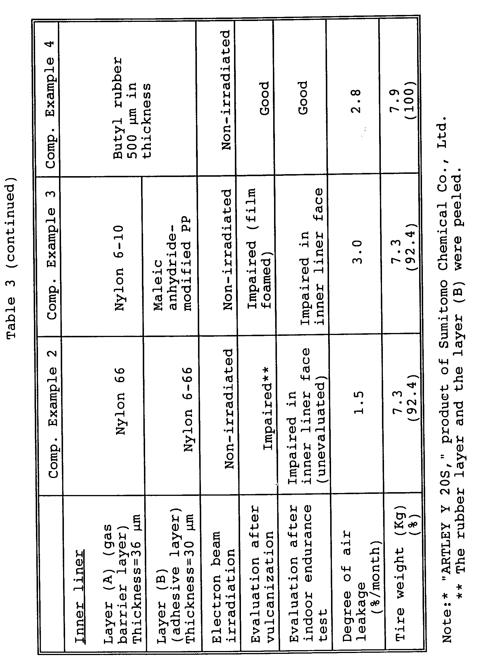
- The rubber composition used for the carcass layer had the formulation as shown below in Table 4. The carcass layer had an array of polyester cords embedded in the rubber composition.
Table 4 Component Part by weight Natural rubber 80.0 SBR 1502 20.0 Carbon black FEF 50.0 Stearic acid 2.0 Zinc flower 3.0 Sulfur 3.0 Vulcanizing accelerator (NS) 1.0 Aromatic oil 2.0 - In the Examples, the laminated films were evaluated or measured by the following methods in respect of the test items indicated in the tables.
- The inner periphery of the tire was visually inspected and evaluated after vulcanization. If no abnormality was found, the result of evaluation was expressed with "Good". If an abnormality was detected, it was represented with a word "Impaired" and specifically described.
- The indoor endurance test was carried out under the following conditions by the method described below. The inner periphery of the tire was visually inspected after the test. An flawless tire was indicated with a word "Good", while an impaired tire was expressed with a word "Impaired". The impairment of the tire was specifically set forth.
- The conditions for indoor endurance test, the test method, and the criteria for evaluation are as follows.
Rim: 14 X 5½-J
Air pressure: 140 kPa Load: 6 kN
Room temperature: 38°C
The tire was let to travel at a speed of 80 km/h on a drum of 1707 mm in diameter. After travel over a distance of 10000 km, the inner periphery of the tire was visually evaluated. The tires were rated as rejects if cracking, flaking, floating layer or the like was detected. - An air leakage test was performed as follows. The tire was fitted on a rim measuring 14 X 5½-J at room temperature (21°C) and let to stand still for 48 hours under an internal pressure of 200 kPa. Then the internal pressure was readjusted to 200 kPa. The internal internal pressure was measured every 4 days over a period of 3 months starting immediately after the readjustment.
- An air leakage coefficient α was calculated according to the formula

- A ratio (β) of reduction in the internal pressure over a period of one month (%/month) was calculated by substituting 30 (days) for t according to the equation

- The procedure of Example 5 was repeated with the exception of using an inner liner formed from the components shown in Table 3. Table 3 shows the visual evaluation of the obtained tire, visual evaluation of the tire after indoor endurance test, results of air leakage test, and measurements of the tire weight.
- A tire was produced in the same manner as in Example 5 with the exception of using an inner liner formed from the components shown in Table 3 without exposure to an electron beam. Table 3 shows the visual evaluation of the obtained tire, visual evaluation of the tire after indoor endurance test, results of air leakage test, and measurements of the tire weight.
- A tire was produced in the same manner as in Example 5 with the exception of using an inner liner formed from the components shown in Table 3 without exposure to an electron beam. Table 3 shows the visual evaluation of the obtained tire, visual evaluation of the tire after indoor endurance test, results of air leakage test, and measurements of the tire weight.
- A tire was prepared by laminating, on the inner periphery of a green tire, a 500 µm-thick inner liner of unvulcanized butyl rubber having the composition shown in Table 5 so as to form an intermediate layer of tie gum about 700 µm in thickness therebetween. The green tire was vulcanized under the same conditions as in Example 5. Table 3 shows the visual evaluation of the tire after vulcanization, visual evaluation of the tire after indoor endurance test, results of air leakage test, and measurements of the tire weight.
Table 5 Component Part by weight Butyl bromide rubber 100.0 Carbon black FEF 50.0 Stearic acid 1.0 Zinc flower 3.0 Sulfur 1.0 Vulcanizing accelerator (DM) 1.0 Aromatic oil 10.0 - As apparent from Table 3, no impairment was found in the inner liners on the tires of Examples 5 to 8 after vulcanization and after indoor endurance test. These inner liners were comparable or superior in the degree of air leakage to inner liners of butyl rubber. A 7.6% decrease of the tire weight was realized by a 1/5 reduction in the thickness of the inner liners.
- The tire of Comparative Example 2 produced without exposure to an electron beam was rated as unacceptable after indoor endurance test. Hence it was improper.
- The inner liner of Comparative Example 3 produced without exposure to an electron beam created bubbles although otherwise in accord with the requirements of the invention and was evaluated as unacceptable after vulcanization. Hence it was improper.
- The procedure of Example 5 was repeated except that the gas barrier layers (A) had the thicknesses shown in Table 6. Table 6 shows the visual evaluation of the obtained tire, visual evaluation of the tire after indoor endurance test, results of air leakage test, and measurements of the tire weight.
Table 6 Example 9 Example 10 Thickness of layer (A) 3 µm 50 µm Electron beam irradiation Irradiated Irradiated Evaluation after vulcanization Good Good Evaluation after indoor endurance test Good Good Degree of air leakage (%/month) 2.7 1.6 Tire weight (Kg) (%) 7.3 (92.4) 7.3 (9.4) - The procedure of Example 5 was repeated with the exception of forming inner liners from the components shown in Table 7. Table 7 shows the visual evaluation of the obtained tire, visual evaluation of the tire after indoor endurance test, results of air leakage test, and measurements of the tire weight.
Table 7 Inner liner Example 11 Example 12 Example 13 Layer (A) (gas barrier layer) Thickness=36 µm Polyethylene terephthalate * Polyarylate ** Polyphenylene ether-polyester (polybutylene terephthalate) alloy*** Layer (B) (adhesive layer) Thickness=30 µm Ethylene-glycidyl methacrylate-methyl acrylate terpolymer Ethylene-glycidyl methacrylate-methyl acrylate terpolymer Ethylene-glycidyl methacrylate-methyl acrylate terpolymer Electron beam irradiation Irradiated Irradiated Irradiated Evaluation after vulcanization Good Good Good Evaluation after indoor endurance test Good Good Good Degree of air leakage(%/month) 1.7 1.8 2.0 Tire weight (Kg) (%) 7.3 (92.4) 7.3 (92.4) 7.3 (92.4) Note: * product of Kanebo Ltd. "PET PEFG-13" ** product of Unitika Ltd. "U-Polymer U-8060" *** product of Mitsubishi Rayon Co., Ltd. "DIA·ALLOY TX-70A" - Tires were produced in the same manner as in Example 5 except that the laminated films were produced by exposure to an electron beam in a dose of 5 Mrad, 20 Mrad and 40 Mrad, respectively at an accelerating voltage of 150 kV, 200 kV and 250 kV, respectively in Examples 14, 15 and 16, or without exposure to an electron beam in Comparative Example 5. Table 8 below shows the visual evaluation of the obtained tire, visual evaluation of the tire after indoor endurance test, results of air leakage test, and measurements of the tire weight.
Table 8 Example 14 Example 15 Example 16 Comp.Ex. 5 Accelerating voltage/Exposure dose 150 kV 5 Mrad 200 kV 20 Mrad 250 kV 40 Mrad Non-irradiated Evaluation after vulcanization Good Good Good Impaired * Evaluation after indoor endurance test Good Good Good Unevaluated** Degree of air leakage (%/month) 2.0 2.0 1.9 7.0 Tire weight (Kg) (%) 7.3 (92.4) 7.3 (92.4) 7.3 (92.4) 7.3 (92.4) Note: *=Melted and fractured **=The inner liner surface was impaired (unevaluated). - As apparent from Table 8, the inner liners of the invention were kept from fracture due to the exposure to an electron beam. The resulting tires had inner liners excellent in the adhesion to the carcass layer. Examples 17 and 18
- Three-layer laminated films for a tire with a size of 185/65 R14 were prepared by co-extrusion so as to laminate adhesive layers (B) of ethylene-ethyl acrylate copolymer (100 parts by weight of copolymer used) containing 3 parts by weight of triallyl isocyanurate (TAIC) in the structure of FIG. 2 on both sides of a gas barrier layer (A) of nylon 66. The laminated films were irradiated at both sides with an electron beam under the conditions shown in Table 9. The thickness of the laminated films was 96 µm (

- The laminated films thus obtained were used as inner liners. Unvulcanized tires with said inner liner laminated on the
carcass layer 2 were vulcanized at 180°C for 10 minutes to heat-bond the adhesive layer (B) to thecarcass layer 2, giving a finished tire. Table 9 shows the visual evaluation of the obtained tire, visual evaluation of the tire after indoor endurance test, results of air leakage test, and measurements of the tire weight. - The rubber composition used for the carcass layer had the formulation as shown above in Table 4. The carcass layer had an array of polyester cords embedded in the rubber composition.
Table 9 Example 17 Example 18 Layer (A) (gas barrier layer) Thickness=36µm Nylon 66 Nylon 66 Layer (B) (adhesive layer) Thickness=30 µm Ethylene-ethyl acrylate-maleic anhydride terpolymer/TAIC Ethylene-ethyl acrylate-maleic anhydride terpolymer/TAIC Accelerating voltage/Exposure dose 150 kV 0.5 Mrad 150 kV 3.0 Mrad Evaluation after vulcanization Good Good Evaluation after indoor endurance test Good Good Degree of air leakage (%/month) 1.9 1.9 Tire weight (Kg) (%) 7.3 (92.4) 7.3 (92.4) - As apparent from Table 9, because of TAIC incorporated in the adhesive layer (B), the inner liners of the invention were kept from fracture although exposed to only a small dose (0.5 Mrad) of an electron beam, and were imparted a high adhesion to the carcass layer.
- Five-layer laminated films for a tire with a size of 185/65 R14 were formed by laminating, in the structure of FIG. 2, rubber-adhering layers (D) of ethylene-ethyl acrylate copolymer (EEA), adhesive layers (B) of ethylene-ethyl acrylate-maleic anhydride terpolymer (modified ethylene-acrylic acid copolymer) and a gas barrier layer (A) of nylon 66. The lamination was conducted as follows. A T-die was connected to 5 extruders independently operable. Among the five extruders, the resin for the rubber-adhering layers (D) was supplied to two extruders, the resin for the adhesive layers (B) to two extruders, and the resin for the gas barrier layer (A) to the other extruder. After co-extrusion, the molten laminated 5 layers were quenched with a roll cooled with water, giving laminated films of 5 flat layers with a structure of (D)/(B)/(A)/(B)/(D). The thickness of the laminated films was 100 µm (

- The laminated films thus obtained were used as an inner liner. An unvulcanized tire with said inner liner laminated on the
carcass layer 2 was vulcanized at 180°C for 10 minutes to heat-bond the rubber layer (D) to thecarcass layer 2, giving a finished tire. Table 10 below shows the visual evaluation of the obtained tire, visual evaluation of the tire after indoor endurance test, results of air leakage test, and measurements of the tire weight.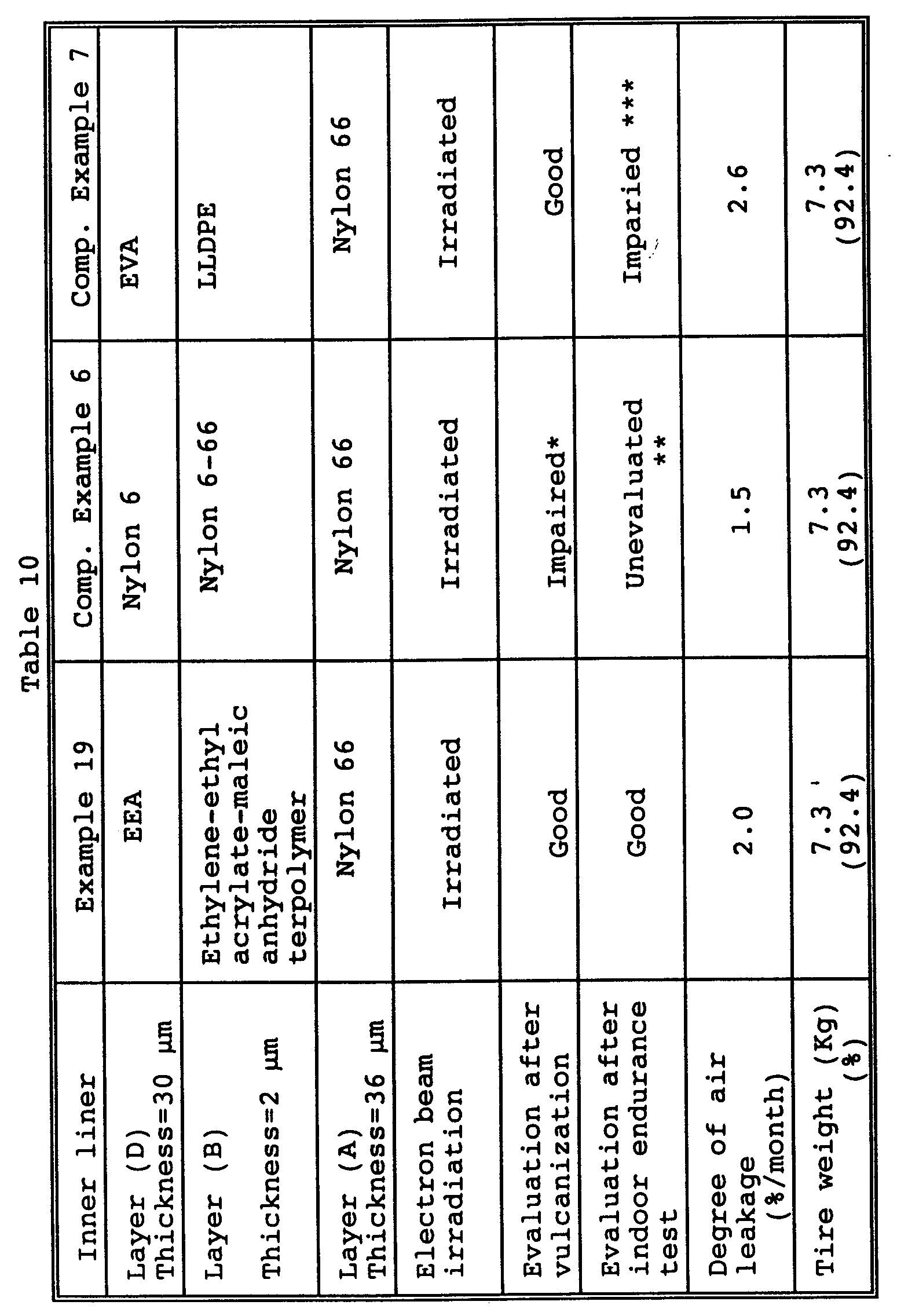


- The rubber composition used for the carcass layer had the formulation as shown above in Table 4. The carcass layer had an array of polyester cords embedded in the rubber composition.
- The procedure of Example 19 was repeated with the exception of forming inner liners from the components shown in Table 10. Table 10 shows the visual evaluation of the obtained tire, visual evaluation of the tire after indoor endurance test, results of air leakage test, and measurements of the tire weight.
- A tire was produced by repeating the procedure of Example 19 with the exception of forming an inner liner from the components shown in Table 10 without exposure to an electron beam. Table 10 shows the visual evaluation of the obtained tire, visual evaluation of the tire after indoor endurance test, results of air leakage test, and measurements of the tire weight.
- A tire was produced by laminating, on the inner periphery of a green tire, a 500 µm-thick inner liner of unvulcanized butyl rubber having the formulation shown in Table 5 so as to form an intermediate layer of tie gum about 700 µm in thickness therebetween. The green tire was vulcanized under the same conditions as in Example 19. Table 10 shows the visual evaluation of the tire after vulcanization, visual evaluation of the tire after indoor endurance test, results of air leakage test, and measurements of the tire weight.
- As apparent from Table 10, no impairment was found in the inner liner of Example 19 after vulcanization and after indoor endurance. The inner liner of Example 19 was comparable or superior in the degree of air leakage to inner liners of butyl rubber. A 7.6% decrease of the tire weight was realized by a 1/5 reduction in the thickness of the inner liner of Example 19.
- In the inner liners of Comparative Examples 6 to 8, at least one of the layers (D), (B) and (A) deviated from the scope of the invention. The inner liners were found unacceptable after indoor endurance test. Hence they were improper.
- The inner liner of Comparative Example 9, which met the structural requirements of the invention, caused bubbles because of non-exposure to an electron beam. The inner liner was evaluated as unacceptable after vulcanization. Namely it was improper.
- A tire was produced in the same manner as in Example 19 except that the gas barrier layer (A) of the laminated films was composed of polyphenylene ether/polyamide (nylon 6) alloy ("ARTLEY Y 20S," product of Sumitomo Chemical Co., Ltd.). Table 11 shows the visual evaluation of the tire after vulcanization, visual evaluation of the tire after indoor endurance test, results of air leakage test, and measurements of the tire weight.
- Tires were produced in the same manner as in Example 20 except that the gas barrier layer (A) of the laminated films was composed of polyethylene terephthalate, polyacrylate or polyphenylene ether/polyester (polybutylene terephthalate) alloy ("DIA· Alloy TX-70A," product of Mitsubishi Rayon Co., Ltd.), the rubber-adhering layer (D) was formed from an ethylene-methyl methacrylate copolymer (EMMA) and the adhesive layer (B) was made of low-density maleic anhydride-modified polyethylene. Table 11 below shows the visual evaluation of the tire after vulcanization, visual evaluation of the tire after indoor endurance test, results of air leakage test, and measurements of the tire weight.
Table 11 Inner liner Example 20 Example 21 Example 22 Example 23 Layer (D) thickness=30 µm EEA EMMA EMMA EMMA Layer (B) thickness=2 µm Ethylene-ethyl acrylate-maleic anhydride terpolymer Low-density maleic anhydride-modified polyethylene Low-density maleic anhydride-modified polyethylene Low-density maleic anhydride-modified polyethylene Layer (A) thickness=36 µm Polyphenylene ether/polyamide alloy Polyethylene terephthalate Polyacrylate Polyphenylene ether/polyester alloy Electron beam irradiation Irradiated Irradiated Irradiated Irradiated Evaluation after vulcanization Good Good Good Good Evaluation after indoor endurance test Good Good Good Good Degree of air leakage (%/month) 2.2 1.7 1.8 2.0 Tire weight (Kg) (%) 7.3 (92.4) 7.3 (92.4) 7.3 (92.4) 7.3 (92.4) - As apparent from Table 11, even when the gas barrier (A) of the laminated films in the tire was composed of polyphenylene ether/polyamide alloy, polyethylene terephthalate, polyacrylate or polyphenylene ether/polyester alloy, no impairment was found in the inner liners after vulcanization and after indoor endurance as in Example 19. The inner liners were comparable or superior in the degree of air leakage to the conventional inner liner of butyl rubber indicated in Comparative Example 6. A 7.6% decrease of the tire weight was achieved as a result of a 1/5 reduction in the thickness of the inner liner.
- Tires were produced in the same manner as in Example 19 except that the gas barrier layers (A) of the laminated films used as the inner liners had the thicknesses indicated in Table 12. Table 12 shows the visual evaluation of the tire after vulcanization, visual evaluation of the tire after indoor endurance test, results of air leakage test, and measurements of the tire weight.
- A tire was produced in the same manner as in Example 19 except that the gas barrier layer (A) of the laminated films used as the inner liner had the thickness indicated in Table 12. Table 12 shows the visual evaluation of the tire after vulcanization, visual evaluation of the tire after indoor endurance test, results of air leakage test, and measurements of the tire weight.
Table 12 Inner liner Example 24 Example 25 Comparative Example 11 Thickness of layer (A) 3 µm 50 µm 2 µm Electron beam irradiation Irradiated Irradiated Irradiated Evaluation after vulcanization Good Good Good Evaluation after indoor endurance test Good Good Good Degree of air leakage (%/month) 2.7 1.7 2.9 Tire weight (Kg) (%) 7.3 (92.4) 7.3 (92.4) 7.3 (92.4) - As apparent from Table 12, when the gas barrier layer (A) of the laminated films was at least 3 µm in thickness, there was provided a tire which was comparable or superior in the air pressure retentivity to tires with inner liners of butyl rubber.
- Tires were produced in the same manner as in Example 19 except that the gas barrier layers (A) of the laminated films were composed of the polyphenylene ether/polyamide alloy used in Example 20 and the polyphenylene ether/polyester alloy used in Example 23, respectively and had the thicknesses indicated in Table 13. Table 13 shows the visual evaluation of the tire after vulcanization, visual evaluation of the tire after indoor endurance test, results of air leakage test, and measurements of the tire weight.
Table 13 Inner liner Example 26 Example 27 Layer (A) Polyphenylene ether/polyamide alloy Polyphenylene ether/polyester alloy Thickness of layer (A) 3 µm 3 µm Electron beam irradiation Irradiated Irradiated Evaluation after vulcanization Good Good Evaluation after indoor endurance test Good Good Degree of air leakage (%/month) 2.7 2.6 Tire weight (Kg) (%) 7.3 (92.4) 7.3 (92.4) - As apparent from Table 13, even when the gas barrier layers (A) of the laminated films were composed of polyphenylene ether/polyamide alloy and polyphenylene ether/polyester alloy, respectively, the resulting tires with the layers (A) of at least 3 µm thickness were comparable or superior in the air pressure retentivity to the tire of Comparative Example 10 having the inner liner of butyl rubber, and were excellent in the heat resistance.
- Five-layer laminated films for a tire with a size of 185/65 R14 were produced. The inner liners comprised rubber-adhering layers (D) of linear low-density polyethylene (LLDPE), adhesive layers (B) of linear low-density maleic anhydride-modified polyethylene (modified LLDPE), and a gas barrier layer (A) of nylon 66 in the structure as shown in FIG. 2. The lamination was conducted as follows. A T-die was connected to 5-extruders independently operable. Among the five extruders, the resin for the rubber-adhering layers (D) was supplied to two extruders, the resin for the adhesive layers (B) to two extruders, and the resin for the gas barrier layer (A) to the other extruder. After co-extrusion, the molten laminated 5 layers were quenched with a roll cooled with water, giving laminated films composed of 5 flat layers with a structure of (D)/(B)/ (A)/(B)/(D). The thickness of the laminated films was 100 µm (

- Tires were produced in the same manner as in Examples 28 to 30 with the exception of difference in non-exposure or exposure to an electron beam in a dose of 4 or 45 Mrad at an accelerating voltage of 140 or 250 kV as shown in Table 14. Table 14 shows the visual evaluation of the tire after vulcanization, visual evaluation of the tire after indoor endurance test, results of air leakage test, and measurements of the tire weight.
Table 14 Example 28 Example 29 Example 30 Comp. Ex.12 Comp. Ex.13 Comp. Ex.14 Accelerating voltage Exposure dose 150 kV 5 Mrad 200 kV 20 Mrad 250 kV 40 Mrad Non-irradiated 140 kV 4 Mrad 250 kV 45 Mrad Evaluation after vulcanization Good Good Good Impaired (Melted & broken) Impaired (Foamed surface) Good Evaluation after indoor endurance test Good Good Good Unevaluated * Good Impaired ** Degree of air leakage (%/month) 1.9 1.9 1.9 7.0 1.9 1.9 Tire weight (Kg) 7.3 (92.4) 7.3 (92.4) 7.3 (92.4) 7.3 (92.4) 7.3 (92.4) 7.3 (92.4) Note: * The inner liner surface was impaired (unevaluated). ** The rubber layer and the layer (D) were peeled. - As apparent from Table 14, the laminated films of Examples 28 to 30 were irradiated with an electron beam in a dose of 5 to 40 Mrad at an accelerating voltage of 150 to 250 kV, and thereby made free of fracture. The obtained tires were provided with the inner liners having an increased adhesion to the carcass layer.
- Three different laminated films were produced in the same manner as in Examples 28 to 30 except that the gas barrier layer (A) of the laminated films was composed of polyphenylene ether/polyamide alloy. The laminated films were irradiated with an electron beam in a dose of 5, 20 and 40 Mrad at an accelerating voltage of 150, 200 and 250 kV, respectively. Using the laminated films, tires were produced by the same procedure as in Example 19. Table 15 shows the visual evaluation of the tire after vulcanization, visual evaluation of the tire after indoor endurance test, results of air leakage test, and measurements of the tire weight.
- Tires were produced in the same manner as in Examples 31 to 33 with the exception of difference in non-exposure or exposure to an electron beam in a dose of 100 Mrad at an accelerating voltage of 250 kV as shown in Table 15. Table 15 shows the visual evaluation of the tire after vulcanization, visual evaluation of the tire after indoor endurance test, results of air leakage test, and measurements of the tire weight.
Table 15 Example 31 Example 32 Example 33 Comp. Ex. 15 Comp. Ex. 16 Accelerating voltage/Exposure dose 150 kV 5 Mrad 200 kV 20 Mrad 250 kV 40 Mrad Non-irradiated 250 kV 100 Mrad Evaluation after vulcanization Good Good Good Impaired* Good Evaluation after indoor endurance test Good Good Good Unevaluated** Impaired *** Degree of air leakage (%/month) 2.1 2.1 2.1 7.0 1.9 Tire weight (Kg) (%) 7.3 (92.4) 7.3 (92.4) 7.3 (92.4) 7.3 (92.4) 7.3 (92.4) Note: * The inner liner was melted and fractured. ** The inner liner surface was impaired (unevaluated). *** The rubber layer and the layer (D) were peeled. - As apparent from Table 15, the inner liners formed of polyamide-based alloy according to the invention were kept from fracture due to the exposure to an electron beam in a dose of 40 Mrad or less. The inner liners were imparted an increased adhesion to the carcass layer.
- 5-layer laminated films for a tire with a size of 185/65 R14 were formed by laminating, in the structure of FIG. 2, rubber-adhering layers (D) of ethylene-ethyl acrylate copolymer (EEA) (100 parts by weight used) containing 3 parts by weight of triallyl isocyanurate (TAIC), adhesive layers (B) of ethylene-ethyl acrylate-maleic anhydride terpolymer (100 parts by weight used) containing 3 parts by weight of TAIC and a gas barrier layer (A) of nylon 66. The lamination was conducted as follows. A T-die was connected to 5 extruders independently operable. Among the five extruders, the resin for the rubber-adhering layers (D) was supplied to two extruders, the resin for the adhesive layers (B) to two extruders, and the resin for the gas barrier layer (A) to the other extruder. After co-extrusion, the molten laminated 5 layers were quenched with a roll cooled with water, giving laminated films composed of 5 flat layers with a structure of (D)/(B)/(A)/(B)/(D). The thickness of the laminated films was 100 µm (

Table 16 Inner liner Example 34 Example 35 Layer (D) (thickness=30 µm) EEA/TAIC EEA/TAIC Layer (B) (Thickness=30 µm) Ethylene-ethyl acrylate-maleic anhydride terpolymer/TAIC Ethylene-ethyl acrylate-maleic anhydride terpolymer/TAIC Layer (A) (Thickness=30 µm) Nylon 66 Nylon 66 Accelerating voltage/Exposure dose 150 kV 0.5 Mrad 150 kV 3.0 Mrad Evaluation after vulcanization Good Good Evaluation after indoor endurance test Good Good Degree of air leakage (%/month) 1.9 1.9 Tire weight (Kg) (%) 7.3 (92.4) 7.3 (92.4) - As apparent from Table 16, because of TAIC incorporated in the rubber-adhering layers (D) and the adhesive layers (B), the inner liners of the invention were kept from fracture although exposed to only a small dose (0.5 Mrad) of an electron beam, and were imparted a high adhesion to the carcass layer.


Claims (16)
- A laminate comprising laminated films and a rubber layer (R), the laminated films being comprised of a gas barrier layer (A) and an adhesive layer (B), the layer (B) being provided on at least one side of the layer (A), the layer (A) being formed of at least one member selected from the group consisting of polyamide resins, polyester resins, polyarylate resins, polyamide-based alloys and polyester-based alloys, the laminated films being irradiated in at least one periphery with an electron beam, and the adhesive layer (B) being heat-bonded to the rubber layer (R).
- The laminate according to claim 1 wherein the adhesive layer (B) is formed of at least one adhesive resin.
- The laminate according to one or more of the claims 1 to 2 wherein the adhesive resin is a modified polymer.
- The laminate according to one or more of the claims 1 to 3 wherein the rubber layer (R) is formed of at least one member selected from the group consisting of diene-based rubbers, hydrogenated diene-based rubbers, olefin-based rubbers, halogen-containing rubbers and thermoplastic elastomers.
- The laminate according to one or more of the claims 1 to 4 wherein the gas barrier layer (A) has a thickness of at least 3 µm.
- The laminate according to one or more of the claims 1 to 5 wherein the laminated films were irradiated with an electron beam at an accelerating voltage of at least 150 kV.
- The laminate according to one or more of the claims 1 to 6 wherein the laminated films were irradiated with an electron beam in a dose of 5 to 40 Mrad.
- A pneumatic tie wherein the laminated films in the laminate of one or more of the claims 1 to 7 are used as an air-impermeable layer.
- A laminate comprising laminated films and a rubber layer (R), the laminated films being comprised of a rubber-adhering layer (D), an adhesive layer (B) and a gas barrier layer (A), the layers (D), (B) and (A) being laminated in this order with a structure of at least three layers, the rubber-adhering layer (D) being formed of at least one polyolefin resin, the gas barrier-layer (A) being formed of at least one member selected from the group consisting of polyamide resins, polyester resins, polyarylate resins, polyamide-based alloys and polyester-based alloys, the laminated films being irradiated in at least one periphery with an electron beam, and the rubber-adhering layer (D) being heat-bonded to the rubber layer (R).
- The laminate according to claim 9 wherein the adhesive layer (B) is formed of at least one adhesive resin.
- The laminate according to one or more of the claims 9 to 10 wherein the adhesive resin is a modified polymer.
- The laminate according to one or more of the claims 9 to 11 wherein the rubber layer (R) is formed of at least one member selected from the group consisting of diene-based rubbers, hydrogenated diene-based rubbers, olefin-based rubbers, halogen-containing rubbers and thermoplastic elastomers.
- The laminate according to one or more of the claims 9 to 12 wherein the gas barrier layer (A) has a thickness of at least 3 µm.
- The laminate according to one or more of the claims 9 to 13 wherein the laminated films were irradiated with an electron beam at an accelerating voltage of at least 150 kV.
- The laminate according to one or more of the claims 9 to 14 wherein the laminated films were irradiated with an electron beam in a dose of 5 to 40 Mrad.
- A pneumatic tire wherein the laminated films in the laminate of one or more of the claims 9 to 15 are used as an air-impermeable layer.
Applications Claiming Priority (9)
| Application Number | Priority Date | Filing Date | Title |
|---|---|---|---|
| JP218732/94 | 1994-09-13 | ||
| JP21873294 | 1994-09-13 | ||
| JP21873294 | 1994-09-13 | ||
| JP7171799A JPH0919987A (en) | 1995-07-07 | 1995-07-07 | Laminate |
| JP171799/95 | 1995-07-07 | ||
| JP172023/95 | 1995-07-07 | ||
| JP17202395 | 1995-07-07 | ||
| JP17179995 | 1995-07-07 | ||
| JP7172023A JPH08132553A (en) | 1994-09-13 | 1995-07-07 | Laminate |
Publications (3)
| Publication Number | Publication Date |
|---|---|
| EP0706878A2 true EP0706878A2 (en) | 1996-04-17 |
| EP0706878A3 EP0706878A3 (en) | 1996-07-24 |
| EP0706878B1 EP0706878B1 (en) | 2000-08-23 |
Family
ID=27323530
Family Applications (1)
| Application Number | Title | Priority Date | Filing Date |
|---|---|---|---|
| EP95114316A Expired - Lifetime EP0706878B1 (en) | 1994-09-13 | 1995-09-12 | Laminate |
Country Status (3)
| Country | Link |
|---|---|
| US (1) | US5992486A (en) |
| EP (1) | EP0706878B1 (en) |
| DE (1) | DE69518481T2 (en) |
Cited By (21)
| Publication number | Priority date | Publication date | Assignee | Title |
|---|---|---|---|---|
| WO2000037268A1 (en) * | 1998-12-21 | 2000-06-29 | Honda Giken Kogyo Kabushiki Kaisha | Tubeless tire |
| EP1437371A1 (en) * | 2003-01-07 | 2004-07-14 | Mitsubishi Gas Chemical Company, Inc. | Pneumatic tire comprising polyurethane skin layer with gas barrier properties |
| EP1724126A3 (en) * | 2001-09-14 | 2006-11-29 | The Yokohama Rubber Co., Ltd. | Pneumatic tire, process for producing the same |
| WO2007081323A1 (en) * | 2006-01-10 | 2007-07-19 | The Yokohama Rubber Co., Ltd. | Laminate of thermoplastic polymer composition having low air permeability and pneumatic tire using same as inner liner |
| WO2008051253A1 (en) * | 2006-10-26 | 2008-05-02 | Exxonmobil Chemical Patents Inc. | Low moisture permeability laminate construction |
| EP2123479A1 (en) * | 2008-05-21 | 2009-11-25 | The Goodyear Tire & Rubber Company | Tire with air barrier layer |
| EP2058142A4 (en) * | 2006-10-30 | 2010-07-07 | Yokohama Rubber Co Ltd | Pneumatic tire and process for producing the same |
| FR2944227A1 (en) * | 2009-04-09 | 2010-10-15 | Michelin Soc Tech | MULTILAYER LAMINATE FOR PNEUMATIC BANDAGE |
| RU2429973C2 (en) * | 2006-10-26 | 2011-09-27 | Эксонмобил Кемикал Пэйтентс Инк. | Laminar structure with low moisture permeability |
| EP1930152A4 (en) * | 2005-09-30 | 2011-11-16 | Yokohama Rubber Co Ltd | Poorly air-permeable rubber laminate composed of poorly air-permeable resin and rubber composition, and method for production thereof |
| EP1974907A4 (en) * | 2006-01-17 | 2012-04-04 | Yokohama Rubber Co Ltd | Low-permeable rubber laminate and pneumatic tire using same |
| CN102555677A (en) * | 2010-11-15 | 2012-07-11 | 固特异轮胎和橡胶公司 | Pneumatic tire with an innerliner and method of making the same |
| EP2497631A1 (en) * | 2011-03-08 | 2012-09-12 | Sumitomo Rubber Industries, Ltd. | Production method of heavy duty pneumatic tire |
| CN101511573B (en) * | 2006-09-04 | 2013-05-01 | 横滨橡胶株式会社 | Method of forming inner liner for tire and process for producing pneumatic tire |
| EP2839972A1 (en) * | 2013-08-22 | 2015-02-25 | The Goodyear Tire & Rubber Company | Tire having laminated innerliner with reinforced splice |
| EP2871068A4 (en) * | 2012-07-03 | 2016-02-24 | Yokohama Rubber Co Ltd | LAMINATE FOR TIRES |
| EP3081394A1 (en) | 2015-04-16 | 2016-10-19 | The Goodyear Tire & Rubber Company | Tire with spliced multilayered film innerliner |
| US9539859B2 (en) | 2010-06-08 | 2017-01-10 | The Yokohama Rubber Co., Ltd. | Pneumatic tire and laminate |
| EP3196011A1 (en) | 2016-01-11 | 2017-07-26 | The Goodyear Tire & Rubber Company | Tire with non-spliced multilayered film innerliner |
| US9889703B2 (en) | 2014-12-16 | 2018-02-13 | The Goodyear Tire & Rubber Company | Tire with spliced film innerliner |
| CN110536805A (en) * | 2017-04-19 | 2019-12-03 | 横滨橡胶株式会社 | Pneumatic tire and its manufacturing method |
Families Citing this family (47)
| Publication number | Priority date | Publication date | Assignee | Title |
|---|---|---|---|---|
| US6497947B1 (en) * | 1999-08-16 | 2002-12-24 | Ford Global Technologies, Inc. | Interior automotive trim member having improved scratch resistance and a method of making the same |
| US6544608B1 (en) * | 1999-10-08 | 2003-04-08 | Satish Jain | Bladder shell for inflatable balls |
| US7550217B2 (en) * | 2003-06-09 | 2009-06-23 | Saint-Gobain Ceramics & Plastics, Inc. | Stack supported solid oxide fuel cell |
| KR101136191B1 (en) * | 2003-09-10 | 2012-04-17 | 트르스티스 오브 보스톤 유니버시티 | Process for solid oxide fuel cell manufacture |
| JP4613508B2 (en) * | 2004-04-06 | 2011-01-19 | 横浜ゴム株式会社 | Pneumatic tire containing oxygen absorber |
| DE102004020076A1 (en) * | 2004-04-24 | 2005-11-17 | Bayerische Motoren Werke Ag | Tubeless vehicle tire has an inner airtight layer of composite thermoplastic film forming part of the tire inner walls |
| US20060032568A1 (en) * | 2004-08-11 | 2006-02-16 | Annette Lechtenboehmer | Tire with oxygen scavenging barrier |
| US8696846B2 (en) * | 2005-01-11 | 2014-04-15 | Yokohama Rubber Co., Ltd. | Method of manufacturing a pneumatic tire |
| JP5498021B2 (en) * | 2006-01-09 | 2014-05-21 | サン−ゴバン セラミックス アンド プラスティクス,インコーポレイティド | Fuel cell assembly having porous electrodes |
| JPWO2007116983A1 (en) * | 2006-04-04 | 2009-08-20 | 横浜ゴム株式会社 | Pneumatic tire having a light shielding layer on the surface |
| EP2013936A2 (en) * | 2006-04-05 | 2009-01-14 | Saint-Gobain Ceramics and Plastics, Inc. | A sofc stack having a high temperature bonded ceramic interconnect and method for making same |
| CN101460318B (en) * | 2006-06-02 | 2011-11-23 | 株式会社普利司通 | Pneumatic tire |
| US8302648B2 (en) * | 2006-09-04 | 2012-11-06 | The Yokohama Rubber Co., Ltd. | Pneumatic tire |
| US20100126647A1 (en) * | 2006-09-05 | 2010-05-27 | The Yokohama Rubber Co., Ltd. | Pneumatic tire |
| JP4368413B2 (en) * | 2006-11-02 | 2009-11-18 | 横浜ゴム株式会社 | Method for producing low-permeability rubber laminate using multilayer film of low-permeability resin |
| WO2008149909A1 (en) * | 2007-05-30 | 2008-12-11 | The Yokohama Rubber Co., Ltd. | Low-permeability laminate, and pneumatic tire utilizing the same |
| US20100193098A1 (en) * | 2007-07-23 | 2010-08-05 | The Yokohama Rubber Co., Ltd. | Pneumatic tire |
| KR101051563B1 (en) * | 2007-11-06 | 2011-07-22 | 가부시키가이샤 브리지스톤 | Inner liner for tires and tires using same |
| US8652624B2 (en) | 2007-11-14 | 2014-02-18 | Dow Global Technologies Llc | Articles and methods of making the same |
| US20090151846A1 (en) * | 2007-12-15 | 2009-06-18 | Junling Zhao | Tire with innerliner containing low melting polyamide |
| JP4346666B2 (en) * | 2008-02-26 | 2009-10-21 | 横浜ゴム株式会社 | Pneumatic tire |
| US8281827B2 (en) * | 2008-11-06 | 2012-10-09 | The Yokohama Rubber Co., Ltd. | Pneumatic tire |
| DE102009003517A1 (en) | 2008-12-22 | 2010-07-01 | Continental Reifen Deutschland Gmbh | Vehicle tires |
| CN102458385A (en) * | 2009-05-08 | 2012-05-16 | 3M创新有限公司 | Oral care method and kit |
| KR101338506B1 (en) | 2010-03-31 | 2013-12-10 | 코오롱인더스트리 주식회사 | Film for tire inner-liner and preparation method thereof |
| WO2012002750A2 (en) * | 2010-06-30 | 2012-01-05 | 코오롱인더스트리 주식회사 | Film for tire inner liner, and preparation method thereof |
| WO2012042679A1 (en) * | 2010-10-01 | 2012-04-05 | 株式会社クラレ | Multilayered structure, and inner liner and pneumatic tire using same |
| FR2967611B1 (en) * | 2010-10-14 | 2015-04-17 | Michelin Soc Tech | PNEUMATIC HAVING FLANKS REINFORCED BY A THERMOPLASTIC POLYMER FILM |
| JP5247852B2 (en) | 2010-11-05 | 2013-07-24 | 住友ゴム工業株式会社 | Pneumatic tire manufacturing method |
| JP5225431B2 (en) | 2010-12-06 | 2013-07-03 | 住友ゴム工業株式会社 | Strip, method for producing the same, and method for producing a pneumatic tire |
| KR20140001835A (en) * | 2010-12-13 | 2014-01-07 | 도레이 카부시키가이샤 | Multilayer sheet and method for producing same |
| CN202015459U (en) * | 2011-03-25 | 2011-10-26 | 福建元吉体育用品有限公司(外资企业) | A new type of two-layer anti-leakage ball |
| WO2012165512A1 (en) * | 2011-05-31 | 2012-12-06 | 株式会社ブリヂストン | Laminate, tire, and method for producing tire |
| KR20140044902A (en) | 2011-07-28 | 2014-04-15 | 스미토모 고무 고교 가부시키가이샤 | Pneumatic tire |
| US9902199B2 (en) | 2011-11-09 | 2018-02-27 | Sumitomo Rubber Industries, Ltd. | Pneumatic tire |
| CN103998550B (en) * | 2011-11-15 | 2016-10-19 | 普利司通美国轮胎运营有限责任公司 | Multiple cord tie liner product of winding and preparation method thereof |
| JP5146591B1 (en) * | 2011-12-22 | 2013-02-20 | 横浜ゴム株式会社 | Pneumatic tire manufacturing method |
| IN2014DN07459A (en) * | 2012-02-29 | 2015-04-24 | Bridgestone Corp | |
| CN104144797B (en) * | 2012-02-29 | 2016-06-22 | 株式会社普利司通 | tire |
| WO2013168676A1 (en) * | 2012-05-08 | 2013-11-14 | 株式会社ブリヂストン | Rubber sheet, pneumatic tire using same, and method for producing rubber sheet |
| JP5928227B2 (en) * | 2012-07-31 | 2016-06-01 | 横浜ゴム株式会社 | Pneumatic tire manufacturing method |
| JP5443554B2 (en) | 2012-08-01 | 2014-03-19 | 住友ゴム工業株式会社 | Pneumatic tire with inner liner |
| JP6163721B2 (en) * | 2012-09-12 | 2017-07-19 | 住友ベークライト株式会社 | Tire inner liner seat and tire |
| CA2902328A1 (en) | 2013-03-13 | 2014-10-09 | Basf Se | Inner liner for a pneumatic tire assembly |
| JP6236855B2 (en) * | 2013-04-26 | 2017-11-29 | 横浜ゴム株式会社 | Tire manufacturing method |
| JP6065085B2 (en) * | 2015-11-02 | 2017-01-25 | 横浜ゴム株式会社 | Pneumatic tire manufacturing method |
| EP3722086A1 (en) * | 2019-04-12 | 2020-10-14 | Nitto Denko Corporation | Multilayer films for airbag applications |
Citations (1)
| Publication number | Priority date | Publication date | Assignee | Title |
|---|---|---|---|---|
| JPH0640207A (en) | 1992-07-24 | 1994-02-15 | Yokohama Rubber Co Ltd:The | Pneumatic tire and manufacture thereof |
Family Cites Families (13)
| Publication number | Priority date | Publication date | Assignee | Title |
|---|---|---|---|---|
| US3650669A (en) * | 1969-01-28 | 1972-03-21 | Union Carbide Corp | Treatment of monomeric and polymeric systems with high intensity predominantly continuum light radiation |
| GB1420955A (en) * | 1972-06-15 | 1976-01-14 | Dunlop Ltd | Bonding polyamide plastics to rubber compositions |
| GB1458213A (en) * | 1973-03-10 | 1976-12-08 | Dunlop Ltd | Method of adhesion |
| JPS53106779A (en) * | 1977-03-01 | 1978-09-18 | Gunze Kk | Production of easily tearable biaxzally stretched polypropylene film |
| CA1215619A (en) * | 1982-09-07 | 1986-12-23 | John Walker | Pneumatic tire and inner liner therefor having puncture sealing characteristics |
| US5040583A (en) * | 1988-04-11 | 1991-08-20 | Hercules Incorporated | Tire innerliner |
| US5156921A (en) * | 1988-04-11 | 1992-10-20 | Hercules Incorporated | Tire innerliner |
| JPH0639104B2 (en) * | 1989-12-22 | 1994-05-25 | 住友ゴム工業株式会社 | Elastomer article and method for producing the same |
| JPH045104A (en) * | 1990-04-23 | 1992-01-09 | Yokohama Rubber Co Ltd:The | Pneumatic tire and its manufacture |
| CA2063868C (en) * | 1991-03-25 | 2002-11-12 | Walter Berndt Mueller | Nylon copolymer medical film |
| JPH0655682A (en) * | 1992-08-06 | 1994-03-01 | Gunze Ltd | Heat-shrinkable multilayer film |
| JPH06126894A (en) * | 1992-10-19 | 1994-05-10 | Yokohama Rubber Co Ltd:The | Polyethylene/rubber composite adhesive |
| US5686505A (en) * | 1994-12-07 | 1997-11-11 | Bridgestone Corporation | Process and apparatus for surface treatment of unvulcanized rubber sheet |
-
1995
- 1995-09-12 US US08/527,214 patent/US5992486A/en not_active Expired - Fee Related
- 1995-09-12 DE DE69518481T patent/DE69518481T2/en not_active Expired - Fee Related
- 1995-09-12 EP EP95114316A patent/EP0706878B1/en not_active Expired - Lifetime
Patent Citations (1)
| Publication number | Priority date | Publication date | Assignee | Title |
|---|---|---|---|---|
| JPH0640207A (en) | 1992-07-24 | 1994-02-15 | Yokohama Rubber Co Ltd:The | Pneumatic tire and manufacture thereof |
Cited By (35)
| Publication number | Priority date | Publication date | Assignee | Title |
|---|---|---|---|---|
| WO2000037268A1 (en) * | 1998-12-21 | 2000-06-29 | Honda Giken Kogyo Kabushiki Kaisha | Tubeless tire |
| EP1724126A3 (en) * | 2001-09-14 | 2006-11-29 | The Yokohama Rubber Co., Ltd. | Pneumatic tire, process for producing the same |
| EP1437371A1 (en) * | 2003-01-07 | 2004-07-14 | Mitsubishi Gas Chemical Company, Inc. | Pneumatic tire comprising polyurethane skin layer with gas barrier properties |
| US7240708B2 (en) | 2003-01-07 | 2007-07-10 | Mitsubishi Gas Chemical Company, Inc. | Pneumatic tire |
| EP1930152A4 (en) * | 2005-09-30 | 2011-11-16 | Yokohama Rubber Co Ltd | Poorly air-permeable rubber laminate composed of poorly air-permeable resin and rubber composition, and method for production thereof |
| WO2007081323A1 (en) * | 2006-01-10 | 2007-07-19 | The Yokohama Rubber Co., Ltd. | Laminate of thermoplastic polymer composition having low air permeability and pneumatic tire using same as inner liner |
| CN101356065B (en) * | 2006-01-10 | 2011-12-14 | 横滨橡胶株式会社 | Laminating material with low air permeability for thermoplastic polymer composition and pneumatic tire using the laminating material as inner lining |
| US8691373B2 (en) | 2006-01-10 | 2014-04-08 | The Yokohama Rubber Co., Ltd. | Laminate or thermoplastic polymer composition having low air permeability and pneumatic tire using same as inner liner |
| EP1974907A4 (en) * | 2006-01-17 | 2012-04-04 | Yokohama Rubber Co Ltd | Low-permeable rubber laminate and pneumatic tire using same |
| CN101511573B (en) * | 2006-09-04 | 2013-05-01 | 横滨橡胶株式会社 | Method of forming inner liner for tire and process for producing pneumatic tire |
| US10427457B2 (en) | 2006-10-26 | 2019-10-01 | Exxonmobil Chemical Patents Inc. | Low moisture permeability laminate construction |
| RU2429973C2 (en) * | 2006-10-26 | 2011-09-27 | Эксонмобил Кемикал Пэйтентс Инк. | Laminar structure with low moisture permeability |
| WO2008051253A1 (en) * | 2006-10-26 | 2008-05-02 | Exxonmobil Chemical Patents Inc. | Low moisture permeability laminate construction |
| US8960250B2 (en) | 2006-10-26 | 2015-02-24 | The Yokohama Rubber Co., Ltd. | Low moisture permeability laminate construction |
| EP2058142A4 (en) * | 2006-10-30 | 2010-07-07 | Yokohama Rubber Co Ltd | Pneumatic tire and process for producing the same |
| EP2123479A1 (en) * | 2008-05-21 | 2009-11-25 | The Goodyear Tire & Rubber Company | Tire with air barrier layer |
| US9186871B2 (en) | 2009-04-09 | 2015-11-17 | Michelin Recherche Et Technique S.A. | Pneumatic tire, the belt of which is reinforced by a thermoplastic polymer film |
| CN102387916B (en) * | 2009-04-09 | 2015-04-01 | 米其林企业总公司 | Pneumatic tyre, the belt of which is reinforced by a thermoplastic polymer film |
| CN102387916A (en) * | 2009-04-09 | 2012-03-21 | 米其林技术公司 | Pneumatic tyre, the belt of which is reinforced by a thermoplastic polymer film |
| FR2944227A1 (en) * | 2009-04-09 | 2010-10-15 | Michelin Soc Tech | MULTILAYER LAMINATE FOR PNEUMATIC BANDAGE |
| US9539859B2 (en) | 2010-06-08 | 2017-01-10 | The Yokohama Rubber Co., Ltd. | Pneumatic tire and laminate |
| US8454778B2 (en) | 2010-11-15 | 2013-06-04 | Ramendra Nath Majumdar | Pneumatic tire with barrier layer and method of making the same |
| CN102555677A (en) * | 2010-11-15 | 2012-07-11 | 固特异轮胎和橡胶公司 | Pneumatic tire with an innerliner and method of making the same |
| EP2452832A3 (en) * | 2010-11-15 | 2012-10-03 | The Goodyear Tire & Rubber Company | Pneumatic tire with an innerliner and method of making the same |
| CN102555677B (en) * | 2010-11-15 | 2015-06-03 | 固特异轮胎和橡胶公司 | Pneumatic tire with an innerliner and method of making the same |
| EP2497631A1 (en) * | 2011-03-08 | 2012-09-12 | Sumitomo Rubber Industries, Ltd. | Production method of heavy duty pneumatic tire |
| CN106394123B (en) * | 2012-07-03 | 2018-06-08 | 横滨橡胶株式会社 | Tire laminated body |
| EP2871068A4 (en) * | 2012-07-03 | 2016-02-24 | Yokohama Rubber Co Ltd | LAMINATE FOR TIRES |
| CN106394123A (en) * | 2012-07-03 | 2017-02-15 | 横滨橡胶株式会社 | Laminate for tires |
| EP2839972A1 (en) * | 2013-08-22 | 2015-02-25 | The Goodyear Tire & Rubber Company | Tire having laminated innerliner with reinforced splice |
| US9889703B2 (en) | 2014-12-16 | 2018-02-13 | The Goodyear Tire & Rubber Company | Tire with spliced film innerliner |
| EP3081394A1 (en) | 2015-04-16 | 2016-10-19 | The Goodyear Tire & Rubber Company | Tire with spliced multilayered film innerliner |
| EP3196011A1 (en) | 2016-01-11 | 2017-07-26 | The Goodyear Tire & Rubber Company | Tire with non-spliced multilayered film innerliner |
| US10160263B2 (en) | 2016-01-11 | 2018-12-25 | The Goodyear Tire & Rubber Company | Tire with non-spliced multilayered film innerliner |
| CN110536805A (en) * | 2017-04-19 | 2019-12-03 | 横滨橡胶株式会社 | Pneumatic tire and its manufacturing method |
Also Published As
| Publication number | Publication date |
|---|---|
| EP0706878B1 (en) | 2000-08-23 |
| US5992486A (en) | 1999-11-30 |
| EP0706878A3 (en) | 1996-07-24 |
| DE69518481D1 (en) | 2000-09-28 |
| DE69518481T2 (en) | 2001-04-19 |
Similar Documents
| Publication | Publication Date | Title |
|---|---|---|
| EP0706878B1 (en) | Laminate | |
| JPH0919987A (en) | Laminate | |
| JPH08132553A (en) | Laminate | |
| EP0857761B1 (en) | Process for making a pneumatic tire having an almost impermeable thermoplastic elastomer composition in gas-barrier layer | |
| EP0732224B1 (en) | Pneumatic tire and process of production thereof | |
| US6079465A (en) | Polymer composition for tire and pneumatic tire using same | |
| JP4942253B2 (en) | Thermoplastic elastomer composition with improved processability and tire using the same | |
| US6617383B2 (en) | Thermoplastic elastomer composition having improved processability and tire using the same | |
| CA1331734C (en) | Gas barrier structure for pneumatic articles | |
| EP1818187B1 (en) | Laminate, method for producing the same and tire using the same | |
| EP2517900B1 (en) | Laminated body and method of producing the same as well as innerliner for pneumatic tire and pneumatic tire | |
| EP2594399B1 (en) | Laminated body and pneumatic tyre using same | |
| JP3153093B2 (en) | Pneumatic tire | |
| EP0723882A1 (en) | Pneumatic tire | |
| JP3212470B2 (en) | Polymer composition for tires | |
| EP2402175B1 (en) | Method for producing pneumatic tire and pneumatic tire | |
| CN100569544C (en) | Heavy-load tire | |
| WO2014017486A1 (en) | Laminate for inner liner, and tyre using same | |
| JP2009190448A (en) | Tire | |
| EP2423000B1 (en) | Pneumatic tire and method of manufacturing same | |
| JP2002012002A (en) | Pneumatic tire and manufacturing method for it | |
| JP2009274680A (en) | Heavy duty tire | |
| JP2009040117A (en) | Tire | |
| JP2009255601A (en) | Inner liner for pneumatic tire, its manufacturing method, and pneumatic tire | |
| CN101678714A (en) | Radial tire for heavy load |
Legal Events
| Date | Code | Title | Description |
|---|---|---|---|
| PUAI | Public reference made under article 153(3) epc to a published international application that has entered the european phase |
Free format text: ORIGINAL CODE: 0009012 |
|
| AK | Designated contracting states |
Kind code of ref document: A2 Designated state(s): DE FR |
|
| PUAL | Search report despatched |
Free format text: ORIGINAL CODE: 0009013 |
|
| AK | Designated contracting states |
Kind code of ref document: A3 Designated state(s): DE FR |
|
| 17P | Request for examination filed |
Effective date: 19970123 |
|
| 17Q | First examination report despatched |
Effective date: 19990331 |
|
| GRAG | Despatch of communication of intention to grant |
Free format text: ORIGINAL CODE: EPIDOS AGRA |
|
| 17Q | First examination report despatched |
Effective date: 19990331 |
|
| GRAG | Despatch of communication of intention to grant |
Free format text: ORIGINAL CODE: EPIDOS AGRA |
|
| GRAH | Despatch of communication of intention to grant a patent |
Free format text: ORIGINAL CODE: EPIDOS IGRA |
|
| GRAH | Despatch of communication of intention to grant a patent |
Free format text: ORIGINAL CODE: EPIDOS IGRA |
|
| GRAA | (expected) grant |
Free format text: ORIGINAL CODE: 0009210 |
|
| AK | Designated contracting states |
Kind code of ref document: B1 Designated state(s): DE FR |
|
| PGFP | Annual fee paid to national office [announced via postgrant information from national office to epo] |
Ref country code: FR Payment date: 20000928 Year of fee payment: 6 |
|
| REF | Corresponds to: |
Ref document number: 69518481 Country of ref document: DE Date of ref document: 20000928 |
|
| ET | Fr: translation filed | ||
| PGFP | Annual fee paid to national office [announced via postgrant information from national office to epo] |
Ref country code: DE Payment date: 20001117 Year of fee payment: 6 |
|
| PLBE | No opposition filed within time limit |
Free format text: ORIGINAL CODE: 0009261 |
|
| STAA | Information on the status of an ep patent application or granted ep patent |
Free format text: STATUS: NO OPPOSITION FILED WITHIN TIME LIMIT |
|
| 26N | No opposition filed | ||
| PG25 | Lapsed in a contracting state [announced via postgrant information from national office to epo] |
Ref country code: DE Free format text: LAPSE BECAUSE OF NON-PAYMENT OF DUE FEES Effective date: 20020501 |
|
| PG25 | Lapsed in a contracting state [announced via postgrant information from national office to epo] |
Ref country code: FR Free format text: LAPSE BECAUSE OF NON-PAYMENT OF DUE FEES Effective date: 20020531 |
|
| REG | Reference to a national code |
Ref country code: FR Ref legal event code: ST |