JP5498021B2 - Fuel cell assembly having porous electrodes - Google Patents
Fuel cell assembly having porous electrodes Download PDFInfo
- Publication number
- JP5498021B2 JP5498021B2 JP2008549686A JP2008549686A JP5498021B2 JP 5498021 B2 JP5498021 B2 JP 5498021B2 JP 2008549686 A JP2008549686 A JP 2008549686A JP 2008549686 A JP2008549686 A JP 2008549686A JP 5498021 B2 JP5498021 B2 JP 5498021B2
- Authority
- JP
- Japan
- Prior art keywords
- layer portion
- electrode
- bulk
- functional layer
- cathode
- Prior art date
- Legal status (The legal status is an assumption and is not a legal conclusion. Google has not performed a legal analysis and makes no representation as to the accuracy of the status listed.)
- Expired - Fee Related
Links
Images


Classifications
-
- H—ELECTRICITY
- H01—ELECTRIC ELEMENTS
- H01M—PROCESSES OR MEANS, e.g. BATTERIES, FOR THE DIRECT CONVERSION OF CHEMICAL ENERGY INTO ELECTRICAL ENERGY
- H01M8/00—Fuel cells; Manufacture thereof
- H01M8/02—Details
-
- H—ELECTRICITY
- H01—ELECTRIC ELEMENTS
- H01M—PROCESSES OR MEANS, e.g. BATTERIES, FOR THE DIRECT CONVERSION OF CHEMICAL ENERGY INTO ELECTRICAL ENERGY
- H01M4/00—Electrodes
- H01M4/86—Inert electrodes with catalytic activity, e.g. for fuel cells
- H01M4/8605—Porous electrodes
- H01M4/861—Porous electrodes with a gradient in the porosity
-
- C—CHEMISTRY; METALLURGY
- C04—CEMENTS; CONCRETE; ARTIFICIAL STONE; CERAMICS; REFRACTORIES
- C04B—LIME, MAGNESIA; SLAG; CEMENTS; COMPOSITIONS THEREOF, e.g. MORTARS, CONCRETE OR LIKE BUILDING MATERIALS; ARTIFICIAL STONE; CERAMICS; REFRACTORIES; TREATMENT OF NATURAL STONE
- C04B35/00—Shaped ceramic products characterised by their composition; Ceramics compositions; Processing powders of inorganic compounds preparatory to the manufacturing of ceramic products
- C04B35/01—Shaped ceramic products characterised by their composition; Ceramics compositions; Processing powders of inorganic compounds preparatory to the manufacturing of ceramic products based on oxide ceramics
- C04B35/48—Shaped ceramic products characterised by their composition; Ceramics compositions; Processing powders of inorganic compounds preparatory to the manufacturing of ceramic products based on oxide ceramics based on zirconium or hafnium oxides, zirconates, zircon or hafnates
- C04B35/486—Fine ceramics
-
- C—CHEMISTRY; METALLURGY
- C04—CEMENTS; CONCRETE; ARTIFICIAL STONE; CERAMICS; REFRACTORIES
- C04B—LIME, MAGNESIA; SLAG; CEMENTS; COMPOSITIONS THEREOF, e.g. MORTARS, CONCRETE OR LIKE BUILDING MATERIALS; ARTIFICIAL STONE; CERAMICS; REFRACTORIES; TREATMENT OF NATURAL STONE
- C04B35/00—Shaped ceramic products characterised by their composition; Ceramics compositions; Processing powders of inorganic compounds preparatory to the manufacturing of ceramic products
- C04B35/622—Forming processes; Processing powders of inorganic compounds preparatory to the manufacturing of ceramic products
- C04B35/64—Burning or sintering processes
- C04B35/645—Pressure sintering
- C04B35/6455—Hot isostatic pressing
-
- H—ELECTRICITY
- H01—ELECTRIC ELEMENTS
- H01M—PROCESSES OR MEANS, e.g. BATTERIES, FOR THE DIRECT CONVERSION OF CHEMICAL ENERGY INTO ELECTRICAL ENERGY
- H01M4/00—Electrodes
- H01M4/86—Inert electrodes with catalytic activity, e.g. for fuel cells
- H01M4/8605—Porous electrodes
- H01M4/8621—Porous electrodes containing only metallic or ceramic material, e.g. made by sintering or sputtering
-
- H—ELECTRICITY
- H01—ELECTRIC ELEMENTS
- H01M—PROCESSES OR MEANS, e.g. BATTERIES, FOR THE DIRECT CONVERSION OF CHEMICAL ENERGY INTO ELECTRICAL ENERGY
- H01M4/00—Electrodes
- H01M4/86—Inert electrodes with catalytic activity, e.g. for fuel cells
- H01M4/88—Processes of manufacture
- H01M4/8878—Treatment steps after deposition of the catalytic active composition or after shaping of the electrode being free-standing body
- H01M4/8882—Heat treatment, e.g. drying, baking
- H01M4/8885—Sintering or firing
-
- H—ELECTRICITY
- H01—ELECTRIC ELEMENTS
- H01M—PROCESSES OR MEANS, e.g. BATTERIES, FOR THE DIRECT CONVERSION OF CHEMICAL ENERGY INTO ELECTRICAL ENERGY
- H01M4/00—Electrodes
- H01M4/86—Inert electrodes with catalytic activity, e.g. for fuel cells
- H01M4/90—Selection of catalytic material
- H01M4/9041—Metals or alloys
- H01M4/905—Metals or alloys specially used in fuel cell operating at high temperature, e.g. SOFC
- H01M4/9066—Metals or alloys specially used in fuel cell operating at high temperature, e.g. SOFC of metal-ceramic composites or mixtures, e.g. cermets
-
- H—ELECTRICITY
- H01—ELECTRIC ELEMENTS
- H01M—PROCESSES OR MEANS, e.g. BATTERIES, FOR THE DIRECT CONVERSION OF CHEMICAL ENERGY INTO ELECTRICAL ENERGY
- H01M8/00—Fuel cells; Manufacture thereof
- H01M8/02—Details
- H01M8/0202—Collectors; Separators, e.g. bipolar separators; Interconnectors
- H01M8/023—Porous and characterised by the material
- H01M8/0236—Glass; Ceramics; Cermets
-
- H—ELECTRICITY
- H01—ELECTRIC ELEMENTS
- H01M—PROCESSES OR MEANS, e.g. BATTERIES, FOR THE DIRECT CONVERSION OF CHEMICAL ENERGY INTO ELECTRICAL ENERGY
- H01M8/00—Fuel cells; Manufacture thereof
- H01M8/10—Fuel cells with solid electrolytes
-
- H—ELECTRICITY
- H01—ELECTRIC ELEMENTS
- H01M—PROCESSES OR MEANS, e.g. BATTERIES, FOR THE DIRECT CONVERSION OF CHEMICAL ENERGY INTO ELECTRICAL ENERGY
- H01M8/00—Fuel cells; Manufacture thereof
- H01M8/10—Fuel cells with solid electrolytes
- H01M8/12—Fuel cells with solid electrolytes operating at high temperature, e.g. with stabilised ZrO2 electrolyte
- H01M8/1213—Fuel cells with solid electrolytes operating at high temperature, e.g. with stabilised ZrO2 electrolyte characterised by the electrode/electrolyte combination or the supporting material
-
- H—ELECTRICITY
- H01—ELECTRIC ELEMENTS
- H01M—PROCESSES OR MEANS, e.g. BATTERIES, FOR THE DIRECT CONVERSION OF CHEMICAL ENERGY INTO ELECTRICAL ENERGY
- H01M8/00—Fuel cells; Manufacture thereof
- H01M8/24—Grouping of fuel cells, e.g. stacking of fuel cells
- H01M8/2404—Processes or apparatus for grouping fuel cells
-
- H—ELECTRICITY
- H01—ELECTRIC ELEMENTS
- H01M—PROCESSES OR MEANS, e.g. BATTERIES, FOR THE DIRECT CONVERSION OF CHEMICAL ENERGY INTO ELECTRICAL ENERGY
- H01M8/00—Fuel cells; Manufacture thereof
- H01M8/24—Grouping of fuel cells, e.g. stacking of fuel cells
- H01M8/241—Grouping of fuel cells, e.g. stacking of fuel cells with solid or matrix-supported electrolytes
- H01M8/2425—High-temperature cells with solid electrolytes
- H01M8/2432—Grouping of unit cells of planar configuration
-
- C—CHEMISTRY; METALLURGY
- C04—CEMENTS; CONCRETE; ARTIFICIAL STONE; CERAMICS; REFRACTORIES
- C04B—LIME, MAGNESIA; SLAG; CEMENTS; COMPOSITIONS THEREOF, e.g. MORTARS, CONCRETE OR LIKE BUILDING MATERIALS; ARTIFICIAL STONE; CERAMICS; REFRACTORIES; TREATMENT OF NATURAL STONE
- C04B2235/00—Aspects relating to ceramic starting mixtures or sintered ceramic products
- C04B2235/02—Composition of constituents of the starting material or of secondary phases of the final product
- C04B2235/30—Constituents and secondary phases not being of a fibrous nature
- C04B2235/32—Metal oxides, mixed metal oxides, or oxide-forming salts thereof, e.g. carbonates, nitrates, (oxy)hydroxides, chlorides
- C04B2235/3231—Refractory metal oxides, their mixed metal oxides, or oxide-forming salts thereof
- C04B2235/3244—Zirconium oxides, zirconates, hafnium oxides, hafnates, or oxide-forming salts thereof
- C04B2235/3246—Stabilised zirconias, e.g. YSZ or cerium stabilised zirconia
-
- C—CHEMISTRY; METALLURGY
- C04—CEMENTS; CONCRETE; ARTIFICIAL STONE; CERAMICS; REFRACTORIES
- C04B—LIME, MAGNESIA; SLAG; CEMENTS; COMPOSITIONS THEREOF, e.g. MORTARS, CONCRETE OR LIKE BUILDING MATERIALS; ARTIFICIAL STONE; CERAMICS; REFRACTORIES; TREATMENT OF NATURAL STONE
- C04B2235/00—Aspects relating to ceramic starting mixtures or sintered ceramic products
- C04B2235/02—Composition of constituents of the starting material or of secondary phases of the final product
- C04B2235/30—Constituents and secondary phases not being of a fibrous nature
- C04B2235/32—Metal oxides, mixed metal oxides, or oxide-forming salts thereof, e.g. carbonates, nitrates, (oxy)hydroxides, chlorides
- C04B2235/327—Iron group oxides, their mixed metal oxides, or oxide-forming salts thereof
- C04B2235/3279—Nickel oxides, nickalates, or oxide-forming salts thereof
-
- C—CHEMISTRY; METALLURGY
- C04—CEMENTS; CONCRETE; ARTIFICIAL STONE; CERAMICS; REFRACTORIES
- C04B—LIME, MAGNESIA; SLAG; CEMENTS; COMPOSITIONS THEREOF, e.g. MORTARS, CONCRETE OR LIKE BUILDING MATERIALS; ARTIFICIAL STONE; CERAMICS; REFRACTORIES; TREATMENT OF NATURAL STONE
- C04B2235/00—Aspects relating to ceramic starting mixtures or sintered ceramic products
- C04B2235/02—Composition of constituents of the starting material or of secondary phases of the final product
- C04B2235/50—Constituents or additives of the starting mixture chosen for their shape or used because of their shape or their physical appearance
- C04B2235/54—Particle size related information
- C04B2235/5418—Particle size related information expressed by the size of the particles or aggregates thereof
- C04B2235/5436—Particle size related information expressed by the size of the particles or aggregates thereof micrometer sized, i.e. from 1 to 100 micron
-
- C—CHEMISTRY; METALLURGY
- C04—CEMENTS; CONCRETE; ARTIFICIAL STONE; CERAMICS; REFRACTORIES
- C04B—LIME, MAGNESIA; SLAG; CEMENTS; COMPOSITIONS THEREOF, e.g. MORTARS, CONCRETE OR LIKE BUILDING MATERIALS; ARTIFICIAL STONE; CERAMICS; REFRACTORIES; TREATMENT OF NATURAL STONE
- C04B2235/00—Aspects relating to ceramic starting mixtures or sintered ceramic products
- C04B2235/02—Composition of constituents of the starting material or of secondary phases of the final product
- C04B2235/50—Constituents or additives of the starting mixture chosen for their shape or used because of their shape or their physical appearance
- C04B2235/54—Particle size related information
- C04B2235/5418—Particle size related information expressed by the size of the particles or aggregates thereof
- C04B2235/5445—Particle size related information expressed by the size of the particles or aggregates thereof submicron sized, i.e. from 0,1 to 1 micron
-
- C—CHEMISTRY; METALLURGY
- C04—CEMENTS; CONCRETE; ARTIFICIAL STONE; CERAMICS; REFRACTORIES
- C04B—LIME, MAGNESIA; SLAG; CEMENTS; COMPOSITIONS THEREOF, e.g. MORTARS, CONCRETE OR LIKE BUILDING MATERIALS; ARTIFICIAL STONE; CERAMICS; REFRACTORIES; TREATMENT OF NATURAL STONE
- C04B2235/00—Aspects relating to ceramic starting mixtures or sintered ceramic products
- C04B2235/02—Composition of constituents of the starting material or of secondary phases of the final product
- C04B2235/50—Constituents or additives of the starting mixture chosen for their shape or used because of their shape or their physical appearance
- C04B2235/54—Particle size related information
- C04B2235/5463—Particle size distributions
- C04B2235/5472—Bimodal, multi-modal or multi-fraction
-
- C—CHEMISTRY; METALLURGY
- C04—CEMENTS; CONCRETE; ARTIFICIAL STONE; CERAMICS; REFRACTORIES
- C04B—LIME, MAGNESIA; SLAG; CEMENTS; COMPOSITIONS THEREOF, e.g. MORTARS, CONCRETE OR LIKE BUILDING MATERIALS; ARTIFICIAL STONE; CERAMICS; REFRACTORIES; TREATMENT OF NATURAL STONE
- C04B2235/00—Aspects relating to ceramic starting mixtures or sintered ceramic products
- C04B2235/65—Aspects relating to heat treatments of ceramic bodies such as green ceramics or pre-sintered ceramics, e.g. burning, sintering or melting processes
- C04B2235/656—Aspects relating to heat treatments of ceramic bodies such as green ceramics or pre-sintered ceramics, e.g. burning, sintering or melting processes characterised by specific heating conditions during heat treatment
- C04B2235/6562—Heating rate
-
- C—CHEMISTRY; METALLURGY
- C04—CEMENTS; CONCRETE; ARTIFICIAL STONE; CERAMICS; REFRACTORIES
- C04B—LIME, MAGNESIA; SLAG; CEMENTS; COMPOSITIONS THEREOF, e.g. MORTARS, CONCRETE OR LIKE BUILDING MATERIALS; ARTIFICIAL STONE; CERAMICS; REFRACTORIES; TREATMENT OF NATURAL STONE
- C04B2235/00—Aspects relating to ceramic starting mixtures or sintered ceramic products
- C04B2235/70—Aspects relating to sintered or melt-casted ceramic products
- C04B2235/74—Physical characteristics
- C04B2235/77—Density
-
- H—ELECTRICITY
- H01—ELECTRIC ELEMENTS
- H01M—PROCESSES OR MEANS, e.g. BATTERIES, FOR THE DIRECT CONVERSION OF CHEMICAL ENERGY INTO ELECTRICAL ENERGY
- H01M8/00—Fuel cells; Manufacture thereof
- H01M8/10—Fuel cells with solid electrolytes
- H01M8/12—Fuel cells with solid electrolytes operating at high temperature, e.g. with stabilised ZrO2 electrolyte
- H01M2008/1293—Fuel cells with solid oxide electrolytes
-
- H—ELECTRICITY
- H01—ELECTRIC ELEMENTS
- H01M—PROCESSES OR MEANS, e.g. BATTERIES, FOR THE DIRECT CONVERSION OF CHEMICAL ENERGY INTO ELECTRICAL ENERGY
- H01M4/00—Electrodes
- H01M4/86—Inert electrodes with catalytic activity, e.g. for fuel cells
- H01M4/8647—Inert electrodes with catalytic activity, e.g. for fuel cells consisting of more than one material, e.g. consisting of composites
- H01M4/8657—Inert electrodes with catalytic activity, e.g. for fuel cells consisting of more than one material, e.g. consisting of composites layered
-
- Y—GENERAL TAGGING OF NEW TECHNOLOGICAL DEVELOPMENTS; GENERAL TAGGING OF CROSS-SECTIONAL TECHNOLOGIES SPANNING OVER SEVERAL SECTIONS OF THE IPC; TECHNICAL SUBJECTS COVERED BY FORMER USPC CROSS-REFERENCE ART COLLECTIONS [XRACs] AND DIGESTS
- Y02—TECHNOLOGIES OR APPLICATIONS FOR MITIGATION OR ADAPTATION AGAINST CLIMATE CHANGE
- Y02E—REDUCTION OF GREENHOUSE GAS [GHG] EMISSIONS, RELATED TO ENERGY GENERATION, TRANSMISSION OR DISTRIBUTION
- Y02E60/00—Enabling technologies; Technologies with a potential or indirect contribution to GHG emissions mitigation
- Y02E60/30—Hydrogen technology
- Y02E60/50—Fuel cells
Landscapes
- Chemical & Material Sciences (AREA)
- Engineering & Computer Science (AREA)
- Manufacturing & Machinery (AREA)
- Ceramic Engineering (AREA)
- Chemical Kinetics & Catalysis (AREA)
- General Chemical & Material Sciences (AREA)
- Electrochemistry (AREA)
- Life Sciences & Earth Sciences (AREA)
- Materials Engineering (AREA)
- Sustainable Development (AREA)
- Sustainable Energy (AREA)
- Organic Chemistry (AREA)
- Structural Engineering (AREA)
- Composite Materials (AREA)
- Inorganic Chemistry (AREA)
- Physics & Mathematics (AREA)
- Thermal Sciences (AREA)
- Inert Electrodes (AREA)
- Fuel Cell (AREA)
Description
本発明は一般に固体酸化物燃料電池(SOFC)に関する。 The present invention relates generally to solid oxide fuel cells (SOFC).
効率が高く環境に優しいエネルギー生産を追求する中で、固体酸化物燃料電池(SOFC)の技術が従来のタービン及び燃焼機関に代わる可能性を持つものとして浮上している。SOFCは、電解質が(一般には非多孔質であるか又は閉鎖孔に限定される)固体金属酸化物であり、O2-イオンがカソードからアノードに輸送されるタイプの燃料電池として一般に規定される。燃料電池技術、特にSOFCは、典型的には従来の燃焼機関よりも効率が高く、CO及びNOxの放出が少ない。加えて、燃料電池技術は静かで振動がないという傾向がある。固体酸化物燃料電池には、他の種類の燃料電池に比べて有利な点がある。例えば、SOFCは、内部燃料改質を可能にするのに十分高い動作温度で運転されるので、とりわけ、天然ガス、プロパン、メタノール、灯油及びディーゼルなどの燃料源を使用することができる。しかしながら、SOFCシステムのコストを下げて燃焼機関や他の燃料電池技術と競合させるには課題がある。このような課題としては、材料コストの低減、劣化又は寿命の改善、並びに動作特性、例えば、電流及び電力密度の改善が挙げられる。 In pursuit of efficient and environmentally friendly energy production, solid oxide fuel cell (SOFC) technology has emerged as a potential alternative to conventional turbines and combustion engines. SOFC is generally defined as a type of fuel cell in which the electrolyte is a solid metal oxide (generally non-porous or limited to closed pores) and O 2− ions are transported from the cathode to the anode. . Fuel cell technology, particularly SOFC, is typically more efficient and emits less CO and NOx than conventional combustion engines. In addition, fuel cell technology tends to be quiet and vibration free. Solid oxide fuel cells have advantages over other types of fuel cells. For example, SOFCs can be operated at operating temperatures high enough to allow internal fuel reforming, so that fuel sources such as natural gas, propane, methanol, kerosene and diesel can be used, among others. However, there are challenges in reducing the cost of SOFC systems and competing with combustion engines and other fuel cell technologies. Such challenges include reduced material costs, improved degradation or lifetime, and improved operating characteristics such as current and power density.
SOFCの製造に関する多くの課題の中でも、多孔質電極の形成、特には燃料及び空気を電解質界面に供給するための相互に連結された気孔の網目構造を有するカソード層及びアノード層の形成が重要な工学的障害のままである。この点に関して、従来技術では、熱処理の際に一般に揮発する減ずべき不堅牢(fugitive)成分を使用して相互に連結された気孔の網目構造を残すようなプロセスが注目されている。不堅牢な気孔形成剤を使用することで熱処理の際に大量のガスが一般に生成され、SOFCセル中にクラック(割れ)が生成する傾向がある。他の技術では、空気及び燃料をSOFCセルに供給するためのマニホールド構造に依存しつつ、電解質に沿って延びかつそれに接触する電極の非常に薄い機能層部分が注目されている。しかしながら、内部マニホールドを商業的に実行可能に製造することは困難である。上記に照らして、業界では、再現可能でかつコスト効率の良い方法で製造することができるSOFCセル及びSOFCセルスタックに対して継続した要求がある。 Of the many challenges associated with SOFC manufacturing, the formation of porous electrodes, particularly the formation of cathode and anode layers with interconnected pore networks for supplying fuel and air to the electrolyte interface, is important. It remains an engineering obstacle. In this regard, the prior art has drawn attention to processes that leave a network of interconnected pores using fugitive components that must be reduced, which generally volatilize during heat treatment. By using a non-rigid pore former, a large amount of gas is generally generated during the heat treatment, and there is a tendency for cracks to be generated in the SOFC cell. Other techniques have focused on a very thin functional layer portion of the electrode that extends along and contacts the electrolyte, depending on the manifold structure for supplying air and fuel to the SOFC cell. However, it is difficult to make the internal manifold commercially viable. In light of the above, there is an ongoing need in the industry for SOFC cells and SOFC cell stacks that can be manufactured in a reproducible and cost-effective manner.
1つの実施態様によれば、第1電極層と、該第1電極層を覆う電解質層と、該電解質層を覆う第2電極層とを含むSOFC構成体が提供される。第2電極層は、少なくとも2つの領域、バルク層部分と機能層部分を含み、この機能層部分は、電解質層と第2電極層のバルク層部分との間に延びる界面層である。バルク層部分は二峰性の気孔サイズ分布を有する。 According to one embodiment, an SOFC structure is provided that includes a first electrode layer, an electrolyte layer covering the first electrode layer, and a second electrode layer covering the electrolyte layer. The second electrode layer includes at least two regions, a bulk layer portion and a functional layer portion, which is an interface layer extending between the electrolyte layer and the bulk layer portion of the second electrode layer. The bulk layer portion has a bimodal pore size distribution.
別の実施態様によれば、第1電極層と、該第1電極層を覆う電解質層と、該電解質層を覆う第2電極層とを含むSOFC構成体が提供される。第2電極は二峰性の気孔サイズ分布を有する。 According to another embodiment, an SOFC structure is provided that includes a first electrode layer, an electrolyte layer covering the first electrode layer, and a second electrode layer covering the electrolyte layer. The second electrode has a bimodal pore size distribution.
別の実施態様によれば、第1電極層、電解質層及び第2電極層を形成することを含むSOFC構成体を形成するための方法が提供される。第2電極層は、凝集体から構成される粉末を含む。さらに、これらの層は熱処理されてSOFC構成体を形成する。 According to another embodiment, a method is provided for forming a SOFC structure that includes forming a first electrode layer, an electrolyte layer, and a second electrode layer. The second electrode layer includes a powder composed of aggregates. In addition, these layers are heat treated to form SOFC structures.
さらに別の実施態様によれば、グリーン状態(生)の第1層、即ち、電極層、電解質層及び第2電極層を形成することを含み、該第2電極層が成形密度(green density)ρgを有するSOFC構成体を形成するための方法が提供される。さらに、これらの層を焼結することで処理を継続して層を高密度化し、グリーン状態の第2電極層が高密度化された第2電極層を形成し、該高密度化された第2電極層が焼結密度ρs及び多孔性を有し、該高密度化された第2電極層の多孔性が不堅牢な気孔形成剤なしで達成される。 According to yet another embodiment, the method includes forming a green (raw) first layer, ie, an electrode layer, an electrolyte layer, and a second electrode layer, wherein the second electrode layer has a green density. A method is provided for forming a SOFC structure having ρg. Furthermore, by sintering these layers, the processing is continued to increase the density of the layers to form a second electrode layer in which the second electrode layer in the green state is densified, and the densified second electrode layer is formed. The two-electrode layer has a sintered density ρs and porosity, and the porosity of the densified second electrode layer is achieved without a non-rigid pore-forming agent.
カソード、アノード及びそれらの間に配置された電解質から構成される単一のSOFCセル、並びに複数のSOFCセルから構成されるSOFCセルスタックを一般に含むSOFC構成体は、図1に示されるプロセスフローに従って製造することができる。工程101では、受け入れたままの電極粉末が得られる。この受け入れたままの粉末は一般に細かい粉末であり、商業的に調達することができる。1つの実施態様によれば、カソード材料に関して、この受け入れたままの粉末は、LSM(マンガン酸ランタンストロンチウム)などの酸化物から主として構成することができ、アノードに関して、この受け入れたままの粉末は、NiO及びジルコニアから構成される二相粉末であることができ、典型的には安定化ジルコニア、例えば、イットリア安定化ジルコニアであることができる。図2は、特定の受け入れたままの粉末、商業的に入手可能なLSMを示している。示されるとおり、LSM粉末は非常に細かい粒子サイズを有し、d50が0.5〜1.0μm程度である。
A SOFC structure that generally includes a single SOFC cell comprised of a cathode, an anode and an electrolyte disposed therebetween, and a SOFC cell stack comprised of a plurality of SOFC cells, in accordance with the process flow shown in FIG. Can be manufactured. In
続いて、受け入れたままの粉末が工程103で焼成される。一般に、焼成は、高温でかつ粉末の凝集体を生成する環境下で実施される。例えば、図2に示されるLSM粉末に関して言うと、焼成は、粉末と反応しない適切な坩堝、例えば、アルミナ坩堝中で実施される。焼成は空気中で実施することができる。1つの特定の実施態様では、焼成は、約1〜100℃/分、例えば、5〜20℃/分の範囲内などの加熱速度で電極粉末を加熱することによって実施される。その後、粉末は、適切な焼成温度、一般には約900℃〜1700℃の範囲内の焼成温度で保持される。しばしば、焼成温度は約1000℃以上、例えば、約1100℃以上である。典型的には、焼成温度は約1600℃未満、例えば、1500℃未満である。一般的には、粉末は、凝集が起こるのに十分な期間、例えば、0.5〜10時間、最も典型的には0.5〜5時間、例えば、1〜4時間保持される。LSM粉末の粒子サイズに関する焼結時間及び温度の効果が下表1に報告される。
Subsequently, the as-received powder is fired in

注目すべきことには、LSM粉末が1400℃で2時間焼成された試料番号6は、2.98μmと26.1μmに二峰性のピークを示した。より大きなピークは粉末の顕著な凝集を示している。 Of note, sample number 6 in which the LSM powder was calcined at 1400 ° C. for 2 hours showed bimodal peaks at 2.98 μm and 26.1 μm. Larger peaks indicate significant aggregation of the powder.
図3は、空気中1400℃2時間の条件下で焼成した特定のLSM生成物のSEM顕微鏡写真を示している。示されるように、LSM材料は高度の凝集を有することが見出され、多孔質の凝集体が約30μm以上の平均凝集体サイズ(直径)を有していた。さらに、延長した時間及び温度での熱処理を実施して均一な追加の凝集を引き起こすことができる。 FIG. 3 shows a SEM micrograph of a specific LSM product fired at 1400 ° C. for 2 hours in air. As shown, the LSM material was found to have a high degree of aggregation, with the porous aggregate having an average aggregate size (diameter) of about 30 μm or more. In addition, heat treatment at extended times and temperatures can be performed to cause uniform additional agglomeration.
典型的には、焼成プロセスは材料の凝集したケークを形成する。材料のケークは更なる処理に特に有用ではないので、ケークは一般に工程105で粉砕され、受け入れたままの粉末の粉末粒子間のネッキング及び粒内粒成長を通して互いに強く結合された粒(grain)から構成される個々の凝集体が形成される。粉砕に続いて、凝集粉末は工程107で選別される。一般に、選別は適切なメッシュスクリーンに材料を通すことによって実施され、特定の凝集体サイズの範囲内にある凝集粒子を提供する。凝集体は、一般的には本明細書で二次粒子サイズと称されるより大きな粒子サイズを有する多孔質凝集塊の形態として、粒(一次平均粒子サイズを有する)と関連した一次粒子から構成されると説明できる。本明細書の実施態様によれば、平均一次粒子サイズは、例えば、約0.1〜10.0μmの範囲であることができる。一次粒子サイズは、一般的には焼成工程の際の熱処理条件の関数である。二次粒子サイズは、熱処理条件だけではなく、焼成後に実施される粉砕及び選別の程度とも一般に関連している。したがって、凝集体と関連した二次粒子サイズは、SOFCセルの特定の分野での使用のために選択することができ、それは以下により詳細に記載される。一般的には、平均二次粒子サイズは4μm超であり、例えば、約5〜300μmの範囲内である。SOFCセル内の特定の適用では、約5〜100μmなどの微細な凝集体サイズ範囲が用いられる。他の適用では、凝集体は、より粗く、例えば、50μm超、典型的には約50〜300μmの範囲内であることができる。これらの点に関して、一般に選別プロセス、例えば、篩を利用することで、選別された凝集粉末が所定の凝集サイズ範囲内の凝集体から主として形成されることを確実にする。一般に、選別された凝集粉末は、少なくとも75wt%の凝集体、例えば、少なくとも約85wt%、90wt%又は95wt%超の凝集体から構成される。幾つかの実施態様では、選別プロセスは100%の凝集粉末を保証しない場合があることが理解されるが、粉末はほとんどすべてが凝集体から形成されることが望ましい。
Typically, the firing process forms an agglomerated cake of material. Since the material is not particularly useful for a further processing cake, cake is generally crushed at
SOFC構成体を形成するための処理では、上記の電極(即ち、カソード又はアノード)の少なくとも1つに関して凝集粉末を利用して、SOFCセル又はSOFCスタック内の構成要素(即ち、電極及び/又は電解質)のそれぞれのための前駆体組成物の形成に関する工程109が継続される。これらの組成物は、種々の公知のセラミック処理技術のいずれか1つ、例えば、スラリーの形成、続いてスクリーン印刷、テープ成形などによって形成することができる。したがって、構成要素の形成は、しばしば層が形成されるようにして完了される。組成物は、工程111で第1電極層を、工程113で電解質層を、工程115で第2電極層を層にすることによって少なくとも1つのグリーン状態又は前駆体セルに成形することができる。単一のセルは層形成の単一パスを通して製造することができるか、あるいはまた、これらの層を垂直方向のセルスタックを形成するよう繰り返すことができる。任意選択で、示されないが、追加の層又は特徴を反復の層形成プロセス、例えば、隣接するセル間の相互接続を使用して一体化し、一連の接続されたスタックを形成することができる。あるいはまた、これらのセルは、共有のカソード及び共有のアノード、例えば、同時係属中の出願番号第10/864,285号(代理人管理番号1035−FC4290−US)に詳述される構造を有するよう互いに関して製造することができる。
The process for forming the SOFC component utilizes the agglomerated powder with respect to at least one of the electrodes (ie, cathode or anode) described above, and the components (ie, electrodes and / or electrolytes) in the SOFC cell or SOFC stack. ) Continues with
1つの実施態様によれば、セルは、材料の連続層を金型プレスすることによってグリーン成形される。1つの例では、電極(カソード及びアノード)はそれぞれ2つの異なる領域、即ち、かなり大きな粒子から一般に構成されるバルク層部分と、バルク層部分と電解質の間の界面領域を形成する機能層部分とを有し、機能層部分は凝集粉末から典型的に形成され、結果として各バルク領域に関する機能層部分により微細な気孔が得られる。 According to one embodiment, the cell is green molded by die pressing a continuous layer of material. In one example, the electrodes (cathode and anode) each have two different regions: a bulk layer portion generally composed of fairly large particles, and a functional layer portion that forms an interface region between the bulk layer portion and the electrolyte. And the functional layer portion is typically formed from agglomerated powder, resulting in fine pores in the functional layer portion for each bulk region.
より詳細には、1つの実施態様は、まず、約50〜250μm、例えば、50〜150μmの範囲内の大きさにされた凝集体を有する凝集カソード粉末を主として含むバルク層部分を層にすることを必要とする。その後、最終的なデバイスにおけるカソードの機能層部分を形成するカソード中間層が、約20〜100μm、例えば、約20〜50μmの範囲内の二次凝集体粒子サイズを有するより微細な凝集カソード粉末を利用して堆積される。あるいはまた、カソードの機能層を形成する中間層は、特により微細な粒子サイズを有する主として未凝集の粉末から形成することができる。例えば、平均粒子サイズは、約0.1μm〜約10μmの範囲内であることができる。典型的には、比較的微細な材料の平均粒子サイズは約5μm以下である。約0.5μm〜約5μmの範囲内の平均粒子サイズを有する粉末が特に適している場合がある。 More specifically, one embodiment first layers a bulk layer portion primarily comprising an agglomerated cathode powder having an agglomerate sized in the range of about 50-250 μm, eg, 50-150 μm. Need. Thereafter, the cathode intermediate layer forming the functional layer portion of the cathode in the final device is a finer agglomerated cathode powder having a secondary agglomerate particle size in the range of about 20-100 μm, for example about 20-50 μm. It is deposited using. Alternatively, the intermediate layer forming the functional layer of the cathode can be formed from mainly unagglomerated powder having a particularly finer particle size. For example, the average particle size can be in the range of about 0.1 μm to about 10 μm. Typically, the average particle size of relatively fine materials is about 5 μm or less. Powders having an average particle size in the range of about 0.5 μm to about 5 μm may be particularly suitable.
その後、受け入れたままのテープ成形されたグリーン状態の層の形態の電解質層がカソード材料上に堆積される。テープ成形された電解質層は、ジルコニア、例えば、安定化ジルコニア、好ましくはイットリアで安定化されたジルコニアから形成することができる。グリーン状態のテープ成形された層の厚さは、約10〜200μm、例えば、20〜150μm又は30〜100μmの範囲内であることができる。 Thereafter, an electrolyte layer in the form of an as-received taped green state layer is deposited on the cathode material. The tape-formed electrolyte layer can be formed from zirconia, for example, stabilized zirconia, preferably zirconia stabilized with yttria. The thickness of the green taped layer can be in the range of about 10-200 μm, such as 20-150 μm or 30-100 μm.
カソードの形成と同様、アノードの形成は、アノードの機能層部分を形成する中間層を堆積することによって実施することができる。中間層は、約100μm以下、例えば、約75μm以下、幾つかの実施態様においては約45μm以下の凝集体サイズを有する比較的微細な凝集粉末から一般に形成される。あるいはまた、カソードの機能層を形成する中間層と同様に、アノードの機能層を形成する中間層は、特により微細な粒子サイズを有する主として未凝集の粉末から形成することができる。例えば、平均粒子サイズは、約0.1μm〜約10μmの範囲内であることができる。典型的には、比較的微細な材料の平均粒子サイズは約5μm以下である。約0.5μm〜約5μmの範囲内の平均粒子サイズを有する粉末が特に適している場合がある。 As with the formation of the cathode, the formation of the anode can be performed by depositing an intermediate layer that forms the functional layer portion of the anode. The intermediate layer is generally formed from a relatively fine agglomerated powder having an aggregate size of about 100 μm or less, for example about 75 μm or less, and in some embodiments about 45 μm or less. Alternatively, similar to the intermediate layer forming the cathode functional layer, the intermediate layer forming the anode functional layer can be formed primarily from a non-agglomerated powder having a particularly finer particle size. For example, the average particle size can be in the range of about 0.1 μm to about 10 μm. Typically, the average particle size of relatively fine materials is about 5 μm or less. Powders having an average particle size in the range of about 0.5 μm to about 5 μm may be particularly suitable.
次いで、アノードのバルク層部分が、より粗い材料、例えば、約250μm以下、例えば、約200μm以下の凝集体を有する凝集粉末から一般に形成される。1つの特定の実施態様では、アノードのバルク層部分の凝集体は約150μm未満の大きさにされた。特定の実施態様を下表2にまとめる。 The bulk layer portion of the anode is then generally formed from a coarser material, eg, an agglomerated powder having agglomerates of about 250 μm or less, such as about 200 μm or less. In one particular embodiment, the aggregate in the bulk layer portion of the anode was sized less than about 150 μm. Specific embodiments are summarized in Table 2 below.
単一のセル又はセルスタックの形態の複数のセルの形成に続いて、SOFC構成体前駆体が工程117で熱処理されて高密度化され、一体化された構造体が形成される。一般に、熱処理は、種々の層の連結及び一体化が生じるよう高温で実施され、それは本明細書で焼結と称される。本明細書で用いられる場合には、焼結とは、常圧焼結、一軸ホットプレス又は静水圧プレス成形(HIPing)などの熱処理操作を一般に意味する。本明細書の特定の実施態様によれば、セル又はスタックの前駆体は一軸ホットプレスによって焼結される。1つの実施態様では、単一のセル及び複数のセルのスタックは、1℃/分〜100℃/分の加熱速度で約1000℃〜1700℃、典型的には1100℃〜1600℃、より典型的には1200℃〜1500℃の範囲内のピーク温度においてホットプレスされた。プレスは10分〜2時間、例えば、15分〜1時間程度実施することができる。特定の実施態様では、15〜45分間ホットプレスされた。ホットプレスの際に用いられるピーク圧力は、約0.5〜10.0MPa、例えば、1〜5MPaの範囲内で変更することができる。冷却に続いて、最終的なセル又はスタックが工程119で得られる。
Following the formation of a single cell or multiple cells in the form of a cell stack, the SOFC component precursor is heat treated at
図4について言うと、焼結後の燃料電池スタックの完成した固体酸化物燃料電池が示される。燃料電池40は、カソード42、電解質48及びアノード49から構成される。カソードとアノードの両方が機能層部分とバルク層部分を有する。より詳しくは、カソード42は、カソードバルク層部分44とカソード機能層部分46を含む。同様に、アノード49は、アノードバルク層部分52とアノード機能層部分50を含む。明確に示されるように、電極のバルク層部分と機能層部分の微細構造は対照的である。例えば、カソードバルク層部分44は、関連する大きな気孔を有する比較的大きな粒から構成され、この気孔は相互に連結された気孔の網目構造を形成する。対照的に、カソード機能層部分46は比較的細かい粒状を呈し、より微細な形状を有する相互に連結された気孔の網目構造を有する。同様に、アノードバルク層部分52は、相互に連結された気孔の網目構造を有する大きな粒構造から形成され、一方で、アノード機能層部分50は、より微細な規模の相互に連結された気孔の網目構造を有する比較的微細な粒を有する。電解質48は比較的高密度の材料である。処理の自然な結果としてではあるが、幾らかの残留気孔が電解質48中に残ったままである場合がある。しかしながら、このような残留気孔は典型的には閉鎖孔であり、相互に連結された網目構造ではない。
Referring to FIG. 4, the completed solid oxide fuel cell of the fuel cell stack after sintering is shown. The fuel cell 40 includes a cathode 42, an electrolyte 48, and an anode 49. Both the cathode and the anode have a functional layer portion and a bulk layer portion. More specifically, the cathode 42 includes a cathode
典型的には、電極のバルク層部分は、各バルク層部分の合計体積の約15vol%以上、例えば、約25vol%以上の開放気孔率を有する。しばしば、電極の機能層部分は、各バルク層部分よりも比較的小さい気孔率を有する。しかしながら、機能層部分は、各機能層部分の合計体積の約10vol%以上、例えば、約15vol%の気孔率を一般に有する。 Typically, the bulk layer portion of the electrode has an open porosity of about 15 vol% or more of the total volume of each bulk layer portion, such as about 25 vol% or more. Often, the functional layer portion of the electrode has a relatively lower porosity than each bulk layer portion. However, the functional layer portion generally has a porosity of about 10 vol% or more of the total volume of each functional layer portion, for example, about 15 vol%.
一般的には、電極の機能層部分は、バルク層部分に対して比較的薄く、それらの間に挟まれる電解質層を直接覆いかつそれに接触する界面層を形成する。一般的には、機能層部分は、約10μm以上の厚さを有し、他の実施態様では、約20μm以上の厚さを有し、一方で、バルク層部分は約500μm以上の厚さを有する。1つの実施態様によれば、少なくともカソードの微細構造は一般に粗い微細構造を有する。定量的には、この実施態様では、カソードは、約10μm以上、例えば、約15μm以上の平均の粒の大きさを有する。特にカソードの機能層部分について言うと、この領域の平均の粒の大きさは、一般に約150μm以下、例えば、約100μm以下、75μm以下又は約50μm以下である。電極の機能層に関して比較的微細な、主として未凝集の粉末を使用する上の記載に関連して、機能層の平均の粒の大きさは、約0.1μm〜約10μmの範囲内、典型的には約5μm以下であることができる。この実施態様では、約0.5μm〜約5μmの範囲内の粒の大きさが特に適している場合がある。カソードのバルク層部分は、機能層部分よりも比較的粗く、一般的には約50μm以上の平均の粒の大きさを有する。本明細書で用いられる場合には、平均の粒の大きさは、走査電子顕微鏡法(SEM)によって電極の様々な部分の測定した粒を平均することで決定される。 In general, the functional layer portion of the electrode is relatively thin relative to the bulk layer portion and forms an interface layer that directly covers and contacts the electrolyte layer sandwiched therebetween. In general, the functional layer portion has a thickness of about 10 μm or more, and in other embodiments, the functional layer portion has a thickness of about 20 μm or more, while the bulk layer portion has a thickness of about 500 μm or more. Have. According to one embodiment, at least the cathode microstructure generally has a coarse microstructure. Quantitatively, in this embodiment, the cathode has an average grain size of about 10 μm or more, such as about 15 μm or more. With particular reference to the functional layer portion of the cathode, the average grain size in this region is generally about 150 μm or less, such as about 100 μm or less, 75 μm or less, or about 50 μm or less. In connection with the above description of using a relatively fine, primarily unagglomerated powder for the functional layer of the electrode, the average grain size of the functional layer is typically in the range of about 0.1 μm to about 10 μm. Can be about 5 μm or less. In this embodiment, grain sizes in the range of about 0.5 μm to about 5 μm may be particularly suitable. The bulk layer portion of the cathode is relatively coarser than the functional layer portion and generally has an average grain size of about 50 μm or more. As used herein, the average grain size is determined by averaging the measured grains of various parts of the electrode by scanning electron microscopy (SEM).
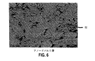
図5及び6についてより詳しく言うと、カソード及びアノードのバルク層部分44及び52の実施態様の微細構造が示される。示されるように、これらのバルク層部分の平均の粒の大きさは、示される例に関して典型的には約30〜100μmの範囲内である。
More specifically with respect to FIGS. 5 and 6, the microstructure of an embodiment of the cathode and anode
図7について言うと、特に電解質層48、カソード機能層46及びアノード機能層50を含む燃料電池の選択された部分が示される。カソード機能層46を図5に示されるカソードバルク層部分と比較すると、同様の微細構造を示すが、より微細な規模の粒を有し、平均の粒の大きさは10〜40μm程度である。
Referring to FIG. 7, selected portions of the fuel cell are shown, including in particular the electrolyte layer 48, the cathode functional layer 46, and the anode
1つの実施態様の特定の特徴によれば、SOFC構成体を形成するための処理の際、焼結が実施され、凝集原料から形成された電極の少なくとも1つが焼結の際に適度な収縮を受け、焼結された層が残留気孔、一般に相互に連結された気孔から形成される残留気孔を有するようにされる。定量化するため、典型的には凝集粉末から構成されるグリーン状態の電極から焼結後の最終的な電極への密度の変化は、ρs−ρgによって規定され、それは約0.3以下、例えば、0.2以下であり、ここで、ρsは相対焼結密度を表し、ρgは相対成形密度を表す。「相対」密度という用語の使用は当技術分野で十分理解されており、それは1.0の密度を有する100%高密度材料の分数である。典型的な相対成形密度値ρgは0.4〜0.5の範囲にあり、典型的な相対焼結密度値ρsは0.6〜0.7の範囲にある。1つの実施態様によれば、このような適度な収縮率は、上記の焼成プロセスを通して形成される凝集粉末の利用を通して達成され、それによりセル又は複数のセルから構成されるSOFC構成体の焼結の際の収縮を制限する。注目すべきことには、焼結された層の残留気孔は、不堅牢な気孔形成剤を使用又はそれに依存することなしに形成することができる。不堅牢な気孔形成剤は、グリーン状態の層のマトリクス全体に分布される材料として本明細書で規定され、それは処理の際に除去される。この除去は、例えば、揮発によって達成することができる。1つの態様によれば、このような不堅牢な気孔形成剤には依存せず、残留気孔は、適度な緻密化及び焼結の際の気孔の保持、特にグリーン状態からの顕著な粒内気孔の保持の結果である。 According to a particular feature of one embodiment, sintering is performed during the process to form the SOFC component, and at least one of the electrodes formed from the agglomerated raw material has a moderate shrinkage during sintering. The received and sintered layer is made to have residual pores, generally formed from interconnected pores. For quantification, the change in density from the green state electrode, typically composed of aggregated powder, to the final electrode after sintering is defined by ρs−ρg, which is about 0.3 or less, for example 0.2 or less, where ρs represents the relative sintered density and ρg represents the relative molding density. The use of the term “relative” density is well understood in the art and is a fraction of 100% dense material with a density of 1.0. Typical relative forming density values ρg are in the range of 0.4 to 0.5, and typical relative sintered density values ρs are in the range of 0.6 to 0.7. According to one embodiment, such moderate shrinkage is achieved through the use of agglomerated powder formed through the firing process described above, thereby sintering a SOFC structure comprised of a cell or cells. Limit the shrinkage during Notably, the residual pores in the sintered layer can be formed without using or relying on non-rigid pore formers. A non-rigid pore former is defined herein as a material that is distributed throughout the matrix of the green state layer, which is removed during processing. This removal can be achieved, for example, by volatilization. According to one embodiment, independent of such an insecure pore-forming agent, residual pores are suitable for densification and retention of pores during sintering, particularly significant intragranular pores from the green state. Is the result of the retention of
下表3は、図1の工程101〜109及び117に従って、そして表2に与えられる材料及び処理条件を用いて処理されたバルクカソード及びバルクアノードの成形及び焼結密度をまとめたものである。 Table 3 below summarizes the molding and sintering density of bulk cathodes and bulk anodes processed according to steps 101-109 and 117 of FIG. 1 and using the materials and processing conditions given in Table 2.
本発明の実施態様のさらに別の態様によれば、電極の少なくとも1つを形成するのに凝集原料を使用することで、得られる電極は、各機能層部分及び/又はバルク層部分の少なくとも1つに二峰性の気孔サイズ分布を有する。 According to yet another aspect of embodiments of the present invention, by using an agglomerated raw material to form at least one of the electrodes, the resulting electrode is at least one of each functional layer portion and / or bulk layer portion. It has a bimodal pore size distribution.
図6について言うと、比較的微細な粒内気孔がアノードバルク層部分52の粒内に与えられ、粒間気孔として本明細書で記載される非常により大きな気孔がアノードバルク層部分52の粒の間に画定されていることを見ることができる。一般的には、微細な、一般に粒内の気孔と、粗い、一般に粒間の気孔との間の平均気孔サイズにおける差はかなり大きい。定量的には、微細な気孔は平均気孔サイズPfを有し、粗い気孔は平均気孔サイズPcを有し、Pc/Pfは一般に約2.0以上、例えば、約5.0以上、例えば、約5.0以上又は約10.0以上(微細な気孔と粗い気孔の間で平均気孔サイズにおいて少なくとも一桁の差があることを表す)である。
Speaking of FIG 6, relatively fine intragranular pores of the anode
実際、バルクアノード構成体の二峰性の気孔サイズ分布が定量され、図7に示される。図7は、図1の工程101〜109及び117に従って、そして表2に示される処理条件及び材料を用いて処理された例の水銀細孔分布測定(mercury porisometry)による気孔分布を示す。示されるように、平均気孔サイズPcは7μmであり、平均微細気孔サイズPfは0.2μmであり、Pc/Pf比は35である。 In fact, the bimodal pore size distribution of the bulk anode structure has been quantified and is shown in FIG. FIG. 7 shows the pore distribution by mercury porisometry of an example processed according to steps 101-109 and 117 of FIG. 1 and using the processing conditions and materials shown in Table 2. As shown, the average pore size P c is 7 μm, the average fine pore size P f is 0.2 μm, and the P c / P f ratio is 35.
図8について言うと、カソードバルク層部分44だけでなく、カソード機能層部分46も二峰性の気孔サイズ分布を有することがさらに認められる。機能層部分に関して、微細な気孔は、「三重点」部位の数を増加させることによって機能性を改善することに寄与することができる。本明細書で用いられる場合には、「三重点」とは、電解質層46と、気孔(ガス)と、電極材料(例えば、カソードの場合のLSM)との間の交差の領域を表す。
Referring to FIG. 8, it is further recognized that not only the cathode
さらに別の実施態様によれば、電極の少なくとも1つは、二峰性の粒の大きさ分布、特には約1.5以上のGc/Gfによって定量される二峰性の粒の大きさ分布を有し、Gfは微細粒子の平均の粒子の大きさを表し、Gcは粗粒の平均の粒の大きさを表す。幾つかの実施態様によれば、Gc/Gfは、一般に約2.0以上、例えば、2.2以上又は約2.5以上である。他の実施態様は、粒の大きさの非常により大きな差を有することができ、例えば、約3.0以上又は約5.0以上である。上記の粗粒/微細粒の比は、凝集された機能層材料を利用する実施態様に関して特に好適である。上記のような未凝集粉末などの比較的より微細な機能層材料を利用する実施態様は、粒の大きさにおいて非常により大きな差、例えば、約10.0以上、例えば、約15.0以上、約20.0以上又は25.0以上のGc/Gfを有することができる。この点において、一般的には、二峰性の粒の大きさ分布は、同じ電極の機能層部分の平均の粒の大きさに対する電極のバルク層部分の平均の粒の大きさとして規定される。即ち、二峰性の粒の大きさ分布は、各バルク及び機能層部分の平均の粒の大きさを比較することによって典型的に定量される。 According to yet another embodiment, at least one of the electrodes, bimodal particle size distribution, in particular the size distribution of the bimodal particle to be quantified by about 1.5 or more Gc / Gf has, Gf represents the average size of the fine particles, Gc represents the grain size of the average coarse particle. According to some embodiments, Gc / Gf is generally about 2.0 or greater, such as 2.2 or greater, or about 2.5 or greater. Other embodiments can have a much larger difference in grain size , for example, about 3.0 or more, or about 5.0 or more. The ratio of the coarse / fine particle is particularly preferred with respect to embodiments utilizing agglomerated functional layer materials. Embodiments that utilize relatively finer functional layer materials, such as unagglomerated powders as described above, have a much larger difference in grain size , such as about 10.0 or more, such as about 15.0 or more, It can have a Gc / Gf of about 20.0 or greater or 25.0 or greater. In this regard, in general, the size distribution of the bimodal particle is defined as the average grain size of the average grain of the electrode to size the bulk layer portion of the functional layer portion of the same electrode . That is, the bimodal grain size distribution is typically quantified by comparing the average grain size of each bulk and functional layer portion.
表2を参照すると、ここに記載された構造は、75〜106μmの平均の粒の大きさを有するバルクカソード層と、25〜45μmの平均の粒の大きさを有するカソード機能層とを有し、約1.7(75μm/45μm)〜約4.2(106μm/25μm)の範囲内のGc/Gf比を与える。同様に、アノード層のGc/Gf比は約3.3である。 Referring to Table 2, the structure described herein has a bulk cathode layer having an average grain size of the 75~106Myuemu, and a cathode functional layer having an average grain size of 25~45μm A Gc / Gf ratio in the range of about 1.7 (75 μm / 45 μm) to about 4.2 (106 μm / 25 μm). Similarly, the Gc / Gf ratio of the anode layer is about 3.3.
上記のとおり、幾つかの実施態様では、比較的微細な機能層、カソード機能層とアノード機能層の一方又は両方が用いられる。特定の例では、以下の材料及び条件に従って処理された。 As noted above, in some embodiments, a relatively fine functional layer, one or both of a cathode functional layer and an anode functional layer are used. In a particular example, it was processed according to the following materials and conditions.
NiO/YSZのアノードバルク材料を1400℃で2時間焼成し、粉砕して150μm以下の大きさにした。未凝集の形態のアノード機能材料を、0.6μmのd50を有する15wt%のYSZ、0.25μmのd50を有する31wt%のYSZ、及び2.0μmのd50を有するNiOから構成した。 The NiO / YSZ anode bulk material was fired at 1400 ° C. for 2 hours and pulverized to a size of 150 μm or less. The unagglomerated form of the anode functional material was composed of 15 wt% YSZ having a d 50 of 0.6 μm, 31 wt% YSZ having a d 50 of 0.25 μm, and NiO having a d 50 of 2.0 μm.
LSMのカソードバルク材料を1400℃で2時間焼成し、粉砕して75〜106μmの大きさにした。1:1の比のLSMとSDCを1050℃で焼成し、45μm以下の大きさにした。 The LSM cathode bulk material was fired at 1400 ° C. for 2 hours and crushed to a size of 75-106 μm. A 1: 1 ratio of LSM and SDC was fired at 1050 ° C. to a size of 45 μm or less.
電解質材料は、0.75wt%のAl2O3ドープYSZ粉末から構成した。 The electrolyte material was composed of 0.75 wt% Al 2 O 3 doped YSZ powder.
アノード材料、カソード材料及び電解質材料をテープ成形して層を形成した。アノード機能層テープ、電解質テープ及びカソード機能層テープを10000psiの圧力下において105℃で積層した。その後、アノード機能層テープ、電解質テープ及びカソード機能層テープから構成されるプレスされた積層体を金型内のカソードバルク材料上に配置し、そしてプレスされた積層体上にアノードバルク材料を配置することによってグリーン状態のSOFCセルを形成した。次いで、形成されたグリーン状態の構造体をホットプレスすることで高密度化を実施した。 The anode material, cathode material and electrolyte material were taped to form a layer. The anode functional layer tape, electrolyte tape and cathode functional layer tape were laminated at 105 ° C. under a pressure of 10,000 psi. Thereafter, a pressed laminate composed of the anode functional layer tape, the electrolyte tape and the cathode functional layer tape is placed on the cathode bulk material in the mold, and the anode bulk material is placed on the pressed laminate. As a result, a green state SOFC cell was formed. Next, the formed green structure was hot pressed to increase the density.
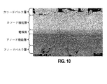
得られた構造体を図9に示し、それは破砕して研磨した部分であり、SOFCセルの構成層を示している。図10は図9の分解図であり、バルク電極層と各機能層との間での粒の大きさの顕著な相違を明確に示している。 The resulting structure is shown in FIG. 9, which is a crushed and polished part, showing the constituent layers of the SOFC cell. FIG. 10 is an exploded view of FIG. 9 and clearly shows a significant difference in grain size between the bulk electrode layer and each functional layer.
比較のために、カソード802、電解質808及びアノード810を有する最先端の燃料電池800を示す図11に注目されたい。示されるように、カソード802は、カソードバルク層部分804とカソード機能層部分806を含む。カソード802の平均の粒の大きさは一般に約1〜4μmの範囲内にあり、カソードのバルク層部分と機能層部分の間の粒の大きさの差は明らかに小さい。図11に示される従来技術の構造は、カソード中の不堅牢な成分が揮発され、従来の非焼成の微粒(凝集していない)原料が処理に利用されるサブトラクティブ法(subtractive process)によって形成されたと考えられる。
For comparison, note FIG. 11 showing a state-of-the-
上で開示した主題は、例示的なものであって、限定的なものではないとみなされるべきであり、特許請求の範囲が、本発明の真の範囲に含まれるすべての変更、強化及び他の実施態様を包含するものである。したがって、法律で認められる最大限の範囲まで、本発明の範囲は、特許請求の範囲及びその等価物の許される最も広い解釈によって決定されるべきであり、上記の詳しい説明によって制限又は限定されるべきではない。 The subject matter disclosed above is to be regarded as illustrative and not restrictive, and all modifications, enhancements and others that fall within the true scope of the claims are included in the claims. The embodiments are intended to be included. Therefore, to the fullest extent permitted by law, the scope of the present invention should be determined by the broadest allowable interpretation of the claims and their equivalents, and is limited or limited by the foregoing detailed description. Should not.
Claims (5)
該第1電極を覆う電解質と、
該電解質を覆う第2電極と
を含み、該第2電極がバルク層部分と機能層部分を含み、該機能層部分が前記電解質と前記第2電極のバルク層部分との間に延びる界面層であり、該機能層部分が二峰性の気孔サイズ分布を有し、該バルク層部分が該機能層部分よりも大きな平均粒径を有する共に、二峰性の気孔サイズ分布を有し、該バルク層部分が、微細な気孔と該微細な気孔よりも大きな粗い気孔を含み、該微細な気孔が粒内の気孔であり、該粗い気孔が粒間の気孔であり、
該第2電極は、微細粒の平均の粒の大きさをGfで表し、粗粒の平均の粒の大きさをGcで表すとき、Gc/Gf比は、1.5以上である二峰性の粒の大きさ分布を示し、そして、該バルク層部分と該機能層部分とは凝集粒を含む、SOFC構成体。 A first electrode;
An electrolyte covering the first electrode;
A second electrode covering the electrolyte, the second electrode including a bulk layer portion and a functional layer portion, wherein the functional layer portion extends between the electrolyte and the bulk layer portion of the second electrode. The functional layer portion has a bimodal pore size distribution, the bulk layer portion has a larger average particle size than the functional layer portion, and has a bimodal pore size distribution, the bulk The layer portion includes fine pores and coarse pores larger than the fine pores, the fine pores are intragranular pores, and the coarse pores are intergranular pores,
Second electrode represents the grain size of the average of the fine grains Gf, when representing grain average size of coarse grains in Gc, Gc / Gf ratio bimodal less than 1.5 And a bulk layer portion and the functional layer portion comprising agglomerated grains.
Applications Claiming Priority (3)
| Application Number | Priority Date | Filing Date | Title |
|---|---|---|---|
| US75768606P | 2006-01-09 | 2006-01-09 | |
| US60/757,686 | 2006-01-09 | ||
| PCT/US2007/060279 WO2007082209A2 (en) | 2006-01-09 | 2007-01-09 | Fuel cell components having porous electrodes |
Publications (3)
| Publication Number | Publication Date |
|---|---|
| JP2009522748A JP2009522748A (en) | 2009-06-11 |
| JP2009522748A5 JP2009522748A5 (en) | 2013-10-31 |
| JP5498021B2 true JP5498021B2 (en) | 2014-05-21 |
Family
ID=38257103
Family Applications (1)
| Application Number | Title | Priority Date | Filing Date |
|---|---|---|---|
| JP2008549686A Expired - Fee Related JP5498021B2 (en) | 2006-01-09 | 2007-01-09 | Fuel cell assembly having porous electrodes |
Country Status (10)
| Country | Link |
|---|---|
| US (2) | US20070178366A1 (en) |
| EP (1) | EP1979964A2 (en) |
| JP (1) | JP5498021B2 (en) |
| KR (1) | KR101154217B1 (en) |
| CN (1) | CN101385169A (en) |
| AU (1) | AU2007204758B2 (en) |
| BR (1) | BRPI0706376A2 (en) |
| CA (1) | CA2636310A1 (en) |
| RU (1) | RU2008127752A (en) |
| WO (1) | WO2007082209A2 (en) |
Families Citing this family (37)
| Publication number | Priority date | Publication date | Assignee | Title |
|---|---|---|---|---|
| DE102005023048B4 (en) * | 2005-05-13 | 2011-06-22 | Forschungszentrum Jülich GmbH, 52428 | Process for the preparation of a cathode-electrolyte composite and a high-temperature fuel cell |
| WO2007118127A2 (en) * | 2006-04-05 | 2007-10-18 | Saint-Gobain Ceramics & Plastics, Inc. | A sofc stack having a high temperature bonded ceramic interconnect and method for making same |
| WO2009036454A2 (en) * | 2007-09-13 | 2009-03-19 | Velocys Inc. | Porous electrolessly deposited coatings |
| DE602007005808D1 (en) * | 2007-09-24 | 2010-05-20 | Inst Of Nuclear Energy Res Ato | A new synergistic process and formulation for producing a high integrity membrane electrode assembly for a solid oxide fuel cell |
| US20090148743A1 (en) * | 2007-12-07 | 2009-06-11 | Day Michael J | High performance multilayer electrodes for use in oxygen-containing gases |
| US8828618B2 (en) * | 2007-12-07 | 2014-09-09 | Nextech Materials, Ltd. | High performance multilayer electrodes for use in reducing gases |
| EP2117067B1 (en) * | 2008-05-09 | 2014-08-13 | Institute of Nuclear Energy Research | Control process for specific porosity/gas permeability of electrode layers of SOFC-MEA through combination of sintering and pore former technology |
| TWI373880B (en) * | 2008-10-16 | 2012-10-01 | Iner Aec Executive Yuan | Solid oxide fuel cell and manufacture method thereof |
| WO2010077945A2 (en) * | 2008-12-17 | 2010-07-08 | Saint-Gobain Ceramics & Plastics, Inc. | Co-doped ysz eletrolytes for solid oxide fuel cell stacks |
| US8367265B2 (en) * | 2008-12-17 | 2013-02-05 | Saint-Gobain Ceramics & Plastics, Inc. | Uniform gas distribution through channels of SOFC |
| EP2377191A4 (en) * | 2008-12-17 | 2013-05-22 | Saint Gobain Ceramics | Electrode gas channel supports and methods for forming internal channels |
| JP5539391B2 (en) * | 2008-12-31 | 2014-07-02 | サン−ゴバン セラミックス アンド プラスティクス,インコーポレイティド | Method for SOFC cathode and co-fired battery and stack |
| EP2333883A1 (en) * | 2009-11-18 | 2011-06-15 | Forschungszentrum Jülich Gmbh (FJZ) | Anode for a high temperature fuel cell and production of same |
| TWI411154B (en) * | 2010-07-23 | 2013-10-01 | Iner Aec Executive Yuan | Structure of double anode layers on a metal substrate for a solid oxide fuel cell and the production method thereof |
| WO2012068297A2 (en) * | 2010-11-16 | 2012-05-24 | Saint-Gobain Ceramics & Plastics, Inc. | Substantially flat single cells for sofc stacks |
| JP4932960B1 (en) | 2010-12-20 | 2012-05-16 | 日本碍子株式会社 | Solid oxide fuel cell |
| US8993191B2 (en) * | 2011-07-25 | 2015-03-31 | Bloom Energy Corporation | Measurement device for measuring voltages along a linear array of voltage sources |
| US20130093129A1 (en) * | 2011-10-07 | 2013-04-18 | Aravind Mohanram | Method of forming a solid oxide fuel cell |
| JP2015504588A (en) * | 2011-12-07 | 2015-02-12 | サン−ゴバン セラミックス アンド プラスティクス,インコーポレイティド | Solid oxide fuel cell product and formation method |
| KR20130123189A (en) * | 2012-05-02 | 2013-11-12 | 삼성전자주식회사 | Anode support for solid oxide fuel cell and manufacturing method thereof, and solid oxide fuel cell including the anode support |
| WO2013180299A1 (en) | 2012-05-31 | 2013-12-05 | 京セラ株式会社 | Cell, cell stack device, electrochemical module, and electro- chemical device |
| US20130344415A1 (en) * | 2012-06-25 | 2013-12-26 | Aravind Mohanram | Solid oxide fuel cell and method of forming |
| KR101334899B1 (en) * | 2012-08-16 | 2013-11-29 | 국립대학법인 울산과학기술대학교 산학협력단 | Cathode for solid oxide fuel cell, method for producing thereof and fuel cell comprising the same |
| JP6152171B2 (en) * | 2012-12-18 | 2017-06-21 | サン−ゴバン セラミックス アンド プラスティクス,インコーポレイティド | Powder mixture for layers in solid oxide fuel cells |
| CN103529103A (en) * | 2013-10-25 | 2014-01-22 | 郑龙华 | Multilayer composite porous electrode of oxygen sensor and manufacturing method of electrode |
| WO2016043315A1 (en) * | 2014-09-19 | 2016-03-24 | 大阪瓦斯株式会社 | Electrochemical element, cell for solid oxide fuel cell, and preparation methods for these |
| KR102552154B1 (en) | 2018-06-01 | 2023-07-05 | 현대자동차주식회사 | manufacturing device of membrane electrode assembly with excellent mass transfer characteristics and durability, and method using thereof |
| US11424469B2 (en) | 2018-11-30 | 2022-08-23 | ExxonMobil Technology and Engineering Company | Elevated pressure operation of molten carbonate fuel cells with enhanced CO2 utilization |
| KR102610184B1 (en) | 2018-11-30 | 2023-12-04 | 퓨얼셀 에너지, 인크 | Fuel cell staging for molten carbonate fuel cells |
| WO2020112806A1 (en) * | 2018-11-30 | 2020-06-04 | Exxonmobil Research And Engineering Company | Layered cathode for molten carbonate fuel cell |
| JP7258144B2 (en) | 2018-11-30 | 2023-04-14 | フュエルセル エナジー, インコーポレイテッド | Reforming catalyst pattern for fuel cells operating with enhanced CO2 utilization |
| WO2020112812A1 (en) | 2018-11-30 | 2020-06-04 | Exxonmobil Research And Engineering Company | Operation of molten carbonate fuel cells with enhanced co 2 utilization |
| KR20210107700A (en) | 2018-11-30 | 2021-09-01 | 퓨얼 셀 에너지, 인크 | Regeneration of Molten Carbonate Fuel Cells for Deep CO2 Capture |
| JP7170559B2 (en) * | 2019-02-25 | 2022-11-14 | 太陽誘電株式会社 | Fuel cell and manufacturing method thereof |
| CN111769296B (en) * | 2019-03-27 | 2022-03-25 | 景德镇陶瓷大学 | Preparation method of SOFC (solid oxide Fuel cell) carbon deposition resistant Ni-YSZ (yttria stabilized zirconia) anode material |
| AU2019476660B2 (en) | 2019-11-26 | 2023-09-14 | ExxonMobil Technology and Engineering Company | Operation of molten carbonate fuel cells with high electrolyte fill level |
| JP2023503995A (en) | 2019-11-26 | 2023-02-01 | エクソンモービル・テクノロジー・アンド・エンジニアリング・カンパニー | Fuel cell module assembly and system using same |
Family Cites Families (96)
| Publication number | Priority date | Publication date | Assignee | Title |
|---|---|---|---|---|
| US3404040A (en) * | 1965-06-29 | 1968-10-01 | Gen Electric | Article comprising stabilized zirconia and a current collector embedded therein |
| US4000006A (en) * | 1975-09-02 | 1976-12-28 | United Technologies Corporation | Screen printing fuel cell electrolyte matrices |
| JPS5916831B2 (en) * | 1978-07-24 | 1984-04-18 | 日産自動車株式会社 | Manufacturing method of membrane structure type oxygen sensor |
| US4732637A (en) * | 1983-04-11 | 1988-03-22 | Engelhard Corporation | Method of fabricating an integral gas seal for fuel cell gas distribution assemblies |
| US4505992A (en) * | 1983-04-11 | 1985-03-19 | Engelhard Corporation | Integral gas seal for fuel cell gas distribution assemblies and method of fabrication |
| US4605602A (en) * | 1984-08-27 | 1986-08-12 | Engelhard Corporation | Corrosion protected, multi-layer fuel cell interface |
| US4913982A (en) * | 1986-12-15 | 1990-04-03 | Allied-Signal Inc. | Fabrication of a monolithic solid oxide fuel cell |
| JPS63254669A (en) * | 1987-04-10 | 1988-10-21 | Toray Ind Inc | Electrode substrate for fuel cell |
| US4799936A (en) * | 1987-06-19 | 1989-01-24 | Combustion Engineering, Inc. | Process of forming conductive oxide layers in solid oxide fuel cells |
| EP0378812A1 (en) * | 1989-01-18 | 1990-07-25 | Asea Brown Boveri Ag | Arrangement of fuel cells based on a solid electrolyte operating at a high temperature, consisting of zirconium oxide, to obtain maximum possible power |
| US4997726A (en) * | 1989-02-15 | 1991-03-05 | Sanyo Electric Co., Ltd. | Solid oxide electrolyte fuel cell |
| JPH0436963A (en) * | 1990-06-01 | 1992-02-06 | Fuji Electric Co Ltd | Manufacture of fuel cell with solid electrolyte |
| US5069987A (en) * | 1990-07-06 | 1991-12-03 | Igr Enterprises, Inc. | Solid oxide fuel cell assembly |
| JPH07118327B2 (en) * | 1990-07-07 | 1995-12-18 | 日本碍子株式会社 | Solid oxide fuel cell and porous electrode body used therefor |
| JPH04162365A (en) * | 1990-10-25 | 1992-06-05 | Tanaka Kikinzoku Kogyo Kk | Method for preparing electrode of fuel cell |
| JPH0748378B2 (en) * | 1991-03-28 | 1995-05-24 | 日本碍子株式会社 | Air electrode for solid electrolyte fuel cell and solid electrolyte fuel cell having the same |
| US5292599A (en) * | 1991-09-27 | 1994-03-08 | Ngk Insulators, Ltd. | Cell units for solid oxide fuel cells and power generators using such cell units |
| GB9211993D0 (en) * | 1992-06-05 | 1992-07-22 | British Nuclear Fuels Plc | Fuel cells |
| JP3246678B2 (en) * | 1992-07-31 | 2002-01-15 | 三井造船株式会社 | Method for manufacturing electrode body of solid oxide fuel cell |
| US5273837A (en) * | 1992-12-23 | 1993-12-28 | Corning Incorporated | Solid electrolyte fuel cells |
| US5604048A (en) * | 1993-02-26 | 1997-02-18 | Kyocera Corporation | Electrically conducting ceramic and fuel cell using the same |
| JP3267034B2 (en) * | 1993-03-10 | 2002-03-18 | 株式会社村田製作所 | Method for manufacturing solid oxide fuel cell |
| CA2161957C (en) * | 1993-03-20 | 2004-02-24 | Kevin Kendall | Solid oxide fuel cell structures |
| JPH06302330A (en) * | 1993-04-19 | 1994-10-28 | Mitsubishi Heavy Ind Ltd | Solid electrolyte type electrolytic cell |
| JPH0757737A (en) * | 1993-08-19 | 1995-03-03 | Mitsubishi Heavy Ind Ltd | Flame splaying electrode material of solid electrolyte type electrolytic cell |
| US5589285A (en) * | 1993-09-09 | 1996-12-31 | Technology Management, Inc. | Electrochemical apparatus and process |
| GB9403234D0 (en) * | 1994-02-19 | 1994-04-13 | Rolls Royce Plc | A solid oxide fuel cell stack and a reactant distribution member therefor |
| GB9403198D0 (en) * | 1994-02-19 | 1994-04-13 | Rolls Royce Plc | A solid oxide fuel cell stack |
| JPH0817451A (en) * | 1994-06-29 | 1996-01-19 | Aisin Seiki Co Ltd | Fuel cell |
| US6316138B1 (en) * | 1994-07-11 | 2001-11-13 | Mitsubishi, Jukogyo Kabushiki Kaisha | Solid oxide electrolyte fuel cell |
| US5992486A (en) * | 1994-09-13 | 1999-11-30 | Gunze Limited | Laminate gas barrier layer for pneumatic tires |
| US5601937A (en) * | 1995-01-25 | 1997-02-11 | Westinghouse Electric Corporation | Hydrocarbon reformer for electrochemical cells |
| AUPN173595A0 (en) * | 1995-03-15 | 1995-04-06 | Ceramic Fuel Cells Limited | Fuel cell interconnect device |
| EP0756347B1 (en) * | 1995-07-28 | 1999-03-24 | Nippon Telegraph And Telephone Corporation | Solid oxide fuel cell |
| NL1002318C1 (en) * | 1995-09-11 | 1997-03-13 | Stichting Tech Wetenschapp | Method of manufacturing a lithium battery. |
| US5993986A (en) * | 1995-11-16 | 1999-11-30 | The Dow Chemical Company | Solide oxide fuel cell stack with composite electrodes and method for making |
| US5753385A (en) * | 1995-12-12 | 1998-05-19 | Regents Of The University Of California | Hybrid deposition of thin film solid oxide fuel cells and electrolyzers |
| US5716664A (en) * | 1995-12-22 | 1998-02-10 | Marchetti; George A. | Method of making a hydrophilic, graphite electrode membrane assembly |
| DK0788175T3 (en) * | 1996-02-02 | 2000-07-10 | Sulzer Hexis Ag | High temperature fuel cell with a thin film electrolyte |
| JP3215650B2 (en) * | 1996-05-23 | 2001-10-09 | 日本碍子株式会社 | Electrochemical cell, method for producing the same, and electrochemical device |
| CA2275229C (en) * | 1996-12-20 | 2008-11-18 | Tokyo Gas Co., Ltd. | Fuel electrode of solid oxide fuel cell and process for the production of the same |
| US6228520B1 (en) * | 1997-04-10 | 2001-05-08 | The Dow Chemical Company | Consinterable ceramic interconnect for solid oxide fuel cells |
| US6099985A (en) * | 1997-07-03 | 2000-08-08 | Gas Research Institute | SOFC anode for enhanced performance stability and method for manufacturing same |
| JP3720539B2 (en) * | 1997-07-16 | 2005-11-30 | 株式会社フジクラ | Fuel electrode material for solid oxide fuel cell and fuel electrode film forming method using the same |
| US5902691A (en) * | 1997-10-27 | 1999-05-11 | Ut Automotive Dearborn, Inc. | Fuel cell with shared space for electrode assembly |
| US6051329A (en) * | 1998-01-15 | 2000-04-18 | International Business Machines Corporation | Solid oxide fuel cell having a catalytic anode |
| JP2000034167A (en) * | 1998-07-17 | 2000-02-02 | Toto Ltd | Nickel-/zirconia based composite powder and its production |
| EP1081778A4 (en) * | 1998-04-21 | 2006-03-01 | Toto Ltd | Solid electrolyte fuel cell and method of producing the same |
| US6093500A (en) * | 1998-07-28 | 2000-07-25 | International Fuel Cells Corporation | Method and apparatus for operating a fuel cell system |
| US6117302A (en) * | 1998-08-18 | 2000-09-12 | Aluminum Company Of America | Fuel cell aluminum production |
| JP3230156B2 (en) * | 1999-01-06 | 2001-11-19 | 三菱マテリアル株式会社 | Electrode of solid oxide fuel cell and method of manufacturing the same |
| KR100341402B1 (en) * | 1999-03-09 | 2002-06-21 | 이종훈 | Single Cell and Stack Structure of Solid Oxide Fuel Cell |
| US6399233B1 (en) * | 1999-07-29 | 2002-06-04 | Technology Management, Inc. | Technique for rapid cured electrochemical apparatus component fabrication |
| US6605316B1 (en) * | 1999-07-31 | 2003-08-12 | The Regents Of The University Of California | Structures and fabrication techniques for solid state electrochemical devices |
| US6682842B1 (en) * | 1999-07-31 | 2004-01-27 | The Regents Of The University Of California | Composite electrode/electrolyte structure |
| KR100344936B1 (en) * | 1999-10-01 | 2002-07-19 | 한국에너지기술연구원 | Tubular Solid Oxide Fuel Cell supported by Fuel Electrode and Method for the same |
| US6649296B1 (en) * | 1999-10-15 | 2003-11-18 | Hybrid Power Generation Systems, Llc | Unitized cell solid oxide fuel cells |
| WO2001048855A1 (en) * | 1999-12-28 | 2001-07-05 | Corning Incorporated | Honeycomb electrode fuel cells |
| US6485852B1 (en) * | 2000-01-07 | 2002-11-26 | Delphi Technologies, Inc. | Integrated fuel reformation and thermal management system for solid oxide fuel cell systems |
| DK174654B1 (en) * | 2000-02-02 | 2003-08-11 | Topsoe Haldor As | Solid oxide fuel cell and its applications |
| US6428920B1 (en) * | 2000-05-18 | 2002-08-06 | Corning Incorporated | Roughened electrolyte interface layer for solid oxide fuel cells |
| US6309769B1 (en) * | 2000-06-30 | 2001-10-30 | Plug Power Inc. | Carbon monoxide filter layer |
| JP4605885B2 (en) * | 2000-10-23 | 2011-01-05 | 東邦瓦斯株式会社 | Support membrane type solid oxide fuel cell |
| US6551734B1 (en) * | 2000-10-27 | 2003-04-22 | Delphi Technologies, Inc. | Solid oxide fuel cell having a monolithic heat exchanger and method for managing thermal energy flow of the fuel cell |
| JP2004513500A (en) * | 2000-11-08 | 2004-04-30 | グローバル サーモエレクトリック インコーポレイテッド | Electrochemical battery coupling device |
| US6803141B2 (en) * | 2001-03-08 | 2004-10-12 | The Regents Of The University Of California | High power density solid oxide fuel cells |
| US7638222B2 (en) * | 2001-03-28 | 2009-12-29 | Hexis Ag | Porous, gas permeable layer substructure for a thin, gas tight layer for use as a functional component in high temperature fuel cells |
| US6780534B2 (en) * | 2001-04-11 | 2004-08-24 | Donaldson Company, Inc. | Filter assembly for intake air of fuel cell |
| US6677070B2 (en) * | 2001-04-19 | 2004-01-13 | Hewlett-Packard Development Company, L.P. | Hybrid thin film/thick film solid oxide fuel cell and method of manufacturing the same |
| US20020155227A1 (en) * | 2001-04-23 | 2002-10-24 | Sulzer Markets And Technolgy Ag | Method for the manufacture of a functional ceramic layer |
| FR2826956B1 (en) * | 2001-07-04 | 2004-05-28 | Air Liquide | PROCESS FOR PREPARING A LOW THICKNESS CERAMIC COMPOSITION WITH TWO MATERIALS, COMPOSITION OBTAINED, ELECTROCHEMICAL CELL AND MEMBRANE COMPRISING IT |
| JP4840718B2 (en) * | 2001-08-14 | 2011-12-21 | 日産自動車株式会社 | Solid oxide fuel cell |
| AU2002359273A1 (en) * | 2001-10-17 | 2003-04-28 | Trustees Of Boston University | One-step consolidation process for manufacturing solid oxide fuel cells |
| US6949307B2 (en) * | 2001-10-19 | 2005-09-27 | Sfco-Efs Holdings, Llc | High performance ceramic fuel cell interconnect with integrated flowpaths and method for making same |
| US6653009B2 (en) * | 2001-10-19 | 2003-11-25 | Sarnoff Corporation | Solid oxide fuel cells and interconnectors |
| US7008709B2 (en) * | 2001-10-19 | 2006-03-07 | Delphi Technologies, Inc. | Fuel cell having optimized pattern of electric resistance |
| JP2003132906A (en) * | 2001-10-24 | 2003-05-09 | Nissan Motor Co Ltd | Single cell for fuel cell and solid electrolytic fuel cell |
| US8114551B2 (en) * | 2002-03-04 | 2012-02-14 | Sulzer Hexis Ag | Porous structured body for a fuel cell anode |
| YU88103A (en) * | 2002-05-14 | 2006-08-17 | H.Lundbeck A/S. | Treatment adhd |
| JP2004055194A (en) | 2002-07-17 | 2004-02-19 | Mitsubishi Materials Corp | Electrode of solid oxide type fuel cell |
| JP2004087415A (en) * | 2002-08-29 | 2004-03-18 | Araco Corp | Electrode substrate for fuel cell and its manufacturing method |
| US6869201B2 (en) * | 2002-09-27 | 2005-03-22 | Stephen M. Kruger | Reflective flashlight holder |
| CN1276537C (en) * | 2002-10-28 | 2006-09-20 | 韩国电力公社 | Solid oxide fuel cells having gas channel |
| US6893769B2 (en) * | 2002-12-18 | 2005-05-17 | Hewlett-Packard Development Company, L.P. | Fuel cell assemblies and methods of making the same |
| JP2004200125A (en) * | 2002-12-20 | 2004-07-15 | Hosokawa Funtai Gijutsu Kenkyusho:Kk | Electrode material, fuel electrode for solid oxide fuel cell, and the solid oxide fuel cell |
| EP1624521B1 (en) * | 2003-03-31 | 2013-04-24 | Tokyo Gas Company Limited | Method for fabricating solid oxide fuel cell module |
| US7070879B2 (en) * | 2003-04-10 | 2006-07-04 | Hewlett-Packard Development Company, L.P. | Fuel cell or electrodes with passive support |
| JP2004342555A (en) * | 2003-05-19 | 2004-12-02 | Nissan Motor Co Ltd | Electrode material for solid electrolyte fuel cell, its manufacturing method, and solid electrolyte fuel cell using it |
| AU2004252862B2 (en) * | 2003-06-09 | 2008-04-17 | Saint-Gobain Ceramics & Plastics, Inc. | Stack supported solid oxide fuel cell |
| US20050017055A1 (en) * | 2003-07-24 | 2005-01-27 | Kurz Douglas L. | Electrochemical fuel cell component materials and methods of bonding electrochemical fuel cell components |
| US7445814B2 (en) * | 2003-10-22 | 2008-11-04 | Hewlett-Packard Development Company, L.P. | Methods of making porous cermet and ceramic films |
| JP4430514B2 (en) * | 2003-11-05 | 2010-03-10 | 本田技研工業株式会社 | Electrolyte / electrode assembly and method for producing the same |
| JP5234698B2 (en) * | 2004-03-29 | 2013-07-10 | ヘクシス アクチェンゲゼルシャフト | Anode materials for high temperature fuel cells |
| US20060024547A1 (en) * | 2004-07-27 | 2006-02-02 | David Waldbillig | Anode supported sofc with an electrode multifunctional layer |
| WO2006125177A2 (en) * | 2005-05-19 | 2006-11-23 | Massachusetts Institute Of Technology | Electrode and catalytic materials |
| WO2007118127A2 (en) * | 2006-04-05 | 2007-10-18 | Saint-Gobain Ceramics & Plastics, Inc. | A sofc stack having a high temperature bonded ceramic interconnect and method for making same |
-
2007
- 2007-01-09 AU AU2007204758A patent/AU2007204758B2/en not_active Ceased
- 2007-01-09 CN CNA2007800052038A patent/CN101385169A/en active Pending
- 2007-01-09 US US11/621,447 patent/US20070178366A1/en not_active Abandoned
- 2007-01-09 CA CA002636310A patent/CA2636310A1/en not_active Abandoned
- 2007-01-09 JP JP2008549686A patent/JP5498021B2/en not_active Expired - Fee Related
- 2007-01-09 WO PCT/US2007/060279 patent/WO2007082209A2/en active Application Filing
- 2007-01-09 RU RU2008127752/09A patent/RU2008127752A/en not_active Application Discontinuation
- 2007-01-09 EP EP07710017A patent/EP1979964A2/en not_active Withdrawn
- 2007-01-09 KR KR1020087019575A patent/KR101154217B1/en not_active IP Right Cessation
- 2007-01-09 BR BRPI0706376-8A patent/BRPI0706376A2/en not_active IP Right Cessation
-
2013
- 2013-08-26 US US13/975,932 patent/US20130337360A1/en not_active Abandoned
Also Published As
| Publication number | Publication date |
|---|---|
| JP2009522748A (en) | 2009-06-11 |
| WO2007082209A3 (en) | 2008-03-20 |
| WO2007082209A2 (en) | 2007-07-19 |
| EP1979964A2 (en) | 2008-10-15 |
| CA2636310A1 (en) | 2007-07-19 |
| BRPI0706376A2 (en) | 2011-03-22 |
| US20070178366A1 (en) | 2007-08-02 |
| US20130337360A1 (en) | 2013-12-19 |
| CN101385169A (en) | 2009-03-11 |
| AU2007204758A1 (en) | 2007-07-19 |
| KR101154217B1 (en) | 2012-06-18 |
| RU2008127752A (en) | 2010-02-20 |
| KR20080105041A (en) | 2008-12-03 |
| AU2007204758B2 (en) | 2010-01-21 |
Similar Documents
| Publication | Publication Date | Title |
|---|---|---|
| JP5498021B2 (en) | Fuel cell assembly having porous electrodes | |
| JP2009522748A5 (en) | ||
| CA2785959C (en) | A sofc stack having a high temperature bonded ceramic interconnect and method for making same | |
| KR101586410B1 (en) | A powder containing elogated grains and the use thereof for producing an electrode for a solid oxide fuel cell | |
| RU2699815C2 (en) | Electrolyte formation method | |
| CN107223289B (en) | Method of forming an electrolyte | |
| WO2016080019A1 (en) | Anode for solid oxide fuel cell and manufacturing method therefor, and manufacturing method for electrolyte layer-electrode assembly for fuel cell | |
| US20040033886A1 (en) | Method for producing an electrode that has a temperature-stabilized conductivity | |
| Corbin et al. | Development of solid oxide fuel cell anodes using metal‐coated pore‐forming agents | |
| US20070042225A1 (en) | Supported ceramic membranes and electrochemical cells including the same | |
| KR101335063B1 (en) | Method of large powewr solid oxide fuel cell | |
| JPWO2011001930A1 (en) | Manufacturing method of electrolyte / electrode assembly | |
| KR101886321B1 (en) | metal-ceramic nanocomposites, method for manufacturing thereof | |
| MX2008008875A (en) | Fuel cell components having porous electrodes | |
| KR101276690B1 (en) | Solid oxide fuel cell having the improved electrodes and its preparation | |
| KR101346729B1 (en) | Anode support for sold oxide fuel cell and manufacturing methods thereof | |
| JP2010229004A (en) | Method for firing ceramic thin plate having large aspect ratio |
Legal Events
| Date | Code | Title | Description |
|---|---|---|---|
| A977 | Report on retrieval |
Free format text: JAPANESE INTERMEDIATE CODE: A971007 Effective date: 20120120 |
|
| A131 | Notification of reasons for refusal |
Free format text: JAPANESE INTERMEDIATE CODE: A131 Effective date: 20120131 |
|
| A601 | Written request for extension of time |
Free format text: JAPANESE INTERMEDIATE CODE: A601 Effective date: 20120427 |
|
| A602 | Written permission of extension of time |
Free format text: JAPANESE INTERMEDIATE CODE: A602 Effective date: 20120509 |
|
| A521 | Written amendment |
Free format text: JAPANESE INTERMEDIATE CODE: A523 Effective date: 20120725 |
|
| A131 | Notification of reasons for refusal |
Free format text: JAPANESE INTERMEDIATE CODE: A131 Effective date: 20120821 |
|
| A601 | Written request for extension of time |
Free format text: JAPANESE INTERMEDIATE CODE: A601 Effective date: 20121120 |
|
| A521 | Written amendment |
Free format text: JAPANESE INTERMEDIATE CODE: A523 Effective date: 20121220 |
|
| A601 | Written request for extension of time |
Free format text: JAPANESE INTERMEDIATE CODE: A601 Effective date: 20121220 |
|
| RD02 | Notification of acceptance of power of attorney |
Free format text: JAPANESE INTERMEDIATE CODE: A7422 Effective date: 20121220 |
|
| RD03 | Notification of appointment of power of attorney |
Free format text: JAPANESE INTERMEDIATE CODE: A7423 Effective date: 20121220 |
|
| A602 | Written permission of extension of time |
Free format text: JAPANESE INTERMEDIATE CODE: A602 Effective date: 20121212 Free format text: JAPANESE INTERMEDIATE CODE: A602 Effective date: 20121228 |
|
| A521 | Written amendment |
Free format text: JAPANESE INTERMEDIATE CODE: A523 Effective date: 20130110 |
|
| RD04 | Notification of resignation of power of attorney |
Free format text: JAPANESE INTERMEDIATE CODE: A7424 Effective date: 20121228 |
|
| A131 | Notification of reasons for refusal |
Free format text: JAPANESE INTERMEDIATE CODE: A131 Effective date: 20130514 |
|
| A601 | Written request for extension of time |
Free format text: JAPANESE INTERMEDIATE CODE: A601 Effective date: 20130813 |
|
| A602 | Written permission of extension of time |
Free format text: JAPANESE INTERMEDIATE CODE: A602 Effective date: 20130820 |
|
| A524 | Written submission of copy of amendment under section 19 (pct) |
Free format text: JAPANESE INTERMEDIATE CODE: A524 Effective date: 20130909 |
|
| A131 | Notification of reasons for refusal |
Free format text: JAPANESE INTERMEDIATE CODE: A131 Effective date: 20131029 |
|
| A521 | Written amendment |
Free format text: JAPANESE INTERMEDIATE CODE: A523 Effective date: 20140128 |
|
| TRDD | Decision of grant or rejection written | ||
| A01 | Written decision to grant a patent or to grant a registration (utility model) |
Free format text: JAPANESE INTERMEDIATE CODE: A01 Effective date: 20140225 |
|
| A61 | First payment of annual fees (during grant procedure) |
Free format text: JAPANESE INTERMEDIATE CODE: A61 Effective date: 20140307 |
|
| R150 | Certificate of patent or registration of utility model |
Ref document number: 5498021 Country of ref document: JP Free format text: JAPANESE INTERMEDIATE CODE: R150 |
|
| LAPS | Cancellation because of no payment of annual fees |