EP0706836B1 - Sifter frame for powder particle sifter - Google Patents
Sifter frame for powder particle sifter Download PDFInfo
- Publication number
- EP0706836B1 EP0706836B1 EP94308333A EP94308333A EP0706836B1 EP 0706836 B1 EP0706836 B1 EP 0706836B1 EP 94308333 A EP94308333 A EP 94308333A EP 94308333 A EP94308333 A EP 94308333A EP 0706836 B1 EP0706836 B1 EP 0706836B1
- Authority
- EP
- European Patent Office
- Prior art keywords
- sifter
- frame
- powder
- inner frame
- rough
- Prior art date
- Legal status (The legal status is an assumption and is not a legal conclusion. Google has not performed a legal analysis and makes no representation as to the accuracy of the status listed.)
- Expired - Lifetime
Links
- 239000000843 powder Substances 0.000 title claims description 133
- 239000002245 particle Substances 0.000 title claims description 14
- 238000007789 sealing Methods 0.000 claims description 4
- 238000007599 discharging Methods 0.000 claims description 2
- 239000011236 particulate material Substances 0.000 claims description 2
- 230000002093 peripheral effect Effects 0.000 claims description 2
- 238000005192 partition Methods 0.000 description 16
- 235000013312 flour Nutrition 0.000 description 12
- 239000000203 mixture Substances 0.000 description 9
- 238000000638 solvent extraction Methods 0.000 description 6
- 239000002023 wood Substances 0.000 description 6
- 230000003014 reinforcing effect Effects 0.000 description 3
- 238000009434 installation Methods 0.000 description 2
- 238000000034 method Methods 0.000 description 2
- 229910001220 stainless steel Inorganic materials 0.000 description 2
- 239000010935 stainless steel Substances 0.000 description 2
- 230000000881 depressing effect Effects 0.000 description 1
- 230000000994 depressogenic effect Effects 0.000 description 1
- 238000004519 manufacturing process Methods 0.000 description 1
- 238000003801 milling Methods 0.000 description 1
- 238000012986 modification Methods 0.000 description 1
- 230000004048 modification Effects 0.000 description 1
- 239000004745 nonwoven fabric Substances 0.000 description 1
- 238000003825 pressing Methods 0.000 description 1
- 238000000926 separation method Methods 0.000 description 1
Images




Classifications
-
- B—PERFORMING OPERATIONS; TRANSPORTING
- B07—SEPARATING SOLIDS FROM SOLIDS; SORTING
- B07B—SEPARATING SOLIDS FROM SOLIDS BY SIEVING, SCREENING, SIFTING OR BY USING GAS CURRENTS; SEPARATING BY OTHER DRY METHODS APPLICABLE TO BULK MATERIAL, e.g. LOOSE ARTICLES FIT TO BE HANDLED LIKE BULK MATERIAL
- B07B1/00—Sieving, screening, sifting, or sorting solid materials using networks, gratings, grids, or the like
- B07B1/46—Constructional details of screens in general; Cleaning or heating of screens
- B07B1/4609—Constructional details of screens in general; Cleaning or heating of screens constructional details of screening surfaces or meshes
- B07B1/4618—Manufacturing of screening surfaces
-
- B—PERFORMING OPERATIONS; TRANSPORTING
- B07—SEPARATING SOLIDS FROM SOLIDS; SORTING
- B07B—SEPARATING SOLIDS FROM SOLIDS BY SIEVING, SCREENING, SIFTING OR BY USING GAS CURRENTS; SEPARATING BY OTHER DRY METHODS APPLICABLE TO BULK MATERIAL, e.g. LOOSE ARTICLES FIT TO BE HANDLED LIKE BULK MATERIAL
- B07B1/00—Sieving, screening, sifting, or sorting solid materials using networks, gratings, grids, or the like
- B07B1/28—Moving screens not otherwise provided for, e.g. swinging, reciprocating, rocking, tilting or wobbling screens
- B07B1/38—Moving screens not otherwise provided for, e.g. swinging, reciprocating, rocking, tilting or wobbling screens oscillating in a circular arc in their own plane; Plansifters
-
- B—PERFORMING OPERATIONS; TRANSPORTING
- B07—SEPARATING SOLIDS FROM SOLIDS; SORTING
- B07B—SEPARATING SOLIDS FROM SOLIDS BY SIEVING, SCREENING, SIFTING OR BY USING GAS CURRENTS; SEPARATING BY OTHER DRY METHODS APPLICABLE TO BULK MATERIAL, e.g. LOOSE ARTICLES FIT TO BE HANDLED LIKE BULK MATERIAL
- B07B1/00—Sieving, screening, sifting, or sorting solid materials using networks, gratings, grids, or the like
- B07B1/46—Constructional details of screens in general; Cleaning or heating of screens
-
- B—PERFORMING OPERATIONS; TRANSPORTING
- B07—SEPARATING SOLIDS FROM SOLIDS; SORTING
- B07B—SEPARATING SOLIDS FROM SOLIDS BY SIEVING, SCREENING, SIFTING OR BY USING GAS CURRENTS; SEPARATING BY OTHER DRY METHODS APPLICABLE TO BULK MATERIAL, e.g. LOOSE ARTICLES FIT TO BE HANDLED LIKE BULK MATERIAL
- B07B2201/00—Details applicable to machines for screening using sieves or gratings
- B07B2201/02—Fastening means for fastening screens to their frames which do not stretch or sag the screening surfaces
Definitions
- the present invention relates to a sifter frame according to the preamble of claim 1 used as a sifter for separating the particle sizes of powder particles such as flour and the like, and more specifically, but not exclusively, to a structure of an intimate contact type sifter frame used by being stacked into multi-stages to sift and separate powder particles.
- Sifters are conventionally used to separate the particle sizes of powder particles such as flour and the like. The sifter will be described below with respect to the separation of the particle sizes of flour by way of example.
- Sifter types known as plan sifter, square sifter and the like are used in the flour milling industry from old times to separate the particle sizes of flour, and at present various types of sifters such as the modifications of the above sifters and intermediate type sifters (such as a junior type sifter and the like) are put into practical use. These sifters are fundamentally arranged such that powder having a small particle size in powder supplied onto the sifter is caused to pass through the sifter downwardly while a multiplicity of stacked sifter frames are caused to make a circular motion to separate the particle sizes of the supplied powder.
- a reason why the flour sifter is composed of the sifter frames stacked to the multi-stages as described above is to make the sifter area as large as possible, which is desirable to effectively separate flour by moving the flour on the surface of the sifter.
- the area of the sifter per unit area of installation is increased to save the installation area in such a manner that the sifter is composed to sifter frames stacked to the multi-stages and a sifter surface on which flour moves is formed so that the sifter surface vertically meanders in the sifter.
- the sifter is usually composed of a group of stacked square sifter frames tightened from the upper and lower sides thereof or a group of sifter frames which are stacked to ten to twenty stages and accommodated in a sifter frame box called a box so that they are horizontally tightened and fixed and also tightened and fixed from the upper side thereof. Then, the box and the like are driven by a drive unit composed of an eccentric shaft provided with a balance weight and a drive shaft to make a circular motion within a horizontal plane at high speed.
- sifter frame which has a structure for limiting a portion to be replaced only to a sifter net. That is, there are generally used a pair of a frame member of about 1 m x 1 m (referred to as an outer frame) and a frame member having a sifter net stretched therein as an object to be replaced (referred to as an inner frame) with the inner frame being engaged with the outer frame.
- the conventional type sifter frame shown in these figures has a combination type structure arranged such that a rectangular inner frame 500 (refer to FIG. 6) is fitted with in the inner frame fitting portion of an outer frame 600 (refer to FIG. 7), the inner frame 500 having a sifter net 501 stretched over the upper surface thereof to separate flour to powder on a sifter (rough powder) and powder below the sifter (through: fine powder), and the outer frame 600 being in contact with the three circumferential sides of the inner frame and having a longitudinal path in an upward/downward direction (refer to FIG. 8).
- the above inner frame 500 shown in FIG. 6 is composed of wood frame member 502 - 505 of, for example, wood for constituting a rectangular four-side frame and a sifter net 501 having a predetermined sifting mesh and stretched over reinforcing wood bars 506, 507 formed to a cross shape and disposed inwardly of the rectangular frame member.
- a crimp net having a rough mesh is usually stretched below the sifter net 501 in parallel therewith and a cleaner such as, for example, a triangular flat cleaner having a hemispheric projection is movably interposed between the upper and lower nets so that clogging of the sifter net 501 is prevented by causing the cleaner to beat the net when the sifter is in operation.
- a cleaner such as, for example, a triangular flat cleaner having a hemispheric projection
- the outer frame 600 shown in FIG. 7 is composed of an inner frame fitting portion within which the above inner frame 500 is fitted in contact with or biased to an outer side wall outer block member 610 as one of the four sides of the rectangular frame forming the outer block of the outer frame 600 and longitudinal paths 601, 602, 602 disposed outwardly of the inner frame fitting portion in an upward/downward direction along the inside of each of the remaining three sides except the side wall 610 of the above one side.
- the outer frame 600 is composed of a pair of parallel inner side walls (frame members) 607, 607 disposed to form the above inner frame fitting portion, three inner frame fitting stand frames 604, 605, 606 fixed over the lower surfaces of the inner side walls 607, 607.
- a pair of outer side walls 608, 608 is disposed separately to form the fine powder dropping ports 602, 602 to the outside of each of the above outer inside walls 607, 607, and the outer side wall 610 is disposed in contact with the outside of the inner frame fitting stand frame 606,
- An outer side wall 609 is separately disposed to form a rough powder dropping port 601 (usually, called an over port) outwardly of the inner frame fitting stand frame 604, and a receiving plate (fine powder flowing plate) 603 is provided as a bottom surface for introducing fine powder (through) having passed through the sifter net 501 of the inner frame to be fitted to the above right and left dropping ports 602, 602.
- the inner side walls 607, 607 are fixed to the outer side walls 608, 608 at suitable positions through intermediate brackets 613, 613, and the inner frame fitting stand frame 604 is fixed to the outer side wall 609 through an intermediate bracket 615 in the same way.
- Numeral 614 denotes blocks disposed at four corners to close the unnecessary space portions in the outer frame as well as to increase the strength of a fitting structure in an upward/downward direction.
- the receiving plate 603 is composed of a stainless steel sheet or the like fixed to the respective lower surfaces of the above inner frame fitting stand frames 604, 605, 606 by screws. With this arrangement, each of the right and left ends of the receiving plate 603 has a gap corresponding to the thickness of the stand frames 604, 605 between the lower surface of the inner side wall 607 and the receiving plate 603, and these gaps form slit-shaped fine powder dropping ports 617 for dropping fine powder dropped onto the receiving plate 603 into the right and left fine powder dropping ports 602. Note, the receiving plate 603 is disposed substantially at the intermediate position in the upward-downward direction of the sifter frame in a bottom-lifted-state (refer to FIG. 9).
- a direction in which a pair of the fine powder dropping ports 602 is separated from each other is referred to as a right/left direction and a direction orthogonal to the right/left direction in a horizontal direction is referred to as a forward/backward direction.
- a group of the sifter frames having the above arrangement can be constructed by stacking a multiplicity of the sifter frames in such a manner that the positions of the rough powder dropping ports 601 are successively reversed (alternately disposed) on the respective stages (refer to FIG. 9). Then, powder particles having moved (flown) on the sifter net 501 of a certain stage drop into the rough powder dropping port 501 of the inner frame 500 along the inclined surface 502a of the frame member 502 in contact with the rough powder dropping port 601 and moves onto the sifter net of the sifter frame of the next lower stage. Further, fine powder having passed through the sifter net 501 drops onto the receiving plate 603 and further drops into the fine powder dropping ports 602 through the right and left slit-shaped fine powder dropping port 617.
- press beams 620, 620 are disposed between the outer side walls 609, 610 below the receiving plate 603 of the outer frame 600 so that the press beams 620, 620 extend to the upper surfaces of the inner side wall 607 and the frame member 504 (or 505) of the inner frame of the lower stage sifter frame to cover them in contact therewith (refer to FIG. 9).
- the sifter is naturally required to securely prevent the mixture of rough powder with fine powder caused through the gap defined at the inner frame fitting position.
- the lower portion of the frame member 502 of the inner frame 500 is provided with a stepped portion as shown in FIG. 8 (b) and the stepped leg portion 502b is engaged with the stepped portion 604a of the inner frame fitting stand frame 604 formed in correspondence with the outer frame to form seal portions.
- FIG. 8 (a) is an unfolded view for explaining the relationship between the outer frame 600 and the inner frame 500 fitted therewith
- FIG. 9 is an unfolded view for explaining a state that the sifter frames each arranged as described above are stacked with the rough powder dropping ports 601 thereof successively disposed alternately.
- surfaces 700, 701 shown cross-hatched serve as seal surfaces for strongly pressing the inner frame 500 of the lower stage sifter frame downwardly by the upper stage sifter frame (outer frame 600) so as to increase the seal pressure of the above seal portions and at the same time to seal and partition a region (rough powder region) where rough powder flows from a region where fine powder flows (fine powder region).
- a suitable seal sheet is applied to the surfaces 700, 701 as necessary.
- the inventors have found the following fact by examining a cause of the mixture of rough powder with fine powder, taking the present state mentioned above into consideration. That is, there is a problem that although the mixture of rough powder with fine powder in the conventional sifter frame is not caused on the above seal surfaces 700, 701 which are in intimate contact with each other under pressure, the mixture of them is caused at the portion where the frame member 502 is fitted with the inner frame fitting stand frame 604.
- brackets 616 provided to form the inner frame fitting portion of the outer frame are engaged with the extreme (front) end surfaces (surfaces facing to the rough powder dropping port) 504a, 505a of the right and left frame members 504, 505 of the inner frame to seal a fine powder region and a rough powder region, no pressure is applied to make the intimate contact of the both surfaces of the fitting portion in the structure. More specifically, the direction of a horizontal force for causing the both surfaces to come into intimate contact with each other is different 90° from a vertical force for causing the upper and lower sifter frames to come into intimate contact with each other.
- the rough powder having entered the above gap further moves and enters the fine powder region as shown by dotted lines 802, 803, by which the aforesaid mixture is caused.
- Preferred embodiments of the present invention provide a novel powder separating sifter frame, alleviating the above various problems, and capable of reducing the storing volume by limiting the portion of the sifter frame to be prepared and stored, as well as satisfying a requirement for saving labor needed by a replacement job, and securely preventing the mixing of rough powder with fine powder, which has been sometimes caused by a conventional sifter frame.
- a sifter stage for being stacked with other similar stages to provide a multi-stage sifter for separating particulate material into sifted (fine) and non-sifted (rough) fractions, said sifter stage comprising:-
- the lower surface of the sifter frame stacked to the upper stage in such a manner that the lower surface extends to and air-tightly engages with both upper surfaces of the outer frame and the inner frame which are formed by being fitted with the sifter frame stacked to the lower stage.
- the weight and size of the inner frame can be reduced as compared with those of an inner frame arranged integrally as a whole.
- the seal surfaces for partitioning and sealing the rough powder region from the fine powder region are formed as the closed type rectangularly annular edges located on the same plane and an upward/downward intimate contact force acts on the seal surfaces, a strictly partitioned seal can be achieved which need not take the leakage between the rough powder region and the fine powder region into consideration.
- partitioning structure for partitioning the rough powder region from the fine powder region can be arranged by the frame members of the inner frame or the outer frame itself and these regions can be sealed only by the intimate contact of the horizontal seal surfaces which are engaged in an upward/downward direction, the above partitioning structure does not have the seal structure of prior art which contains a vertically sealed surface as shown in FIG 6 - FIG 10. Consequently, there can be obtained a good partitioned seal by which a possibility that rough powder is mixed with fine powder is securely prevented.
- numeral 405 denotes an inner frame which is composed of, for example, square column wood frame members 452 - 455 constituting a rectangular four-sided frame, a partition wall 458 for partitioning the inside of the rectangular four-side frame into a sifter net region 450 and a region for a rough powder dropping port 459.
- Reinforcing wood bars 456, 457 are disposed in the sifter net region 450 in a cross shape, and a sifter net 451 stretched over the upper surface of the sifter net region 450.
- a crimp net is stretched in the vicinity of the lower side of the sifter net 451 in parallel therewith and a cleaner ( neither shown) is movably interposed between the nets to prevent the clogging of the net in a manner similar to the prior art arrangements of Fig. 6 to 10.
- the inner frame 405 of the embodiment has a feature that since each of the frame members 452 - 455 and the partition wall 458 is composed of a square column member having the same height, the upper and lower surfaces of these frame members and the partition wall form rectangularly annular surfaces and the like which are flush with each other.
- Another feature of the inner frame 405 of the embodiment is that the three frame members 454, 455, 458 constituting a rough powder dropping port 459 provided in the inner frame 405 have upper and lower surfaces which can make an air-tight seal with a horizontal surface.
- a rough powder dropping port 469 which is provided within the outer frame into which the inner frame 405 is to be inserted and fitted, is air-tightly partitioned.
- the upper surfaces and lower surfaces of the inner frame of the embodiment are made flush with each other; that is, this arrangement is made so that when sifter frames are stacked to multi-stages, surfaces to be sealed are formed on the same plane. That is, to explain with respect to the above embodiment, in order to seal the engaging surfaces denoted by numeral 458a around the rough powder dropping port 459, it is preferable to apply an intimate contact sheet such as non-woven fabric, felt or the like to the lower surface of the four sides thereof (or to the upper surface of the four sides of the outer frame) (refer to FIG. 3). An inclined surface similar to that of the prior art arrangements of Fig. 6 to 10 may be formed on the partition wall 458 (refer to numeral 502a of FIG. 6) to enable rough powder to easily drop into the rough powder dropping port 459.
- an intimate contact sheet such as non-woven fabric, felt or the like
- FIG. 2 shows the outer frame 406 of the embodiment.
- An inner frame fitting portion 460 formed as a recessed rectangular shape by a pair of inner side walls 461, 461 and a pair of outer side walls 462, 463 perpendicular to them.
- the inner frame 405 which is inserted into and fitted within the outer frame is also formed to a rectangular shape.
- the inside of the outer frame 406 is partitioned to a fine powder receiving region provided with a receiving plate 467 and the rough powder dropping port 469 by a partition wall 468.
- the rough powder dropping port 469 and the partition wall 468 are arranged such that the position and shape thereof coincide with those of the rough powder dropping port 459 and the partition wall 458 of the inner frame 405.
- a pair of outer side walls 464, 464 are disposed outwardly of a pair of the inner side walls 462, 462 in parallel therewith and fixed to the outer side walls 462, 463 and the inner side walls 461, 461 by blocks 471, 471, 471, 471 at four corners and reinforoing intermediate brackets 472, 472 to form a rectangular four-sided frame as a whole.
- Fine powder dropping ports 465, 465, each open in a generally vertical direction are defined between a pair of the inner side walls 461, 461 and a pair of the outer side walls 464, 464.
- numeral 466 denotes a reinforcing intermediate bracket for fixing the partition wall 468 to the outer side wall 462.
- the receiving plate 467 in the embodiment is composed of a rectangular stainless steel sheet fixed by screws to the lower surfaces of, for example, the partition wall 468 and inner frame receiving stands 473, 474 disposed between a pair of the inner side walls 461 of the lower surfaces thereof.
- the inner frame receiving stands 473, 474 are composed of two wood bars each having the same height as that of the partition wall 468.
- lower inner side walls 476, 476 are disposed on the lower side of the receiving plate 467 so that they constitute a pair with the inner side walls 461, 461.
- the lower surfaces of the lower inner side walls 476, 476 are flush with the lower surfaces of the outer side walls 462 - 464.
- the inner frame receiving stand 474 is disposed in contact with the outer side wall 463 and another inner frame receiving stand 473 is disposed at an intermediate position between the partition wall 468 and the inner frame receiving stand 474. Since they are disposed as described above, the receiving plate 467 provides a space for the fine powder receiving region for receiving fine powder (through) having passed through the sifter net 451 of the inner frame 405 inserted into and fitted within the inner frame fitting portion. As the shifter frame is vibrated, the fine powder is dropped into the fine powder dropping ports 465 from slit-shaped fine powder dropping ports 475 each formed between the lower surface of the inner side wall 461 and the receiving plate 467. Note, numeral 477 denotes brackets fixed to close gaps between the inner side wall 461 and the lower inner side wall 476 at the both ends of the rough powder dropping port 469.
- the upper surface of the partition wall 468 and the upper surfaces of the inner frame receiving stands 473, 474 in the inner frame fitting portion are located at such a depth that,when the inner frame 405 is placed on the above surfaces by being inserted into and fitted within the inner frame fitting portion, the upper surfaces of the inner side wall 461 and the outer side walls 462 - 464 are flush with the upper surface of the inner frame 405.
- the lower inner side wall 476 has a thickness for enabling the lower surface 476a thereof to be extended across the upper surfaces of the inner side wall 461 and the frame member 454 (or 455) of the inner frame of a sifter frame stacked to the lower stage.
- the lower portions of the outer side walls 462, 463 are made thicker than the upper portions thereof by being provided with a taper or being stepped, and the outer side wall 462 is composed of a frame member which is thicker than the outer side wall 463, and an additional depressing bracket is used so that the frame members 452, 453 of the inner frame 405 of a sifter frame stacked to the lower stage are depressed by the outer side walls 462, 463 of the outer frame 406 of the upper stage.
- FIG. 3 shows how the inner frame 405 arranged as described above is inserted into and fitted within the inner frame fitting portion 460 of the outer frame 406 arranged as described above. That is, the inner frame 405 is inserted into and placed on the partition wall 468 and the inner frame receiving stands 473, 474 in the inner frame fitting portion 460 formed by the receiving plate 467, the inner side walls 461, 461, the outer side walls 462, 463 and the like of the outer frame 406.
- FIG. 4 shows the inside frame 5 assembled within the outer frame 6.
- a sifter frame is assembled such that the region of the rough powder dropping port 469 is partitioned from the fine powder region (formed as the space between the sifter net 451 and the receiving plate 467) by the partition walls 458, 468 of the inner frame and the outer frame and the other three sides.
- the fine powder dropping ports 465, 465 on both sides are caused to communicate with the rough powder region through the slit-shaped fine powder dropping ports 475,but are partitioned from the rough powder dropping port 469 by the inner side wall 461, the lower inner side wall 476 and the brackets 477.
- FIG. 5 a plurality of the sifter frames each assembled as described above are stacked with the rough powder dropping ports 469 thereof successively disposed alternately to arrange a group of the sifter frames.
- An annular seal surface 480 (shown by cross-hatching in the Figure) formed by applying the intimate contact sheet on the lower surface of the sifter frame of the upper stage in FIG. 5 comes into contact with a closed annular seal surface 481 formed on the upper surface of the sifter frame of the lower stage (shown by cross-hatching in the figure), so that these seal surfaces are caused to firmly come into contact with each other by biass pressure from the upper and lower side of the group of the sifter frames.
- the rough powder dropping ports 469 of the rough powder regions which are partitioned from the other spaces by a plurality of the stacked sifter frames and directed generally vertically, are located at the alternate positions of the respective stages, Also, the space formed below the sifter net 451 and the receiving plate 467 of the upper stage sifter frame is partitioned and sealed from the fine powder dropping ports 465, 465 by the lower inner side wells 476, 476, whereby the continuous rough powder region which meanders horizontally from the upper side toward the lower side as a whole is formed.
- the fine powder dropping ports 465, 465 are formed as a port which is continued in a generally vertical direction by the stacked sifter frames and communicates with the space below the sifter net of the sifter frame of each stage through the slit-shaped fine powder dropping ports 475 as described above.
- the rough powder drops onto the sifter net 451 of the next stage from the rough powder dropping port 469 while moving on the sifter net 451, then moves on the sifter net 451 of the next stage to the rough powder dropping port 469 located on the opposite side in the same way and further drops onto the sifter net of the next stage. Then, the rough powder is discharged to the outside of the system through the lowermost sifter frame while meandering with the successive repetition of the above operation.
- fine powder having passed through the sifter nets 451 of the respective stages drops onto a receiving plate 467, then drops into the fine powder dropping ports 465, 465 from right and left slit-shaped fine powder dropping ports 475 and is introduced to a fine powder collection path.
- the seal surfaces for partitioning and sealing the rough powder region from the fine powder region are formed as the annular seal surfaces located on the same plane, portions on which a pressure applying force does not act, which is found in prior art, do not exist anywhere, so that an intimate contact seal can be securely realized and a possibility of the mixture of rough powder with fine powder in the fine powder region can be securely prevented.
Landscapes
- Engineering & Computer Science (AREA)
- Manufacturing & Machinery (AREA)
- Combined Means For Separation Of Solids (AREA)
Description
- The present invention relates to a sifter frame according to the preamble of claim 1 used as a sifter for separating the particle sizes of powder particles such as flour and the like, and more specifically, but not exclusively, to a structure of an intimate contact type sifter frame used by being stacked into multi-stages to sift and separate powder particles.
- Sifters are conventionally used to separate the particle sizes of powder particles such as flour and the like. The sifter will be described below with respect to the separation of the particle sizes of flour by way of example.
- Sifter types known as plan sifter, square sifter and the like are used in the flour milling industry from old times to separate the particle sizes of flour, and at present various types of sifters such as the modifications of the above sifters and intermediate type sifters (such as a junior type sifter and the like) are put into practical use. These sifters are fundamentally arranged such that powder having a small particle size in powder supplied onto the sifter is caused to pass through the sifter downwardly while a multiplicity of stacked sifter frames are caused to make a circular motion to separate the particle sizes of the supplied powder. A reason why the flour sifter is composed of the sifter frames stacked to the multi-stages as described above is to make the sifter area as large as possible, which is desirable to effectively separate flour by moving the flour on the surface of the sifter. To achieve this object,the area of the sifter per unit area of installation is increased to save the installation area in such a manner that the sifter is composed to sifter frames stacked to the multi-stages and a sifter surface on which flour moves is formed so that the sifter surface vertically meanders in the sifter.
- The sifter is usually composed of a group of stacked square sifter frames tightened from the upper and lower sides thereof or a group of sifter frames which are stacked to ten to twenty stages and accommodated in a sifter frame box called a box so that they are horizontally tightened and fixed and also tightened and fixed from the upper side thereof. Then, the box and the like are driven by a drive unit composed of an eccentric shaft provided with a balance weight and a drive shaft to make a circular motion within a horizontal plane at high speed.
- Since sifter nets used to the sifter frames constituting the sifter are required to be checked and replaced at predetermined intervals, several hundreds to several thousands of the sifter nets must be always stored to cope with the requirement in industrial equipment. To facilitate replacement, conventionally employed is a sifter frame which has a structure for limiting a portion to be replaced only to a sifter net. That is, there are generally used a pair of a frame member of about 1 m x 1 m (referred to as an outer frame) and a frame member having a sifter net stretched therein as an object to be replaced (referred to as an inner frame) with the inner frame being engaged with the outer frame. With the employment of this arrangement, even if several thousands of the sifter frames are required to be prepared and stored, since the outer frames can be repeatedly used, it suffices only to actually prepare the inner frames, which is preferable from the view point of industrial facility because the volume and weight of the inner frames to be stored are reduced and a replacing job can be eased and labor can be saved accordingly.
- A structure of the conventionally used sifter frame will further be described in more detail with reference to FIG. 6 - FIG. 10 of the accompanying drawings.
- The conventional type sifter frame shown in these figures has a combination type structure arranged such that a rectangular inner frame 500 (refer to FIG. 6) is fitted with in the inner frame fitting portion of an outer frame 600 (refer to FIG. 7), the
inner frame 500 having a sifter net 501 stretched over the upper surface thereof to separate flour to powder on a sifter (rough powder) and powder below the sifter (through: fine powder), and theouter frame 600 being in contact with the three circumferential sides of the inner frame and having a longitudinal path in an upward/downward direction (refer to FIG. 8). - The above
inner frame 500 shown in FIG. 6 is composed of wood frame member 502 - 505 of, for example, wood for constituting a rectangular four-side frame and asifter net 501 having a predetermined sifting mesh and stretched over reinforcingwood bars sifter net 501 in parallel therewith and a cleaner such as, for example, a triangular flat cleaner having a hemispheric projection is movably interposed between the upper and lower nets so that clogging of thesifter net 501 is prevented by causing the cleaner to beat the net when the sifter is in operation. - The
outer frame 600 shown in FIG. 7 is composed of an inner frame fitting portion within which the aboveinner frame 500 is fitted in contact with or biased to an outer side wallouter block member 610 as one of the four sides of the rectangular frame forming the outer block of theouter frame 600 andlongitudinal paths side wall 610 of the above one side. Specifically, theouter frame 600 is composed of a pair of parallel inner side walls (frame members) 607, 607 disposed to form the above inner frame fitting portion, three inner framefitting stand frames inner side walls outer side walls powder dropping ports outer inside walls outer side wall 610 is disposed in contact with the outside of the inner framefitting stand frame 606, Anouter side wall 609 is separately disposed to form a rough powder dropping port 601 (usually, called an over port) outwardly of the inner framefitting stand frame 604, and a receiving plate (fine powder flowing plate) 603 is provided as a bottom surface for introducing fine powder (through) having passed through thesifter net 501 of the inner frame to be fitted to the above right and left droppingports inner side walls outer side walls intermediate brackets fitting stand frame 604 is fixed to theouter side wall 609 through anintermediate bracket 615 in the same way. Numeral 614 denotes blocks disposed at four corners to close the unnecessary space portions in the outer frame as well as to increase the strength of a fitting structure in an upward/downward direction. - The
receiving plate 603 is composed of a stainless steel sheet or the like fixed to the respective lower surfaces of the above inner framefitting stand frames receiving plate 603 has a gap corresponding to the thickness of thestand frames inner side wall 607 and thereceiving plate 603, and these gaps form slit-shaped finepowder dropping ports 617 for dropping fine powder dropped onto thereceiving plate 603 into the right and left finepowder dropping ports 602. Note, thereceiving plate 603 is disposed substantially at the intermediate position in the upward-downward direction of the sifter frame in a bottom-lifted-state (refer to FIG. 9). With this arrangement, a space in which powder moves on the sifter net 501 of a lower stage sifter frame is provided when sifter frames are stacked. Note, when a direction is described below, a direction in which a pair of the finepowder dropping ports 602 is separated from each other is referred to as a right/left direction and a direction orthogonal to the right/left direction in a horizontal direction is referred to as a forward/backward direction. - A group of the sifter frames having the above arrangement can be constructed by stacking a multiplicity of the sifter frames in such a manner that the positions of the rough
powder dropping ports 601 are successively reversed (alternately disposed) on the respective stages (refer to FIG. 9). Then, powder particles having moved (flown) on thesifter net 501 of a certain stage drop into the roughpowder dropping port 501 of theinner frame 500 along theinclined surface 502a of theframe member 502 in contact with the roughpowder dropping port 601 and moves onto the sifter net of the sifter frame of the next lower stage. Further, fine powder having passed through the sifter net 501 drops onto thereceiving plate 603 and further drops into the finepowder dropping ports 602 through the right and left slit-shaped finepowder dropping port 617. - Note,
press beams outer side walls receiving plate 603 of theouter frame 600 so that thepress beams inner side wall 607 and the frame member 504 (or 505) of the inner frame of the lower stage sifter frame to cover them in contact therewith (refer to FIG. 9). - Incidentally, the sifter is naturally required to securely prevent the mixture of rough powder with fine powder caused through the gap defined at the inner frame fitting position. For this purpose, the lower portion of the
frame member 502 of theinner frame 500 is provided with a stepped portion as shown in FIG. 8 (b) and thestepped leg portion 502b is engaged with thestepped portion 604a of the inner framefitting stand frame 604 formed in correspondence with the outer frame to form seal portions. - FIG. 8 (a) is an unfolded view for explaining the relationship between the
outer frame 600 and theinner frame 500 fitted therewith, and FIG. 9 is an unfolded view for explaining a state that the sifter frames each arranged as described above are stacked with the roughpowder dropping ports 601 thereof successively disposed alternately. Note, in FIG. 9,surfaces inner frame 500 of the lower stage sifter frame downwardly by the upper stage sifter frame (outer frame 600) so as to increase the seal pressure of the above seal portions and at the same time to seal and partition a region (rough powder region) where rough powder flows from a region where fine powder flows (fine powder region). A suitable seal sheet is applied to thesurfaces - In the aforesaid conventional sifter, although a group of the sifter frames is composed of a multiplicity of the stacked sifter frames each arranged as described above to sift and separate flour, it is known that actually a slight amount of rough powder is mixed with fine powder.
- Since the mixture of rough powder and the like caused by the conventional sifter is not ignored in a strict meaning regardless of a recent tendency that a powder product which has an increased added value or with which any of rough powder and the like is not mixed at all is required, however, the sifter is desired to be further improved.
- The inventors have found the following fact by examining a cause of the mixture of rough powder with fine powder, taking the present state mentioned above into consideration. That is, there is a problem that although the mixture of rough powder with fine powder in the conventional sifter frame is not caused on the
above seal surfaces frame member 502 is fitted with the inner framefitting stand frame 604. - This will be described as follows with reference to FIG. 10. More specifically, first, although the portion, where the
frame member 502 of the inner frame in contact with the roughpowder dropping port 601 is fitted with the inner framefitting stand frame 604 of the outer frame, is sealed by the engagement of thestepped portion 502b with thestepped portion 604a shown in FIG. 8 (b), no pressure is directly applied to the portion from the upper and lower frames to make the intimate contact therebetween. Thus, a problem arises in that they are not sufficiently sealed. Further, the following matter becomes apparent as a larger problem. That is, althoughbrackets 616 provided to form the inner frame fitting portion of the outer frame are engaged with the extreme (front) end surfaces (surfaces facing to the rough powder dropping port) 504a, 505a of the right andleft frame members thick slid line 800 in FIG. 10 moves at random in the sifter frame which is violently vibrated when the powder is separated by the sifter and enters a gap between the aboveextreme end surface 505a and thebracket 616 as shown by a thickdotted line 801 in the Figure. Further, since it is also inevitable that a gap is produced between the outside surface of the frame member 505 (504) of the inner frame and the inside surface of theinner side wall 607 of the outer frame, the rough powder having entered the above gap further moves and enters the fine powder region as shown bydotted lines - Further, since the
frame member 502 in contact with the rough powder dropping port of the inner frame is not directly pressed in an upward/downward direction by the outer frame of the upper/stage sifter frame being stacked, a force for causing the both surfaces of theframe member 502 and the above member (inner frame fitting stand frame 604) to come into intimate contact with each other is weakened in the vicinity thereof. As a result, since it is inevitable that a gap is produced between theframe member 502 and thestand frame 604 by the vibration of the sifter frame, rough powder also enters the fine powder region at this portion. - The problem that rough powder enters the fine powder region though the gaps between the confronting surfaces to which the above intimate contact force is not applied can be of course solved by consisting a sifter frame of an inner frame and an outer frame which are integrally arranged each other so that the sifter frame is not divided into the inner frame and the outer frame. With this arrangement, however, there cannot be satisfied the aforesaid requirement from the view point of the industrial equipment for limiting the portion to be replaced of each of the sifter frames amounting to several thousands to an area as small as possible in order to that storing volume is reduced and labor for a replacement job is saved.
- Further, there is a possibility that the influence resulting from vibration can be prevented so as to avoid the aforesaid unacceptable matters by the employment of a method of fixing the inner frame to the outer frame by means of tightening means such as bolts or the like, When such a method is employed, the attachment and detachment of the inner frame to and from the outer frame is very time consuming, by which the device of partially replacing the sifter frame is made quite useless.
- Preferred embodiments of the present invention provide a novel powder separating sifter frame, alleviating the above various problems, and capable of reducing the storing volume by limiting the portion of the sifter frame to be prepared and stored, as well as satisfying a requirement for saving labor needed by a replacement job, and securely preventing the mixing of rough powder with fine powder, which has been sometimes caused by a conventional sifter frame.
- According to one aspect of this invention there is provided a sifter stage for being stacked with other similar stages to provide a multi-stage sifter for separating particulate material into sifted (fine) and non-sifted (rough) fractions, said sifter stage comprising:-
- an outer frame,
- an inner frame fitted within said outer frame,
- said inner frame comprising a generally rectangular frame element for supporting a perforate sieve surface,
- said outer frame including a collection surface for collecting sifted powder passing through said sieve surface and discharging said collected powder into at least one fine powder dropping port extending generally vertically, and means defining a generally vertically extending rough powder dropping port into which in use non-sifted powder is caused to pass on leaving said sieve surface, characterised in that said outer frame includes wall means defining a rectangular recess for receiving said inner frame, and the upper surfaces of said wall means, and the upper peripheral surface of said inner rectangular frame elements together define an upwardly facing closed rectangular generally co-planar seal surface means, and selected lower surface regions of said outer frame define a corresponding downwardly facing, closed rectangular generally co-planar seal surface means, whereby when stacked in use with a similar stage with the rough powder dropping posts alternately disposed, the downwardly facing seal surface means is in sealing engagement with the upwardly facing seal surface means, and further in that said inner frame includes a downwardly facing, closed rectangular seal surface means which surrounds said rough powder dropping port and said outer frame includes an upwardly facing, closed rectangular seal surface means for sealingly co-operating with said downwardly facing seal surface means.
-
- In the above arrangement, it is most preferable to form the lower surface of the sifter frame stacked to the upper stage in such a manner that the lower surface extends to and air-tightly engages with both upper surfaces of the outer frame and the inner frame which are formed by being fitted with the sifter frame stacked to the lower stage.
- Further, in the above arrangement, it is preferable similarly to the above to apply a sheet suitable for intimate contact seal along any one of the lower closed annular edge of the inner frame fitting portion of the outer frame or the lower closed annular edge of the outer frame fitting portion of the inner frame.
- In preferred embodiments of the present invention, since a portion to be replaced is limited to the inner frame having the sifter net portion and the portion of the rough powder dropping port similarly to the above, the weight and size of the inner frame can be reduced as compared with those of an inner frame arranged integrally as a whole. Further, since the seal surfaces for partitioning and sealing the rough powder region from the fine powder region are formed as the closed type rectangularly annular edges located on the same plane and an upward/downward intimate contact force acts on the seal surfaces, a strictly partitioned seal can be achieved which need not take the leakage between the rough powder region and the fine powder region into consideration.
- Further, since the partitioning structure for partitioning the rough powder region from the fine powder region can be arranged by the frame members of the inner frame or the outer frame itself and these regions can be sealed only by the intimate contact of the horizontal seal surfaces which are engaged in an upward/downward direction, the above partitioning structure does not have the seal structure of prior art which contains a vertically sealed surface as shown in FIG 6 - FIG 10. Consequently, there can be obtained a good partitioned seal by which a possibility that rough powder is mixed with fine powder is securely prevented.
- Further, a better seal state can be secured by the application of an intimate contact sheet to each seal surface.
- The invention may be performed in various ways, and various embodiments thereof will now be described by way of example only, reference being made to the accompanying drawings in which:-
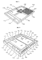
- FIG. 1 is an outside perspective view of an inner frame constituting a sifter frame of an embodiment of the present invention;
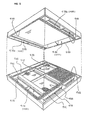
- FIG. 2 is an outside perspective view of an outer frame constituting the sifter frame of Fig.1;
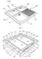
- FIG. 3 is an exploded view showing how the inner frame is fitted within the outer frame thereof;
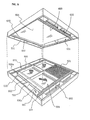
- FIG. 4 is an outside perspective view showing how the inner frame and the outer frame shown in the unfolded view of FIG. 3 are fitted with each other for assembly;
- FIG. 5 is an exploded view explaining a relationship of engagement when sifter frames of FIG. 4 each obtained by fitting the inner frame with the outer frame thereof,are stacked in an upward/downward direction;
- FIG. 6 is an outside perspective view showing an arrangement of an inner frame constituting a sifter frame of prior art;
- FIG. 7 is an outside perspective view showing an arrangement of an outer frame constituting the sifter frame of the prior art;
- FIG. 8 (a) is an exploded view showing
an inner frame and an outer frame constituting the sifter
frame of the prior art are fitted with each other for assembly
and FIG. 8 (b) is a longitudinal cross sectional view
showing engagement of the
frame member 502 of the inner frame within thepartition wall 604 of the outer frame - FIG. 9 is a view showing the relationship of engagement when the assembled sifter frames of the prior art are stacked in an upward/downward direction; and
- FIG. 10 is a view perspectively showing the interior of the main portion of the sifter frame of the prior art to show how a mixture of rough powder (powder particles to be treated),with fine powder.
-
- In FIG. 1 - FIG. 5, numeral 405 denotes an inner frame which is composed of, for example, square column wood frame members 452 - 455 constituting a rectangular four-sided frame, a
partition wall 458 for partitioning the inside of the rectangular four-side frame into a sifter net region 450 and a region for a roughpowder dropping port 459. Reinforcing wood bars 456, 457 are disposed in the sifter net region 450 in a cross shape, and asifter net 451 stretched over the upper surface of the sifter net region 450. Note, a crimp net is stretched in the vicinity of the lower side of thesifter net 451 in parallel therewith and a cleaner ( neither shown) is movably interposed between the nets to prevent the clogging of the net in a manner similar to the prior art arrangements of Fig. 6 to 10. - As apparent from FIG. 1 and FIG. 3, the
inner frame 405 of the embodiment has a feature that since each of the frame members 452 - 455 and thepartition wall 458 is composed of a square column member having the same height, the upper and lower surfaces of these frame members and the partition wall form rectangularly annular surfaces and the like which are flush with each other. Another feature of theinner frame 405 of the embodiment is that the threeframe members powder dropping port 459 provided in theinner frame 405 have upper and lower surfaces which can make an air-tight seal with a horizontal surface. Thus a roughpowder dropping port 469, which is provided within the outer frame into which theinner frame 405 is to be inserted and fitted, is air-tightly partitioned. - For the above purpose, the upper surfaces and lower surfaces of the inner frame of the embodiment are made flush with each other; that is, this arrangement is made so that when sifter frames are stacked to multi-stages, surfaces to be sealed are formed on the same plane. That is, to explain with respect to the above embodiment, in order to seal the engaging surfaces denoted by numeral 458a around the rough
powder dropping port 459, it is preferable to apply an intimate contact sheet such as non-woven fabric, felt or the like to the lower surface of the four sides thereof (or to the upper surface of the four sides of the outer frame) (refer to FIG. 3). An inclined surface similar to that of the prior art arrangements of Fig. 6 to 10 may be formed on the partition wall 458 (refer to numeral 502a of FIG. 6) to enable rough powder to easily drop into the roughpowder dropping port 459. - FIG. 2 shows the
outer frame 406 of the embodiment. An inner framefitting portion 460 formed as a recessed rectangular shape by a pair ofinner side walls outer side walls inner frame 405 which is inserted into and fitted within the outer frame is also formed to a rectangular shape. The inside of theouter frame 406 is partitioned to a fine powder receiving region provided with a receivingplate 467 and the roughpowder dropping port 469 by apartition wall 468. The roughpowder dropping port 469 and thepartition wall 468 are arranged such that the position and shape thereof coincide with those of the roughpowder dropping port 459 and thepartition wall 458 of theinner frame 405. - A pair of
outer side walls inner side walls outer side walls inner side walls blocks intermediate brackets powder dropping ports inner side walls outer side walls partition wall 468 to theouter side wall 462. - The receiving
plate 467 in the embodiment is composed of a rectangular stainless steel sheet fixed by screws to the lower surfaces of, for example, thepartition wall 468 and inner frame receiving stands 473, 474 disposed between a pair of theinner side walls 461 of the lower surfaces thereof. The inner frame receiving stands 473, 474 are composed of two wood bars each having the same height as that of thepartition wall 468. Further, lowerinner side walls plate 467 so that they constitute a pair with theinner side walls inner side walls frame receiving stand 474 is disposed in contact with theouter side wall 463 and another innerframe receiving stand 473 is disposed at an intermediate position between thepartition wall 468 and the innerframe receiving stand 474. Since they are disposed as described above, the receivingplate 467 provides a space for the fine powder receiving region for receiving fine powder (through) having passed through thesifter net 451 of theinner frame 405 inserted into and fitted within the inner frame fitting portion. As the shifter frame is vibrated, the fine powder is dropped into the finepowder dropping ports 465 from slit-shaped finepowder dropping ports 475 each formed between the lower surface of theinner side wall 461 and the receivingplate 467. Note, numeral 477 denotes brackets fixed to close gaps between theinner side wall 461 and the lowerinner side wall 476 at the both ends of the roughpowder dropping port 469. - The upper surface of the
partition wall 468 and the upper surfaces of the inner frame receiving stands 473, 474 in the inner frame fitting portion are located at such a depth that,when theinner frame 405 is placed on the above surfaces by being inserted into and fitted within the inner frame fitting portion, the upper surfaces of theinner side wall 461 and the outer side walls 462 - 464 are flush with the upper surface of theinner frame 405. - Note, as described with reference to FIG. 5, the lower
inner side wall 476 has a thickness for enabling thelower surface 476a thereof to be extended across the upper surfaces of theinner side wall 461 and the frame member 454 (or 455) of the inner frame of a sifter frame stacked to the lower stage. With this provision, when sifter frames are stacked, an intimate contact force can be applied to theinner frame 405 in a generally vertical direction and further a gap between theinner side wall 461 and the frame member 454 (or 455) through which rough powder may enter the fine powder region can be securely sealed by the lowerinner side wall 476 extending thereacross. Further, it is preferable that the lower portions of theouter side walls outer side wall 462 is composed of a frame member which is thicker than theouter side wall 463, and an additional depressing bracket is used so that the frame members 452, 453 of theinner frame 405 of a sifter frame stacked to the lower stage are depressed by theouter side walls outer frame 406 of the upper stage. - FIG. 3 shows how the
inner frame 405 arranged as described above is inserted into and fitted within the inner framefitting portion 460 of theouter frame 406 arranged as described above. That is, theinner frame 405 is inserted into and placed on thepartition wall 468 and the inner frame receiving stands 473, 474 in the inner framefitting portion 460 formed by the receivingplate 467, theinner side walls outer side walls outer frame 406. FIG. 4 shows the inside frame 5 assembled within the outer frame 6. - In this way, as shown in FIG. 4, a sifter frame is assembled such that the region of the rough
powder dropping port 469 is partitioned from the fine powder region (formed as the space between thesifter net 451 and the receiving plate 467) by thepartition walls powder dropping ports powder dropping ports 475,but are partitioned from the roughpowder dropping port 469 by theinner side wall 461, the lowerinner side wall 476 and thebrackets 477. - Then, as shown in FIG. 5, a plurality of the sifter frames each assembled as described above are stacked with the rough
powder dropping ports 469 thereof successively disposed alternately to arrange a group of the sifter frames. An annular seal surface 480 (shown by cross-hatching in the Figure) formed by applying the intimate contact sheet on the lower surface of the sifter frame of the upper stage in FIG. 5 comes into contact with a closedannular seal surface 481 formed on the upper surface of the sifter frame of the lower stage (shown by cross-hatching in the figure), so that these seal surfaces are caused to firmly come into contact with each other by biass pressure from the upper and lower side of the group of the sifter frames. With this arrangement, the roughpowder dropping ports 469 of the rough powder regions, which are partitioned from the other spaces by a plurality of the stacked sifter frames and directed generally vertically, are located at the alternate positions of the respective stages, Also, the space formed below thesifter net 451 and the receivingplate 467 of the upper stage sifter frame is partitioned and sealed from the finepowder dropping ports inner side wells powder dropping ports powder dropping ports 475 as described above. - When a group of the sifter frames each arranged as described above are stacked to multi-stages and rough powder is supplied onto the sifter net of the uppermost sifter frame while the sifter frames are caused to make a circular motion, the rough powder drops onto the
sifter net 451 of the next stage from the roughpowder dropping port 469 while moving on thesifter net 451, then moves on thesifter net 451 of the next stage to the roughpowder dropping port 469 located on the opposite side in the same way and further drops onto the sifter net of the next stage. Then, the rough powder is discharged to the outside of the system through the lowermost sifter frame while meandering with the successive repetition of the above operation. On the other hand, fine powder having passed through the sifter nets 451 of the respective stages drops onto a receivingplate 467, then drops into the finepowder dropping ports powder dropping ports 475 and is introduced to a fine powder collection path. - According to the sifter using the sifter frames arranged as described above, since the seal surfaces for partitioning and sealing the rough powder region from the fine powder region are formed as the annular seal surfaces located on the same plane, portions on which a pressure applying force does not act, which is found in prior art, do not exist anywhere, so that an intimate contact seal can be securely realized and a possibility of the mixture of rough powder with fine powder in the fine powder region can be securely prevented.
- When a test for sifting and separating flour was effected using the sifter having the arrangement of the invention described with reference to FIG. 1 - FIG. 5, it has been confirmed that the mixture of rough particles with fine powder can be completely prevented.
Claims (2)
- A sifter stage for being stacked with other similar stages to provide a multi-stage sifter for separating particulate material into sifted fine and non-sifted rough fractions, said sifter stage comprising:-characterised in that said outer frame (406) includes wall means (461--463) defining a rectangular recess for receiving said inner frame, and the upper surfaces of said wall means (461--463), and the upper peripheral surface of said inner rectangular frame element (452-455) together define an upwardly facing closed rectangular generally co-planar seal surface means (481), and selected lower surface regions of said outer frame (406) define a corresponding downwardly facing, closed rectangular generally co-planar seal surface means (480), whereby when stacked in use with a similar stage with the rough powder dropping posts alternately disposed, the downwardly facing seal surface means (480) is in sealing engagement with the upwardly facing seal surface means (481), and further in that said inner frame (405) includes a downwardly facing, closed rectangular seal surface means (458a) which surrounds said rough powder dropping port (459) and said outer frame (406) includes an upwardly facing, closed rectangular seal surface means (468) for sealingly co-operating with said downwardly facing seal surface means (458a).an outer frame (406),an inner frame (405) fitted within said outer frame (406),said inner frame (405) comprising a generally rectangular frame element (452-455) for supporting a perforate sieve surface (451),said outer frame (406) including a collection surface (467) for collecting sifted powder passing through said sieve surface (451) and discharging said collected powder into at least one fine powder dropping port (465) extending generally vertically, and means (461, 462, 468) defining a generally vertically extending rough powder dropping port (469) into which in use non-sifted powder is caused to pass on leaving said sieve surface (451),
- A sifter frame for a powder particle sifter, according to Claim 1, wherein an intimate contact seal sheet is applied to at least one of said seal surfaces (480,481).
Priority Applications (1)
| Application Number | Priority Date | Filing Date | Title |
|---|---|---|---|
| EP01115065A EP1145773A3 (en) | 1994-10-11 | 1994-11-11 | Sifter frame for powder particle sifter |
Applications Claiming Priority (6)
| Application Number | Priority Date | Filing Date | Title |
|---|---|---|---|
| JP24550594A JPH08108140A (en) | 1994-10-11 | 1994-10-11 | Sieve frame for multi-stage stacking type used for powder and grain sieving device |
| JP245505/94 | 1994-10-11 | ||
| JP24550594 | 1994-10-11 | ||
| JP26579294 | 1994-10-28 | ||
| JP26579294A JP3479565B2 (en) | 1994-10-28 | 1994-10-28 | Sieve frame for multi-stage lamination type used for granular material sieve device |
| JP265792/94 | 1994-10-28 |
Related Child Applications (1)
| Application Number | Title | Priority Date | Filing Date |
|---|---|---|---|
| EP01115065A Division EP1145773A3 (en) | 1994-10-11 | 1994-11-11 | Sifter frame for powder particle sifter |
Publications (2)
| Publication Number | Publication Date |
|---|---|
| EP0706836A1 EP0706836A1 (en) | 1996-04-17 |
| EP0706836B1 true EP0706836B1 (en) | 2002-02-06 |
Family
ID=26537265
Family Applications (2)
| Application Number | Title | Priority Date | Filing Date |
|---|---|---|---|
| EP01115065A Withdrawn EP1145773A3 (en) | 1994-10-11 | 1994-11-11 | Sifter frame for powder particle sifter |
| EP94308333A Expired - Lifetime EP0706836B1 (en) | 1994-10-11 | 1994-11-11 | Sifter frame for powder particle sifter |
Family Applications Before (1)
| Application Number | Title | Priority Date | Filing Date |
|---|---|---|---|
| EP01115065A Withdrawn EP1145773A3 (en) | 1994-10-11 | 1994-11-11 | Sifter frame for powder particle sifter |
Country Status (3)
| Country | Link |
|---|---|
| US (2) | US5598931A (en) |
| EP (2) | EP1145773A3 (en) |
| DE (1) | DE69429809T2 (en) |
Families Citing this family (16)
| Publication number | Priority date | Publication date | Assignee | Title |
|---|---|---|---|---|
| CN1072986C (en) | 1996-08-20 | 2001-10-17 | 比勒股份公司 | Plane sieve |
| DE19706601C1 (en) * | 1997-02-20 | 1998-11-12 | Buehler Ag | Screen frame for plansifter and process for its production |
| US6672460B2 (en) * | 1997-09-02 | 2004-01-06 | Southwestern Wire Cloth, Inc. | Vibrating screen assembly with integrated gasket and frame |
| US6439392B1 (en) * | 1997-09-02 | 2002-08-27 | Southwestern Wire Cloth, Inc. | Vibrating screen assembly with tubular frame |
| US7210582B2 (en) * | 2004-05-05 | 2007-05-01 | M-I L.L.C. | Screen and screen frame for improved screen to shaker placement, handling and retention |
| GB2419308A (en) * | 2004-10-14 | 2006-04-26 | Satake Eng Co Ltd | Sieve frame with labyrinth seal |
| US20070108107A1 (en) * | 2005-11-15 | 2007-05-17 | Morrow Deborah E | Disposable pre-tensioned sieve frame and method of making same |
| DE102006005967A1 (en) * | 2006-02-08 | 2007-08-09 | Bühler AG | scree |
| USD571168S1 (en) * | 2007-08-16 | 2008-06-17 | Dean Sais | Archaeological equipment sifter |
| US8679328B2 (en) * | 2012-04-10 | 2014-03-25 | Frank Hebert | Floor drain cover |
| WO2015126335A1 (en) * | 2014-02-18 | 2015-08-27 | Sedat Kunduraci | A modular sieving box |
| US10730076B2 (en) * | 2018-01-19 | 2020-08-04 | Ocrim S.P.A. | Interchangeable backwire/combined sieve and dynamic combined cleaner |
| CN111842096A (en) * | 2019-04-24 | 2020-10-30 | 布勒(无锡)商业有限公司 | Screen and screening equipment including the same |
| CN110280470B (en) * | 2019-05-22 | 2021-10-01 | 江苏谷泰粮食机械科技有限公司 | Grain sorting and screening structure for grain cleaning machine |
| CH720204A1 (en) * | 2022-11-07 | 2024-05-15 | Swisca Ag | Sieving device for plan sifters for fractionating grain mill products |
| CH720205A1 (en) * | 2022-11-07 | 2024-05-15 | Swisca Ag | Sieving device for plan sifters for fractionating grain mill products |
Family Cites Families (13)
| Publication number | Priority date | Publication date | Assignee | Title |
|---|---|---|---|---|
| US2068413A (en) * | 1934-11-26 | 1937-01-19 | Allan D Hunsicker | Sieve |
| US2181605A (en) * | 1936-10-21 | 1939-11-28 | William E Norvell | Separable sieve for bolters |
| FR892887A (en) * | 1943-03-26 | 1944-05-23 | Screening apparatus | |
| DE892887C (en) * | 1943-10-29 | 1953-10-12 | Sack Gmbh Maschf | Plate leveler |
| US2455383A (en) * | 1947-09-16 | 1948-12-07 | Richmond Mfg Company | Screen for gyratory sifters, screens, or bolting equipment |
| US2576794A (en) * | 1948-07-19 | 1951-11-27 | William R Jost | Demountable tray sieve |
| GB705389A (en) * | 1950-03-06 | 1954-03-10 | Miag Vertriebs Gmbh | Improvements in or relating to screening frames |
| AT169734B (en) * | 1950-08-18 | 1951-12-10 | Ernst Dipl Ing Fischer | Brush device for flour products |
| GB720437A (en) * | 1951-09-08 | 1954-12-22 | Miag Muehlenbau & Ind Gmbh | Improvements in or relating to slide frames for vibratory sieves |
| GB883054A (en) * | 1957-11-11 | 1961-11-22 | Simon Ltd Henry | Improvements in plansifters |
| US3565251A (en) * | 1968-12-30 | 1971-02-23 | Blaw Knox Co | Plastic internal screen |
| DE4101710A1 (en) * | 1991-01-22 | 1992-07-23 | Hein Lehmann Trenn Foerder | SCREEN AREA FOR A SCREENING MACHINE |
| CH685604A5 (en) * | 1992-02-29 | 1995-08-31 | Buehler Ag | Plansifter. |
-
1994
- 1994-11-07 US US08/335,578 patent/US5598931A/en not_active Expired - Fee Related
- 1994-11-11 EP EP01115065A patent/EP1145773A3/en not_active Withdrawn
- 1994-11-11 EP EP94308333A patent/EP0706836B1/en not_active Expired - Lifetime
- 1994-11-11 DE DE69429809T patent/DE69429809T2/en not_active Expired - Fee Related
-
1996
- 1996-06-12 US US08/662,065 patent/US5664686A/en not_active Expired - Fee Related
Also Published As
| Publication number | Publication date |
|---|---|
| EP1145773A2 (en) | 2001-10-17 |
| DE69429809T2 (en) | 2002-09-12 |
| DE69429809D1 (en) | 2002-03-21 |
| EP0706836A1 (en) | 1996-04-17 |
| US5664686A (en) | 1997-09-09 |
| EP1145773A3 (en) | 2001-10-24 |
| US5598931A (en) | 1997-02-04 |
Similar Documents
| Publication | Publication Date | Title |
|---|---|---|
| JP3316032B2 (en) | Sieve frame for granular material sieving machine | |
| EP1145773A2 (en) | Sifter frame for powder particle sifter | |
| US6202857B1 (en) | Frame for flat sifter and process for producing the same | |
| CN101056717B (en) | Devices for separating granular materials | |
| CA2469352A1 (en) | A screen assembly for a vibratory separator | |
| US4863588A (en) | Riffle bars | |
| JP3479565B2 (en) | Sieve frame for multi-stage lamination type used for granular material sieve device | |
| JP5229494B2 (en) | Purifier | |
| JP4176226B2 (en) | Method for screening powder particles | |
| KR20220047723A (en) | Sieve frame and sieving device including same | |
| JP2001300426A (en) | Granular sieving device with multi-tiered sieve frame unit | |
| CN120152792A (en) | Screening device with flat screen for grading grain milling products | |
| JP2000189896A (en) | Sieve frame for multi-stage lamination type used in granular material sieve device | |
| US2865506A (en) | Separators for pulverulent materials | |
| JPH08108140A (en) | Sieve frame for multi-stage stacking type used for powder and grain sieving device | |
| SU1286301A1 (en) | Sifter for sorting loose materials | |
| EP1384526A1 (en) | Method,screen and plansifter for sifting products having different particle sizes | |
| WO2020160631A1 (en) | Modular mesh for cubic and lamellar sorting in vibrating screens and independent vibrating systems | |
| JP3612825B2 (en) | Sieve screen frame | |
| CN219850638U (en) | Length-limited reciprocating resonance screen | |
| GB2276572A (en) | Screen frame assembly with frame-bonded screen cloth and removable ball tray | |
| CN101378848A (en) | Sieve | |
| JPH04131466U (en) | Composite vibrating sieve | |
| WO2026077933A1 (en) | Seal for a sieve frame | |
| AU2023303830A1 (en) | Plansifter |
Legal Events
| Date | Code | Title | Description |
|---|---|---|---|
| PUAI | Public reference made under article 153(3) epc to a published international application that has entered the european phase |
Free format text: ORIGINAL CODE: 0009012 |
|
| AK | Designated contracting states |
Kind code of ref document: A1 Designated state(s): CH DE GB LI |
|
| 17P | Request for examination filed |
Effective date: 19960723 |
|
| 17Q | First examination report despatched |
Effective date: 19981120 |
|
| GRAG | Despatch of communication of intention to grant |
Free format text: ORIGINAL CODE: EPIDOS AGRA |
|
| GRAG | Despatch of communication of intention to grant |
Free format text: ORIGINAL CODE: EPIDOS AGRA |
|
| GRAH | Despatch of communication of intention to grant a patent |
Free format text: ORIGINAL CODE: EPIDOS IGRA |
|
| GRAH | Despatch of communication of intention to grant a patent |
Free format text: ORIGINAL CODE: EPIDOS IGRA |
|
| GRAA | (expected) grant |
Free format text: ORIGINAL CODE: 0009210 |
|
| REG | Reference to a national code |
Ref country code: GB Ref legal event code: IF02 |
|
| RAP1 | Party data changed (applicant data changed or rights of an application transferred) |
Owner name: NISSHIN SEIFUN GROUP INC. |
|
| AK | Designated contracting states |
Kind code of ref document: B1 Designated state(s): CH DE GB LI |
|
| REG | Reference to a national code |
Ref country code: CH Ref legal event code: EP |
|
| RAP2 | Party data changed (patent owner data changed or rights of a patent transferred) |
Owner name: NISSHIN FLOUR MILLING INC. |
|
| REF | Corresponds to: |
Ref document number: 69429809 Country of ref document: DE Date of ref document: 20020321 |
|
| REG | Reference to a national code |
Ref country code: CH Ref legal event code: NV Representative=s name: BOVARD AG PATENTANWAELTE |
|
| PLBE | No opposition filed within time limit |
Free format text: ORIGINAL CODE: 0009261 |
|
| STAA | Information on the status of an ep patent application or granted ep patent |
Free format text: STATUS: NO OPPOSITION FILED WITHIN TIME LIMIT |
|
| 26N | No opposition filed |
Effective date: 20021107 |
|
| PGFP | Annual fee paid to national office [announced via postgrant information from national office to epo] |
Ref country code: DE Payment date: 20051103 Year of fee payment: 12 |
|
| PGFP | Annual fee paid to national office [announced via postgrant information from national office to epo] |
Ref country code: GB Payment date: 20051109 Year of fee payment: 12 |
|
| PGFP | Annual fee paid to national office [announced via postgrant information from national office to epo] |
Ref country code: CH Payment date: 20051115 Year of fee payment: 12 |
|
| PG25 | Lapsed in a contracting state [announced via postgrant information from national office to epo] |
Ref country code: LI Free format text: LAPSE BECAUSE OF NON-PAYMENT OF DUE FEES Effective date: 20061130 Ref country code: CH Free format text: LAPSE BECAUSE OF NON-PAYMENT OF DUE FEES Effective date: 20061130 |
|
| PG25 | Lapsed in a contracting state [announced via postgrant information from national office to epo] |
Ref country code: DE Free format text: LAPSE BECAUSE OF NON-PAYMENT OF DUE FEES Effective date: 20070601 |
|
| REG | Reference to a national code |
Ref country code: CH Ref legal event code: PL |
|
| GBPC | Gb: european patent ceased through non-payment of renewal fee |
Effective date: 20061111 |
|
| PG25 | Lapsed in a contracting state [announced via postgrant information from national office to epo] |
Ref country code: GB Free format text: LAPSE BECAUSE OF NON-PAYMENT OF DUE FEES Effective date: 20061111 |