JP3612825B2 - Sieve screen frame - Google Patents
Sieve screen frame Download PDFInfo
- Publication number
- JP3612825B2 JP3612825B2 JP30993495A JP30993495A JP3612825B2 JP 3612825 B2 JP3612825 B2 JP 3612825B2 JP 30993495 A JP30993495 A JP 30993495A JP 30993495 A JP30993495 A JP 30993495A JP 3612825 B2 JP3612825 B2 JP 3612825B2
- Authority
- JP
- Japan
- Prior art keywords
- frame
- bottom plate
- fine powder
- opening
- sieve
- Prior art date
- Legal status (The legal status is an assumption and is not a legal conclusion. Google has not performed a legal analysis and makes no representation as to the accuracy of the status listed.)
- Expired - Lifetime
Links
Images


Description
【0001】
【産業上の利用分野】
本発明は、小麦粉等の粉粒体を粒度により選別するための篩機の篩網枠に関する。
【0002】
【従来の技術】
粉粒体、特に小麦粉を粒度により選別するための篩機としては、篩網枠を多数積み重ね、これを天井から吊すか、又は、床から支持棒等で支え、バランスウエイトを備えた偏心軸と駆動軸とからなる駆動手段により水平面で円運動させる方式の、いわゆるプランシフター、スクウエアーシフター又はジュニアシフターが広く用いられている。
【0003】
上記篩機の篩網枠は、小麦粉を網上分(粗粉)と網下分(微粉)に分離する内枠と、この内枠を嵌合して、内枠からの粉を受けて次段の篩網枠へ供給する外枠とから構成されており、このような構成の篩網枠を図4及び図5を参照して説明する。
【0004】
図4は従来の篩網枠の内枠を示すものであり、内枠51は四角形状の枠体を構成する木製の枠辺53と、その枠体の内側に十字に架設した補強棒体54との上に、篩網55を張った構成をなしている。
【0005】
図5に示す従来の外枠52は、前記内枠51を嵌合させる内側壁56と、この内側壁56の外側に設けられて微粉用開口57形成する一対の外側壁58と、他対の対向辺の外側壁59と、内枠の篩網を通過した微粉を前記微粉用開口57に誘導する底板60とから構成される。そして、該底板60は、例えばステンレス製であって、前記内側壁56付近に、底板60の上面から皿ビス61で止められている。
【0006】
しかしながら、上記の篩網枠においては、底板60を上面から皿ビス61により止めているため(図6参照)、底板60の見栄えが悪く、しかも、長期使用していると皿ビス61の頭部61aが浮いた状態となる欠点があった。このため、皿ビス60付近に微粉が付着したり、また、底板60上を遊動して微粉を開口57に落下させるクリーナー自体が、皿ビス61の頭部61a及び底板60の端縁と接触して欠損することがあり、この破片が微粉の中に混入する危険性があった。
【0007】
ところで、特開平6ー320111号公報の実施例中には、「本例における上記の受板63は、平行な3本の木製棒体64の下面にステンレス製の矩形板をビス止めして構成され、…」と記載されている。このような篩網枠においては、受板63を延設して、木製棒体64の側面を被覆するように折曲して該木製棒体64下面でビス止めしているため、篩網枠の製造工程で加工に要する手間が掛かるといった欠点があった。
【0008】
本発明は上記問題点にかんがみ、簡単な構成で、かつ、底板に微粉が付着することがなく、また、底板と内枠との間に介挿したクリーナーの耐用年数を向上させ、更には、クリーナーの破片が微粉の中に混入する危険のない篩機の篩網枠を提供することを技術的課題とする。
【0009】
【課題を解決するための手段】
本発明は上記課題を解決するため、篩網を張った四角形状の内枠と、該内枠が嵌合する外枠との対からなり、該外枠は、前記内枠の篩網を通過した微粉を受ける底板と、該底板上の微粉を枠外へ排出するため対向状に設けた一対の微粉用開口と、前記篩網上の粗粉を枠外へ排出する粗粉用開口とを設けた篩機の篩網枠において、前記底板は、前記底板は、前記微粉用開口に沿って延びる支持部材の上面から微粉用開口側側面に密着して下方に折り曲げられるとともに、前記微粉用開口に横架した複数個のクリーナー落下防止梁により底板を支持部材に繋止する、という技術的手段を講じた。
【0010】
【作用及び効果】
底板は、微粉用開口に沿って延びる支持部材の上面から微粉用開口側側面に密着して下方に折り曲げられるとともに、微粉用開口に横架した複数個のクリーナー落下防止梁により底板を支持部材に繋止しているので、底板の上面には皿ネジが無く、しかも、底板の端縁は滑らかであるので、微粉が底板の皿ネジ付近に付着することがなく、また、クリーナー自体の欠損がなくなり、クリーナーの破片が微粉の中に混入する危険がなくなった。また、クリーナー落下防止梁を設けているので、クリーナーが微粉用開口に移動しても落下することがない。
【0011】
【実施例】
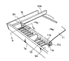
以下、本発明の好適な実施例を図1を参照しながら説明する。
【0012】
符号1は、上面に篩網2が張設された内枠で、木製の枠体3a,3b,3c,3dにより四方を囲まれ、枠体3aは、篩網2の上側を流れる粗粉が内枠1外に容易に流出するように、下方への緩傾斜が設けられている。内枠1には、補強体4が設けられており、該補強体4の下面には篩網2よりも目の粗い金網5が張設されている。そして、前記篩網2と金網5との間には例えばコットンクリーナー(図示せず)等を介挿させて篩網2の目詰まりを防止するように設けている。
【0013】
外枠6は、四方を外側壁7により囲まれ、4つの外側壁のうち、対向する1対の外側壁7a,7cの内方には、各々内側壁8a,8bが前記外側壁7a,7cと平行となるように配設されており、外側壁7aと内側壁8aとの間で微粉用開口9aを、外側壁7cと内側壁8bとの間で微粉用開口9bをそれぞれ形成する。
【0014】
符号10は、外側壁7に固設され、その上面が内枠1の枠体3下面と係合するとともに、その下面に篩網2からの微粉を受けて微粉用開口9a,9bへ移動させるための底板11が固着した支持部材である。そして、支持部材10aと外側壁7dとの間には、篩網2上を移動する粗粉を外枠6外へ排出するための粗粉用開口12が形成されている。そして、前記微粉用開口9a,9bには、クリーナー落下防止梁13を複数個横架してあるので、底板11と金網5との間に介挿する例えば樹脂製のクリーナー(図示せず)の微粉用開口9a,9bへの落下が防止される。
【0015】
次に、前記底板11の外枠6への取付方法について図2及び図3を参照して説明する。
【0016】
図2は、底板11の取付状態を説明するため、微粉用開口9aを拡大した斜視図であり、図3は図2のAーA断面図である。図3において、前記内側壁8aの直下には、前記微粉用開口9aに沿って支持部材10cが設けられる。そして、前記底板11は、支持部材10cから外側壁7a側に向けて延設するとともに、その延設部11aを支持部材10cの上面から微粉用開口9a側側面に密着して下方に折り曲げ、複数個のクリーナー落下防止梁13により底板11を支持部材10cに繋止する。該複数個のクリーナー落下防止梁13は、前記支持部材10cと外側壁7aとの間に横架されており、前記底板11の一辺に穿設した穴11bに挿嵌する。そして、本実施例では省略してあるが、底板11の対向した他辺も同様にして取り付けるとよい。
【0017】
以上のように構成した篩網枠の作用を以下説明する。
【0018】
底板11に微粉が付着するのを防止するため、底板11と内枠1との間にクリーナー(図示せず)を介挿して、内枠1を外枠6に嵌合する。そして、篩網2上に粉粒体を供給すると、篩網2を通過した微粉は底板11で受けられ、クリーナーが遊動することにより微粉用開口9に落下させ、外枠6外へ排出させる。このとき、底板11の上面には皿ネジが無く、しかも、底板11の端縁は滑らかであるので、微粉が底板11に付着することがなく、また、クリーナー自体の欠損がなくなり、クリーナーの破片が微粉の中に混入する危険がなくなった。
【0019】
そして、篩網2を通過しない粗粉は篩網2上を移動し、枠体3a上を通って粗粉用開口12から外枠6外へ排出される。
【図面の簡単な説明】
【図1】内枠と外枠とを嵌合させた状態を示す展開図である。
【図2】底板の取付状態を説明するため、微粉用開口部を拡大した斜視図である。
【図3】図2のA−A断面図である。
【図4】従来の篩網枠の内枠を示す斜視図である。
【図5】従来の篩網枠の外枠を示す斜視図である。
【図6】図5のB−B断面図である。
【符号の説明】
1 内枠
2 篩網
3 枠体
4 補強体
5 金網
6 外枠
7 外側壁
8 内側壁
9 微粉用開口
10 支持部材
11 底板
12 粗粉用開口
13 クリーナー落下防止梁[0001]
[Industrial application fields]
The present invention relates to a sieving mesh frame of a sieving machine for sorting powder particles such as wheat flour according to particle size.
[0002]
[Prior art]
As a sieving machine for sorting powders, especially wheat flour, according to particle size, a large number of sieve mesh frames are stacked and suspended from the ceiling, or supported by a support bar etc. from the floor, and an eccentric shaft with a balance weight A so-called plan shifter, square shifter, or junior shifter that is circularly moved on a horizontal plane by a driving means including a driving shaft is widely used.
[0003]
The sieving mesh frame of the sieving machine includes an inner frame that separates wheat flour into a net content (coarse powder) and a net content (fine powder), and this inner frame is fitted to receive the powder from the inner frame. It is comprised from the outer frame supplied to the sieve mesh frame of a stage, and the sieve mesh frame of such a structure is demonstrated with reference to FIG.4 and FIG.5.
[0004]
FIG. 4 shows an inner frame of a conventional sieve mesh frame. An
[0005]
A conventional
[0006]
However, in the above sieve mesh frame, since the
[0007]
By the way, in the embodiment of Japanese Patent Laid-Open No. 6-320111, “the receiving plate 63 in this example is configured by screwing a stainless steel rectangular plate on the lower surface of three parallel wooden rods 64. And ... ". In such a screen mesh frame, the receiving plate 63 is extended, bent so as to cover the side surface of the wooden rod body 64, and screwed at the lower surface of the wooden rod body 64. There is a drawback that it takes time and effort to process in the manufacturing process.
[0008]
In view of the above problems, the present invention has a simple configuration, and fine powder does not adhere to the bottom plate.In addition, the service life of the cleaner interposed between the bottom plate and the inner frame is improved. It is a technical object to provide a sieve screen frame of a sieve machine that does not risk the contamination of cleaner fragments into fine powder.
[0009]
[Means for Solving the Problems]
In order to solve the above problems, the present invention comprises a pair of a rectangular inner frame stretched with a screen and an outer frame to which the inner frame fits, and the outer frame passes through the screen of the inner frame. A bottom plate for receiving the fine powder, a pair of fine powder openings provided in an opposing manner for discharging the fine powder on the bottom plate to the outside of the frame, and a coarse powder opening for discharging the coarse powder on the sieve screen to the outside of the frame in sieve screen frame sieve machine, the bottom plate, the bottom plate is bent downward in close contact with the fine opening side surface from the upper surface of the support member extending I along with the fine opening Rutotomoni, the pulverized opening Technical measures were taken to secure the bottom plate to the support member by means of a plurality of cleaner fall-preventing beams laid horizontally.
[0010]
[Action and effect]
The bottom plate, with bent downward in close contact with the upper surface of the support member extending I along the fine opening in the fine opening side surface, the support member bottom plate by a plurality of cleaner fall prevention Beams laterally placed micronized opening since the sealed joint to, no countersunk screws to the top surface of the bottom plate, moreover, since the edge of the bottom plate is smooth, without fine powder adheres to the vicinity of the countersunk screw of the bottom plate, also deficient cleaner itself There is no longer any danger of cleaner fragments entering the fine powder. Moreover, since the cleaner fall prevention beam is provided, even if the cleaner moves to the fine powder opening, it does not fall.
[0011]
【Example】
Hereinafter , a preferred embodiment of the present invention will be described with reference to FIG.
[0012]
[0013]
The
[0014]
Reference numeral 10 is fixed to the outer wall 7, and its upper surface engages with the lower surface of the frame 3 of the
[0015]
Next, a method for attaching the
[0016]
FIG. 2 is an enlarged perspective view of the fine powder opening 9a for explaining the mounting state of the
[0017]
The operation of the screen mesh frame configured as described above will be described below.
[0018]
In order to prevent fine powder from adhering to the
[0019]
The coarse powder that does not pass through the sieve mesh 2 moves on the sieve mesh 2, passes through the frame 3 a, and is discharged from the
[Brief description of the drawings]
FIG. 1 is a development view showing a state in which an inner frame and an outer frame are fitted together.
FIG. 2 is an enlarged perspective view of a fine powder opening in order to explain a mounting state of a bottom plate.
3 is a cross-sectional view taken along the line AA in FIG.
FIG. 4 is a perspective view showing an inner frame of a conventional sieve mesh frame.
FIG. 5 is a perspective view showing an outer frame of a conventional sieve mesh frame.
6 is a cross-sectional view taken along the line BB in FIG.
[Explanation of symbols]
DESCRIPTION OF
Claims (1)
Priority Applications (1)
| Application Number | Priority Date | Filing Date | Title |
|---|---|---|---|
| JP30993495A JP3612825B2 (en) | 1995-11-02 | 1995-11-02 | Sieve screen frame |
Applications Claiming Priority (1)
| Application Number | Priority Date | Filing Date | Title |
|---|---|---|---|
| JP30993495A JP3612825B2 (en) | 1995-11-02 | 1995-11-02 | Sieve screen frame |
Publications (2)
| Publication Number | Publication Date |
|---|---|
| JPH09122592A JPH09122592A (en) | 1997-05-13 |
| JP3612825B2 true JP3612825B2 (en) | 2005-01-19 |
Family
ID=17999114
Family Applications (1)
| Application Number | Title | Priority Date | Filing Date |
|---|---|---|---|
| JP30993495A Expired - Lifetime JP3612825B2 (en) | 1995-11-02 | 1995-11-02 | Sieve screen frame |
Country Status (1)
| Country | Link |
|---|---|
| JP (1) | JP3612825B2 (en) |
-
1995
- 1995-11-02 JP JP30993495A patent/JP3612825B2/en not_active Expired - Lifetime
Also Published As
| Publication number | Publication date |
|---|---|
| JPH09122592A (en) | 1997-05-13 |
Similar Documents
| Publication | Publication Date | Title |
|---|---|---|
| US8522981B2 (en) | Screening machine and associated screen panel | |
| US5221008A (en) | Vibratory screening machine and non-clogging wear-reducing screen assembly therefor | |
| US3565251A (en) | Plastic internal screen | |
| SK281264B6 (en) | Device for flat sieving machines | |
| US20100018910A1 (en) | Screening machine screen panel | |
| US4288320A (en) | Vibrating screen with screen deck unclogging mechanism | |
| JP3316032B2 (en) | Sieve frame for granular material sieving machine | |
| CA2261788C (en) | Screen for vibrating material sorting apparatus | |
| US3232431A (en) | Stepped screens | |
| EP1145773A2 (en) | Sifter frame for powder particle sifter | |
| JP3612825B2 (en) | Sieve screen frame | |
| US2497902A (en) | Screen clearer for gyratory sifters | |
| CN206083142U (en) | Novel two proportion grain preparators of double entry | |
| CN109865660A (en) | A kind of vibrating screen | |
| US3478406A (en) | Screening separator | |
| JP3479565B2 (en) | Sieve frame for multi-stage lamination type used for granular material sieve device | |
| CN200988032Y (en) | Micro fine grding sieve | |
| JPH0938579A (en) | Screen frame of screening machine | |
| GB2276572A (en) | Screen frame assembly with frame-bonded screen cloth and removable ball tray | |
| CN2461667Y (en) | Sizing shaker | |
| GB2073618A (en) | Vibratory screening panels | |
| JP2911818B2 (en) | Gravel sorter | |
| JP2003340373A (en) | Vibration sieving apparatus | |
| CN217569680U (en) | Medicinal material fine screening device | |
| JP2000189896A (en) | Multistage lamination type sieve frame for granule sieving apparatus |
Legal Events
| Date | Code | Title | Description |
|---|---|---|---|
| A977 | Report on retrieval |
Free format text: JAPANESE INTERMEDIATE CODE: A971007 Effective date: 20040531 |
|
| A131 | Notification of reasons for refusal |
Free format text: JAPANESE INTERMEDIATE CODE: A131 Effective date: 20040902 |
|
| A521 | Written amendment |
Free format text: JAPANESE INTERMEDIATE CODE: A523 Effective date: 20040906 |
|
| TRDD | Decision of grant or rejection written | ||
| A01 | Written decision to grant a patent or to grant a registration (utility model) |
Free format text: JAPANESE INTERMEDIATE CODE: A01 Effective date: 20041005 |
|
| A61 | First payment of annual fees (during grant procedure) |
Free format text: JAPANESE INTERMEDIATE CODE: A61 Effective date: 20041018 |
|
| R150 | Certificate of patent or registration of utility model |
Free format text: JAPANESE INTERMEDIATE CODE: R150 |
|
| FPAY | Renewal fee payment (event date is renewal date of database) |
Free format text: PAYMENT UNTIL: 20071105 Year of fee payment: 3 |
|
| FPAY | Renewal fee payment (event date is renewal date of database) |
Free format text: PAYMENT UNTIL: 20081105 Year of fee payment: 4 |
|
| FPAY | Renewal fee payment (event date is renewal date of database) |
Free format text: PAYMENT UNTIL: 20091105 Year of fee payment: 5 |
|
| FPAY | Renewal fee payment (event date is renewal date of database) |
Free format text: PAYMENT UNTIL: 20091105 Year of fee payment: 5 |
|
| FPAY | Renewal fee payment (event date is renewal date of database) |
Free format text: PAYMENT UNTIL: 20091105 Year of fee payment: 5 |
|
| FPAY | Renewal fee payment (event date is renewal date of database) |
Free format text: PAYMENT UNTIL: 20101105 Year of fee payment: 6 |
|
| FPAY | Renewal fee payment (event date is renewal date of database) |
Free format text: PAYMENT UNTIL: 20101105 Year of fee payment: 6 |
|
| FPAY | Renewal fee payment (event date is renewal date of database) |
Free format text: PAYMENT UNTIL: 20111105 Year of fee payment: 7 |
|
| FPAY | Renewal fee payment (event date is renewal date of database) |
Free format text: PAYMENT UNTIL: 20111105 Year of fee payment: 7 |
|
| FPAY | Renewal fee payment (event date is renewal date of database) |
Free format text: PAYMENT UNTIL: 20121105 Year of fee payment: 8 |
|
| FPAY | Renewal fee payment (event date is renewal date of database) |
Free format text: PAYMENT UNTIL: 20121105 Year of fee payment: 8 |
|
| FPAY | Renewal fee payment (event date is renewal date of database) |
Free format text: PAYMENT UNTIL: 20121105 Year of fee payment: 8 |
|
| FPAY | Renewal fee payment (event date is renewal date of database) |
Free format text: PAYMENT UNTIL: 20121105 Year of fee payment: 8 |
|
| FPAY | Renewal fee payment (event date is renewal date of database) |
Free format text: PAYMENT UNTIL: 20121105 Year of fee payment: 8 |
|
| FPAY | Renewal fee payment (event date is renewal date of database) |
Free format text: PAYMENT UNTIL: 20131105 Year of fee payment: 9 |
|
| R250 | Receipt of annual fees |
Free format text: JAPANESE INTERMEDIATE CODE: R250 |
|
| EXPY | Cancellation because of completion of term |