EP0706776B1 - Organism information measuring apparatus and pulse-wave measuring apparatus - Google Patents
Organism information measuring apparatus and pulse-wave measuring apparatus Download PDFInfo
- Publication number
- EP0706776B1 EP0706776B1 EP95306336A EP95306336A EP0706776B1 EP 0706776 B1 EP0706776 B1 EP 0706776B1 EP 95306336 A EP95306336 A EP 95306336A EP 95306336 A EP95306336 A EP 95306336A EP 0706776 B1 EP0706776 B1 EP 0706776B1
- Authority
- EP
- European Patent Office
- Prior art keywords
- light
- measuring apparatus
- pulse
- light emitting
- organism
- Prior art date
- Legal status (The legal status is an assumption and is not a legal conclusion. Google has not performed a legal analysis and makes no representation as to the accuracy of the status listed.)
- Expired - Lifetime
Links
- 238000001514 detection method Methods 0.000 claims description 51
- 238000000034 method Methods 0.000 claims description 9
- 230000001678 irradiating effect Effects 0.000 claims description 6
- 210000000707 wrist Anatomy 0.000 claims description 5
- 229910052757 nitrogen Inorganic materials 0.000 claims description 4
- IJGRMHOSHXDMSA-UHFFFAOYSA-N nitrogen Substances N#N IJGRMHOSHXDMSA-UHFFFAOYSA-N 0.000 claims description 4
- 229910052698 phosphorus Inorganic materials 0.000 claims description 4
- 239000011574 phosphorus Substances 0.000 claims description 4
- 230000008054 signal transmission Effects 0.000 claims description 3
- 210000003811 finger Anatomy 0.000 description 83
- 230000003287 optical effect Effects 0.000 description 23
- 239000008280 blood Substances 0.000 description 20
- 210000004369 blood Anatomy 0.000 description 20
- 108010054147 Hemoglobins Proteins 0.000 description 19
- 102000001554 Hemoglobins Human genes 0.000 description 19
- 230000031700 light absorption Effects 0.000 description 18
- 210000004204 blood vessel Anatomy 0.000 description 16
- 230000000052 comparative effect Effects 0.000 description 14
- 230000035945 sensitivity Effects 0.000 description 14
- 230000008859 change Effects 0.000 description 12
- 238000005259 measurement Methods 0.000 description 10
- 238000012545 processing Methods 0.000 description 10
- 230000005540 biological transmission Effects 0.000 description 8
- 230000001351 cycling effect Effects 0.000 description 6
- 239000011521 glass Substances 0.000 description 6
- 210000003813 thumb Anatomy 0.000 description 5
- 238000004458 analytical method Methods 0.000 description 4
- 238000000295 emission spectrum Methods 0.000 description 4
- 239000004973 liquid crystal related substance Substances 0.000 description 4
- QVGXLLKOCUKJST-UHFFFAOYSA-N atomic oxygen Chemical compound [O] QVGXLLKOCUKJST-UHFFFAOYSA-N 0.000 description 3
- 210000005224 forefinger Anatomy 0.000 description 3
- 229910052760 oxygen Inorganic materials 0.000 description 3
- 239000001301 oxygen Substances 0.000 description 3
- 238000003860 storage Methods 0.000 description 3
- 238000002834 transmittance Methods 0.000 description 3
- XUIMIQQOPSSXEZ-UHFFFAOYSA-N Silicon Chemical compound [Si] XUIMIQQOPSSXEZ-UHFFFAOYSA-N 0.000 description 2
- 230000008901 benefit Effects 0.000 description 2
- 238000004364 calculation method Methods 0.000 description 2
- 238000010586 diagram Methods 0.000 description 2
- 238000009826 distribution Methods 0.000 description 2
- 230000000694 effects Effects 0.000 description 2
- 238000011156 evaluation Methods 0.000 description 2
- 238000000605 extraction Methods 0.000 description 2
- 238000011835 investigation Methods 0.000 description 2
- 210000004932 little finger Anatomy 0.000 description 2
- 239000011347 resin Substances 0.000 description 2
- 229920005989 resin Polymers 0.000 description 2
- 229910052710 silicon Inorganic materials 0.000 description 2
- 239000010703 silicon Substances 0.000 description 2
- 230000036555 skin type Effects 0.000 description 2
- XLYOFNOQVPJJNP-UHFFFAOYSA-N water Substances O XLYOFNOQVPJJNP-UHFFFAOYSA-N 0.000 description 2
- 230000004308 accommodation Effects 0.000 description 1
- 230000036760 body temperature Effects 0.000 description 1
- 239000003990 capacitor Substances 0.000 description 1
- 238000006243 chemical reaction Methods 0.000 description 1
- 238000010276 construction Methods 0.000 description 1
- 238000007796 conventional method Methods 0.000 description 1
- 239000000284 extract Substances 0.000 description 1
- 239000000835 fiber Substances 0.000 description 1
- 108010036302 hemoglobin AS Proteins 0.000 description 1
- 230000006872 improvement Effects 0.000 description 1
- 238000004519 manufacturing process Methods 0.000 description 1
- 239000000463 material Substances 0.000 description 1
- 230000000414 obstructive effect Effects 0.000 description 1
- 230000037368 penetrate the skin Effects 0.000 description 1
- 230000005855 radiation Effects 0.000 description 1
- 230000009467 reduction Effects 0.000 description 1
- 238000009877 rendering Methods 0.000 description 1
- 230000004044 response Effects 0.000 description 1
- 238000000926 separation method Methods 0.000 description 1
Images


Classifications
-
- A—HUMAN NECESSITIES
- A61—MEDICAL OR VETERINARY SCIENCE; HYGIENE
- A61B—DIAGNOSIS; SURGERY; IDENTIFICATION
- A61B5/00—Measuring for diagnostic purposes; Identification of persons
- A61B5/22—Ergometry; Measuring muscular strength or the force of a muscular blow
- A61B5/221—Ergometry, e.g. by using bicycle type apparatus
- A61B5/222—Ergometry, e.g. by using bicycle type apparatus combined with detection or measurement of physiological parameters, e.g. heart rate
-
- A—HUMAN NECESSITIES
- A61—MEDICAL OR VETERINARY SCIENCE; HYGIENE
- A61B—DIAGNOSIS; SURGERY; IDENTIFICATION
- A61B5/00—Measuring for diagnostic purposes; Identification of persons
- A61B5/02—Detecting, measuring or recording pulse, heart rate, blood pressure or blood flow; Combined pulse/heart-rate/blood pressure determination; Evaluating a cardiovascular condition not otherwise provided for, e.g. using combinations of techniques provided for in this group with electrocardiography or electroauscultation; Heart catheters for measuring blood pressure
- A61B5/024—Detecting, measuring or recording pulse rate or heart rate
- A61B5/02416—Detecting, measuring or recording pulse rate or heart rate using photoplethysmograph signals, e.g. generated by infrared radiation
-
- A—HUMAN NECESSITIES
- A61—MEDICAL OR VETERINARY SCIENCE; HYGIENE
- A61B—DIAGNOSIS; SURGERY; IDENTIFICATION
- A61B5/00—Measuring for diagnostic purposes; Identification of persons
- A61B5/68—Arrangements of detecting, measuring or recording means, e.g. sensors, in relation to patient
- A61B5/6801—Arrangements of detecting, measuring or recording means, e.g. sensors, in relation to patient specially adapted to be attached to or worn on the body surface
- A61B5/6802—Sensor mounted on worn items
- A61B5/681—Wristwatch-type devices
-
- A—HUMAN NECESSITIES
- A61—MEDICAL OR VETERINARY SCIENCE; HYGIENE
- A61B—DIAGNOSIS; SURGERY; IDENTIFICATION
- A61B5/00—Measuring for diagnostic purposes; Identification of persons
- A61B5/68—Arrangements of detecting, measuring or recording means, e.g. sensors, in relation to patient
- A61B5/6801—Arrangements of detecting, measuring or recording means, e.g. sensors, in relation to patient specially adapted to be attached to or worn on the body surface
- A61B5/6813—Specially adapted to be attached to a specific body part
- A61B5/6824—Arm or wrist
-
- A—HUMAN NECESSITIES
- A61—MEDICAL OR VETERINARY SCIENCE; HYGIENE
- A61B—DIAGNOSIS; SURGERY; IDENTIFICATION
- A61B5/00—Measuring for diagnostic purposes; Identification of persons
- A61B5/68—Arrangements of detecting, measuring or recording means, e.g. sensors, in relation to patient
- A61B5/6801—Arrangements of detecting, measuring or recording means, e.g. sensors, in relation to patient specially adapted to be attached to or worn on the body surface
- A61B5/6813—Specially adapted to be attached to a specific body part
- A61B5/6825—Hand
- A61B5/6826—Finger
Definitions
- the present invention relates to an organism information measuring apparatus, such as a pulse-wave measuring apparatus.
- the apparatus may display information about the pulse wave, such as the pulse rate. More particularly, but not exclusively, the present invention relates to an apparatus that irradiates an organism such as a blood vessel with light and detects light reflected by the organism to measure information about the organism, such as the pulse waves.
- the present invention also relates to a pulse-wave measuring apparatus which is worn on the user's arm, and which is capable of measuring information about the organism during an exercise, such as jogging, running or cycling.
- Devices for detecting information (such as pulse waves) from an organism include electronic apparatus of a type that optically detects changes in the quantity of blood to display information about an organism in accordance with results of the detection.
- a light emitting device such as an LED (Light Emitting Diode)
- irradiates the fingertip or the like with light and light reflected by the organism (the blood vessel) is received by a light receiving device, such as a phototransistor, so that changes in the quantity of blood passing through the blood vessel occurring due to the pulse waves of the blood are detected as changes in the quantity of the received light.
- the conventional pulse-wave measuring apparatus In response to a pulse wave signal obtained by the detection, changes in the pulse rate or the pulse waves are displayed.
- the light to be emitted for radiation from the light emitting device infrared rays have been employed. If external light (sunlight or the like) is incident upon the light receiving device this causes the quantity of received light to change. Therefore, the conventional pulse-wave measuring apparatus employs a light shielding cover to cover the area, such as on the fingertip, where light detection occurs so that the influence of the external light is prevented or reduced.
- the conventional pulse-wave measuring apparatus has a problem in that the change in the illuminance of external light causes pulse waves to be detected erroneously even when the area where light is detected is covered. Therefore, the conventional pulse-wave measuring apparatus encounters a limitation in that it can be used only in a place that is not irradiated with external light or a place in which the constant illuminance of external light can be attained.
- a larger-scale light shielding structure must be provided to prevent influence of external light which passes through the finger. Therefore, the size of the pulse-wave measuring apparatus cannot be reduced, and the conventional pulse-wave measuring apparatus cannot be used as an apparatus that is able to measure information about pulse waves during exercise, such as jogging, running or cycling.
- DE 2805202A describes a pulse monitor of the above type which may be in the form of a wristwatch.
- the monitor utilises a light emitting diode which emits light having a wavelength in the range of 600 to 650 nm.
- a pulse-wave sensor has been disclosed in Japanese Utility-Model Laid-Open No. 57-74009 which, in addition to the device for detecting pulse waves, comprises an external-light detection device for detecting external light and which compensates for the influence of external light in accordance with results of the detection of external light obtained by the external-light detection device.
- provision of the external-light detection device and a compensation circuit for the pulse waves sensor prevents size and cost reductions.
- a pulse-wave measuring apparatus of the foregoing type which is worn on the arm and that is capable of measuring the pulse rate of the wearer and the like during jogging, running, cycling or a marathon race.
- a small sensor unit is required which can be put on the root of the finger (i.e. the part of the finger closest to the palm of the hand). This is because, if a small sensor is put on the root of the finger, the wearer is able to lightly clench the fist.
- GB 2052050A describes a pulse wave monitor in the form of a watch provided with a remote sensing feature which is arranged for mounting on the finger of a user.
- the remote sensor is coupled to the watch by a cable and information regarding the user's pulse is displayed on the face of the watch.
- an object of the present invention is to realize an organism information measuring apparatus having an optical system, which is not easily affected by external light, to omit a large-scale light shielding structure and to overcome the limitations of conditions for use.
- an organism information measuring apparatus comprising:
- the light emitting means has a light emitting wavelength region at least in a range from substantially 300 nm to substantially 700 nm.
- the apparatus is characterised by an organism information display portion for displaying information about the organism on the basis of light detected by the receiving means, the light having a wavelength of substantially 700 nm or less.
- Another object of the present invention is to provide a pulse-wave measuring apparatus for wearing on the arm having a sensor unit of a small size for mounting on a finger that does not obstruct a user from performing exercises, and such as jogging, and which is capable of measuring information such as the pulse rate.
- the apparatus is characterised in that the measuring apparatus is arranged to be worn on an arm of a person and comprises; a sensor unit including the light emitting means and the light receiving means, securing means for securing said sensor unit in such a manner that a light receiving surface of said light receiving means and a light emitting surface of said light emitting means face the surface of a finger of the person; a body portion having a display portion for displaying information about pulse waves of the person obtained in accordance with results of receipt of light performed by said light receiving means; a wrist band for securing said body portion on the arm of the person; a signal transmission portion which extends from said sensor unit to said body portion and through which a signal representative of the light received by said light receiving means is input to said body portion; wherein said information about pulse waves is displayed on the basis of light detected by the receiving means, the light having a wavelength of substantially 700 nm or less; and said sensor unit has a size such that said sensor unit may be mounted on the root of the finger of the person.
- the sensor unit may be used in a state where the sensor unit is put on the region from the root of the finger to the joint of the finger so that a user is able to lightly clench the fist if the sensor unit is put on the finger.
- an InGaN type Indium-Gallium-Nitrogen type
- a GaAsP type Gaallium-Arsenic-phosphorus type
- a method of measuring the pulse rate of a person including irradiating a portion of an organism of the person with light from a light emitting means and detecting the light by a detection means having a light receiving means, characterised in that only light having a wavelength of 700nm or less is detected such that the pulse rate can be measured on the basis of the light from the light emitting means and not on the basis of external light incident on the person and having a wavelength of substantially 700nm or more which is able to propagate through skin tissue of the person to the light receiving means.
- irradiation is performed on a blood vessel in the root of the finger or thumb of a person.
- Hemoglobin in the blood has a light absorption factor with respect to light having a wavelength region in a range from 300 nm to 700 nm which is considerably larger than the light absorption factor with respect to infrared rays.
- the intensity of light reflected by the organism is considerably changed to follow the change in the quantity of the blood. Therefore, the S/N ratio of the pulse wave signal can be raised.
- the method according to an embodiment of the present invention is an excellent measuring method that cannot be obtained by a so-called finger acuminate pulse wave measuring method that is a conventional method for measuring the bloodstream at the fingertip.
- a pulse rate measuring apparatus including light emitting means for irradiating a blood vessel with light, and a light detecting means for detecting the light after it has irradiated the blood vessel.
- the light detecting means is sensitive to light having a wavelength of substantially 700 nm or less.
- the light emitting and light detecting means are mounted on one side of a sensor securing band. When the apparatus is in use the securing band is positioned on the user's body such that the light emitting and detecting means are located in a space between the sensor securing band and the skin of the user.
- the sensor securing band acts as a shield to external light and prevents it from directly irradiating the light detecting means.
- the sensor securing band may be relatively small and cover an area of the skin substantially equal to the size of the light emitting and detecting means.
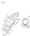
- Fig. 1 is an explanatory view showing a state where pulse-wave measuring apparatus for wearing on the user's arm (hereinafter referred to as "an arm-wear type" pulse wave measuring apparatus) according to a first embodiment is being used.
- Fig. 2 (a) is a plan view of an optical unit of a sensor unit (a detection unit) employed in the foregoing arm wear type pulse-wave measuring apparatus.
- Fig. 2 (b) is an explanatory view showing a state where a sensor securing band for the sensor unit employed in the arm wear type pulse-wave measuring apparatus is deployed.
- Fig. 2 (c) is an explanatory view showing the structure of another sensor unit.
- Fig. 3 is an explanatory view showing a state of the sensor unit put on the root of the finger and as well as showing the operation of the sensor unit.
- the arm wear type pulse-wave measuring apparatus 1 (an organism information measuring apparatus) according to this embodiment comprises an apparatus body 10 (a body of the pulse-wave measuring apparatus 1) having the structure of a wristwatch; a cable 20 (a signal transmission portion) connected to the apparatus body 10; and a sensor unit 30 disposed at the leading end of the cable 20.
- the apparatus body 10 is made detachable with respect to the arm by means of a wrist band 12.
- the sensor unit 30 has a sensor securing band 40 that is about 15 mm in width. The sensor securing band 40 enables the sensor unit 30 to be put on the root of the finger.
- the cable 20 extending from the sensor to unit 30 is provided with a connector portion 70 with which switching can be performed between a state where the cable 20 is connected to the apparatus body 10 and a state where the same is removed from the apparatus body 10, removal of the sensor unit 30 and the cable 20 from the apparatus body 10 enables the arm wear type pulse-wave measuring apparatus 1 to be used as a normal wristwatch.
- the apparatus body 10 comprises a watch case 11 including a time measuring function portion.
- the watch case 11 has, on the upper surface thereof, a liquid crystal display unit 13 (a display portion) for displaying, in addition to the present time and date, information about pulse waves (information about the organism) in accordance with results of detection obtained by the sensor unit 30.
- the watch case 11 includes a data processing circuit 50 for processing, for example, a detection signal to display changes in the pulse rate or and the like in accordance with the results of the detection obtained by the sensor unit 30.
- the data processing circuit 50 and the liquid crystal display unit 13 form an organism information display portion 60.
- the watch case 11 has, on the outer surface thereof, button switches 111, 112, 113, 114 and 115 for adjusting time and switching the display mode.
- Electric power is supplied to the arm wear type pulse-wave measuring apparatus 1 from a battery (not shown) included in the watch case 11.
- the cable 20 is used to supply electric power from the battery to the sensor unit 30 and to input the results of the detection obtained by the sensor unit 30 to the data processing circuit 50.
- the sensor unit 30 comprises the sensor securing band 40 and an optical unit 300.
- the sensor securing band 40 is made of a resin molded member having a thickness which permits flexibility so that the sensor securing band 40 is curled up in its natural state. In order to mount the sensor on the finger, the sensor securing band 40 is uncurled, followed by being wound around the root of the finger. When the sensor has been mounted on the finger it remains in place due to the shape restoring force of the securing band 40.
- the sensor securing band 40 has a thick portion at substantially the central portion thereof, the thick portion having a hole 41 that is capable of accommodating the optical unit 300.
- the optical unit 300 is, with resin, molded into a rectangular shape having a pair of projection portions 311 and 312 on the two sides thereof.
- the cable 20 is extended from the inside portion of the optical unit 300.
- the hole 41 of the sensor securing band 40 has the shape and size which permit accommodation of the optical unit 300 therein.
- the hole 41 has concavities 411 and 412 for receiving the projections 311 and 312 when the optical unit 300 is placed in the hole 41 so that undesirable separation is prevented.
- the sensor securing band 40 has four narrow portions 410 for easily putting the sensor securing band 40 on the finger.
- the width of the sensor securing band 40 may be about 20 mm to 25 mm.
- a structure may be employed in which only a portion of the sensor securing band 40, to which the optical unit 300 is attached, is widened.
- the sensor securing member that is typified by the sensor securing band 40, it may be in the form of a ring-like shape that is put on the finger, as well as in the form of the band type shape that is wound around the finger.
- An example of the sensor securing member has a hollow and cylindrical shape made of fibre, such as rubber, rendering it resiliently deformable so that it can clamp itself on the finger.
- the foregoing member has a structure, in which the sensor unit 30 is enclosed in the ring-like shape, in place of the band-like structure according to this embodiment. Therefore, the foregoing sensor securing member is put on the finger in such a manner that it is received by the leading end of the finger, followed by being moved to the root of the finger, instead of being wound around the finger.
- the method of securing the sensor unit 30 either of the foregoing sensor securing members may be employed.
- the hole 41 according to this embodiment so formed in the sensor securing band 40 as to accommodate the sensor unit 30 may be omitted from the structure. That is, the sensor securing member and the sensor unit 30 have independent shapes in the foregoing case. In the foregoing case, the sensor unit 30 is held by the hand when the sensor securing band 40 is wound around the finger.
- an LED 31 irradiates the finger with light, and light reflected by the organism (the blood vessel) is received by a phototransistor 32 so as to detect pulse waves from the blood vessel.
- the optical unit 300 has the outer shape formed by a sensor frame 301 serving as the case body, a reverse cover 302 and a glass plate 304, and a circuit board 305 (Figs. 4 and 5) opposing the glass plate 304.
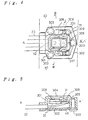
- Fig. 4 is a plan view of the optical unit 300
- Fig. 5 is a cross sectional view taken along line A-A' of Fig. 4
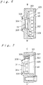
- Fig. 6 is a cross sectional view taken along line B-B' of Fig. 4
- Fig. 7 is a cross sectional view taken along line C-C' of Fig. 4.
- the reverse cover 302 is mounted on the sensor frame 301 serving as the case body of the optical unit 300 so that the internal portion serves as a space for accommodating elements.
- the reverse cover 302 is secured to the sensor frame 301 with three reverse-cover securing screws 303.
- the reverse-cover securing screws 303 secure the sensor securing band 40 to the lower surface of the reverse cover 302, while the sensor securing band 40 extends from the optical unit 300 into the two side directions.
- the cable 20 is extended from the inside portion of the sensor frame 301 in a direction perpendicular to the sensor securing band 40.
- the glass plate 304 serves as an optical filter and has a light transmissive window on the upper surface of the sensor frame 301.
- the circuit board 305 is so secured in the sensor frame 301 as to oppose the glass plate 304.
- Circuit board 305 Electronic parts, such as an LED 31, a phototransistor 32 (a sensor unit having a filter), a transistor 309, resistors and capacitors (not shown), are mounted on the circuit board 305.
- the light emitting surface and the light receiving surface of the corresponding LED 31 and the phototransistor 32 are caused to face the glass plate 304.
- the circuit board 305 is secured to the sensor frame 301 in such a manner that circuit-board securing threads 307 are fastened by two pins 306 inserted from the upper surface of the sensor frame 301.
- an earth plate 308 is secured by the pins 306.
- This embodiment is characterized in that a blue LED made of InGaN (Indium-Gallium-Nitrogen type) material is employed to serve as the LED 31.
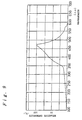
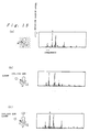
- the emission spectrum of the LED 31 has the emission peak at 450 nm as shown in Fig. 8, while the emission wavelength region of the same ranges from 350 nm to 600 nm.
- a GaAsP (Gallium-Arsenic-phosphorus type) phototransistor is employed as the phototransistor 32 because it is suitable for use with the LED 31 having the foregoing light emission characteristics.
- the light receiving wavelength region of the phototransistor 32 is, as shown in Fig. 9, such that the main sensitive region is in a range from 300 nm to 600 nm and also a sensitive region exists in a region lower than 300 nm.
- a sensor unit of a type having an optical filter attached to the device may be employed as the phototransistor 32.
- An example of the light receiving wavelength region of the sensor unit of this type is, as shown in Fig. 10, the main sensitive region being in a range from 400 nm to 550 nm.
- the LED 31 and the phototransistor 32 consume a relatively small amount of electric power, a long operation time can be realized even if one small-size battery is used, for example, to operate the arm wear type pulse-wave measuring apparatus 1 having the time measuring function and the pulse wave measuring function.
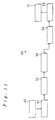
- FIG. 11 is a block diagram showing the structure of the data processing circuit 50.
- a pulse-wave signal conversion portion 51 converts a signal supplied from the sensor unit 30 through the cable 20 into a digital signal to transmit the digital signal to a pulse-wave storage portion 52.
- the pulse-wave storage portion 52 is a RAM for storing pulse wave data converted into the digital signal.
- a pulse-wave signal calculating portion 53 reads the signal stored in the pulse-wave storage portion 52 to analyze the frequency of the signal so as to transmit results of the analysis to a pulse-wave component extraction portion 54.
- the pulse-wave component extraction portion 54 extracts the pulse wave component from the signal supplied from the pulse-wave signal calculating portion 53 to transmit the extracted component to a pulse-rate calculating portion 55.
- the pulse-rate calculating portion 55 calculates the pulse rate in accordance with the frequency component of the supplied pulse waves to transmit results of the calculation to the liquid crystal display unit 13.
- the apparatus body 10 is put on the arm by means of the wrist band 12 in a state where the cable 20 and the sensor unit 30 are removed from the connector portion 70 of the apparatus body 10.
- the arm wear type pulse-wave measuring apparatus 1 is used to measure information about pulse waves, such as the pulse rate, during exercise, such as jogging or running
- the cable 20 is connected to the connector portion 70 of the apparatus body 10, and then the apparatus body 10 is put on the arm by means of the wrist band 12.
- the sensor unit 30 the glass plate 304 of the optical unit 300
- exercise such as jogging or running
- the data processing circuit 50 shown in Fig. 11 converts the signal supplied from the phototransistor 32 (the sensor unit 30) into a digital signal to analyze the frequency of the digital signal to calculate the pulse rate.
- the pulse rate obtained due to the calculation is displayed on the liquid crystal display unit 13. That is, the arm wear type pulse-wave measuring apparatus 1 serves as a pulsimeter.
- a portion of light emitted by the LED 31 is allowed to pass through the finger to reach the blood vessel 500 as indicated by an arrow C.
- reflected light from the hemoglobin in the blood reaches the phototransistor 32, as indicated by an arrow D.
- the quantity of light received through the foregoing route is the quantity of light reflected by the organism.
- a portion of light emitted by the LED 31 is reflected by the surface of the finger as indicated by an arrow E to reach the phototransistor 32.
- the quantity of light received through the foregoing route is the quantity of light reflected by the skin.
- a portion of light emitted by the LED 31 and that reflected by the blood vessel are absorbed or dispersed in the finger, as indicated by arrows F and G, so that the portions of the light do not reach the phototransistor 32.
- the sensor unit 30 comprises the LED 31, the light emission wavelength region of which is in the range from 350 nm to 600 nm; and the phototransistor 32, the main light receiving wavelength region of which is in the range from 300 nm to 600 nm.
- the main light receiving wavelength region of which is in the range from 300 nm to 600 nm.
- the foregoing sensor unit 30 By using the foregoing sensor unit 30, light included in external light, the wavelength region of which is shorter than 700 nm, does not reach the phototransistor 32 (the light receiving portion) through the finger serving as a phototransistor, as described later. On the other hand, light, the wavelength of which is shorter than 300 nm, is substantially absorbed by the surface of the skin. Therefore, the results of the detection are not affected by external light. Thus, in accordance with the results of the detection in the wavelength region from 300 nm to 700 nm obtained due to only light from the light emitting portion, information about an organism can be measured.
- the LED 31 may be an LED having the light emission wavelength region of 300 nm to 700 nm and the phototransistor 32 may be a phototransistor having the light receiving wavelength region of 700 nm or shorter.
- the arm wear type pulse-wave measuring apparatus 1 comprises the LED 31 having the light emission wavelength region of 350 nm to 600 nm, and the phototransistor 32 having the main sensitive region of the light receiving wavelength region of 300 nm to 600 nm.
- the phototransistor 32 is a unit formed by combining the device and the filter, the light receiving wavelength region is in a range from 400 nm to 550 nm. Therefore, if the pulse waves are measured in the simple light shielding state shown in Fig. 1, light included in external light that has the wavelength region of 700 nm or shorter does not reach the phototransistor 32 (the light receiving portion) through the finger serving as the photoconductor.
- the small sensor unit 30 enables the user to lightly clench the fist with the same put on the root of the finger thereof so that no problem arises during exercise, such as jogging, running or cycling.
- the arm wear type pulse-wave measuring apparatus 1 is suitable to measure the pulse rate during exercise, such as jogging.
- the temperature of the fingertip is lowered considerably when the ambient temperature is low, whereas the temperature of the root of the finger is lowered much less, or not at all. That is, the bloodstream is not lowered considerably at the root of the finger.
- the information about an organism, such as the pulse rate can accurately be measured if the user performs exercise outdoors, such as running, in a cold day.
- the information about pulse waves is obtained by using light having the wavelength region from about 300 nm to about 700 nm, the S/N ratio of the pulse wave signal in accordance with the change in the quantity of the blood is high. The reason for this will be described later.
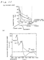
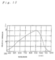
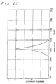
- Fig. 12 (a) shows the relationship between the wavelength of light and light transmittance of the skin.
- Polygonal line a indicates transmission characteristic with respect to light having a wavelength of 200 nm
- polygonal line b indicates transmission characteristic with respect to light having a wavelength of 300 nm
- polygonal line c indicates transmission characteristic with respect to light having a wavelength of 500 nm
- polygonal line d indicates transmission characteristic with respect to light having a wavelength of 700 nm
- polygonal line e indicates transmission characteristic with respect to light having a wavelength of 1 ⁇ m.
- the arm wear type pulse-wave measuring apparatus 1 can be used outdoors. Since a major portion of light in a wavelength region lower than 300 nm is absorbed in the surface of the skin, the substantial light receiving wavelength region is 300 nm to 700 nm even if the light receiving wavelength region is made to be 700 nm or shorter.
- the conventional optical system detects pulse waves in accordance with results of detection by means of light included in external light that has a wavelength of 1 ⁇ m that easily reaches the light receiving portion through the finger serving as the photoconductor as indicated by arrow Y shown in Fig. 3, that is, light indicated by polygonal line e of Fig. 12 (a), erroneous detection easily takes place due to change in external light.
- Fig. 12 (b) is a graph of explanatory showing the relationship between wavelengths of light and light absorption characteristics of a variety of hemoglobin.
- Fig. 12 (b) shows, with curve Hb, the light absorption characteristics of hemoglobin that has not been bonded with oxygen and light absorption characteristics of hemoglobin that has been bonded with oxygen with curve HbO 2 .
- hemoglobin in the blood has a large light absorption factor with respect to light having a wavelength of 300 nm to 700 nm, the light absorption factor being several times to about 100 times the light absorption factor with respect to light having the wavelength of 880 nm which is the conventional detection light.
- the detection values change in accordance with the change in the quantity of blood, with excellent sensitivity attained. Therefore, a high detection ratio (the S/N ratio) of the pulse waves in accordance with change in the quantity of blood can be obtained.
- condition 1 was a state where the root of the finger was covered with the light shielding cover having a width of 10 mm as shown in Fig. 14 (a)
- condition 2 was a state where the root of the finger was covered with the light shielding cover having a width of 20 mm as shown in Fig. 14 (b)
- condition 3 was a state where the root of the finger was covered with the light shielding cover having a width of 40 mm as shown in Fig. 14 (c)
- condition 4 was a state where the root of the finger was covered with the light shielding cover having a width of 70 mm as shown in Fig. 14 (d)
- condition 5 is a state where the overall body of the forefinger, the root of the thumb, the root of the middle finger and portions adjacent to the roots of all fingers were covered with a light shielding cover.
- the pulse-wave measuring apparatus 1 As shown in Table 1, the pulse-wave measuring apparatus 1 according to this embodiment (samples 1 and 2) receives light in the wavelength region from 300 nm to 700 nm so that influence of external light can be ignored under any of the foregoing conditions.
- the reason for this is that light included in external light that has the wavelength region of 700 nm or shorter does not reach the phototransistor 32 (the light receiving portion) through the finger serving as the photoconductor. Therefore, the pulse-wave measuring apparatus 1 according to this embodiment requires the finger to be covered with the sensor unit 30 or the sensor securing band 40 (the light shielding cover) only by a width of 10 mm.
- the pulse-wave measuring apparatus are able to ignore the influence of external light only in the state (condition 5) where the finger is covered widely such that the overall body of the forefinger, the root of the thumb, the root of the middle finger and portions adjacent to the roots of all fingers were covered with a light shielding cover.
- a large-scale light shielding structure is required.
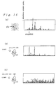
- the pulse-wave measuring apparatus 1 comprising the LED 31 (the blue light source) having the light emission wavelength peak of 450 nm; and the GaAsP type phototransistor 32 having the light receiving wavelength region of 300 nm to 600 nm; and the pulse-wave measuring apparatus (the comparative example) comprising the LED having the light emission wavelength peak of 880 nm and the phototransistor having the light receiving wavelength region of 350 nm to 1200 nm were used to compare and investigate the degree of influence of external light. Results were shown in Figs. 15 and 16. Data shown in Figs. 15 and 16 were results of analysis of the frequency to be used as the results of the detection of pulse waves. Among a multiplicity of peaks, peaks each given an arrow correspond to the frequency of the pulse waves.
- Fig. 15 (a) shows results of measurement of pulse waves when a user having the arm wear type pulse-wave measuring apparatus according to this embodiment runs in a dark room.
- Fig. 15 (b) shows results of measurement of pulse waves when the user having the arm wear type pulse-wave measuring apparatus according to this embodiment runs in a direction toward sunlight.
- Fig. 15 (c) shows results of measurement of pulse waves when the user having the arm wear type pulse-wave measuring apparatus according to this embodiment runs in a multiplicity of directions such that the relative direction of sunlight varied.
- the peaks of the pulse waves each of which is indicated by an arrow, is clear as compared with other peaks.
- the arm wear type pulse-wave measuring apparatus 1 according to this embodiment cannot easily be affected by external light.
- Fig. 16 (a) shows results of measurement of pulse waves when the user having the conventional arm wear type pulse-wave measuring apparatus 510 run in a dark room.
- Fig. 16 (b) shows results of measurement of pulse waves when the user having the conventional arm wear type pulse-wave measuring apparatus run in a direction toward the sunlight.
- Fig. 16 (c) shows results of measurement of pulse waves when the user having conventional the arm wear type pulse-wave measuring apparatus runs in a multiplicity of directions such that the relative direction of sunlight varied.
- the conventional pulse-wave measuring apparatus is able to measure the pulse waves only in the dark room, and the measurement cannot be performed under conditions where external light exists.
- the arm wear type pulse-wave measuring apparatus 1 according to this embodiment and the conventional pulse-wave measuring apparatus were used to compare and investigate the pulse wave signal level ( ⁇ A), the overall level of reflected light ( ⁇ A) and the ratio of the pulse wave signal included in reflected light, results being shown in Table 2.
- sample 6 comprising the LED 31 (that emits blue light) having the light emission wavelength region of 420 nm to 480 nm
- sample 7 comprising the LED 31 (that emits green light) having the light emission wavelength region of 540 nm to 570 nm were evaluated.
- Sample 7 comprised the GaP type LED 31 that emits green light.
- the GaP type LED 31 had the light emission spectrum as shown in Fig.
- Sample 7 comprising the foregoing GaP type LED 31 comprised the GaP type phototransistor 32 to be adaptable to the light emission characteristics of the LED 31.
- the GaP type phototransistor 32 had the light receiving sensitivity such that the sensitive region existed in a range from 200 nm to near 700 nm, as shown in Fig. 18.
- samples 8, 9 and 10 each having the light emission wavelength region that was out of the range from 300 nm to 700 nm were evaluated.
- the arm wear type pulse-wave measuring apparatus 1 (samples 6 and 7) according to this embodiment uses light having the light emission wavelength region of 300 nm to 700 nm to be adaptable to the wavelength region in which the light absorption factor of hemoglobin in the blood is large. Therefore, high ratios of pulse wave signals included in reflected light of 0.019 and 0.013 are attained; that is, excellent sensitivity can be obtained.
- the pulse-wave measuring apparatuses according to the comparative examples has low ratios of the pulse wave signals included in reflected light of less than 0.002; that is, the sensitivity is unsatisfactory. Namely, the sensitivity of the arm wear type pulse-wave measuring apparatus 1 according to this embodiment provides a significant improvement over the prior art such that the S/N ratio of the pulse wave signal can be raised to about 10 times that of the conventional structure.
- Results of investigation that the advantage of the significant sensitivity of the arm wear type pulse-wave measuring apparatus 1 according to this embodiment is not affected by the skin colour are shown in Table 3.
- the evaluation was performed by using the arm wear type pulse-wave measuring apparatus 1 (sample 11) comprising the LED (the blue light source) having the light emission wavelength peak of 450 nm that could not easily be reflected by the surface of the skin; and the conventional pulse-wave measuring apparatus (comparative example and sample 12) comprising the LED having the light emission wavelength peak of 880 nm that could easily be reflected by the surface of the skin.
- the pulse waves of the "yellow-skinned" races, "white” races and the “black” races were measured to calculate the quantity of reflection of light from the skins, the quantity of reflection of light from the organisms (the quantity of light from the blood vessels) and pulse wave components.
- the sensor unit according to the present invention can be put on another finger (the thumb, the middle finger, the ring finger or the little finger) as well as on the forefinger. If the sensor unit is put on any finger, the user is able to lightly clench the fist with the sensor unit put on the finger. Therefore, the user is able to select the finger on which the sensor unit is put as desired.
- a wireless method may be employed in place of the wired method typified by the cable 20 according to the foregoing embodiment. That is, a transmission circuit is included in the sensor unit or the sensor securing band or the like, on which the sensor unit is mounted; and a receiving circuit is included in the body of the apparatus.
- the distance from the transmitting portion (the root of the finger) to the receiving portion (arm) is very short so that only a very weak output of electric waves is required. Therefore, a very small transmission circuit/receiving circuit can be formed.
- a portion or the overall body of the sensor securing band may be used as an antenna of the transmission circuit.
- the light absorption characteristics of hemoglobin in the blood is, as shown in Fig. 12 (b), different between hemoglobin that has not been bonded with oxygen and hemoglobin that has been bonded with hemoglobin, use of light having the wavelength from 300 nm to 700 nm, for example, about 470 nm, as detection light enables the quantity of each hemoglobin and the total quantity of hemoglobin to be measured as information about an organism in accordance with the intensity of the detection light. Furthermore, the difference in the light absorption characteristics between the skin and water can be used to measure water contained in the skin as information about an organism.
- the arm wear type pulse-wave measuring apparatus (the organism information measuring apparatus) according to the present invention is characterized in that the fingertip or the like is irradiated with light by the light emitting portion, such as the LED; reflected light from the blood or the like is detected by the light receiving portion, such as the transistor; information about an organism is measured in accordance with results of detection in the wavelength region from 300 nm to 700 nm obtained by the foregoing detection means.
- the detection in the foregoing wavelength region determination of the wavelength region of the light emitting portion to be at least in the range from 300 nm to 700 nm and the light receiving wavelength region to be 700 nm or shorter causes light included in external light that has the wavelength region of 700 nm or shorter not to reach the light receiving portion through the finger serving as the photoconductor.
- light in the wavelength region shorter than 300 nm is substantially completely absorbed by the surface of the skin. Therefore, the results of the detection is not affected by external light, and information about an organism can be measured in accordance with the result of detection in the wavelength region from 300 nm to 700 nm according to only light from the light emitting portion.
- a large-scale light shielding structure is not required.
- the size of the sensor unit can be reduced to the size that enables the sensor unit to be put on the root of the finger.
- the foregoing small sensor unit enables the user to lightly clench the fist with the sensor unit put on, whereby no problem arises to perform exercise, such as jogging, running or cycling.
- the foregoing sensor unit is suitable when the pulse rate or the like is measured during exercise, such as jogging.
- the sensor unit put on the root of the finger enables the pulse rate or the like to be measured accurately even if a user performs exercise on a cold day.
- Hemoglobin in the blood has a light absorption factor with respect to light having the wavelength region in a range from 300 nm to 700 nm that is considerably larger than the light absorption factor with respect to infrared rays.
- the wavelength region of which is in the range from 300 nm to 700 nm is applied toward an organism to be adaptable to the light absorption characteristic of hemoglobin, the intensity of light reflected by the organism (the blood vessel) is considerably changed to follow the change in the quantity of blood.
- the S/N ratio of the pulse wave signal can be raised so that an effect is obtained with the arm wear type pulse-wave measuring apparatus according to the present invention in that excellent sensitivity can be attained in measuring the pulse waves.
- the structure of the present invention is suitable to form a portable pulse-wave measuring apparatus (organism information measuring apparatus) of an arm wear type, the power source of which is limited.
Landscapes
- Health & Medical Sciences (AREA)
- Life Sciences & Earth Sciences (AREA)
- Biomedical Technology (AREA)
- Molecular Biology (AREA)
- Veterinary Medicine (AREA)
- Biophysics (AREA)
- Pathology (AREA)
- Engineering & Computer Science (AREA)
- Cardiology (AREA)
- Heart & Thoracic Surgery (AREA)
- Medical Informatics (AREA)
- Physics & Mathematics (AREA)
- Surgery (AREA)
- Animal Behavior & Ethology (AREA)
- General Health & Medical Sciences (AREA)
- Public Health (AREA)
- Physiology (AREA)
- Physical Education & Sports Medicine (AREA)
- Measuring Pulse, Heart Rate, Blood Pressure Or Blood Flow (AREA)
Description
- The present invention relates to an organism information measuring apparatus, such as a pulse-wave measuring apparatus. The apparatus may display information about the pulse wave, such as the pulse rate. More particularly, but not exclusively, the present invention relates to an apparatus that irradiates an organism such as a blood vessel with light and detects light reflected by the organism to measure information about the organism, such as the pulse waves. The present invention also relates to a pulse-wave measuring apparatus which is worn on the user's arm, and which is capable of measuring information about the organism during an exercise, such as jogging, running or cycling.
- Devices for detecting information (such as pulse waves) from an organism (such as a blood vessel) include electronic apparatus of a type that optically detects changes in the quantity of blood to display information about an organism in accordance with results of the detection. In an optical pulse-wave measuring apparatus (an organism information measuring apparatus) of the foregoing type, a light emitting device, such as an LED (Light Emitting Diode), irradiates the fingertip or the like with light, and light reflected by the organism (the blood vessel) is received by a light receiving device, such as a phototransistor, so that changes in the quantity of blood passing through the blood vessel occurring due to the pulse waves of the blood are detected as changes in the quantity of the received light. In response to a pulse wave signal obtained by the detection, changes in the pulse rate or the pulse waves are displayed. As the light to be emitted for radiation from the light emitting device, infrared rays have been employed. If external light (sunlight or the like) is incident upon the light receiving device this causes the quantity of received light to change. Therefore, the conventional pulse-wave measuring apparatus employs a light shielding cover to cover the area, such as on the fingertip, where light detection occurs so that the influence of the external light is prevented or reduced.
- However, use of the apparatus in a place, such as outdoors, where it is irradiated with external light results in a portion of the external light passing through the finger and reaching the light receiving device. Thus, the conventional pulse-wave measuring apparatus has a problem in that the change in the illuminance of external light causes pulse waves to be detected erroneously even when the area where light is detected is covered. Therefore, the conventional pulse-wave measuring apparatus encounters a limitation in that it can be used only in a place that is not irradiated with external light or a place in which the constant illuminance of external light can be attained. To overcome the foregoing limitation, a larger-scale light shielding structure must be provided to prevent influence of external light which passes through the finger. Therefore, the size of the pulse-wave measuring apparatus cannot be reduced, and the conventional pulse-wave measuring apparatus cannot be used as an apparatus that is able to measure information about pulse waves during exercise, such as jogging, running or cycling.
- DE 2805202A describes a pulse monitor of the above type which may be in the form of a wristwatch. The monitor utilises a light emitting diode which emits light having a wavelength in the range of 600 to 650 nm.
- To overcome the foregoing problem, a pulse-wave sensor has been disclosed in Japanese Utility-Model Laid-Open No. 57-74009 which, in addition to the device for detecting pulse waves, comprises an external-light detection device for detecting external light and which compensates for the influence of external light in accordance with results of the detection of external light obtained by the external-light detection device. However, provision of the external-light detection device and a compensation circuit for the pulse waves sensor prevents size and cost reductions.
- As described above, any of the conventional countermeasures against external light has been unsatisfactory in view of practical use.
- Furthermore, there has been a requirement for a pulse-wave measuring apparatus of the foregoing type which is worn on the arm and that is capable of measuring the pulse rate of the wearer and the like during jogging, running, cycling or a marathon race. To provide a pulse-wave measuring apparatus of this type, a small sensor unit is required which can be put on the root of the finger (i.e. the part of the finger closest to the palm of the hand). This is because, if a small sensor is put on the root of the finger, the wearer is able to lightly clench the fist.
- GB 2052050A describes a pulse wave monitor in the form of a watch provided with a remote sensing feature which is arranged for mounting on the finger of a user. The remote sensor is coupled to the watch by a cable and information regarding the user's pulse is displayed on the face of the watch.
- In view of the foregoing, the inventors of the present invention have performed a variety of investigations into the reasons why pulse waves are erroneously detected due to changes in the illuminance of external light. As a result, it is concluded that infrared rays for use in the detection system of the conventional pulse-wave measuring apparatus have an excessively large transmittance with respect to the organism that causes external light to easily reach the light receiving device through the organism even if a light shielding cover is provided. Thus, if the foregoing problem can be overcome, a practical countermeasure against external light can be provided.
- Accordingly, an object of the present invention is to realize an organism information measuring apparatus having an optical system, which is not easily affected by external light, to omit a large-scale light shielding structure and to overcome the limitations of conditions for use.
- According to a first aspect of the present invention there is provided an organism information measuring apparatus comprising:
- a light emitting means for irradiating a portion of an organism of a person with light;
- a detection means having a light receiving means for receiving light emitted by the light emitting means and reflected by the portion of the organism; characterised in that said light receiving means is arranged to detect only light having a wavelength of substantially 700 nm or less, such that the measuring apparatus can be arranged to provide information about the organism on the basis of light transmitted from the light emitting means and reflected by the portion of the organism but not to provide information arising from external light incident on the person and having a wavelength of substantially 700nm or more which is able to propagate through skin tissue of the person to the light receiving means.
-
- Preferably, the light emitting means has a light emitting wavelength region at least in a range from substantially 300 nm to substantially 700 nm.
- Advantageously the apparatus is characterised by an organism information display portion for displaying information about the organism on the basis of light detected by the receiving means, the light having a wavelength of substantially 700 nm or less.
- Another object of the present invention is to provide a pulse-wave measuring apparatus for wearing on the arm having a sensor unit of a small size for mounting on a finger that does not obstruct a user from performing exercises, and such as jogging, and which is capable of measuring information such as the pulse rate.
- Accordingly, the apparatus is characterised in that the measuring apparatus is arranged to be worn on an arm of a person and comprises;
a sensor unit including the light emitting means and the light receiving means, securing means for securing said sensor unit in such a manner that a light receiving surface of said light receiving means and a light emitting surface of said light emitting means face the surface of a finger of the person;
a body portion having a display portion for displaying information about pulse waves of the person obtained in accordance with results of receipt of light performed by said light receiving means;
a wrist band for securing said body portion on the arm of the person;
a signal transmission portion which extends from said sensor unit to said body portion and through which a signal representative of the light received by said light receiving means is input to said body portion;
wherein said information about pulse waves is displayed on the basis of light detected by the receiving means, the light having a wavelength of substantially 700 nm or less; and
said sensor unit has a size such that said sensor unit may be mounted on the root of the finger of the person. - The sensor unit may be used in a state where the sensor unit is put on the region from the root of the finger to the joint of the finger so that a user is able to lightly clench the fist if the sensor unit is put on the finger.
- It is preferable that an InGaN type (Indium-Gallium-Nitrogen type) blue LED be employed as the light emitting portion, and a GaAsP type (Gallium-Arsenic-phosphorus type) phototransistor be employed as the light receiving portion.
- According to a further aspect of the present invention there is provided a method of measuring the pulse rate of a person, including irradiating a portion of an organism of the person with light from a light emitting means and detecting the light by a detection means having a light receiving means, characterised in that only light having a wavelength of 700nm or less is detected such that the pulse rate can be measured on the basis of the light from the light emitting means and not on the basis of external light incident on the person and having a wavelength of substantially 700nm or more which is able to propagate through skin tissue of the person to the light receiving means.
- Preferably, irradiation is performed on a blood vessel in the root of the finger or thumb of a person.
- Therefore, erroneous detection of pulse waves due to external light can be prevented so far as external light is not directly made incident upon the detection portion. Thus, a large-scale light shielding structure is not required.
- As a result, even if a small sensor unit, that can be put on a portion from the root to the knuckle of the thumb, the middle finger, the ring finger or the little finger. is used, external light can satisfactorily be shielded. If the foregoing small sensor unit is used, it does not cover the finger when it is put on the root of the finger whereby allowing a user to lightly clench the fist. Thus, no problem arises during exercise, such as jogging, running or cycling.
- Hemoglobin in the blood has a light absorption factor with respect to light having a wavelength region in a range from 300 nm to 700 nm which is considerably larger than the light absorption factor with respect to infrared rays. When an organism is irradiated with light having the wavelength region in the range from 300 nm to 700 nm to be adaptable to the light absorption characteristics of hemoglobin, the intensity of light reflected by the organism (the blood vessel) is considerably changed to follow the change in the quantity of the blood. Therefore, the S/N ratio of the pulse wave signal can be raised.
- As a result of measurement of the distribution of body temperature from the palm to the fingertip, the temperature of the fingertip is considerably lowered when the ambient temperature is low. On the other hand, the temperature of the root of the finger cannot relatively be lowered. That is, the bloodstream at the root of the finger is not reduced excessively even in a cold day. Therefore, putting of the sensor unit at the root of the finger enables information about an organism such as the pulse rate, to be accurately measured if a user performs exercise outdoors, such as running. The method according to an embodiment of the present invention is an excellent measuring method that cannot be obtained by a so-called finger acuminate pulse wave measuring method that is a conventional method for measuring the bloodstream at the fingertip.
- In one embodiment a pulse rate measuring apparatus is provided including light emitting means for irradiating a blood vessel with light, and a light detecting means for detecting the light after it has irradiated the blood vessel. The light detecting means is sensitive to light having a wavelength of substantially 700 nm or less. The light emitting and light detecting means are mounted on one side of a sensor securing band. When the apparatus is in use the securing band is positioned on the user's body such that the light emitting and detecting means are located in a space between the sensor securing band and the skin of the user. The sensor securing band acts as a shield to external light and prevents it from directly irradiating the light detecting means. Light having a wavelength shorter than 700 nm cannot easily penetrate and/or is easily absorbed by the skin. Therefore, external light does not irradiate the light detecting means because: (i) light having a wavelength shorter than 700 nm which irradiates the skin around the sensor securing band does not penetrate the skin or is absorbed easily by the skin before it reaches the light detecting means, and (ii) light having a wavelength longer than 700 nm is outside the range of sensitivity of the light detecting means. Thus, the sensor securing band may be relatively small and cover an area of the skin substantially equal to the size of the light emitting and detecting means.
- For a better understanding of the invention, embodiments will now be described by way of example with reference to the accompanying drawings, in which:
- Fig. 1 is an explanatory view showing a state where a pulse-wave measuring apparatus for wearing on the arm (an organism information detecting apparatus) according to an embodiment of the present invention is used;
- Fig. 2 (a) is a plan view of an optical unit of a sensor unit (a detection unit) for use in the pulse-wave measuring apparatus shown in Fig. 1;
- Fig. 2 (b) is an explanatory view showing a state where a sensor securing band of the sensor unit (the detection unit) for use in the pulse-wave measuring apparatus is deployed;
- Fig. 2 (c) is an explanatory view showing the structure of another sensor unit (a detection unit);
- Fig. 3 is an explanatory view showing a state of the sensor unit of the pulse-wave measuring apparatus shown in Fig. 1 put on the root of the finger and the operation of the same;
- Fig. 4 is a plan view showing the structure of the detection unit (the optical unit) of the pulse-wave measuring apparatus shown in Fig. 1;
- Fig. 5 is a cross sectional view taken along line A-A' of Fig. 4;
- Fig. 6 is a cross sectional view taken along line B-B' of Fig. 4;
- Fig. 7 is a cross sectional view taken along line C-C' of Fig. 4;
- Fig. 8 is an explanatory graph showing the light emission spectrum of an InGaN type blue LED for use in the pulse-wave measuring apparatus shown in Fig. 1;
- Fig. 9 is an explanatory graph showing the light receiving characteristics of the InGaP type phototransistor for use in the pulse-wave measuring apparatus shown in Fig. 1;
- Fig. 10 is an explanatory graph showing the light receiving characteristics of a phototransistor unit having an optical filter for use in the pulse-wave measuring apparatus shown in Fig. 1;
- Fig. 11 is a block diagram showing the structure of a data processing circuit of the pulse-wave measuring apparatus shown in Fig. 1;
- Fig. 12 (a) is a graph showing the relationship between the wavelength of light and light transmittance of the skin;
- Fig. 12 (b) is an explanatory graph showing the relationship between the wavelength of light and the light absorption factors of various hemoglobin;
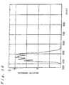
- Fig. 13 is an explanatory graph showing the light receiving characteristics of a silicon type phototransistor for use in a conventional pulse-wave measuring apparatus;
- Figs. 14(a) to (e) show respective experimental conditions in which the amount of the finger which is shielded from light is changed to evaluate the degree of introduction of external light into the arm wear type pulse-wave measuring apparatus according to the present invention;
- Figs. 15(a) to (c) show the results of analysis of the frequency of results of detection of pulse waves of the pulse-wave measuring apparatus according to the present invention to evaluate influence of external light upon the arm wear type pulse-wave measuring apparatus according to the present invention;
- Figs. 16(a) to (c) show the results of analysis of the frequency of results of detection of pulse waves of a pulse-wave measuring apparatus according to a comparative example to evaluate influence of external light upon the arm wear type pulse-wave measuring apparatus according to the present invention;
- Fig. 17 is an explanatory graph showing light emission spectrum of a GaP type LED for use in the pulse-wave measuring apparatus shown in Fig. 1; and
- Fig. 18 is an explanatory graph showing light receiving characteristics of a GaAsP type phototransistor for use in the pulse-wave measuring apparatus shown in Fig. 1.
-
- Fig. 1 is an explanatory view showing a state where pulse-wave measuring apparatus for wearing on the user's arm (hereinafter referred to as "an arm-wear type" pulse wave measuring apparatus) according to a first embodiment is being used. Fig. 2 (a) is a plan view of an optical unit of a sensor unit (a detection unit) employed in the foregoing arm wear type pulse-wave measuring apparatus. Fig. 2 (b) is an explanatory view showing a state where a sensor securing band for the sensor unit employed in the arm wear type pulse-wave measuring apparatus is deployed. Fig. 2 (c) is an explanatory view showing the structure of another sensor unit. Fig. 3 is an explanatory view showing a state of the sensor unit put on the root of the finger and as well as showing the operation of the sensor unit.
- Referring to Fig. 1, the arm wear type pulse-wave measuring apparatus 1 (an organism information measuring apparatus) according to this embodiment comprises an apparatus body 10 (a body of the pulse-wave measuring apparatus 1) having the structure of a wristwatch; a cable 20 (a signal transmission portion) connected to the
apparatus body 10; and asensor unit 30 disposed at the leading end of thecable 20. Theapparatus body 10 is made detachable with respect to the arm by means of awrist band 12. Thesensor unit 30 has asensor securing band 40 that is about 15 mm in width. Thesensor securing band 40 enables thesensor unit 30 to be put on the root of the finger. Since thecable 20 extending from the sensor tounit 30 is provided with aconnector portion 70 with which switching can be performed between a state where thecable 20 is connected to theapparatus body 10 and a state where the same is removed from theapparatus body 10, removal of thesensor unit 30 and thecable 20 from theapparatus body 10 enables the arm wear type pulse-wave measuring apparatus 1 to be used as a normal wristwatch. - The
apparatus body 10 comprises awatch case 11 including a time measuring function portion. Thewatch case 11 has, on the upper surface thereof, a liquid crystal display unit 13 (a display portion) for displaying, in addition to the present time and date, information about pulse waves (information about the organism) in accordance with results of detection obtained by thesensor unit 30. Thewatch case 11 includes adata processing circuit 50 for processing, for example, a detection signal to display changes in the pulse rate or and the like in accordance with the results of the detection obtained by thesensor unit 30. Thedata processing circuit 50 and the liquidcrystal display unit 13 form an organisminformation display portion 60. Note that thewatch case 11 has, on the outer surface thereof, button switches 111, 112, 113, 114 and 115 for adjusting time and switching the display mode. - Electric power is supplied to the arm wear type pulse-
wave measuring apparatus 1 from a battery (not shown) included in thewatch case 11. Thecable 20 is used to supply electric power from the battery to thesensor unit 30 and to input the results of the detection obtained by thesensor unit 30 to thedata processing circuit 50. - The
sensor unit 30 comprises thesensor securing band 40 and anoptical unit 300. Thesensor securing band 40 is made of a resin molded member having a thickness which permits flexibility so that thesensor securing band 40 is curled up in its natural state. In order to mount the sensor on the finger, thesensor securing band 40 is uncurled, followed by being wound around the root of the finger. When the sensor has been mounted on the finger it remains in place due to the shape restoring force of the securingband 40. - The
sensor securing band 40 has a thick portion at substantially the central portion thereof, the thick portion having ahole 41 that is capable of accommodating theoptical unit 300. - As shown in Fig. 2 (a), the
optical unit 300 is, with resin, molded into a rectangular shape having a pair ofprojection portions cable 20 is extended from the inside portion of theoptical unit 300. On the other hand, as shown in Fig. 2 (b), thehole 41 of thesensor securing band 40 has the shape and size which permit accommodation of theoptical unit 300 therein. Thehole 41 hasconcavities projections optical unit 300 is placed in thehole 41 so that undesirable separation is prevented. Thesensor securing band 40 has fournarrow portions 410 for easily putting thesensor securing band 40 on the finger. - In view of the
sensor unit 30 being required to enable the fist to be clenched lightly in a state where the same is put on the root of the finger, the width of thesensor securing band 40 may be about 20 mm to 25 mm. As shown in Fig. 2 (c), a structure may be employed in which only a portion of thesensor securing band 40, to which theoptical unit 300 is attached, is widened. - As the sensor securing member, that is typified by the
sensor securing band 40, it may be in the form of a ring-like shape that is put on the finger, as well as in the form of the band type shape that is wound around the finger. An example of the sensor securing member has a hollow and cylindrical shape made of fibre, such as rubber, rendering it resiliently deformable so that it can clamp itself on the finger. The foregoing member has a structure, in which thesensor unit 30 is enclosed in the ring-like shape, in place of the band-like structure according to this embodiment. Therefore, the foregoing sensor securing member is put on the finger in such a manner that it is received by the leading end of the finger, followed by being moved to the root of the finger, instead of being wound around the finger. - As the method of securing the
sensor unit 30, either of the foregoing sensor securing members may be employed. Thehole 41 according to this embodiment so formed in thesensor securing band 40 as to accommodate thesensor unit 30 may be omitted from the structure. That is, the sensor securing member and thesensor unit 30 have independent shapes in the foregoing case. In the foregoing case, thesensor unit 30 is held by the hand when thesensor securing band 40 is wound around the finger. By employing the foregoing method, the shape of thesensor securing band 40 and that of thesensor unit 30 can be simplified so that advantages are obtained in that the manufacturing process can be performed easily and that the cost can be reduced. - In this embodiment, as shown in Fig. 3, an
LED 31 irradiates the finger with light, and light reflected by the organism (the blood vessel) is received by aphototransistor 32 so as to detect pulse waves from the blood vessel. - Referring to Fig. 3, the
optical unit 300 has the outer shape formed by asensor frame 301 serving as the case body, areverse cover 302 and aglass plate 304, and a circuit board 305 (Figs. 4 and 5) opposing theglass plate 304. - Referring to Figs. 4 to 7, the structure of the
optical unit 300 will now be described in detail. Fig. 4 is a plan view of theoptical unit 300, Fig. 5 is a cross sectional view taken along line A-A' of Fig. 4, Fig. 6 is a cross sectional view taken along line B-B' of Fig. 4, and Fig. 7 is a cross sectional view taken along line C-C' of Fig. 4. - As shown in the foregoing figures, the
reverse cover 302 is mounted on thesensor frame 301 serving as the case body of theoptical unit 300 so that the internal portion serves as a space for accommodating elements. Thereverse cover 302 is secured to thesensor frame 301 with three reverse-cover securing screws 303. The reverse-cover securing screws 303 secure thesensor securing band 40 to the lower surface of thereverse cover 302, while thesensor securing band 40 extends from theoptical unit 300 into the two side directions. Thecable 20 is extended from the inside portion of thesensor frame 301 in a direction perpendicular to thesensor securing band 40. Theglass plate 304 serves as an optical filter and has a light transmissive window on the upper surface of thesensor frame 301. Thecircuit board 305 is so secured in thesensor frame 301 as to oppose theglass plate 304. - Electronic parts, such as an
LED 31, a phototransistor 32 (a sensor unit having a filter), atransistor 309, resistors and capacitors (not shown), are mounted on thecircuit board 305. The light emitting surface and the light receiving surface of the correspondingLED 31 and thephototransistor 32 are caused to face theglass plate 304. Note that thecircuit board 305 is secured to thesensor frame 301 in such a manner that circuit-board securing threads 307 are fastened by twopins 306 inserted from the upper surface of thesensor frame 301. Also anearth plate 308 is secured by thepins 306. - This embodiment is characterized in that a blue LED made of InGaN (Indium-Gallium-Nitrogen type) material is employed to serve as the
LED 31. The emission spectrum of theLED 31 has the emission peak at 450 nm as shown in Fig. 8, while the emission wavelength region of the same ranges from 350 nm to 600 nm. - A GaAsP (Gallium-Arsenic-phosphorus type) phototransistor is employed as the
phototransistor 32 because it is suitable for use with theLED 31 having the foregoing light emission characteristics. The light receiving wavelength region of thephototransistor 32 is, as shown in Fig. 9, such that the main sensitive region is in a range from 300 nm to 600 nm and also a sensitive region exists in a region lower than 300 nm. As thephototransistor 32, a sensor unit of a type having an optical filter attached to the device may be employed. An example of the light receiving wavelength region of the sensor unit of this type is, as shown in Fig. 10, the main sensitive region being in a range from 400 nm to 550 nm. Since theLED 31 and thephototransistor 32 consume a relatively small amount of electric power, a long operation time can be realized even if one small-size battery is used, for example, to operate the arm wear type pulse-wave measuring apparatus 1 having the time measuring function and the pulse wave measuring function. - Referring to Fig. 11, the structure of the
data processing circuit 50 disposed in thewatch case 11 will now be described. Fig. 11 is a block diagram showing the structure of thedata processing circuit 50. - In the
data processing circuit 50, a pulse-wavesignal conversion portion 51 converts a signal supplied from thesensor unit 30 through thecable 20 into a digital signal to transmit the digital signal to a pulse-wave storage portion 52. The pulse-wave storage portion 52 is a RAM for storing pulse wave data converted into the digital signal. A pulse-wavesignal calculating portion 53 reads the signal stored in the pulse-wave storage portion 52 to analyze the frequency of the signal so as to transmit results of the analysis to a pulse-wavecomponent extraction portion 54. The pulse-wavecomponent extraction portion 54 extracts the pulse wave component from the signal supplied from the pulse-wavesignal calculating portion 53 to transmit the extracted component to a pulse-rate calculating portion 55. The pulse-rate calculating portion 55 calculates the pulse rate in accordance with the frequency component of the supplied pulse waves to transmit results of the calculation to the liquidcrystal display unit 13. - The operation of the thus-constituted arm wear type pulse-
wave measuring apparatus 1 will now be described briefly with reference to Figs. 1, 3 and 11. - Referring to Fig. 1, when the arm wear type pulse-
wave measuring apparatus 1 is used as a normal wristwatch, theapparatus body 10 is put on the arm by means of thewrist band 12 in a state where thecable 20 and thesensor unit 30 are removed from theconnector portion 70 of theapparatus body 10. - In a case where the arm wear type pulse-
wave measuring apparatus 1 is used to measure information about pulse waves, such as the pulse rate, during exercise, such as jogging or running, thecable 20 is connected to theconnector portion 70 of theapparatus body 10, and then theapparatus body 10 is put on the arm by means of thewrist band 12. After the sensor unit 30 (theglass plate 304 of the optical unit 300) has been brought into close contact with the finger by thesensor securing band 40, exercise, such as jogging or running, is performed. - In the foregoing state, when the
LED 31 emits light to the finger as schematically shown in Fig. 3, light reaches the blood vessel, and a portion of light is absorbed by the hemoglobin in the blood. Another portion of light is reflected by the hemoglobin. Light reflected by the finger (the blood vessel) is received by thephototransistor 32; thus the change in the quantity of received light corresponds to change in the quantity of blood occurring due to pulse waves of the blood. That is, if the quantity of blood is large, the reflected light is weakened. If the quantity of blood is small, the reflected light is strengthened. Therefore, observation of the change in the intensity of the reflected light performed by thephototransistor 32 enables the pulse waves or the like to be detected. To perform the foregoing detection, thedata processing circuit 50 shown in Fig. 11 converts the signal supplied from the phototransistor 32 (the sensor unit 30) into a digital signal to analyze the frequency of the digital signal to calculate the pulse rate. The pulse rate obtained due to the calculation is displayed on the liquidcrystal display unit 13. That is, the arm wear type pulse-wave measuring apparatus 1 serves as a pulsimeter. - Referring back to Fig. 3, a portion of light emitted by the
LED 31 is allowed to pass through the finger to reach theblood vessel 500 as indicated by an arrow C. Thus, reflected light from the hemoglobin in the blood reaches thephototransistor 32, as indicated by an arrow D. The quantity of light received through the foregoing route is the quantity of light reflected by the organism. A portion of light emitted by theLED 31 is reflected by the surface of the finger as indicated by an arrow E to reach thephototransistor 32. The quantity of light received through the foregoing route is the quantity of light reflected by the skin. A portion of light emitted by theLED 31 and that reflected by the blood vessel are absorbed or dispersed in the finger, as indicated by arrows F and G, so that the portions of the light do not reach thephototransistor 32. - To detect the pulse waves, results of detection performed in the wavelength region from 350 nm to 600 nm is, in this embodiment, used in place of infrared rays as have been employed in the conventional structure to display information about an organism. That is, the
sensor unit 30 comprises theLED 31, the light emission wavelength region of which is in the range from 350 nm to 600 nm; and thephototransistor 32, the main light receiving wavelength region of which is in the range from 300 nm to 600 nm. In accordance with results of detection in the wavelength region from 350 nm to 600 nm, in which the foregoing two regions overlap, information about the organism is displayed. By using the foregoingsensor unit 30, light included in external light, the wavelength region of which is shorter than 700 nm, does not reach the phototransistor 32 (the light receiving portion) through the finger serving as a phototransistor, as described later. On the other hand, light, the wavelength of which is shorter than 300 nm, is substantially absorbed by the surface of the skin. Therefore, the results of the detection are not affected by external light. Thus, in accordance with the results of the detection in the wavelength region from 300 nm to 700 nm obtained due to only light from the light emitting portion, information about an organism can be measured. - In view of obtaining information about pulse waves without influence of external light, the
LED 31 may be an LED having the light emission wavelength region of 300 nm to 700 nm and thephototransistor 32 may be a phototransistor having the light receiving wavelength region of 700 nm or shorter. - As described above, the arm wear type pulse-
wave measuring apparatus 1 according to this embodiment comprises theLED 31 having the light emission wavelength region of 350 nm to 600 nm, and thephototransistor 32 having the main sensitive region of the light receiving wavelength region of 300 nm to 600 nm. When thephototransistor 32 is a unit formed by combining the device and the filter, the light receiving wavelength region is in a range from 400 nm to 550 nm. Therefore, if the pulse waves are measured in the simple light shielding state shown in Fig. 1, light included in external light that has the wavelength region of 700 nm or shorter does not reach the phototransistor 32 (the light receiving portion) through the finger serving as the photoconductor. Only light having a wavelength region that does not affect the detection passes through the finger serving as the photoconductor. Therefore, in this embodiment, if the exposed portion of the finger is irradiated with external light, results of detection of pulse waves are not affected by external light. As a result, thesensor unit 30 having the detection portion that is light-shielded by the narrowsensor securing band 40 can be employed. Thus, thesmall sensor unit 30 according to this embodiment enables the user to lightly clench the fist with the same put on the root of the finger thereof so that no problem arises during exercise, such as jogging, running or cycling. Since thecable 20 can be shortened if thesensor unit 30 is put on the root of the finger, thecable 20 is not obstructive during exercise, such as jogging. Therefore, the arm wear type pulse-wave measuring apparatus 1 according to this embodiment is suitable to measure the pulse rate during exercise, such as jogging. - With regard to the distribution of temperature from the palm to the fingertip, the temperature of the fingertip is lowered considerably when the ambient temperature is low, whereas the temperature of the root of the finger is lowered much less, or not at all. That is, the bloodstream is not lowered considerably at the root of the finger. Thus, if the sensor unit is put on the root of the finger, the information about an organism, such as the pulse rate, can accurately be measured if the user performs exercise outdoors, such as running, in a cold day.
- Since the information about pulse waves is obtained by using light having the wavelength region from about 300 nm to about 700 nm, the S/N ratio of the pulse wave signal in accordance with the change in the quantity of the blood is high. The reason for this will be described later.
- First, the reason why the influence of external light can be eliminated satisfactorily will now be described with reference to Fig. 12 (a). Fig. 12 (a) shows the relationship between the wavelength of light and light transmittance of the skin. Polygonal line a indicates transmission characteristic with respect to light having a wavelength of 200 nm, polygonal line b indicates transmission characteristic with respect to light having a wavelength of 300 nm, polygonal line c indicates transmission characteristic with respect to light having a wavelength of 500 nm, polygonal line d indicates transmission characteristic with respect to light having a wavelength of 700 nm and polygonal line e indicates transmission characteristic with respect to light having a wavelength of 1 µm. As can be understood from Fig. 12 (a), light included in external light that has a wavelength of 700 nm or shorter does not easily penetrate the finger. Therefore, if the portion of the finger that is not covered with the
sensor securing band 40 is irradiated with external light, external light does not reach thephototransistor 32 through the finger as indicated by dashed line X shown in Fig. 3. Thus, if light having the wavelength of 700 nm or shorter is used as detection light, influence of external light can be prevented by covering only the minimum area of the finger in place of covering the finger over a large area. As a result, the arm wear type pulse-wave measuring apparatus 1 according to this embodiment can be used outdoors. Since a major portion of light in a wavelength region lower than 300 nm is absorbed in the surface of the skin, the substantial light receiving wavelength region is 300 nm to 700 nm even if the light receiving wavelength region is made to be 700 nm or shorter. - In contrast, if an LED having a light emission peak in a region adjacent to 880 nm, which is in the infrared region, and a silicon type phototransistor are used as have been employed in the conventional structure, the light receiving wavelength region is 350 nm to 1200 nm, as shown in Fig. 13. Therefore, since the conventional optical system (the detection unit) detects pulse waves in accordance with results of detection by means of light included in external light that has a wavelength of 1 µm that easily reaches the light receiving portion through the finger serving as the photoconductor as indicated by arrow Y shown in Fig. 3, that is, light indicated by polygonal line e of Fig. 12 (a), erroneous detection easily takes place due to change in external light.
- The reason why the pulse-
wave measuring apparatus 1 according to this embodiment causes high S/N ratio of the pulse wave signal to be obtained will now be described with reference to Fig. 12 (b). Fig. 12 (b) is a graph of explanatory showing the relationship between wavelengths of light and light absorption characteristics of a variety of hemoglobin. - Fig. 12 (b) shows, with curve Hb, the light absorption characteristics of hemoglobin that has not been bonded with oxygen and light absorption characteristics of hemoglobin that has been bonded with oxygen with curve HbO2. As indicated by the foregoing curves, hemoglobin in the blood has a large light absorption factor with respect to light having a wavelength of 300 nm to 700 nm, the light absorption factor being several times to about 100 times the light absorption factor with respect to light having the wavelength of 880 nm which is the conventional detection light. Therefore, if light having a wavelength region (300 nm to 700 nm) having a large light absorption factor is used as detection light to be adaptable to the light absorption factor of hemoglobin as is employed in this embodiment, the detection values change in accordance with the change in the quantity of blood, with excellent sensitivity attained. Therefore, a high detection ratio (the S/N ratio) of the pulse waves in accordance with change in the quantity of blood can be obtained.
- To evaluate the arm wear type pulse-
wave measuring apparatus 1 according to this embodiment, only the quantity of introduction of external light was measured in such a manner that the light shielding range with respect to the finger was changed fromcondition 1 to condition 5 as shown in Figs. 14 (a) to 14 (e) so as to be subjected to a comparison with that realized in the conventional pulse-wave measuring apparatus (comparative examples). As the pulse-wave measuring apparatus 1 according to this embodiment,sample 1 comprising thephototransistor 32 having the light receiving sensitivity of 400 nm to 600 nm and sample 2 comprising thephototransistor 32 having the light receiving sensitivity of 300 nm to 700 nm were evaluated. As the comparative examples, samples 3, 4 and 5 were evaluated that had the light receiving sensitivities which exceeds the range of 300 nm to 700 nm. Note thatcondition 1 was a state where the root of the finger was covered with the light shielding cover having a width of 10 mm as shown in Fig. 14 (a), condition 2 was a state where the root of the finger was covered with the light shielding cover having a width of 20 mm as shown in Fig. 14 (b), condition 3 was a state where the root of the finger was covered with the light shielding cover having a width of 40 mm as shown in Fig. 14 (c), condition 4 was a state where the root of the finger was covered with the light shielding cover having a width of 70 mm as shown in Fig. 14 (d), and condition 5 is a state where the overall body of the forefinger, the root of the thumb, the root of the middle finger and portions adjacent to the roots of all fingers were covered with a light shielding cover. - Results of measurement of the quantity of introduction of external light under the foregoing conditions were shown in Table 1. The quantities of introduced external light were represented by output currents (unit: µA) from the phototransistor.
Samples Structure of Sensors According to Examples Structure of Sensors According to Comparative Examples Sample 1 Sample 2 Sample 3 Sample 4 Sample 5 Light Receiving Wavelength Region 400nm to 600nm 300nm to 700nm 300nm to 1000nm 300nm to 750nm 300nm to 800nm Light Shielding Conditions Condition 1 0.006 0.008 55.3 18.3 30.4 Condition 2 0.005 0.007 46.4 12.2 25.2 Condition 3 0 0.001 30.2 7.8 17.3 Condition 4 0 0 5.1 2.2 4.4 Condition 5 0 0 0.008 0.002 0.004 - As shown in Table 1, the pulse-
wave measuring apparatus 1 according to this embodiment (samples 1 and 2) receives light in the wavelength region from 300 nm to 700 nm so that influence of external light can be ignored under any of the foregoing conditions. The reason for this is that light included in external light that has the wavelength region of 700 nm or shorter does not reach the phototransistor 32 (the light receiving portion) through the finger serving as the photoconductor. Therefore, the pulse-wave measuring apparatus 1 according to this embodiment requires the finger to be covered with thesensor unit 30 or the sensor securing band 40 (the light shielding cover) only by a width of 10 mm. On the other hand, the pulse-wave measuring apparatus according to the comparative examples (samples 3, 4 and 5) are able to ignore the influence of external light only in the state (condition 5) where the finger is covered widely such that the overall body of the forefinger, the root of the thumb, the root of the middle finger and portions adjacent to the roots of all fingers were covered with a light shielding cover. Thus, a large-scale light shielding structure is required. - The pulse-
wave measuring apparatus 1 according to this embodiment comprising the LED 31 (the blue light source) having the light emission wavelength peak of 450 nm; and theGaAsP type phototransistor 32 having the light receiving wavelength region of 300 nm to 600 nm; and the pulse-wave measuring apparatus (the comparative example) comprising the LED having the light emission wavelength peak of 880 nm and the phototransistor having the light receiving wavelength region of 350 nm to 1200 nm were used to compare and investigate the degree of influence of external light. Results were shown in Figs. 15 and 16. Data shown in Figs. 15 and 16 were results of analysis of the frequency to be used as the results of the detection of pulse waves. Among a multiplicity of peaks, peaks each given an arrow correspond to the frequency of the pulse waves. - Fig. 15 (a) shows results of measurement of pulse waves when a user having the arm wear type pulse-wave measuring apparatus according to this embodiment runs in a dark room. Fig. 15 (b) shows results of measurement of pulse waves when the user having the arm wear type pulse-wave measuring apparatus according to this embodiment runs in a direction toward sunlight. Fig. 15 (c) shows results of measurement of pulse waves when the user having the arm wear type pulse-wave measuring apparatus according to this embodiment runs in a multiplicity of directions such that the relative direction of sunlight varied. In any of the conditions shown in the foregoing figures, the peaks of the pulse waves, each of which is indicated by an arrow, is clear as compared with other peaks. Thus, it can be understood that the arm wear type pulse-
wave measuring apparatus 1 according to this embodiment cannot easily be affected by external light. - Fig. 16 (a) shows results of measurement of pulse waves when the user having the conventional arm wear type pulse-
wave measuring apparatus 510 run in a dark room. Fig. 16 (b) shows results of measurement of pulse waves when the user having the conventional arm wear type pulse-wave measuring apparatus run in a direction toward the sunlight. Fig. 16 (c) shows results of measurement of pulse waves when the user having conventional the arm wear type pulse-wave measuring apparatus runs in a multiplicity of directions such that the relative direction of sunlight varied. As shown in the figures above, the conventional pulse-wave measuring apparatus is able to measure the pulse waves only in the dark room, and the measurement cannot be performed under conditions where external light exists. - The arm wear type pulse-
wave measuring apparatus 1 according to this embodiment and the conventional pulse-wave measuring apparatus (the comparative example) were used to compare and investigate the pulse wave signal level (µA), the overall level of reflected light (µA) and the ratio of the pulse wave signal included in reflected light, results being shown in Table 2. As the pulse-wave measuring apparatus 1 according to this embodiment, sample 6 comprising the LED 31 (that emits blue light) having the light emission wavelength region of 420 nm to 480 nm; andsample 7 comprising the LED 31 (that emits green light) having the light emission wavelength region of 540 nm to 570 nm were evaluated.Sample 7 comprised theGaP type LED 31 that emits green light. TheGaP type LED 31 had the light emission spectrum as shown in Fig. 17 such that the main light emission region was in a range from 540 nm to 570 nm and the overall light emission region was in a range from 520 nm to 600 nm.Sample 7 comprising the foregoingGaP type LED 31 comprised theGaP type phototransistor 32 to be adaptable to the light emission characteristics of theLED 31. TheGaP type phototransistor 32 had the light receiving sensitivity such that the sensitive region existed in a range from 200 nm to near 700 nm, as shown in Fig. 18. - As comparative examples,
samples - Table 2 showed results of the evaluation.
Samples Structure of Sensors According to Examples Structure of Sensors According to Comparative Examples Sample 6 Sample 7Sample 8Sample 9 Sample 10Light Emission Wavelength Region 420nm to 480nm 540nm to 570nm 800nm to 850nm 850nm to 900nm 900nm to 970nm Level of Pulse Wave Signal (µA) 0.12 0.10 0.04 0.07 0.06 Level of Reflected light (µA) 6.32 7.42 29.4 36.2 31.1 Ratio of Pulse Wave Signal in Reflected Light 0.019 0.013 0.0014 0.0019 0.0019 - As shown in Table 2, the arm wear type pulse-wave measuring apparatus 1 (samples 6 and 7) according to this embodiment uses light having the light emission wavelength region of 300 nm to 700 nm to be adaptable to the wavelength region in which the light absorption factor of hemoglobin in the blood is large. Therefore, high ratios of pulse wave signals included in reflected light of 0.019 and 0.013 are attained; that is, excellent sensitivity can be obtained. As contrasted with this, the pulse-wave measuring apparatuses according to the comparative examples (
samples 8, 9 and 10) has low ratios of the pulse wave signals included in reflected light of less than 0.002; that is, the sensitivity is unsatisfactory. Namely, the sensitivity of the arm wear type pulse-wave measuring apparatus 1 according to this embodiment provides a significant improvement over the prior art such that the S/N ratio of the pulse wave signal can be raised to about 10 times that of the conventional structure. - Results of investigation that the advantage of the significant sensitivity of the arm wear type pulse-
wave measuring apparatus 1 according to this embodiment is not affected by the skin colour are shown in Table 3. The evaluation was performed by using the arm wear type pulse-wave measuring apparatus 1 (sample 11) comprising the LED (the blue light source) having the light emission wavelength peak of 450 nm that could not easily be reflected by the surface of the skin; and the conventional pulse-wave measuring apparatus (comparative example and sample 12) comprising the LED having the light emission wavelength peak of 880 nm that could easily be reflected by the surface of the skin. The pulse waves of the "yellow-skinned" races, "white" races and the "black" races were measured to calculate the quantity of reflection of light from the skins, the quantity of reflection of light from the organisms (the quantity of light from the blood vessels) and pulse wave components.Skin Type "Yellow" "White" "Black" Example Comparative Example Example Comparative Example Example Comparative Example Sample Sample 11 Sample 12Sample 11Sample 12Sample 11Sample 12Wavelength of LED (nm) 450 880 450 880 450 880 Quantity of Irradiation with Light from LED (µA) 100 100 100 100 100 100 Quantity of Reflection from Skin (1) (µA) 14.0 35.0 28.0 35.0 9.3 21.0 Quantity of Reflection from Organism (2) (µA) 15.9 24.5 19.6 24.5 8.4 29.4 Pulse Component (µA) 0.31 0.01 0.39 0.01 0.17 0.02 Total Quantity of Received Light (1+2)(µA) 29.9 59.5 47.6 59.5 17.7 50.4 - As a result, as shown in Table 3, a fact was confirmed that the ratio of the pulse wave components with respect to the overall quantity of received light was high, that is, the measuring sensitivity with respect to information about the organism was excellent where the subjects had yellow, white or black skin types.
- The sensor unit according to the present invention can be put on another finger (the thumb, the middle finger, the ring finger or the little finger) as well as on the forefinger. If the sensor unit is put on any finger, the user is able to lightly clench the fist with the sensor unit put on the finger. Therefore, the user is able to select the finger on which the sensor unit is put as desired.
- As the means for transmitting the result of receipt of light (the signal) from the light receiving portion of the sensor unit to the body of the pulse-wave measuring apparatus, a wireless method may be employed in place of the wired method typified by the
cable 20 according to the foregoing embodiment. That is, a transmission circuit is included in the sensor unit or the sensor securing band or the like, on which the sensor unit is mounted; and a receiving circuit is included in the body of the apparatus. In the case of the arm wear type pulse-wave measuring apparatus according to the present invention, the distance from the transmitting portion (the root of the finger) to the receiving portion (arm) is very short so that only a very weak output of electric waves is required. Therefore, a very small transmission circuit/receiving circuit can be formed. A portion or the overall body of the sensor securing band may be used as an antenna of the transmission circuit. - Information about an organism other than the pulse waves is exemplified as follows.
- Since the light absorption characteristics of hemoglobin in the blood is, as shown in Fig. 12 (b), different between hemoglobin that has not been bonded with oxygen and hemoglobin that has been bonded with hemoglobin, use of light having the wavelength from 300 nm to 700 nm, for example, about 470 nm, as detection light enables the quantity of each hemoglobin and the total quantity of hemoglobin to be measured as information about an organism in accordance with the intensity of the detection light. Furthermore, the difference in the light absorption characteristics between the skin and water can be used to measure water contained in the skin as information about an organism.
- As described above, the arm wear type pulse-wave measuring apparatus (the organism information measuring apparatus) according to the present invention is characterized in that the fingertip or the like is irradiated with light by the light emitting portion, such as the LED; reflected light from the blood or the like is detected by the light receiving portion, such as the transistor; information about an organism is measured in accordance with results of detection in the wavelength region from 300 nm to 700 nm obtained by the foregoing detection means. When the detection in the foregoing wavelength region is performed, determination of the wavelength region of the light emitting portion to be at least in the range from 300 nm to 700 nm and the light receiving wavelength region to be 700 nm or shorter causes light included in external light that has the wavelength region of 700 nm or shorter not to reach the light receiving portion through the finger serving as the photoconductor. On the other hand, light in the wavelength region shorter than 300 nm is substantially completely absorbed by the surface of the skin. Therefore, the results of the detection is not affected by external light, and information about an organism can be measured in accordance with the result of detection in the wavelength region from 300 nm to 700 nm according to only light from the light emitting portion. Thus, if external light is not directly made incident on the detection portion, erroneous detection of pulse waves occurring due to external light can be prevented. Thus, a large-scale light shielding structure is not required.
- Therefore, the size of the sensor unit can be reduced to the size that enables the sensor unit to be put on the root of the finger. The foregoing small sensor unit enables the user to lightly clench the fist with the sensor unit put on, whereby no problem arises to perform exercise, such as jogging, running or cycling. As a result, the foregoing sensor unit is suitable when the pulse rate or the like is measured during exercise, such as jogging.
- Since the bloodstream is not relatively reduced in the root of the finger, the sensor unit put on the root of the finger enables the pulse rate or the like to be measured accurately even if a user performs exercise on a cold day.
- Hemoglobin in the blood has a light absorption factor with respect to light having the wavelength region in a range from 300 nm to 700 nm that is considerably larger than the light absorption factor with respect to infrared rays. When light, the wavelength region of which is in the range from 300 nm to 700 nm, is applied toward an organism to be adaptable to the light absorption characteristic of hemoglobin, the intensity of light reflected by the organism (the blood vessel) is considerably changed to follow the change in the quantity of blood. As a result, the S/N ratio of the pulse wave signal can be raised so that an effect is obtained with the arm wear type pulse-wave measuring apparatus according to the present invention in that excellent sensitivity can be attained in measuring the pulse waves.
- By employing the InGaN (Indium-Gallium-Nitrogen) type blue LED as the light emitting portion and by employing the GaAsP (Gallium-Arsenic-phosphorus) type phototransistor as the light receiving portion, excellent measuring sensitivity can be attained and the electric current consumption can be reduced so that, advantageously, measurement for a long time period is possible. Thus, the structure of the present invention is suitable to form a portable pulse-wave measuring apparatus (organism information measuring apparatus) of an arm wear type, the power source of which is limited.
- Although the invention has been described in its preferred form with a certain degree of particularity, it is understood that the present disclosure of the preferred form can be changed in the details of construction and the combination and arrangement of parts may be resorted to without departing from the scope of the invention as hereinafter claimed.
Claims (8)
- An organism information measuring apparatus comprising:characterised in that said light receiving means (32) is arranged to detect only light having a wavelength of substantially 700 nm or less, such that the measuring apparatus can be arranged to provide information about the organism on the basis of light transmitted from the light emitting means (31) and reflected by the portion of the organism but not to provide information arising from external light incident on the person and having a wavelength of substantially 700nm or more which is able to propagate through skin tissue of the person to the light receiving means (32).a light emitting means (31) for irradiating a portion of an organism of a person with light;a detection means having a light receiving means (32) for receiving light emitted by the light emitting means and reflected by the portion of the organism;
- Measuring apparatus according to claim 1, wherein said light emitting means (31) has a light emitting wavelength region at least in a range from substantially 300 nm to substantially 700 nm.
- Measuring apparatus according to claim 1 or 2 characterised by an organism information display portion for displaying information about the organism on the basis of light detected by the receiving means (32).
- Measuring apparatus according to any one of claims 1 to 3 characterised in that the measuring apparatus is arranged to be worn on an arm of a person and comprises;
a sensor unit (30) including the light emitting means (31) and the light receiving means (32), securing means (40) for securing said sensor unit (30) in such a manner that a light receiving surface of said light receiving means (32) and a light emitting surface of said light emitting means (31) face the surface of a finger of the person;
a body portion (10) having a display portion (13) for displaying information about pulse waves of the person obtained in accordance with results of receipt of light performed by said light receiving means (32);
a wrist band (12) for securing said body portion (10) on the arm of the person;
a signal transmission portion (20) which extends from said sensor unit (30) to said body portion (10) and through which a signal representative of the light received by said light receiving means (32) is input to said body portion (10);
wherein said information about pulse waves is displayed on the basis of light detected by the receiving means (32), the light having a wavelength from about 300 nm to substantially 700 nm; and
said sensor unit (30) has a size such that said sensor unit may be mounted on the root of the finger of the person. - Measuring apparatus according to any one of the preceding claims, wherein a Light Emitting Diode is employed as said light emitting means (31), said Light Emitting Diode having a main light emitting wavelength region in a range from 350 nm to 600 nm.
- Measuring apparatus according to claim 5, wherein an Indium-Gallium-Nitrogen type blue Light Emitting Diode is employed as said light emitting means (31).
- Measuring apparatus according to any one of the preceding claims, wherein a Gallium-Arsenic-phosphorus type phototransistor is employed as said light receiving means (32).
- A method of measuring the pulse rate of a person, including irradiating a portion of an organism of the person with light from a light emitting means (31) and detecting the light by a detection means having a light receiving means (32), characterised in that only light having a wavelength of 700nm or less is detected such that the pulse rate can be measured on the basis of the light from the light emitting means and not on the basis of external light incident on the person and having a wavelength of substantially 700nm or more which is able to propagate through skin tissue of the person to the light receiving means.
Applications Claiming Priority (3)
| Application Number | Priority Date | Filing Date | Title |
|---|---|---|---|
| JP6220371A JPH0880288A (en) | 1994-09-14 | 1994-09-14 | Organism information instrument and brain wave instrument |
| JP220371/94 | 1994-09-14 | ||
| JP22037194 | 1994-09-14 |
Publications (2)
| Publication Number | Publication Date |
|---|---|
| EP0706776A1 EP0706776A1 (en) | 1996-04-17 |
| EP0706776B1 true EP0706776B1 (en) | 2003-01-22 |
Family
ID=16750083
Family Applications (1)
| Application Number | Title | Priority Date | Filing Date |
|---|---|---|---|
| EP95306336A Expired - Lifetime EP0706776B1 (en) | 1994-09-14 | 1995-09-11 | Organism information measuring apparatus and pulse-wave measuring apparatus |
Country Status (8)
| Country | Link |
|---|---|
| US (1) | US5906582A (en) |
| EP (1) | EP0706776B1 (en) |
| JP (1) | JPH0880288A (en) |
| KR (1) | KR960009970A (en) |
| CN (1) | CN1103581C (en) |
| DE (1) | DE69529447T2 (en) |
| FI (1) | FI954300A (en) |
| TW (1) | TW480992U (en) |
Families Citing this family (66)
| Publication number | Priority date | Publication date | Assignee | Title |
|---|---|---|---|---|
| JP3873359B2 (en) * | 1996-10-03 | 2007-01-24 | セイコーエプソン株式会社 | Tactile detection device, tactile reproduction device, tactile transmission system, pulse diagnosis device, pulse diagnosis education device, and pulse diagnosis information transmission system |
| WO1998017172A2 (en) * | 1996-10-24 | 1998-04-30 | Massachusetts Institute Of Technology | Patient monitoring finger ring sensor |
| JP4214324B2 (en) * | 1997-08-20 | 2009-01-28 | アークレイ株式会社 | Biological tissue measurement device |
| DE19757974A1 (en) | 1997-12-24 | 1999-07-15 | Braun Gmbh | Method and measuring device for determining blood pressure |
| DE69938920D1 (en) * | 1998-01-13 | 2008-07-31 | Omron Healthcare Co Ltd | WRIST BLOOD PRESSURE GAUGE |
| US7860725B2 (en) | 1998-05-26 | 2010-12-28 | Ineedmd.Com, Inc. | Method for remote medical consultation and care |
| US7112175B2 (en) | 1998-05-26 | 2006-09-26 | Ineedmd.Com | Tele-diagnostic device |
| US6224548B1 (en) * | 1998-05-26 | 2001-05-01 | Ineedmd.Com, Inc. | Tele-diagnostic device |
| ES2150366B1 (en) * | 1998-06-26 | 2001-06-01 | Univ Granada | HEART RATE METER BY OPTICAL METHODS ASSISTED BY COMPUTER FOR TELEDIAGNOSTICS. |
| US6402690B1 (en) | 1999-04-23 | 2002-06-11 | Massachusetts Institute Of Technology | Isolating ring sensor design |
| JP4327982B2 (en) | 1999-05-28 | 2009-09-09 | 株式会社日本自動車部品総合研究所 | Portable radio antenna |
| US6608562B1 (en) | 1999-08-31 | 2003-08-19 | Denso Corporation | Vital signal detecting apparatus |
| US6699199B2 (en) | 2000-04-18 | 2004-03-02 | Massachusetts Institute Of Technology | Photoplethysmograph signal-to-noise line enhancement |
| EP1296595B1 (en) | 2000-06-30 | 2007-08-15 | Lifewaves International, Inc. | System for assessing and modifying an individual's physiological condition |
| US6572636B1 (en) | 2000-09-19 | 2003-06-03 | Robert Sean Hagen | Pulse sensing patch and associated methods |
| US7657292B2 (en) * | 2001-03-16 | 2010-02-02 | Nellcor Puritan Bennett Llc | Method for evaluating extracellular water concentration in tissue |
| US8135448B2 (en) * | 2001-03-16 | 2012-03-13 | Nellcor Puritan Bennett Llc | Systems and methods to assess one or more body fluid metrics |
| US7239902B2 (en) * | 2001-03-16 | 2007-07-03 | Nellor Puritan Bennett Incorporated | Device and method for monitoring body fluid and electrolyte disorders |
| US6591122B2 (en) * | 2001-03-16 | 2003-07-08 | Nellcor Puritan Bennett Incorporated | Device and method for monitoring body fluid and electrolyte disorders |
| KR100462182B1 (en) * | 2002-04-15 | 2004-12-16 | 삼성전자주식회사 | Apparatus and method for detecting heart beat using ppg |
| US6947781B2 (en) | 2002-12-13 | 2005-09-20 | Massachusetts Institute Of Technology | Vibratory venous and arterial oximetry sensor |
| CN1311782C (en) * | 2003-12-31 | 2007-04-25 | 深圳市好家庭实业有限公司 | Realizing method of intelligent motion or therapeutic apparatus |
| US7277741B2 (en) * | 2004-03-09 | 2007-10-02 | Nellcor Puritan Bennett Incorporated | Pulse oximetry motion artifact rejection using near infrared absorption by water |
| CN101116087B (en) * | 2005-02-08 | 2011-08-31 | 皇家飞利浦电子股份有限公司 | Optical speckle pattern investigation |
| JP4468878B2 (en) * | 2005-10-07 | 2010-05-26 | テルモ株式会社 | Blood pressure measurement cuff and blood pressure measurement device |
| US8255025B2 (en) * | 2006-06-09 | 2012-08-28 | Nellcor Puritan Bennett Llc | Bronchial or tracheal tissular water content sensor and system |
| US8180419B2 (en) * | 2006-09-27 | 2012-05-15 | Nellcor Puritan Bennett Llc | Tissue hydration estimation by spectral absorption bandwidth measurement |
| US7643858B2 (en) * | 2006-09-28 | 2010-01-05 | Nellcor Puritan Bennett Llc | System and method for detection of brain edema using spectrophotometry |
| US8116852B2 (en) * | 2006-09-29 | 2012-02-14 | Nellcor Puritan Bennett Llc | System and method for detection of skin wounds and compartment syndromes |
| US8098900B2 (en) * | 2007-03-06 | 2012-01-17 | Honeywell International Inc. | Skin detection sensor |
| US8280469B2 (en) | 2007-03-09 | 2012-10-02 | Nellcor Puritan Bennett Llc | Method for detection of aberrant tissue spectra |
| US20080221411A1 (en) * | 2007-03-09 | 2008-09-11 | Nellcor Puritan Bennett Llc | System and method for tissue hydration estimation |
| US8346327B2 (en) | 2007-03-09 | 2013-01-01 | Covidien Lp | Method for identification of sensor site by local skin spectrum data |
| US8109882B2 (en) * | 2007-03-09 | 2012-02-07 | Nellcor Puritan Bennett Llc | System and method for venous pulsation detection using near infrared wavelengths |
| US8690864B2 (en) * | 2007-03-09 | 2014-04-08 | Covidien Lp | System and method for controlling tissue treatment |
| US8175665B2 (en) | 2007-03-09 | 2012-05-08 | Nellcor Puritan Bennett Llc | Method and apparatus for spectroscopic tissue analyte measurement |
| US8357090B2 (en) * | 2007-03-09 | 2013-01-22 | Covidien Lp | Method and apparatus for estimating water reserves |
| US20080220512A1 (en) * | 2007-03-09 | 2008-09-11 | Nellcor Puritan Bennett Llc | Tunable laser-based spectroscopy system for non-invasively measuring body water content |
| US11607152B2 (en) | 2007-06-12 | 2023-03-21 | Sotera Wireless, Inc. | Optical sensors for use in vital sign monitoring |
| US20100130875A1 (en) * | 2008-06-18 | 2010-05-27 | Triage Wireless, Inc. | Body-worn system for measuring blood pressure |
| US8406865B2 (en) * | 2008-09-30 | 2013-03-26 | Covidien Lp | Bioimpedance system and sensor and technique for using the same |
| CN101744622B (en) * | 2009-12-31 | 2016-03-09 | 上海量科电子科技有限公司 | A kind of momental metering method and system thereof |
| CN102389299A (en) * | 2010-07-14 | 2012-03-28 | 罗姆股份有限公司 | Plethysmogram sensor |
| JP5682200B2 (en) * | 2010-09-28 | 2015-03-11 | セイコーエプソン株式会社 | Biological information detector and biological information measuring device |
| US10722132B2 (en) * | 2010-12-28 | 2020-07-28 | Sotera Wireless, Inc. | Body-worn system for continuous, noninvasive measurement of cardiac output, stroke volume, cardiac power, and blood pressure |
| JP5712746B2 (en) * | 2011-04-06 | 2015-05-07 | セイコーエプソン株式会社 | Sensing device and electronic device |
| JP5948836B2 (en) * | 2011-12-09 | 2016-07-06 | ソニー株式会社 | Measuring device, measuring method, program, and recording medium |
| WO2013109390A1 (en) | 2012-01-16 | 2013-07-25 | Valencell, Inc. | Reduction of physiological metric error due to inertial cadence |
| US10390762B2 (en) | 2012-01-16 | 2019-08-27 | Valencell, Inc. | Physiological metric estimation rise and fall limiting |
| CN104969035B (en) | 2013-01-09 | 2019-05-10 | 瓦伦赛尔公司 | Step detection method and system based on inertia harmonic wave |
| EP2928364A4 (en) | 2013-01-28 | 2015-11-11 | Valencell Inc | Physiological monitoring devices having sensing elements decoupled from body motion |
| JP6229338B2 (en) * | 2013-07-12 | 2017-11-15 | セイコーエプソン株式会社 | Photodetection unit and biological information detection apparatus |
| CN104665802B (en) * | 2013-11-28 | 2019-05-14 | 腾讯科技(深圳)有限公司 | Pulse measurement device, system and the method for measuring pulse |
| EP3153093B1 (en) | 2014-02-28 | 2019-04-03 | Valencell, Inc. | Method and apparatus for generating assessments using physical activity and biometric parameters |
| CN103892805B (en) * | 2014-03-26 | 2016-09-07 | 太仓微芯电子科技有限公司 | The compress control method of bio signal detection and system |
| US20160029898A1 (en) | 2014-07-30 | 2016-02-04 | Valencell, Inc. | Physiological Monitoring Devices and Methods Using Optical Sensors |
| JP2016047086A (en) * | 2014-08-27 | 2016-04-07 | セイコーエプソン株式会社 | Biological information detector |
| US10327648B2 (en) | 2015-04-01 | 2019-06-25 | Siemens Healthcare Gmbh | Blood vessel mechanical signal analysis |
| US11051760B2 (en) | 2016-05-09 | 2021-07-06 | Belun Technology Company Limited | Wearable device for healthcare and method thereof |
| CN106039561B (en) * | 2016-05-16 | 2018-05-22 | 宁波越凡医疗科技有限公司 | antiemetic control device and control method |
| CN106039562B (en) * | 2016-05-16 | 2018-05-22 | 杭州盈辉医疗科技有限公司 | Electronic anti-emesis instrument and control method |
| US10617302B2 (en) | 2016-07-07 | 2020-04-14 | Masimo Corporation | Wearable pulse oximeter and respiration monitor |
| CN108498069A (en) * | 2017-02-23 | 2018-09-07 | 光宝电子(广州)有限公司 | Wearable electronic device and its emergency help method |
| CN113576473B (en) * | 2020-04-30 | 2022-10-04 | 华为技术有限公司 | Multi-mode pulse blood oxygen detection method, electronic equipment, medium and pulse oximeter |
| US20230210417A1 (en) * | 2022-01-05 | 2023-07-06 | Masimo Corporation | Wrist and finger worn pulse oximetry system |
| WO2024034431A1 (en) * | 2022-08-08 | 2024-02-15 | 株式会社ジャパンディスプレイ | Detection device |
Family Cites Families (18)
| Publication number | Priority date | Publication date | Assignee | Title |
|---|---|---|---|---|
| US3482565A (en) * | 1964-03-24 | 1969-12-09 | Carter Wallace | Digital blood pressure measuring device |
| DE1909882B2 (en) * | 1969-02-27 | 1976-11-11 | Arnold, Karl M., Dr., 8000 München; Beck, Harald, Prof., 6078 Neu-Isenburg | Photoelectric reflection measurement of pulsing tissue - uses miniature solid state components set in synthetic resin on glass plate |
| US3704706A (en) * | 1969-10-23 | 1972-12-05 | Univ Drexel | Heart rate and respiratory monitor |
| US3769974A (en) * | 1971-06-29 | 1973-11-06 | Martin Marietta Corp | Blood pulse measuring employing reflected red light |
| US3871362A (en) * | 1973-11-27 | 1975-03-18 | Gerald W Dunegan | Body temperature and heat rate measurement system |
| GB1542850A (en) * | 1975-02-17 | 1979-03-28 | Orr T | Transducers for detecting heartbeats |
| GB1555062A (en) * | 1977-02-11 | 1979-11-07 | Orr T | Heartbeat rate monitors |
| US4258719A (en) * | 1978-12-04 | 1981-03-31 | Hughes Aircraft Company | Heart rate measurement system |
| US4280506A (en) * | 1979-05-16 | 1981-07-28 | Hughes Aircraft Company | Digital watch/infrared plethysmograph having a removable pulse sensor unit for use with a finger cuff extension |
| US4305401A (en) * | 1979-05-16 | 1981-12-15 | Hughes Aircraft Company | Digital watch/infrared plethysmograph having a quick release remote pulse sensor having a finger cuff |
| JPS5774009U (en) | 1980-10-20 | 1982-05-07 | ||
| US4608990A (en) * | 1983-09-12 | 1986-09-02 | Elings Virgil B | Measuring skin perfusion |
| US4807639A (en) * | 1985-08-31 | 1989-02-28 | Casio Computer Co., Ltd. | Pulse detection apparatus |
| US5329931A (en) * | 1989-02-21 | 1994-07-19 | William L. Clauson | Apparatus and method for automatic stimulation of mammals in response to blood gas analysis |
| US5170786A (en) * | 1990-09-28 | 1992-12-15 | Novametrix Medical Systems, Inc. | Reusable probe system |
| FI95535C (en) * | 1991-12-09 | 1996-02-26 | Polar Electro Oy | Device for measuring heartbeat |
| US5353790A (en) * | 1992-01-17 | 1994-10-11 | Board Of Regents, The University Of Texas System | Method and apparatus for optical measurement of bilirubin in tissue |
| US5523589A (en) * | 1994-09-20 | 1996-06-04 | Cree Research, Inc. | Vertical geometry light emitting diode with group III nitride active layer and extended lifetime |
-
1994
- 1994-09-14 JP JP6220371A patent/JPH0880288A/en active Pending
-
1995
- 1995-08-29 TW TW087214103U patent/TW480992U/en unknown
- 1995-09-11 EP EP95306336A patent/EP0706776B1/en not_active Expired - Lifetime
- 1995-09-11 DE DE69529447T patent/DE69529447T2/en not_active Expired - Lifetime
- 1995-09-12 US US08/527,231 patent/US5906582A/en not_active Expired - Lifetime
- 1995-09-13 FI FI954300A patent/FI954300A/en unknown
- 1995-09-13 KR KR1019950030368A patent/KR960009970A/en not_active Application Discontinuation
- 1995-09-14 CN CN95116231A patent/CN1103581C/en not_active Expired - Lifetime
Also Published As
| Publication number | Publication date |
|---|---|
| FI954300A0 (en) | 1995-09-13 |
| TW480992U (en) | 2002-03-21 |
| CN1119517A (en) | 1996-04-03 |
| JPH0880288A (en) | 1996-03-26 |
| KR960009970A (en) | 1996-04-20 |
| DE69529447T2 (en) | 2003-07-31 |
| CN1103581C (en) | 2003-03-26 |
| US5906582A (en) | 1999-05-25 |
| DE69529447D1 (en) | 2003-02-27 |
| EP0706776A1 (en) | 1996-04-17 |
| FI954300A (en) | 1996-03-15 |
Similar Documents
| Publication | Publication Date | Title |
|---|---|---|
| EP0706776B1 (en) | Organism information measuring apparatus and pulse-wave measuring apparatus | |
| US7869849B2 (en) | Opaque, electrically nonconductive region on a medical sensor | |
| US5830137A (en) | Green light pulse oximeter | |
| US7359741B2 (en) | Sensor and radiance based diagnostics | |
| US7006855B1 (en) | Sensor for radiance based diagnostics | |
| US4280506A (en) | Digital watch/infrared plethysmograph having a removable pulse sensor unit for use with a finger cuff extension | |
| EP0729726B1 (en) | Pulse rate meter | |
| KR100681387B1 (en) | Method and Apparatus for Pulsation Detection | |
| US20070038050A1 (en) | Device for use with reflective pulse oximetry | |
| CN104981200A (en) | System and method for determining vital sign information of a subject | |
| AU2020352919B2 (en) | Physiological monitoring system for measuring oxygen saturation | |
| EP3106086B1 (en) | Photoelectric-type pulse signal measurement method and measurement device | |
| EP1139865B1 (en) | A sensor for radiance based diagnostics | |
| CN112137609A (en) | Multi-physiological index acquisition device | |
| US20230039857A1 (en) | Improved ppg measurement | |
| JP3524998B2 (en) | Pulse wave measurement device | |
| CN209951236U (en) | Optical image pulse measuring system | |
| CN111150384A (en) | Wearable device | |
| JP2005125106A (en) | Biological information measuring device and pulse wave measuring apparatus | |
| JPH08266493A (en) | Arm mounted type pulse wave meausring apparatus | |
| CN211299938U (en) | Intelligent wearable device | |
| JP3803351B2 (en) | Pulse wave information measuring device | |
| JP2000083914A (en) | Biological information measuring instrument and pulse wave measuring instrument | |
| CN218186774U (en) | Assembly for fundus camera and fundus camera | |
| CN215959844U (en) | Sensor and wearable equipment |
Legal Events
| Date | Code | Title | Description |
|---|---|---|---|
| PUAI | Public reference made under article 153(3) epc to a published international application that has entered the european phase |
Free format text: ORIGINAL CODE: 0009012 |
|
| AK | Designated contracting states |
Kind code of ref document: A1 Designated state(s): DE FR GB SE |
|
| 17P | Request for examination filed |
Effective date: 19961017 |
|
| 17Q | First examination report despatched |
Effective date: 20000720 |
|
| GRAG | Despatch of communication of intention to grant |
Free format text: ORIGINAL CODE: EPIDOS AGRA |
|
| GRAG | Despatch of communication of intention to grant |
Free format text: ORIGINAL CODE: EPIDOS AGRA |
|
| GRAH | Despatch of communication of intention to grant a patent |
Free format text: ORIGINAL CODE: EPIDOS IGRA |
|
| GRAH | Despatch of communication of intention to grant a patent |
Free format text: ORIGINAL CODE: EPIDOS IGRA |
|
| GRAA | (expected) grant |
Free format text: ORIGINAL CODE: 0009210 |
|
| AK | Designated contracting states |
Kind code of ref document: B1 Designated state(s): DE FR GB SE |
|
| REG | Reference to a national code |
Ref country code: GB Ref legal event code: FG4D |
|
| REF | Corresponds to: |
Ref document number: 69529447 Country of ref document: DE Date of ref document: 20030227 Kind code of ref document: P |
|
| REG | Reference to a national code |
Ref country code: SE Ref legal event code: TRGR |
|
| ET | Fr: translation filed | ||
| PLBE | No opposition filed within time limit |
Free format text: ORIGINAL CODE: 0009261 |
|
| STAA | Information on the status of an ep patent application or granted ep patent |
Free format text: STATUS: NO OPPOSITION FILED WITHIN TIME LIMIT |
|
| 26N | No opposition filed |
Effective date: 20031023 |
|
| REG | Reference to a national code |
Ref country code: HK Ref legal event code: WD Ref document number: 1014474 Country of ref document: HK |
|
| PGFP | Annual fee paid to national office [announced via postgrant information from national office to epo] |
Ref country code: DE Payment date: 20140903 Year of fee payment: 20 |
|
| PGFP | Annual fee paid to national office [announced via postgrant information from national office to epo] |
Ref country code: GB Payment date: 20140910 Year of fee payment: 20 Ref country code: SE Payment date: 20140911 Year of fee payment: 20 |
|
| PGFP | Annual fee paid to national office [announced via postgrant information from national office to epo] |
Ref country code: FR Payment date: 20140906 Year of fee payment: 20 |
|
| REG | Reference to a national code |
Ref country code: DE Ref legal event code: R071 Ref document number: 69529447 Country of ref document: DE |
|
| REG | Reference to a national code |
Ref country code: GB Ref legal event code: PE20 Expiry date: 20150910 |
|
| PG25 | Lapsed in a contracting state [announced via postgrant information from national office to epo] |
Ref country code: GB Free format text: LAPSE BECAUSE OF EXPIRATION OF PROTECTION Effective date: 20150910 |
|
| REG | Reference to a national code |
Ref country code: SE Ref legal event code: EUG |