EP0706248A1 - Gasdichte Verbindung zwischen benachbarten, kreisformigen Öffnungen von Niederdruckgasbehältern - Google Patents
Gasdichte Verbindung zwischen benachbarten, kreisformigen Öffnungen von Niederdruckgasbehältern Download PDFInfo
- Publication number
- EP0706248A1 EP0706248A1 EP95410097A EP95410097A EP0706248A1 EP 0706248 A1 EP0706248 A1 EP 0706248A1 EP 95410097 A EP95410097 A EP 95410097A EP 95410097 A EP95410097 A EP 95410097A EP 0706248 A1 EP0706248 A1 EP 0706248A1
- Authority
- EP
- European Patent Office
- Prior art keywords
- diameter
- ring
- openings
- junction according
- wall
- Prior art date
- Legal status (The legal status is an assumption and is not a legal conclusion. Google has not performed a legal analysis and makes no representation as to the accuracy of the status listed.)
- Granted
Links
- 230000002093 peripheral effect Effects 0.000 claims description 12
- 238000004873 anchoring Methods 0.000 claims description 9
- 238000007789 sealing Methods 0.000 abstract description 4
- 239000007789 gas Substances 0.000 description 15
- 239000004020 conductor Substances 0.000 description 3
- 238000012856 packing Methods 0.000 description 3
- 229910018503 SF6 Inorganic materials 0.000 description 2
- 238000010276 construction Methods 0.000 description 2
- 238000009434 installation Methods 0.000 description 2
- 239000000463 material Substances 0.000 description 2
- 210000000056 organ Anatomy 0.000 description 2
- SFZCNBIFKDRMGX-UHFFFAOYSA-N sulfur hexafluoride Chemical compound FS(F)(F)(F)(F)F SFZCNBIFKDRMGX-UHFFFAOYSA-N 0.000 description 2
- 229910045601 alloy Inorganic materials 0.000 description 1
- 239000000956 alloy Substances 0.000 description 1
- XAGFODPZIPBFFR-UHFFFAOYSA-N aluminium Chemical compound [Al] XAGFODPZIPBFFR-UHFFFAOYSA-N 0.000 description 1
- 229910052782 aluminium Inorganic materials 0.000 description 1
- 230000015556 catabolic process Effects 0.000 description 1
- 230000006835 compression Effects 0.000 description 1
- 238000007906 compression Methods 0.000 description 1
- 238000005260 corrosion Methods 0.000 description 1
- 230000007797 corrosion Effects 0.000 description 1
- 230000007423 decrease Effects 0.000 description 1
- 238000006073 displacement reaction Methods 0.000 description 1
- 230000005684 electric field Effects 0.000 description 1
- 229940082150 encore Drugs 0.000 description 1
- 230000005294 ferromagnetic effect Effects 0.000 description 1
- 239000012530 fluid Substances 0.000 description 1
- 238000003780 insertion Methods 0.000 description 1
- 230000037431 insertion Effects 0.000 description 1
- 238000012423 maintenance Methods 0.000 description 1
- 239000007769 metal material Substances 0.000 description 1
- 238000000034 method Methods 0.000 description 1
- 229960000909 sulfur hexafluoride Drugs 0.000 description 1
- 238000009827 uniform distribution Methods 0.000 description 1
Images

Classifications
-
- H—ELECTRICITY
- H02—GENERATION; CONVERSION OR DISTRIBUTION OF ELECTRIC POWER
- H02B—BOARDS, SUBSTATIONS OR SWITCHING ARRANGEMENTS FOR THE SUPPLY OR DISTRIBUTION OF ELECTRIC POWER
- H02B13/00—Arrangement of switchgear in which switches are enclosed in, or structurally associated with, a casing, e.g. cubicle
- H02B13/02—Arrangement of switchgear in which switches are enclosed in, or structurally associated with, a casing, e.g. cubicle with metal casing
- H02B13/035—Gas-insulated switchgear
- H02B13/045—Details of casing, e.g. gas tightness
-
- H—ELECTRICITY
- H02—GENERATION; CONVERSION OR DISTRIBUTION OF ELECTRIC POWER
- H02B—BOARDS, SUBSTATIONS OR SWITCHING ARRANGEMENTS FOR THE SUPPLY OR DISTRIBUTION OF ELECTRIC POWER
- H02B13/00—Arrangement of switchgear in which switches are enclosed in, or structurally associated with, a casing, e.g. cubicle
- H02B13/005—Electrical connection between switchgear cells
Definitions
- the present invention refers to a junction for the gas tight connection of the adjacent circular openings of tanks containing low pressure gas.
- the junction is particularly applicable to circular openings having a diameter sufficient to allow the passage of organs or mechanical devices which interest all connected tanks.
- a typical case in which this problem arises is that of the cells of medium voltage switchgear panels isolated from gas.
- fairly long bars up to 10 m for example
- these junctions are carried out by means of the interposition of suitable linings between two tanks placed side by side and which are tightened by a ring of screws.
- the number of screws must be rather high - since the sheet which constitutes the tanks is quite thin - in order to guarantee a constant compression on the packing and consequently a good sealing over the whole perimeter of the junction.
- this solution has not proven to be sufficiently practical and convenient. It should not be forgotten in fact that the different tanks which contain the tables have individually rather limited dimensions and moreover, for safety reasons, are installed in positions and orientations which are not easy to access. cabin interior. The above mentioned tightening operation of the junctions is therefore rather long and inconvenient.
- junctions that can be used in series connections of gas-tight tanks which can be quickly assembled and disassembled, using a simple tool and in a position convenient for the operator, having the possibility to make a free adjustment of the position reciprocal angular of the tanks connected by the junction and without there being holes in the walls of these same tanks.
- the inventor therefore posed the problem of producing a junction of this type which can be assembled and disassembled very easily when the various reservoirs are already positioned, independently of the reciprocal position of the connected reservoirs, and which ensures excellent sealing at gases at the operating pressures of the gases contained in the tables (normally sulfur hexafluoride SF6, at a few atmospheres) and also independently of the dimensions of the opening to which the gasket is applied, thus overcoming the drawbacks described above.
- a gas-tight junction between the adjacent circular openings of the two low-pressure gas tanks characterized in that it comprises: a gasket annular gas tight interposed between the external surfaces of the walls of said tanks near the edge of said openings; a rigid ring capable of serving as a stop with one of its peripheral portions against the internal surface of the wall which delimits one of said openings, projecting from the other of said openings with an opposite peripheral anchoring portion; an open flexible ring, which can be coupled to said anchoring portion of the rigid ring in order to be interposed between it and the internal surface of the wall which delimits the other of said openings; as well as the tightening means for gradually tightening said flexible ring until determining an adequate tightening of said annular lining.
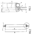
- the walls of the two adjacent tanks of the two electrical panels insulated from the gas are indicated by the references 1 and 2.
- the junction of the invention it is therefore necessary to make circular openings in these walls beforehand, taking into account that the diameter d1 of the opening made in the wall 1 must be slightly less than the diameter d2 of the opening made in the wall 2.
- the junction of the invention is composed of a series of independent elements, clearly illustrated in the exploded view of FIG. 1, and more precisely an annular packing 3 having an inner diameter greater than the diameter d2 defined above; a ring tape 4 covering the lining 3, having an outside diameter greater than said lining; a rigid ring 5 comprising a cylindrical central part 5a with a diameter equal to or slightly less than d2 and which consequently can be inserted without play or very little, between the opening of the wall 2 and the opposite peripheral portions 5b and 5c whose outer diameters are respectively greater than d2 and less than d1; and finally an open flexible ring 6 which is provided with a clamping means 7, preferably with a screw in order to be able to modify the diameter at will.
- the rigid ring 5 has a cylindrical central portion 5a having a height which is calculated as a function of the degree of deformation which we want to impart to the lining 3, once the junction is tightened.
- the part 5a of the ring 5 abuts against the external part of the wall 1 and thus determines the distance between the two walls 1 and 2 and also consequently the space available for the lining 3.
- the peripheral portion 5b is formed by a rib cantilevered at right angles, in order to constitute a stop against the internal part of the wall 2, and consequently determines the mounting position of the ring 5.
- the opposite peripheral portion 5c constitutes finally an anchoring base for the flexible ring 6 and has a concave toroidal shape.
- the rigid ring 5 can be produced in a single piece or in several parts which can be connected to each other in order to form a continuous or even partially discontinuous whole, provided that this discontinuity does not compromise the uniform distribution of the forces on the wall 2 on the one hand and on the flexible ring 6 on the other hand.
- the flexible ring 6 it is preferably constituted by a continuous tube having a circular section, but it is obviously possible to use tubes having different sections, thus varying according to suitability the shape of the base of the ring 6 in position 5c of the rigid ring 5.
- the flexible ring 6 can finally be formed, in a discontinuous manner, by several spherical, cylindrical portions or of any other shape connected together in chain.
- the materials used for the construction of the two rings 5 and 6 described above can be of metallic or plastic nature.
- the choice of one or the other material will be made according to the mechanical characteristics and resistance to corrosion desired.
- non-ferromagnetic metallic materials are preferred, such as aluminum and its alloys.
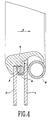
- the assembly and tightening of the junction according to the present invention are particularly simple. In the first place, it is necessary to position the ring 4 and the lining 3 between the walls 1 and 2. Their insertion does not present any particular difficulties, even if their diameter is greater than the openings in which they are inserted. these are elements that easily deform. Thereafter, it is necessary to insert, on the side of the wall 2, the protruding rigid ring 5, since its portion 5C has a diameter less than the two openings and even at the opening 1. The ring should be inserted 5 until its portion 5b abuts against the wall 2, so that its central portion 5a maintains in precise position the gasket 3 of the ring 4 without having to have recourse to fixing devices for these elements temporary, even when walls 1 and 2 are vertical. Indeed, the centering of the lining 3 and of the ring 4 with respect to the openings of the walls 1 and 2 is not of particular importance with regard to gas tightness.
- the flexible ring 6 is wedged on the anchoring portion 5c of the ring 5, which protrudes inside the tank delimited by the wall 1, after having previously loosened the clamping means 7. In this position, the ring 6 does not yet adhere to the bottom of its base in the portion 5c of the ring, but it abuts against the distal part of the latter and, in the opposite part, against the internal surface of the wall 1 (fig. 4).
- the clamping devices 7 - which are for example constituted by a double-threaded screw right / left in order to increase the clamping speed - the diameter of the flexible ring 6 gradually decreases until it enters gradually in its location.
- the entire ring 5 is biased in the direction of arrow F (fig.
- the junction according to the present invention has been described in accordance with a preferred embodiment, but it is clear that there are many other solutions which are all within the reach of a technician working in this field.
- the shape of the peripheral portions of the ring 5 or of the clamping ring 6 can be modified, one or the other being able to be constituted by several united or connected sections.
Landscapes
- Engineering & Computer Science (AREA)
- Power Engineering (AREA)
- Filling Or Discharging Of Gas Storage Vessels (AREA)
- Gasket Seals (AREA)
- Joints Allowing Movement (AREA)
- Gas-Insulated Switchgears (AREA)
- Valve Housings (AREA)
- Driving Mechanisms And Operating Circuits Of Arc-Extinguishing High-Tension Switches (AREA)
Applications Claiming Priority (2)
| Application Number | Priority Date | Filing Date | Title |
|---|---|---|---|
| ITMI941964A IT1271218B (it) | 1994-09-27 | 1994-09-27 | Giunzione a tenuta di gas tra aperture circolari adiacenti di serbatoi di gas a bassa pressione |
| ITMI941964 | 1994-09-27 |
Publications (2)
| Publication Number | Publication Date |
|---|---|
| EP0706248A1 true EP0706248A1 (de) | 1996-04-10 |
| EP0706248B1 EP0706248B1 (de) | 1998-11-04 |
Family
ID=11369603
Family Applications (1)
| Application Number | Title | Priority Date | Filing Date |
|---|---|---|---|
| EP95410097A Expired - Lifetime EP0706248B1 (de) | 1994-09-27 | 1995-09-05 | Gasdichte Verbindung zwischen benachbarten, kreisformigen Öffnungen von Niederdruckgasbehältern |
Country Status (5)
| Country | Link |
|---|---|
| EP (1) | EP0706248B1 (de) |
| CN (1) | CN1045504C (de) |
| DE (1) | DE69505771T2 (de) |
| ES (1) | ES2126236T3 (de) |
| IT (1) | IT1271218B (de) |
Families Citing this family (2)
| Publication number | Priority date | Publication date | Assignee | Title |
|---|---|---|---|---|
| JP2005048790A (ja) * | 2003-07-29 | 2005-02-24 | Tm T & D Kk | 圧力容器 |
| CN112993919A (zh) * | 2019-12-13 | 2021-06-18 | 上海禾赛科技股份有限公司 | 一种激光雷达及其线缆接口件 |
Citations (4)
| Publication number | Priority date | Publication date | Assignee | Title |
|---|---|---|---|---|
| DE7731063U1 (de) * | 1977-10-07 | 1978-02-09 | Fritz Driescher Spezialfabrik Fuer Elektrizitaetswerksbedarf, 5144 Wegberg | Metallgekapselte, isoliergasgefüllte Schaltanlage |
| DE3030021A1 (de) * | 1980-08-08 | 1982-03-25 | Brown, Boveri & Cie Ag, 6800 Mannheim | Vorrichtung zur verbindung zweier rohrleitungen mit kugelfoermigem verbindungselement |
| DE3237852A1 (de) * | 1982-10-13 | 1984-04-19 | Franz-Karl Dipl.-Ing. 4000 Düsseldorf Grossmann | Dichtungs-armatur |
| DE8904074U1 (de) * | 1989-04-03 | 1990-08-09 | Sachsenwerk AG, 8400 Regensburg | Anschlußkasten für Hochspannungsschaltanlagen |
Family Cites Families (1)
| Publication number | Priority date | Publication date | Assignee | Title |
|---|---|---|---|---|
| DE4210773C2 (de) * | 1992-04-01 | 1995-11-02 | Felten & Guilleaume Energie | Metallgekapselte, druckgasisolierte SF¶6¶-Schaltanlage mit einer Sammelschienenanordnung |
-
1994
- 1994-09-27 IT ITMI941964A patent/IT1271218B/it active IP Right Grant
-
1995
- 1995-09-05 ES ES95410097T patent/ES2126236T3/es not_active Expired - Lifetime
- 1995-09-05 DE DE69505771T patent/DE69505771T2/de not_active Expired - Fee Related
- 1995-09-05 EP EP95410097A patent/EP0706248B1/de not_active Expired - Lifetime
- 1995-09-27 CN CN95117386A patent/CN1045504C/zh not_active Expired - Fee Related
Patent Citations (4)
| Publication number | Priority date | Publication date | Assignee | Title |
|---|---|---|---|---|
| DE7731063U1 (de) * | 1977-10-07 | 1978-02-09 | Fritz Driescher Spezialfabrik Fuer Elektrizitaetswerksbedarf, 5144 Wegberg | Metallgekapselte, isoliergasgefüllte Schaltanlage |
| DE3030021A1 (de) * | 1980-08-08 | 1982-03-25 | Brown, Boveri & Cie Ag, 6800 Mannheim | Vorrichtung zur verbindung zweier rohrleitungen mit kugelfoermigem verbindungselement |
| DE3237852A1 (de) * | 1982-10-13 | 1984-04-19 | Franz-Karl Dipl.-Ing. 4000 Düsseldorf Grossmann | Dichtungs-armatur |
| DE8904074U1 (de) * | 1989-04-03 | 1990-08-09 | Sachsenwerk AG, 8400 Regensburg | Anschlußkasten für Hochspannungsschaltanlagen |
Also Published As
| Publication number | Publication date |
|---|---|
| DE69505771T2 (de) | 1999-05-27 |
| DE69505771D1 (de) | 1998-12-10 |
| CN1045504C (zh) | 1999-10-06 |
| ITMI941964A0 (it) | 1994-09-27 |
| IT1271218B (it) | 1997-05-27 |
| CN1131247A (zh) | 1996-09-18 |
| ES2126236T3 (es) | 1999-03-16 |
| ITMI941964A1 (it) | 1996-03-27 |
| EP0706248B1 (de) | 1998-11-04 |
Similar Documents
| Publication | Publication Date | Title |
|---|---|---|
| EP0808008B1 (de) | Abgedichtetes Kabelverbindungsgehäuse | |
| FR2463526A1 (fr) | Connecteur de cable a armure metallique sous gaine | |
| FR2546215A1 (fr) | Traversee pour le passage de conduits tels que des cables, tuyaux, etc. par une ouverture dans le mur et dispositif pour la realisation d'une surface interieure pour une telle traversee dans un mur en beton | |
| EP0942507B1 (de) | Abgedichtetes Gehäuse einer Vorrichtung mit Zugang zu einem Kabel | |
| EP1251617B1 (de) | Kabelabdichtung | |
| FR2740199A1 (fr) | Manchon modulaire pour la protection, la reparation ou la renovation d'une canalisation | |
| EP0346163A1 (de) | Vorrichtung zur Verbindung von Rohren, insbesondere für Gas | |
| EP0653825A1 (de) | Abgedichtete Durchführung mit einer biegsamen Membrane und einem Wegwerfdeckel | |
| FR2723162A1 (fr) | Joint annulaire d'etancheite | |
| EP0706248A1 (de) | Gasdichte Verbindung zwischen benachbarten, kreisformigen Öffnungen von Niederdruckgasbehältern | |
| FR2604238A1 (fr) | Dispositif de prise de branchement sur une canalisation. | |
| EP1251616A1 (de) | Abdichtung für elektrisches Kabel | |
| EP0277898A1 (de) | Gehäuse für Fluidleitungen im Mauerwerk | |
| EP0938759A1 (de) | Hochspannungsanordnung mit trennbaren elementen | |
| FR2862367A1 (fr) | Raccord a sertir a corps conducteur | |
| FR2759762A1 (fr) | Raccord isolant dielectrique et procede d'assemblage d'un tel raccord | |
| EP0350394B1 (de) | Regenwasserabflussanordnung | |
| FR2867251A1 (fr) | Raccord a sertir comprenant une bague de visualisation secable | |
| FR2582383A1 (fr) | Dispositif de surveillance et de signalisation automatiques des fuites de gaz dans un circuit de distribution de gaz | |
| EP0924352B1 (de) | Inspektionskammer für unterirdisches Leitungssystem | |
| FR2800842A1 (fr) | Installation de stockage et de delivrance de gaz | |
| FR2658583A1 (fr) | Dispositif de raccordement et d'etancheite pour deux tuyaux montes bout a bout. | |
| FR2699752A1 (fr) | Dispositif pour traversée étanche de câble, notamment dans une boîte de dérivation électrique de remorque ou de tracteur routier. | |
| FR2817667A1 (fr) | Dispositif de connexion electrique a haute tension | |
| FR2573255A2 (fr) | Traversee etanche de paroi |
Legal Events
| Date | Code | Title | Description |
|---|---|---|---|
| PUAI | Public reference made under article 153(3) epc to a published international application that has entered the european phase |
Free format text: ORIGINAL CODE: 0009012 |
|
| AK | Designated contracting states |
Kind code of ref document: A1 Designated state(s): DE ES FR GB |
|
| 17P | Request for examination filed |
Effective date: 19960924 |
|
| GRAG | Despatch of communication of intention to grant |
Free format text: ORIGINAL CODE: EPIDOS AGRA |
|
| 17Q | First examination report despatched |
Effective date: 19971117 |
|
| GRAG | Despatch of communication of intention to grant |
Free format text: ORIGINAL CODE: EPIDOS AGRA |
|
| GRAH | Despatch of communication of intention to grant a patent |
Free format text: ORIGINAL CODE: EPIDOS IGRA |
|
| GRAH | Despatch of communication of intention to grant a patent |
Free format text: ORIGINAL CODE: EPIDOS IGRA |
|
| GRAA | (expected) grant |
Free format text: ORIGINAL CODE: 0009210 |
|
| AK | Designated contracting states |
Kind code of ref document: B1 Designated state(s): DE ES FR GB |
|
| REF | Corresponds to: |
Ref document number: 69505771 Country of ref document: DE Date of ref document: 19981210 |
|
| GBT | Gb: translation of ep patent filed (gb section 77(6)(a)/1977) |
Effective date: 19990111 |
|
| REG | Reference to a national code |
Ref country code: ES Ref legal event code: FG2A Ref document number: 2126236 Country of ref document: ES Kind code of ref document: T3 |
|
| PLBE | No opposition filed within time limit |
Free format text: ORIGINAL CODE: 0009261 |
|
| STAA | Information on the status of an ep patent application or granted ep patent |
Free format text: STATUS: NO OPPOSITION FILED WITHIN TIME LIMIT |
|
| 26N | No opposition filed | ||
| REG | Reference to a national code |
Ref country code: FR Ref legal event code: CD Ref country code: FR Ref legal event code: CA |
|
| REG | Reference to a national code |
Ref country code: GB Ref legal event code: IF02 |
|
| REG | Reference to a national code |
Ref country code: FR Ref legal event code: CJ Ref country code: FR Ref legal event code: CD |
|
| PGFP | Annual fee paid to national office [announced via postgrant information from national office to epo] |
Ref country code: FR Payment date: 20080904 Year of fee payment: 14 |
|
| PGFP | Annual fee paid to national office [announced via postgrant information from national office to epo] |
Ref country code: GB Payment date: 20080910 Year of fee payment: 14 |
|
| PGFP | Annual fee paid to national office [announced via postgrant information from national office to epo] |
Ref country code: DE Payment date: 20080908 Year of fee payment: 14 |
|
| PGFP | Annual fee paid to national office [announced via postgrant information from national office to epo] |
Ref country code: ES Payment date: 20081021 Year of fee payment: 14 |
|
| GBPC | Gb: european patent ceased through non-payment of renewal fee |
Effective date: 20090905 |
|
| REG | Reference to a national code |
Ref country code: FR Ref legal event code: ST Effective date: 20100531 |
|
| PG25 | Lapsed in a contracting state [announced via postgrant information from national office to epo] |
Ref country code: FR Free format text: LAPSE BECAUSE OF NON-PAYMENT OF DUE FEES Effective date: 20090930 Ref country code: DE Free format text: LAPSE BECAUSE OF NON-PAYMENT OF DUE FEES Effective date: 20100401 |
|
| PG25 | Lapsed in a contracting state [announced via postgrant information from national office to epo] |
Ref country code: GB Free format text: LAPSE BECAUSE OF NON-PAYMENT OF DUE FEES Effective date: 20090905 |
|
| REG | Reference to a national code |
Ref country code: ES Ref legal event code: FD2A Effective date: 20110715 |
|
| PG25 | Lapsed in a contracting state [announced via postgrant information from national office to epo] |
Ref country code: ES Free format text: LAPSE BECAUSE OF NON-PAYMENT OF DUE FEES Effective date: 20110705 |
|
| PG25 | Lapsed in a contracting state [announced via postgrant information from national office to epo] |
Ref country code: ES Free format text: LAPSE BECAUSE OF NON-PAYMENT OF DUE FEES Effective date: 20090906 |