EP0705970A1 - Multi-cylinder internal combustion engine - Google Patents
Multi-cylinder internal combustion engine Download PDFInfo
- Publication number
- EP0705970A1 EP0705970A1 EP95113886A EP95113886A EP0705970A1 EP 0705970 A1 EP0705970 A1 EP 0705970A1 EP 95113886 A EP95113886 A EP 95113886A EP 95113886 A EP95113886 A EP 95113886A EP 0705970 A1 EP0705970 A1 EP 0705970A1
- Authority
- EP
- European Patent Office
- Prior art keywords
- internal combustion
- combustion engine
- manifold
- housing
- engine according
- Prior art date
- Legal status (The legal status is an assumption and is not a legal conclusion. Google has not performed a legal analysis and makes no representation as to the accuracy of the status listed.)
- Granted
Links
Images

Classifications
-
- F—MECHANICAL ENGINEERING; LIGHTING; HEATING; WEAPONS; BLASTING
- F02—COMBUSTION ENGINES; HOT-GAS OR COMBUSTION-PRODUCT ENGINE PLANTS
- F02F—CYLINDERS, PISTONS OR CASINGS, FOR COMBUSTION ENGINES; ARRANGEMENTS OF SEALINGS IN COMBUSTION ENGINES
- F02F7/00—Casings, e.g. crankcases or frames
- F02F7/0002—Cylinder arrangements
- F02F7/0009—Crankcases of opposed piston engines
-
- F—MECHANICAL ENGINEERING; LIGHTING; HEATING; WEAPONS; BLASTING
- F01—MACHINES OR ENGINES IN GENERAL; ENGINE PLANTS IN GENERAL; STEAM ENGINES
- F01N—GAS-FLOW SILENCERS OR EXHAUST APPARATUS FOR MACHINES OR ENGINES IN GENERAL; GAS-FLOW SILENCERS OR EXHAUST APPARATUS FOR INTERNAL COMBUSTION ENGINES
- F01N3/00—Exhaust or silencing apparatus having means for purifying, rendering innocuous, or otherwise treating exhaust
- F01N3/08—Exhaust or silencing apparatus having means for purifying, rendering innocuous, or otherwise treating exhaust for rendering innocuous
- F01N3/10—Exhaust or silencing apparatus having means for purifying, rendering innocuous, or otherwise treating exhaust for rendering innocuous by thermal or catalytic conversion of noxious components of exhaust
- F01N3/24—Exhaust or silencing apparatus having means for purifying, rendering innocuous, or otherwise treating exhaust for rendering innocuous by thermal or catalytic conversion of noxious components of exhaust characterised by constructional aspects of converting apparatus
- F01N3/30—Arrangements for supply of additional air
-
- F—MECHANICAL ENGINEERING; LIGHTING; HEATING; WEAPONS; BLASTING
- F02—COMBUSTION ENGINES; HOT-GAS OR COMBUSTION-PRODUCT ENGINE PLANTS
- F02B—INTERNAL-COMBUSTION PISTON ENGINES; COMBUSTION ENGINES IN GENERAL
- F02B75/00—Other engines
- F02B75/16—Engines characterised by number of cylinders, e.g. single-cylinder engines
- F02B75/18—Multi-cylinder engines
- F02B75/24—Multi-cylinder engines with cylinders arranged oppositely relative to main shaft and of "flat" type
- F02B75/243—Multi-cylinder engines with cylinders arranged oppositely relative to main shaft and of "flat" type with only one crankshaft of the "boxer" type, e.g. all connecting rods attached to separate crankshaft bearings
-
- F—MECHANICAL ENGINEERING; LIGHTING; HEATING; WEAPONS; BLASTING
- F02—COMBUSTION ENGINES; HOT-GAS OR COMBUSTION-PRODUCT ENGINE PLANTS
- F02M—SUPPLYING COMBUSTION ENGINES IN GENERAL WITH COMBUSTIBLE MIXTURES OR CONSTITUENTS THEREOF
- F02M26/00—Engine-pertinent apparatus for adding exhaust gases to combustion-air, main fuel or fuel-air mixture, e.g. by exhaust gas recirculation [EGR] systems
- F02M26/13—Arrangement or layout of EGR passages, e.g. in relation to specific engine parts or for incorporation of accessories
- F02M26/36—Arrangement or layout of EGR passages, e.g. in relation to specific engine parts or for incorporation of accessories with means for adding fluids other than exhaust gas to the recirculation passage; with reformers
-
- F—MECHANICAL ENGINEERING; LIGHTING; HEATING; WEAPONS; BLASTING
- F02—COMBUSTION ENGINES; HOT-GAS OR COMBUSTION-PRODUCT ENGINE PLANTS
- F02M—SUPPLYING COMBUSTION ENGINES IN GENERAL WITH COMBUSTIBLE MIXTURES OR CONSTITUENTS THEREOF
- F02M26/00—Engine-pertinent apparatus for adding exhaust gases to combustion-air, main fuel or fuel-air mixture, e.g. by exhaust gas recirculation [EGR] systems
- F02M26/13—Arrangement or layout of EGR passages, e.g. in relation to specific engine parts or for incorporation of accessories
- F02M26/42—Arrangement or layout of EGR passages, e.g. in relation to specific engine parts or for incorporation of accessories having two or more EGR passages; EGR systems specially adapted for engines having two or more cylinders
-
- F—MECHANICAL ENGINEERING; LIGHTING; HEATING; WEAPONS; BLASTING
- F02—COMBUSTION ENGINES; HOT-GAS OR COMBUSTION-PRODUCT ENGINE PLANTS
- F02B—INTERNAL-COMBUSTION PISTON ENGINES; COMBUSTION ENGINES IN GENERAL
- F02B2275/00—Other engines, components or details, not provided for in other groups of this subclass
- F02B2275/18—DOHC [Double overhead camshaft]
-
- F—MECHANICAL ENGINEERING; LIGHTING; HEATING; WEAPONS; BLASTING
- F02—COMBUSTION ENGINES; HOT-GAS OR COMBUSTION-PRODUCT ENGINE PLANTS
- F02F—CYLINDERS, PISTONS OR CASINGS, FOR COMBUSTION ENGINES; ARRANGEMENTS OF SEALINGS IN COMBUSTION ENGINES
- F02F1/00—Cylinders; Cylinder heads
- F02F1/02—Cylinders; Cylinder heads having cooling means
- F02F1/10—Cylinders; Cylinder heads having cooling means for liquid cooling
- F02F2001/104—Cylinders; Cylinder heads having cooling means for liquid cooling using an open deck, i.e. the water jacket is open at the block top face
-
- F—MECHANICAL ENGINEERING; LIGHTING; HEATING; WEAPONS; BLASTING
- F02—COMBUSTION ENGINES; HOT-GAS OR COMBUSTION-PRODUCT ENGINE PLANTS
- F02F—CYLINDERS, PISTONS OR CASINGS, FOR COMBUSTION ENGINES; ARRANGEMENTS OF SEALINGS IN COMBUSTION ENGINES
- F02F1/00—Cylinders; Cylinder heads
- F02F1/24—Cylinder heads
- F02F2001/244—Arrangement of valve stems in cylinder heads
- F02F2001/245—Arrangement of valve stems in cylinder heads the valve stems being orientated at an angle with the cylinder axis
-
- F—MECHANICAL ENGINEERING; LIGHTING; HEATING; WEAPONS; BLASTING
- F02—COMBUSTION ENGINES; HOT-GAS OR COMBUSTION-PRODUCT ENGINE PLANTS
- F02M—SUPPLYING COMBUSTION ENGINES IN GENERAL WITH COMBUSTIBLE MIXTURES OR CONSTITUENTS THEREOF
- F02M26/00—Engine-pertinent apparatus for adding exhaust gases to combustion-air, main fuel or fuel-air mixture, e.g. by exhaust gas recirculation [EGR] systems
- F02M26/13—Arrangement or layout of EGR passages, e.g. in relation to specific engine parts or for incorporation of accessories
- F02M26/41—Arrangement or layout of EGR passages, e.g. in relation to specific engine parts or for incorporation of accessories characterised by the arrangement of the recirculation passage in relation to the engine, e.g. to cylinder heads, liners, spark plugs or manifolds; characterised by the arrangement of the recirculation passage in relation to specially adapted combustion chambers
-
- Y—GENERAL TAGGING OF NEW TECHNOLOGICAL DEVELOPMENTS; GENERAL TAGGING OF CROSS-SECTIONAL TECHNOLOGIES SPANNING OVER SEVERAL SECTIONS OF THE IPC; TECHNICAL SUBJECTS COVERED BY FORMER USPC CROSS-REFERENCE ART COLLECTIONS [XRACs] AND DIGESTS
- Y02—TECHNOLOGIES OR APPLICATIONS FOR MITIGATION OR ADAPTATION AGAINST CLIMATE CHANGE
- Y02T—CLIMATE CHANGE MITIGATION TECHNOLOGIES RELATED TO TRANSPORTATION
- Y02T10/00—Road transport of goods or passengers
- Y02T10/10—Internal combustion engine [ICE] based vehicles
- Y02T10/12—Improving ICE efficiencies
Definitions
- the invention relates to a multi-cylinder internal combustion engine with an intake and an exhaust system according to the preamble of the main claim.
- Another form of emission improvement or reduction is external exhaust gas recirculation.
- part of the exhaust gas is returned to the intake system of the internal combustion engine.
- the combustion air supplied to the internal combustion engine is mixed with relatively cold exhaust gas, as a result of which the NO x generation is reduced due to the influence of the recirculated exhaust gas.
- Part of the exhaust gas is removed from the exhaust line of the internal combustion engine and fed to the intake system via an exhaust gas recirculation valve.
- the invention has for its object to design an internal combustion engine so that both systems to improve emissions, the secondary air feed and the external exhaust gas recirculation can be operated with the least possible design effort. Both systems for improving emissions should be able to be used with the least amount of wiring.
- the manifold integrated into the housing can be produced particularly easily in terms of production technology if it is embedded in a flange surface of the cylinder head, which is used to connect the exhaust manifold, and if this manifold is covered by a contact surface of the exhaust manifold.
- the manifold is thus to be designed as an upwardly open recess or groove during the manufacture of the cylinder head, and can already be formed when the casting mold is created.
- the only necessary machining of the The manifold is the required machining of the flange surface.
- this manifold is connected to the valves (exhaust gas recirculation valve or secondary air valve) through a connecting channel running between two adjacent cylinder bores in the housing, space-saving integration into the housing also results here.
- This connecting channel can also be produced in a casting mold in a simple manner without machining steps.
- the external installation space required by the valves is kept small if the valves are arranged on a common connection surface on the housing and if there are connections from this connection surface to the manifold and to the intake system.
- the processing effort is also kept small by a common connection surface.
- the internal combustion engine with integrated exhaust gas recirculation and secondary air feed is designed as a two-row internal combustion engine, a merging can be achieved in a simple and cost-effective manner by means of a single connecting line, so that the valve effort is minimized when the channels are largely integrated into the housing.
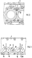
- the internal combustion engine described in more detail below is shown as a boxer engine without restricting the invention to this embodiment.
- the crankcase 1 of the internal combustion engine is in the longitudinal direction divided and consists of two crankcase halves 2, 3 in open-deck design with integrated cylinder liners. These crankcase halves 2, 3 are each covered by a cylinder head 4, in which inlet channels 5 and outlet channels 6 and corresponding inlet valves 7 and outlet valves 8 are integrated.
- the inlet duct 5 is connected to a manifold 11 via a suction pipe 9, into which an injection valve 10 opens. In this manifold 11, the known throttle valve (not shown) for regulating the air supply is formed.
- the outlet channels 6 are connected to exhaust manifolds 12, which are part of the exhaust system, not shown, with an exhaust gas catalytic converter.
- the downwardly open exhaust ports of the cylinders of each of the two rows of cylinders open into a common flange surface 13 on the underside 14 of the cylinder head 4.
- FIG. 3 the respective two exhaust ports 6 of the second and third cylinders of the left row of cylinders (FIG. 1) are shown.
- the flange surface 13 encompasses all the outlet channel openings of the cylinders of a row of cylinders and serves as a connection surface of a corresponding exhaust manifold unit.
- the total of three manifold pipes 15 of the exhaust manifold 12 open into a common flange plate 16 which abuts the flange surface 13.
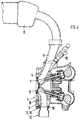
- a recess 17 is embedded in the flange surface 13, which in this exemplary embodiment is formed on the side of the outlet channels 6 facing the crankcase and which extends over almost the entire length of the flange surface 13.
- This depression 17 is covered by the flange plate 16 of the exhaust manifold 12 and, in the closed state, serves as a collecting line 18.
- Secondary channels 19 extend from this collecting line 18, each of which opens into one of the outlet channels 6. In this exemplary embodiment, these secondary channels 19 run in a straight line and are designed as bores.
- a connecting duct 20 extends from the manifold 18 and, in this exemplary embodiment, runs between the second and third cylinders of the left bank of cylinders (FIG. 1) or between the fourth and fifth cylinders of the right bank of cylinders and into one in the cylinder head 4 poured, open to the crankcase recess 21 opens.
- This recess 21 merges into a cast-in housing recess 22 formed in the crankcase 1 or in each of the two crankcase halves 2 or 3. This is open to the connecting surface with the cylinder head 4.
- the connection between the depression 21 and the housing recess 22 is sealed off via the seal, known per se, between the crankcase and the cylinder head.
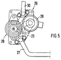
- a valve unit 26 is flanged to the flange surface 24 shown on the left in FIG. 1.
- One end of a connecting line 27 is flanged to the right flange surface 25, the other end of which is connected to the valve unit 26.
- the valve unit 26 is composed of an exhaust gas recirculation valve 28 (EGR valve) and a secondary air valve 29. Both valves are connected in a manner not shown to an engine control unit which switches them in dependence on predetermined operating conditions.
- the secondary air valve 29 can either be connected to a secondary air pump or as a freely suction valve to an air filter unit.
- the exhaust gas recirculation valve 28 is connected to the intake system of the internal combustion engine via a connecting line 30, i.e. there is a connection between the exhaust gas recirculation valve 28 and the manifold 11 with the throttle valve, not shown.
- the exhaust gas recirculation valve 28 and the secondary air valve 29 can - as shown here - be designed as individual valves. However, it is also possible to combine the valve functions in a combination valve.
- the two valves 28, 29 are controlled by the control device such that in the warm-up phase of the engine, fresh air is sucked in or blown in via the opened secondary air valve 29, which directly or via the connecting line 27, the bores 23, the housing recesses 22 or the depressions 21 connected to them reach the collecting lines 18. From these manifolds 18 arrives Fresh air or secondary air via the secondary channels 19 into the outlet channels 6 and can - as described above - lead to faster heating of the downstream catalysts.
- the exhaust gas recirculation valve 28 is closed, so that there is no interference here.
- the secondary air valve 29 is closed, ie the entry of secondary or fresh air is stopped.
- the exhaust gas recirculation valve 28 is opened to a greater or lesser extent, so that part of the exhaust gas flow via the open exhaust gas recirculation valve via the secondary channels 19, the collecting lines 18, the recess 21 and the housing recess 22 as well as the bores 23 and the connecting line 27 28 and the connecting line 30 is passed into the intake tract.
- This partially Recirculation of exhaust gas into the intake tract leads to the previously described and known improvement in the exhaust gas behavior.
Landscapes
- Engineering & Computer Science (AREA)
- Chemical & Material Sciences (AREA)
- Combustion & Propulsion (AREA)
- Mechanical Engineering (AREA)
- General Engineering & Computer Science (AREA)
- Chemical Kinetics & Catalysis (AREA)
- Health & Medical Sciences (AREA)
- Toxicology (AREA)
- Exhaust Gas After Treatment (AREA)
- Cylinder Crankcases Of Internal Combustion Engines (AREA)
- Exhaust-Gas Circulating Devices (AREA)
Abstract
Description
Die Erfindung geht aus von einer mehrzylindrigen Brennkraftmaschine mit einem Ansaug- und einem Abgassystem nach der Gattung des Hauptanspruches.The invention relates to a multi-cylinder internal combustion engine with an intake and an exhaust system according to the preamble of the main claim.
Um mit Brennkraftmaschinen die derzeitigen und zukünftigen gesetzlichen Abgasvorschriften erfüllen zu können, sind zum Teil erhebliche Eingriffe in den Abgasstrang und den Verbrennungsvorgang erforderlich. Zwei bekannte Verfahren zur Verbesserung des Schadstoffgehaltes sind die Sekundärlufteinspeisung und die externe Abgasrückführung.In order to be able to meet the current and future legal exhaust gas regulations with internal combustion engines, considerable interventions in the exhaust gas line and the combustion process are required in some cases. Two known methods for improving the pollutant content are the secondary air feed and the external exhaust gas recirculation.
Aus der US-PS 4 727 717 ist eine Brennkrattmaschine bekannt, bei der in die Auslaßkanäle im Zylinderkopf ausgebildete Sekundärkanäle münden, die mit einer im Gehäuse der Brennkraftmaschine integrierten Sammelleitung verbunden sind. Über diese Sammelleitung und die in die Auslaßkanäle mündenden Sekundärkanäle wird Frischluft in das Abgassystem eingebracht, um eine schnellere Aufheizung eines Abgaskatalysators zu ermöglichen. Dabei werden die aufgrund des fetteren Kraftstoff-Luftgemisches in der Warmlaufphase des Motors stärker vorhandenen Anteile brennbarer Komponenten im Abgas durch Zugabe von Sekundärluft unter Freisetzung von Wärme oxidiert und so zur Beschleunigung der Katalysatoraufheizung verwendet.From US Pat. No. 4,727,717, a internal combustion engine is known, in which secondary channels formed in the outlet channels in the cylinder head open and are connected to a manifold integrated in the housing of the internal combustion engine. Fresh air is introduced into the exhaust system via this manifold and the secondary ducts opening into the outlet ducts in order to enable a faster heating of an exhaust gas catalytic converter. The flammable fuel-air mixture in the warm-up phase of the engine causes more of the combustible components in the exhaust gas to be oxidized by the addition of secondary air, releasing heat, and thus used to accelerate the catalyst heating.
Eine weitere Form der Emissionsverbesserung bzw. -reduzierung ist die externe Abgasrückführung. Dabei wird in Abhängigkeit bestimmter Betriebsbereiche der Brennkraftmaschine ein Teil des Abgases in das Ansaugsystem der Brennkraftmaschine zurückgeführt. Bei dieser externen Abgasrückführung wird der der Brennkraftmaschine zugeführten Verbrennungsluft relativ kaltes Abgas zugemischt, wodurch die NOx-Entstehung aufgrund des Einflusses des rückgeführten Abgases reduziert wird. Dabei wird aus dem Abgasstrang der Brennkraftmaschine ein Teil des Abgases entnommen und über ein Abgasrückführungsventil dem Saugsystem zugeführt. Der Erfindung liegt die Aufgabe zugrunde, eine Brennkraftmaschine so auszubilden, daß beide Systeme der Emissionsverbesserung, die Sekundärlufteinspeisung und die externe Abgasrückführung mit möglichst geringem konstruktiven Aufwand betrieben werden können. Dabei sollen beide Systeme der Emissionsverbesserung mit möglichst geringem Leitungsaufwand nutzbar sein.Another form of emission improvement or reduction is external exhaust gas recirculation. Depending on certain operating ranges of the internal combustion engine, part of the exhaust gas is returned to the intake system of the internal combustion engine. In this external exhaust gas recirculation, the combustion air supplied to the internal combustion engine is mixed with relatively cold exhaust gas, as a result of which the NO x generation is reduced due to the influence of the recirculated exhaust gas. Part of the exhaust gas is removed from the exhaust line of the internal combustion engine and fed to the intake system via an exhaust gas recirculation valve. The invention has for its object to design an internal combustion engine so that both systems to improve emissions, the secondary air feed and the external exhaust gas recirculation can be operated with the least possible design effort. Both systems for improving emissions should be able to be used with the least amount of wiring.
Diese Aufgabe wird erfindungsgemäß mit den kennzeichnenden Merkmalen des Anspruches 1 gelöst. Durch "Doppel"-Nutzung der für eine Sekundärlufteinspeisung in das Abgassystem vorhandenen Sekundärkanäle und der Sammelleitung für die Abgasrückführung in das Ansaugsystem wird der Leitungsaufwand an der Brennkraftmaschine erheblich reduziert. Durch die "Doppel"-Nutzung von Teilen des Sekundärlufteinspeisungssystems wird nicht nur Leitungsweg an sich eingespart, darüber hinaus ist die nahezu vollständige Integration beider emissionsverbessernder Maßnahmen durch Leitungsführung im Motorgehäuse möglich. Die entsprechenden Kanäle können unter Ausnutzung vorhandener Hohlräume oder durch Integration in entsprechend geeignete Gehäusebestandteile ausgebildet werden. Dadurch ist es möglich, auf aufwendige, externe Rohrleitungssysteme zu verzichten. Die in das Gehäuse integrierten Kanäle können dabei ohne wesentlichen Mehraufwand bei der Herstellung des Kurbelgehäuses bzw. des Zylinderkopfes mit erstellt werden. Dabei können diese Kanäle zumindest teilweise in der Gußform unter Verzicht auf spanende Herstellung erstellt werden. Durch die Integration der Kanäle ist weiterhin eine Beeinflussung der Unterbringung von Anbauteilen an das Motorgehäuse ausgeschlossen.This object is achieved with the characterizing features of claim 1. Through "double" use of the secondary channels available for feeding secondary air into the exhaust system and the manifold for exhaust gas recirculation into the intake system, the line effort on the internal combustion engine is considerably reduced. The "double" use of parts of the secondary air feed system not only saves on the cable route itself, it also allows the almost complete integration of both emission-improving measures by routing the cable in the motor housing. The corresponding channels can be formed using existing cavities or by integrating them into suitable housing components. This makes it possible to dispense with complex external piping systems. The channels integrated in the housing can be created without any significant additional effort in the manufacture of the crankcase or the cylinder head. These channels can at least partially be created in the casting mold, without the need for machining. By integrating the ducts, it is also impossible to influence the placement of attachments on the motor housing.
Die in das Gehäuse integrierte Sammelleitung läßt sich fertigungstechnisch besonders einfach ausbilden, wenn sie in eine Flanschfläche des Zylinderkopfes eingelassen wird, die zur Anbindung des Abgaskrümmers dient, und wenn diese Sammelleitung durch eine Anlagefläche des Abgaskrümmers abgedeckt wird. Die Sammelleitung ist somit bei der Herstellung des Zylinderkopfes als nach oben offene Vertiefung bzw. Nut auszubilden, und kann bereits bei der Erstellung der Gußform ausgeformt werden. Die einzig erforderliche spanende Bearbeitung der Sammelleitung ist die unabhängig davon erforderliche Bearbeitung der Flanschfläche.The manifold integrated into the housing can be produced particularly easily in terms of production technology if it is embedded in a flange surface of the cylinder head, which is used to connect the exhaust manifold, and if this manifold is covered by a contact surface of the exhaust manifold. The manifold is thus to be designed as an upwardly open recess or groove during the manufacture of the cylinder head, and can already be formed when the casting mold is created. The only necessary machining of the The manifold is the required machining of the flange surface.
Insbesondere wenn diese Sammelleitung durch einen zwischen zwei benachbarten Zylinderbohrungen im Gehäuse verlaufenden Verbindungskanal mit den Ventilen (Abgasrückführungsventil bzw. Sekundärluftventil) verbunden ist, ergibt sich auch hier eine platzsparende Integration in das Gehäuse. Auch dieser Verbindungskanal kann fertigungstechnisch einfach ohne spanende Fertigungsschritte in einer Gußform hergestellt werden.In particular, if this manifold is connected to the valves (exhaust gas recirculation valve or secondary air valve) through a connecting channel running between two adjacent cylinder bores in the housing, space-saving integration into the housing also results here. This connecting channel can also be produced in a casting mold in a simple manner without machining steps.
Der weitgehende Verzicht auf spanende Bearbeitung und die Integration der Kanäle in das Gehäuse der Brennkraftmaschine wird darüber hinaus auf vorteilhafte Weise erreicht, wenn der im Zylinderkopf ausgebildete Verbindungskanal zur Sammelleitung in eine Gehäuseaussparung im Kurbelgehäuse mündet, die ebenfalls durch Ausbildung der Gußform erstellt werden kann.The extensive elimination of machining and the integration of the channels in the housing of the internal combustion engine is also achieved in an advantageous manner if the connecting channel formed in the cylinder head for the manifold leads into a housing recess in the crankcase, which can also be created by forming the casting mold.
Die spanlose Herstellung dieser Gehäuseaussparung im Kurbelgehäuse wird erleichtert, wenn diese zum Zylinderkopf hin offen ist, so daß die Verbindung zwischen dem Verbindungskanal im Zylinderkopf und der Gehäuseaussparung im Kurbelgehäuse in der Flanschfläche zwischen den beiden Bauteilen liegt. Die Abdichtung der Verbindung erfolgt dann durch die übliche Abdichtung zwischen Kurbelgehäuse und Zylinderkopf.The chipless production of this housing recess in the crankcase is facilitated if it is open towards the cylinder head, so that the connection between the connecting channel in the cylinder head and the housing recess in the crankcase lies in the flange surface between the two components. The connection is then sealed by the usual seal between the crankcase and the cylinder head.
Durch Anbau des Abgasrückfühtungsventils und des Sekundärluftventils an die Außenseite des Gehäuses der Brennkraftmaschine können kompakte Abmessungen und einfacher konstruktiver Aufbau des Gehäuses in einem sinnvollen Kompromiß ermöglicht werden. Die externe Unterbringung der beiden Ventile nimmt im Vergleich zu zwei separaten und externen Gesamtsystemen einen relativ geringen Bauraum in Anspruch. Eine interne Unterbringung würde jedoch erheblichen konstruktiven Mehraufwand bedeuten, der zu einer wesentlichen Verteuerung der Herstellungsverfahren und zu Problemen hinsichtlich der Steifigkeit bzw. der Gewichtsoptimierung führen würde.By fitting the exhaust gas recirculation valve and the secondary air valve to the outside of the housing of the internal combustion engine, compact dimensions and a simple construction of the housing can be made in a sensible compromise. The external placement of the two valves takes up a relatively small amount of space compared to two separate and external overall systems. However, an internal placement would mean considerable additional design effort, which would lead to a significant increase in the cost of the manufacturing process and to problems with regard to rigidity and weight optimization.
Der von den Ventilen benötigte externe Bauraum wird klein gehalten, wenn die Ventile an einer gemeinsamen Anschlußfläche am Gehäuse angeordnet sind und wenn von dieser Anschlußfläche Verbindungen zur Sammelleitung und zum Ansaugsystem bestehen. Durch eine gemeinsame Anschlußfläche wird darüber hinaus der Bearbeitungsaufwand klein gehalten.The external installation space required by the valves is kept small if the valves are arranged on a common connection surface on the housing and if there are connections from this connection surface to the manifold and to the intake system. The processing effort is also kept small by a common connection surface.
Wird die Brennkraftmaschine mit integrierter Abgasrückführung und Sekundärlufteinspeisung als zweireihige Brennkraftmaschine ausgebildet, kann durch eine einzige Verbindungsleitung auf einfache und kostengünstige Weise eine Zusammenführung erreicht werden, so daß bei weitgehender Integration der Kanäle in das Gehäuse der Ventilaufwand minimiert wird.If the internal combustion engine with integrated exhaust gas recirculation and secondary air feed is designed as a two-row internal combustion engine, a merging can be achieved in a simple and cost-effective manner by means of a single connecting line, so that the valve effort is minimized when the channels are largely integrated into the housing.
Weitere Vorteile der Erfindung und vorteilhafte Weiterbildungen ergeben sich aus den Unteransprüchen und der Beschreibung.Further advantages of the invention and advantageous developments emerge from the subclaims and the description.
Ein Ausführungsbeispiel der Erfindung ist in der nachfolgenden Beschreibung und Zeichnung näher erläutert. Letztere zeigt in
- Fig. 1
- einen Querschnitt durch ein Kurbelgehäuse mit angeflanschten Zylinderköpfen eines Boxermotors,
- Fig. 2
- eine nur teilweise dargestellte Ansicht der Flanschfläche des Kurbelgehäuses zum Zylinderkopf,
- Fig. 3
- eine Ansicht der Anschlußfläche der Abgaskrümmer an den Zylinderkopf,
- Fig. 4
- einen Querschnitt durch einen Zylinderkopf mit Teilen der Ansauganlage,
- Fig. 5
- eine Ansicht der Anschlußfläche für das Abgasrückführungs- bzw. Sekundärluftventil.
- Fig. 1
- 3 shows a cross section through a crankcase with flanged cylinder heads of a boxer engine,
- Fig. 2
- a view of the flange surface of the crankcase to the cylinder head only partially shown,
- Fig. 3
- a view of the connection surface of the exhaust manifold to the cylinder head,
- Fig. 4
- a cross section through a cylinder head with parts of the intake system,
- Fig. 5
- a view of the pad for the exhaust gas recirculation or secondary air valve.
Die im nachfolgenden näher beschriebene Brennkraftmaschine ist ohne Beschränkung der Erfindung auf diese Ausführungsform als Boxermotor dargestellt. Das Kurbelgehäuse 1 der Brennkraftmaschine ist in Längsrichtung geteilt und besteht aus zwei Kurbelgehäusehälften 2, 3 in Open-Deck-Bauweise mit integrierten Zylinderbüchsen. Diese Kurbelgehäusehälften 2, 3 werden jeweils durch einen Zylinderkopf 4 abgedeckt, in dem Einlaßkanäle 5 und Auslaßkanäle 6 sowie entsprechende Einlaßventile 7 bzw. Auslaßventile 8 integriert sind. Der Einlaßkanal 5 ist über ein Saugrohr 9, in den ein Einspritzventil 10 mündet, mit einem Sammelrohr 11 verbunden. In diesem Sammelrohr 11 ist die nicht näher dargestellte, an sich bekannte Drosselklappe zur Regelung der Luftzufuhr ausgebildet. Die Auslaßkanäle 6 sind mit Abgaskrümmern 12 verbunden, die Teil der nicht näher dargestellten Abgasanlage mit Abgaskatalysator sind.The internal combustion engine described in more detail below is shown as a boxer engine without restricting the invention to this embodiment. The crankcase 1 of the internal combustion engine is in the longitudinal direction divided and consists of two
Die nach unten offenen Auslaßkanäle der Zylinder jeder der beiden Zylinderreihen münden in eine gemeinsame Flanschfläche 13 an der Unterseite 14 des Zylinderkopfes 4. In Fig. 3 sind die jeweils zwei Auslaßkanäle 6 des zweiten und dritten Zylinders der linken Zylinderreihe (Fig. 1) dargestellt. Die Flanschfläche 13 umfaßt sämtliche Auslaßkanalöffnungen der Zylinder einer Zylinderreihe und dient als Anschlußfläche einer entsprechenden Abgaskrümmereinheit. Die insgesamt drei Krümmerrohre 15 des Abgaskrümmers 12 münden in eine gemeinsame Flanschplatte 16, die an der Flanschfläche 13 anliegt. In die Flanschfläche 13 ist eine Vertiefung 17 eingelassen, die in diesem Ausführungsbeispiel auf der Kurbelgehäuse zugewandten Seite der Auslaßkanäle 6 ausgebildet ist und die sich über nahezu die gesamte Länge der Flanschfläche 13 erstreckt. Diese Vertiefung 17 wird durch die Flanschplatte 16 des Abgaskrümmers 12 abgedeckt und dient im geschlossenen Zustand als Sammelleitung 18. Von dieser Sammelleitung 18 gehen Sekundärkanäle 19 aus, die jeweils in einen der Auslaßkanäle 6 münden. Diese Sekundärkanäle 19 verlaufen in diesem Ausführungsbeispiel geradlinig und sind als Bohrungen ausgeführt.The downwardly open exhaust ports of the cylinders of each of the two rows of cylinders open into a
Von der Sammelleitung 18 geht ein Verbindungskanal 20 aus, der - in diesem Ausführungsbeispiel - zwischen dem zweiten und dritten Zylinder der linken Zylinderreihe (Fig. 1) bzw. zwischen dem vierten und fünften Zylinder der rechten Zylinderreihe verläuft und der in eine in den Zylinderkopf 4 eingegossene, zum Kurbelgehäuse hin offene Vertiefung 21 mündet. Diese Vertiefung 21 geht über in eine im Kurbelgehäuse 1 bzw. in jeder der beiden Kurbelgehäusehälften 2 bzw. 3 ausgebildete, eingegossene Gehäuseaussparung 22. Diese ist zur Verbindungsfläche mit dem Zylinderkopf 4 offen. In zusammengebautem Zustand der Brennkraftmaschine wird die Verbindung zwischen der Vertiefung 21 und der Gehäuseaussparung 22 über die an sich bekannte Abdichtung zwischen Kurbelgehäuse und Zylinderkopf abgedichtet. In jede der beiden Gehäuseaussparungen 22 mündet eine das Kurbelgehäuse durchdringende Bohrung 23, die jeweils von einer Flanschfläche 24, 25 ausgeht. An die in Fig. 1 auf der linken Seite dargestellte Flanschfläche 24 ist eine Ventileinheit 26 angeflanscht. An die rechte Flanschfläche 25 ist das eine Ende einer Verbindungsleitung 27 angeflanscht, deren anderes Ende mit der Ventileinheit 26 verbunden ist.A connecting
Die Ventileinheit 26 setzt sich aus einem Abgasrückführungsventil 28 (AGR-Ventil) und einem Sekundärluftventil 29 zusammen. Beide Ventile sind auf nicht dargestellte Weise mit einem Motorsteuergerät verbunden, das diese in Abhängigkeit vorgegebener Betriebsbedingungen schaltet. Das Sekundärluftventil 29 kann dabei entweder mit einer Sekundärluftpumpe oder als frei saugendes Ventil mit einer Luftfiltereinheit verbunden sein. Das Abgasrückführungsventil 28 ist über eine Verbindungsleitung 30 mit der Sauganlage der Brennkraftmaschine verbunden, d.h. es besteht eine Verbindung zwischen dem Abgasrückführungsventil 28 und dem Sammelrohr 11 mit der nicht dargestellten Drosselklappe. Das Abgasrückführungsventil 28 und das Sekundärluftventil 29 können - wie hier dargestellt - als Einzelventile ausgebildet werden. Es ist jedoch auch möglich, die Ventilfunktionen in einem Kombiventil zu vereinen.The
Im Betrieb der Brennkraftmaschine werden die beiden Ventile 28, 29 vom Steuergerät so angesteuert, daß in der Warmlaufphase des Motors über das geöffnete Sekundärluftventil 29 Frischluft angesaugt bzw. eingeblasen wird, die direkt bzw. über die Verbindungsleitung 27, die Bohrungen 23, die Gehäuseaussparungen 22 bzw. die mit ihnen verbundenen Vertiefungen 21 in die Sammelleitungen 18 gelangt. Von diesen Sammelleitungen 18 gelangt die Frischluft bzw. Sekundärluft über die Sekundärkanäle 19 in die Auslaßkanäle 6 und kann somit - wie zuvor beschrieben - zu einer schnelleren Aufheizung der nachgeschalteten Katalysatoren führen. Während der Warmlaufphase ist das Abgasrückführungsventil 28 verschlossen, so daß hier keine Beeinflussung erfolgt. Nach der Warmlaufphase wird das Sekundärluftventil 29 geschlossen, d.h. der Eintrag von Sekundär- bzw. Frischluft wird gestoppt. In Abhängigkeit vom Betriebszustand des Motors wird das Abgasrückführungsventil 28 mehr oder weniger weit geöffnet, so daß über die Sekundärkanäle 19, die Sammelleitungen 18, die Vertiefung 21 und die Gehäuseaussparung 22 sowie die Bohrungen 23 und die Verbindungsleitung 27 ein Teil des Abgasstromes über das geöffnete Abgasrückführungsventil 28 und die Verbindungsleitung 30 in den Ansaugtrakt geleitet wird. Diese teilweise
Rückführung von Abgas in den Ansaugtrakt führt zu der zuvor beschriebenen und an sich bekannten Verbesserung des Abgasverhaltens.During operation of the internal combustion engine, the two
Recirculation of exhaust gas into the intake tract leads to the previously described and known improvement in the exhaust gas behavior.
Claims (10)
Applications Claiming Priority (2)
| Application Number | Priority Date | Filing Date | Title |
|---|---|---|---|
| DE4435555A DE4435555C1 (en) | 1994-10-05 | 1994-10-05 | Multi-cylinder internal combustion engine |
| DE4435555 | 1994-10-05 |
Publications (2)
| Publication Number | Publication Date |
|---|---|
| EP0705970A1 true EP0705970A1 (en) | 1996-04-10 |
| EP0705970B1 EP0705970B1 (en) | 2000-06-07 |
Family
ID=6529994
Family Applications (1)
| Application Number | Title | Priority Date | Filing Date |
|---|---|---|---|
| EP95113886A Expired - Lifetime EP0705970B1 (en) | 1994-10-05 | 1995-09-05 | Multi-cylinder internal combustion engine |
Country Status (4)
| Country | Link |
|---|---|
| US (1) | US5640848A (en) |
| EP (1) | EP0705970B1 (en) |
| JP (1) | JPH08193543A (en) |
| DE (2) | DE4435555C1 (en) |
Cited By (3)
| Publication number | Priority date | Publication date | Assignee | Title |
|---|---|---|---|---|
| DE10251359A1 (en) * | 2002-11-05 | 2004-05-19 | Daimlerchrysler Ag | Cylinder head for internal combustion engine has casting core with longitudinal channel in shape of wave pre-cast below or above gas exchange channels within cylinder head directly on inner side of flange surface |
| DE10257064A1 (en) * | 2002-12-06 | 2004-06-24 | Bayerische Motoren Werke Ag | Liquid-cooled, cast cylinder head of a multi-cylinder internal combustion engine |
| CN103154486A (en) * | 2010-10-14 | 2013-06-12 | 戴姆勒股份公司 | Combustion engine and a method for producing such a combustion engine |
Families Citing this family (9)
| Publication number | Priority date | Publication date | Assignee | Title |
|---|---|---|---|---|
| DE19621530C1 (en) * | 1996-05-29 | 1997-06-05 | Daimler Benz Ag | Method of reducing harmful emissions from multicylinder combustion engines |
| DE19757931A1 (en) * | 1997-12-24 | 1999-07-01 | Mannesmann Vdo Ag | Device for recirculating exhaust gas and for preheating an exhaust gas cleaner |
| DE19902678C2 (en) * | 1999-01-23 | 2001-11-15 | Audi Ag | Multi-cylinder internal combustion engine |
| DE19937781A1 (en) * | 1999-08-10 | 2001-02-15 | Mann & Hummel Filter | Internal combustion engine with secondary air intake system |
| DE19959138B4 (en) * | 1999-12-08 | 2014-04-03 | Volkswagen Ag | Device for exhaust gas recirculation on an internal combustion engine |
| JP2006219984A (en) * | 2005-02-08 | 2006-08-24 | Nissan Motor Co Ltd | Exhaust system for multiple cylinder internal combustion engine |
| DE102005049462A1 (en) * | 2005-10-15 | 2007-05-03 | Daimlerchrysler Ag | Modern internal combustion engine, has exhaust gas return path for refeeding exhaust gas to intake side of engine, where part of exhaust gas return path is integrated in control housing cover of engine |
| JP4788531B2 (en) * | 2006-09-01 | 2011-10-05 | 日産自動車株式会社 | Engine control device |
| JP2010096076A (en) * | 2008-10-16 | 2010-04-30 | Daihatsu Motor Co Ltd | Exhaust gas recirculation device of internal combustion engine |
Citations (5)
| Publication number | Priority date | Publication date | Assignee | Title |
|---|---|---|---|---|
| US4269029A (en) * | 1978-03-23 | 1981-05-26 | Fiat Auto S.P.A. | Internal combustion engine with exhaust emission control system |
| JPS5929738A (en) * | 1982-08-11 | 1984-02-17 | Tokyo Roki Kk | Exhaust gas purifying device |
| US4727717A (en) | 1980-12-03 | 1988-03-01 | Honda Giken Kogyo Kabushiki Kaisha | Exhaust gas cleaning system for multi-cylinder internal combustion engines |
| FR2655382A1 (en) * | 1989-12-04 | 1991-06-07 | Peugeot | Device for introducing additional gas, such as air, into an internal combustion engine, and engine equipped with such a device |
| FR2696787A1 (en) * | 1992-10-09 | 1994-04-15 | Renault | Additional gas injector for internal combustion engine - includes system for introduction of pressurised air into exhaust from injection manifold, and system for recirculation of exhaust gases back to inlet |
Family Cites Families (5)
| Publication number | Priority date | Publication date | Assignee | Title |
|---|---|---|---|---|
| JPS549651B2 (en) * | 1974-12-28 | 1979-04-26 | ||
| JPS5273231A (en) * | 1975-12-17 | 1977-06-18 | Toyota Motor Corp | Internal combustion engines for vehicles |
| JPS5337232A (en) * | 1976-09-17 | 1978-04-06 | Toyota Motor Corp | Recirculating device of exhaust gas for internal combustion engine |
| JPS618202Y2 (en) * | 1979-07-30 | 1986-03-13 | ||
| US4492209A (en) * | 1981-06-05 | 1985-01-08 | Honda Giken Kogyo Kabushiki Kaisha | Exhaust gas recirculation system |
-
1994
- 1994-10-05 DE DE4435555A patent/DE4435555C1/en not_active Expired - Lifetime
-
1995
- 1995-09-05 DE DE59508450T patent/DE59508450D1/en not_active Expired - Lifetime
- 1995-09-05 EP EP95113886A patent/EP0705970B1/en not_active Expired - Lifetime
- 1995-09-28 US US08/535,824 patent/US5640848A/en not_active Expired - Lifetime
- 1995-10-04 JP JP7257812A patent/JPH08193543A/en active Pending
Patent Citations (5)
| Publication number | Priority date | Publication date | Assignee | Title |
|---|---|---|---|---|
| US4269029A (en) * | 1978-03-23 | 1981-05-26 | Fiat Auto S.P.A. | Internal combustion engine with exhaust emission control system |
| US4727717A (en) | 1980-12-03 | 1988-03-01 | Honda Giken Kogyo Kabushiki Kaisha | Exhaust gas cleaning system for multi-cylinder internal combustion engines |
| JPS5929738A (en) * | 1982-08-11 | 1984-02-17 | Tokyo Roki Kk | Exhaust gas purifying device |
| FR2655382A1 (en) * | 1989-12-04 | 1991-06-07 | Peugeot | Device for introducing additional gas, such as air, into an internal combustion engine, and engine equipped with such a device |
| FR2696787A1 (en) * | 1992-10-09 | 1994-04-15 | Renault | Additional gas injector for internal combustion engine - includes system for introduction of pressurised air into exhaust from injection manifold, and system for recirculation of exhaust gases back to inlet |
Non-Patent Citations (1)
| Title |
|---|
| PATENT ABSTRACTS OF JAPAN vol. 8, no. 124 (M - 301) 9 June 1984 (1984-06-09) * |
Cited By (5)
| Publication number | Priority date | Publication date | Assignee | Title |
|---|---|---|---|---|
| DE10251359A1 (en) * | 2002-11-05 | 2004-05-19 | Daimlerchrysler Ag | Cylinder head for internal combustion engine has casting core with longitudinal channel in shape of wave pre-cast below or above gas exchange channels within cylinder head directly on inner side of flange surface |
| DE10251359B4 (en) * | 2002-11-05 | 2005-01-20 | Daimlerchrysler Ag | Cylinder head of a multi-cylinder internal combustion engine |
| DE10257064A1 (en) * | 2002-12-06 | 2004-06-24 | Bayerische Motoren Werke Ag | Liquid-cooled, cast cylinder head of a multi-cylinder internal combustion engine |
| CN103154486A (en) * | 2010-10-14 | 2013-06-12 | 戴姆勒股份公司 | Combustion engine and a method for producing such a combustion engine |
| CN103154486B (en) * | 2010-10-14 | 2015-07-01 | 戴姆勒股份公司 | Combustion engine and a method for producing such a combustion engine |
Also Published As
| Publication number | Publication date |
|---|---|
| DE59508450D1 (en) | 2000-07-13 |
| US5640848A (en) | 1997-06-24 |
| DE4435555C1 (en) | 1996-03-14 |
| JPH08193543A (en) | 1996-07-30 |
| EP0705970B1 (en) | 2000-06-07 |
Similar Documents
| Publication | Publication Date | Title |
|---|---|---|
| DE60111744T2 (en) | INTERNAL COMBUSTION ENGINE WITH EXHAUST GAS RECYCLING | |
| EP1065350B1 (en) | Combustion engine with a breather device | |
| DE2353908C3 (en) | Multi-cylinder internal combustion engine | |
| DE2353925C3 (en) | Device for monitoring and controlling contamination in an internal combustion engine | |
| DE19531875C1 (en) | Cylinder head for liquid cooled multicylinder combustion engine | |
| DE60109845T2 (en) | Method and device for exhaust ventilation of an internal combustion engine | |
| EP1660771A1 (en) | Air-intake duct system for a combustion engine | |
| EP0705970B1 (en) | Multi-cylinder internal combustion engine | |
| DE4410686C2 (en) | Intake system for internal combustion engines | |
| DE3139309A1 (en) | Internal combustion engine | |
| EP1059435B1 (en) | Arrangement of intake air conduits for a combustion engine | |
| EP0251159B1 (en) | Return line for leak gas from a crank case | |
| EP0405566A1 (en) | Guiding gases in a common cylinderhead for an internal combustion engine | |
| DE19941863A1 (en) | Induction system for internal combustion engine has inlet channels in turbulence valve unit main body, turbulence valve in one channel, container chamber in main body, vacuum channel | |
| EP0104524B1 (en) | Device for the recirculation of exhaust gas in an internal-combustion engine | |
| EP0855502B1 (en) | Internal combustion engine with exhaust gas recirculation device | |
| DE10028131C1 (en) | Exhaust gas feedback system for internal combustion engine has flange component provided with exhaust gas feedback channels leading to exhaust gas feedback line and flow control valve | |
| DE60033057T2 (en) | INTEGRATED AIR FUEL MODULE WITH LOW FUEL GAS EMISSIONS | |
| EP0974748B1 (en) | Reciprocating piston engine with exhaust gas recirculation | |
| DE102016010267B4 (en) | Exhaust device for an engine | |
| DE2617245C2 (en) | Exhaust gas cleaning system for a four-stroke internal combustion engine | |
| EP1825118B1 (en) | Controlling exhaust gas recirculation by means of a load signal on an in-line injection pump | |
| DE3923924C2 (en) | Control device for the intake manifold system of a vehicle internal combustion engine | |
| DE19811782A1 (en) | Internal combustion engine with two exhaust gas superchargers | |
| DE102004032144B4 (en) | Internal combustion engine |
Legal Events
| Date | Code | Title | Description |
|---|---|---|---|
| PUAI | Public reference made under article 153(3) epc to a published international application that has entered the european phase |
Free format text: ORIGINAL CODE: 0009012 |
|
| AK | Designated contracting states |
Kind code of ref document: A1 Designated state(s): DE FR GB IT SE |
|
| 17P | Request for examination filed |
Effective date: 19960905 |
|
| 17Q | First examination report despatched |
Effective date: 19980807 |
|
| GRAG | Despatch of communication of intention to grant |
Free format text: ORIGINAL CODE: EPIDOS AGRA |
|
| GRAG | Despatch of communication of intention to grant |
Free format text: ORIGINAL CODE: EPIDOS AGRA |
|
| GRAH | Despatch of communication of intention to grant a patent |
Free format text: ORIGINAL CODE: EPIDOS IGRA |
|
| GRAH | Despatch of communication of intention to grant a patent |
Free format text: ORIGINAL CODE: EPIDOS IGRA |
|
| ITF | It: translation for a ep patent filed |
Owner name: DE DOMINICIS & MAYER S.R.L. |
|
| GRAG | Despatch of communication of intention to grant |
Free format text: ORIGINAL CODE: EPIDOS AGRA |
|
| GRAA | (expected) grant |
Free format text: ORIGINAL CODE: 0009210 |
|
| AK | Designated contracting states |
Kind code of ref document: B1 Designated state(s): DE FR GB IT SE |
|
| REF | Corresponds to: |
Ref document number: 59508450 Country of ref document: DE Date of ref document: 20000713 |
|
| ET | Fr: translation filed | ||
| GBT | Gb: translation of ep patent filed (gb section 77(6)(a)/1977) |
Effective date: 20000717 |
|
| PLBE | No opposition filed within time limit |
Free format text: ORIGINAL CODE: 0009261 |
|
| STAA | Information on the status of an ep patent application or granted ep patent |
Free format text: STATUS: NO OPPOSITION FILED WITHIN TIME LIMIT |
|
| 26N | No opposition filed | ||
| REG | Reference to a national code |
Ref country code: GB Ref legal event code: IF02 |
|
| REG | Reference to a national code |
Ref country code: FR Ref legal event code: TP |
|
| REG | Reference to a national code |
Ref country code: FR Ref legal event code: CD |
|
| REG | Reference to a national code |
Ref country code: FR Ref legal event code: TP |
|
| REG | Reference to a national code |
Ref country code: GB Ref legal event code: 732E Free format text: REGISTERED BETWEEN 20110310 AND 20110316 |
|
| REG | Reference to a national code |
Ref country code: GB Ref legal event code: 732E Free format text: REGISTERED BETWEEN 20110331 AND 20110406 |
|
| PGFP | Annual fee paid to national office [announced via postgrant information from national office to epo] |
Ref country code: DE Payment date: 20140815 Year of fee payment: 20 |
|
| PGFP | Annual fee paid to national office [announced via postgrant information from national office to epo] |
Ref country code: FR Payment date: 20140919 Year of fee payment: 20 Ref country code: GB Payment date: 20140919 Year of fee payment: 20 Ref country code: SE Payment date: 20140918 Year of fee payment: 20 |
|
| PGFP | Annual fee paid to national office [announced via postgrant information from national office to epo] |
Ref country code: IT Payment date: 20140929 Year of fee payment: 20 |
|
| REG | Reference to a national code |
Ref country code: DE Ref legal event code: R071 Ref document number: 59508450 Country of ref document: DE |
|
| REG | Reference to a national code |
Ref country code: GB Ref legal event code: PE20 Expiry date: 20150904 |
|
| PG25 | Lapsed in a contracting state [announced via postgrant information from national office to epo] |
Ref country code: GB Free format text: LAPSE BECAUSE OF EXPIRATION OF PROTECTION Effective date: 20150904 |
|
| REG | Reference to a national code |
Ref country code: SE Ref legal event code: EUG |