EP0705656A2 - Scarfing method and apparatus - Google Patents
Scarfing method and apparatus Download PDFInfo
- Publication number
- EP0705656A2 EP0705656A2 EP95119086A EP95119086A EP0705656A2 EP 0705656 A2 EP0705656 A2 EP 0705656A2 EP 95119086 A EP95119086 A EP 95119086A EP 95119086 A EP95119086 A EP 95119086A EP 0705656 A2 EP0705656 A2 EP 0705656A2
- Authority
- EP
- European Patent Office
- Prior art keywords
- scarfing
- insert
- oxygen
- workpiece
- stream
- Prior art date
- Legal status (The legal status is an assumption and is not a legal conclusion. Google has not performed a legal analysis and makes no representation as to the accuracy of the status listed.)
- Granted
Links
Images


Classifications
-
- B—PERFORMING OPERATIONS; TRANSPORTING
- B23—MACHINE TOOLS; METAL-WORKING NOT OTHERWISE PROVIDED FOR
- B23K—SOLDERING OR UNSOLDERING; WELDING; CLADDING OR PLATING BY SOLDERING OR WELDING; CUTTING BY APPLYING HEAT LOCALLY, e.g. FLAME CUTTING; WORKING BY LASER BEAM
- B23K7/00—Cutting, scarfing, or desurfacing by applying flames
- B23K7/06—Machines, apparatus, or equipment specially designed for scarfing or desurfacing
-
- B—PERFORMING OPERATIONS; TRANSPORTING
- B23—MACHINE TOOLS; METAL-WORKING NOT OTHERWISE PROVIDED FOR
- B23K—SOLDERING OR UNSOLDERING; WELDING; CLADDING OR PLATING BY SOLDERING OR WELDING; CUTTING BY APPLYING HEAT LOCALLY, e.g. FLAME CUTTING; WORKING BY LASER BEAM
- B23K7/00—Cutting, scarfing, or desurfacing by applying flames
- B23K7/08—Cutting, scarfing, or desurfacing by applying flames by applying additional compounds or means favouring the cutting, scarfing, or desurfacing procedure
-
- F—MECHANICAL ENGINEERING; LIGHTING; HEATING; WEAPONS; BLASTING
- F23—COMBUSTION APPARATUS; COMBUSTION PROCESSES
- F23D—BURNERS
- F23D14/00—Burners for combustion of a gas, e.g. of a gas stored under pressure as a liquid
- F23D14/46—Details, e.g. noise reduction means
- F23D14/48—Nozzles
- F23D14/56—Nozzles for spreading the flame over an area, e.g. for desurfacing of solid material, for surface hardening, or for heating workpieces
Definitions
- This invention relates to a method and apparatus for thermochemically scarfing a metal workpiece and which allows a significant diagonal stand-off distance from the end of the workpiece during preheating and scarfing initiation so that molten metal is not blown onto the scarfing apparatus.
- One conventional scarfing apparatus includes top, side and bottom scarfing units that are mounted across the width and end portions of a support. The top, side and bottom units are arranged to scarf all sides of the slab.
- Both top, side, and bottom units include a manifold and head assembly, which receives and distributes oxygen and fuel gas to upper and lower preheat blocks.
- the upper and lower preheat blocks are spaced from each other to define between the two blocks an oxygen scarfing slot through which a quantity of oxygen is blown onto the slab surface to enable scarfing.
- the lower preheat block includes a fuel gas channel having a discharge end positioned adjacent the oxygen slot for discharging a fuel gas adjacent the oxygen flow.
- the upper preheat block typically is a one-piece unit that includes oxygen and fuel gas channels each having discharge orifices to define nozzles through which a combination of oxygen and fuel gas is discharged for preheating the slab before scarfing. Later, a postmix flow of oxygen and fuel gas provides for scarfing. To maintain a proper vertical stand-off distance of the nozzle exit from the steel slab, the top and bottom scarfing units include riding shoes positioned on respective lower preheat blocks.
- the integrally formed nozzles do not provide for a high speed gas flow outward from the scarfing units, the total diagonal stand-off distance, i.e., the vertical stand-off distance and horizontal stand-off distance (the lead distance from the scarfing unit to the slab) is small, and the scarfing units must be placed in close proximity to the slab during preheating.
- the upper preheat block extends forward and hangs over the lower preheat block to direct the preheating stream of gas discharged from the upper preheat block onto the slab during preheating.
- the molten steel formed on the slab edge may drip onto portions of the upper preheat block positioned below the slab.
- the molten steel may damage the upper preheat block requiring reconstruction or replacement of the preheat blocks.
- the scarfing units are positioned adjacent the slab and heat the slab one to two inches inward of the end to prevent steel and slag from dripping onto the forwardly extending preheat block.
- the one or two inches of unscarfed steel must be either scrapped or hand scarfed, leading to excessive production costs.
- the discharge ends forming the upper preheat nozzles may wear. Because the preheat nozzles are integrally formed in the upper preheat block, any damage to the nozzle area mandates either replacement of the entire upper preheat block, or removal of the damaged area and the brazing of new material onto the upper preheat block.
- thermochemically scarfing a metal workpiece which includes the step of preheating an area on the surface of a stationary workpiece.
- This preheating step includes directing a preheating gas stream toward the area, and the preheating gas stream comprises a high speed central stream of oxidizing gas and a concentric stream of fuel gas coaxially about the central stream so as to be essentially parallel to the flow of the central stream.
- the momentum of the central stream is substantially maintained.
- a stream of scarfing oxidizing gas is directed at an acute angle toward the preheated area of the workpiece, and relative movement is initiated between the workpiece and the stream of scarfing oxidizing gas so as to produce a scarfing cut.
- the preheating gas stream is stabilized, by directing a first stabilizing stream of oxidizing gas immediately above the preheating gas stream, and directing a second stabilizing stream of oxidizing gas immediately below the preheating stream.
- the second stabilizing stream is discharged from the same port which later discharges the scarfing oxidizing gas.
- the apparatus of the present invention comprises a manifold and head assembly which includes upper and lower preheat blocks, with the blocks being spaced from each other to define an oxygen scarfing slot therebetween.
- a plurality of discharge nozzles are mounted adjacent to each other in a row above and parallel to the slot, with each nozzle including a central bore for receiving an oxidizing gas from the manifold and head assembly and discharging the same as the high speed central stream.
- Outer channel means is also provided for receiving a fuel gas from the manifold and head assembly and discharging the same in a substantially concentric stream disposed coaxially about and parallel to the central stream of oxidizing gas.
- the method includes the steps of positioning the manifold and head assembly at a diagonal standoff distance from an end of an elongate metal workpiece, preheating the end of the metal workpiece and including generating a high speed stream of oxidizing gas through the central bore of the nozzles and while generating a stream of fuel gas through the outer channel means of the nozzles.
- the streams are ignited and directed toward the end of the metal workpiece, and then the streams of the oxidizing gas and fuel gas from the nozzles are reduced to a low flow rate.
- Scarfing of the workpiece then commences, which includes generating a high speed stream of scarfing oxidizing gas from the slot, and while moving the workpiece horizontally toward and then past the manifold and head assembly so as to produce a scarfing cut.
- the preheat nozzles are nozzle inserts.
- Each nozzle insert is adapted to form a nozzle when mounted in a cylindrical opening in the supporting block, and each comprises a generally cylindrical body member defining a longitudinal axis and a forward discharge end and a rear end.
- a central bore extends through the body member along the longitudinal axis, and a plurality of longitudinally extending flutes are spaced about the exterior surface of the body member and along a portion of the length thereof adjacent the forward discharge end.
- a high speed flow of oxygen may be directed through the central bore, and a substantially concentric stream of fuel gas may be directed through the channels which are formed between the flutes and the cylindrical opening, so as to maintain the momentum of the oxygen as it exits the central bore.
- the central bore of the nozzle insert includes a first converging portion and a second diverging portion terminating in an oxygen discharge end of the nozzle insert.
- the diameter of the diverging portion at the oxygen discharge end is less than the diameter of the bore before converging.
- the lower preheat block includes a fuel gas flow channel and discharge end positioned adjacent the oxygen slot defined between the upper and lower preheat blocks.
- the upper preheat block includes a slot positioned above the row of nozzles. The slot extends through the upper preheat block for receiving a flow of oxygen from the manifold and head assembly and forming a shielding oxygen flow for the gas exiting the discharge end of the nozzles.
- the diagonal standoff distance is between about six to ten inches during preheating of the slab.
- the horizontal standoff distance from the steel slab is between about three to five inches during preheating of the slab, and the vertical standoff distance from the steel slab is between-about one and one half and three inches.
- the step of moving the workpiece includes accelerating the workpiece over a predetermined time period in order to reach a final scarfing speed, and in accordance with the preferred embodiment of the invention, the manifold and head assembly is closed so as to move into contact with the moving workpiece during the time the workpiece is accelerating. Also, it is preferred to accelerate the workpiece in two stages, with the closing of the manifold and head assembly occurring during the second stage.
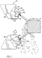
- FIG. 1 there is illustrated the scarfing apparatus 10 in accordance with the present invention.
- Two scarfing apparatus 10 are illustrated in two positions, one above and one below the plane of a steel slab to be scarfed.
- the scarfing apparatus 10 are usually mounted across the width of supports 11 ( Figure 11) and arranged to scarf the top and bottom of a slab S .
- side scarfing units 10a are positioned on supports 11 to aid in scarfing the sides of a slab S ( Figure 11), which normally is positioned on a movable table (not shown) that can extend through the rectangular housing configuration defined by the scarfing apparatus.
- the scarfing apparatus 10 is constructed to allow a stand-off distance from a slab during preheating and scarfing so that preheating and scarfing can occur on the end corner of the slab without having slag or other hot, molten metal fall onto the apparatus, as occurs in other, conventional scarfing units during initial starting adjacent the slab edge.
- the apparatus includes a manifold and head assembly 14 , typically formed from a bronze or copper material, and having fuel and oxygen gas channels (shown schematically) which receive and distribute oxygen and fuel gas.
- the manifold and head assembly 14 includes a formed slot 16 along one edge in which upper and lower preheat blocks 20 , 22 are mounted. Both the upper and lower preheat blocks 20 , 22 extend outward from the manifold and head assembly 14 a substantially equal distance to each other.
- the upper and lower preheat blocks are preferably formed from copper.
- the upper and lower preheat blocks 20 , 22 are spaced from each other to define an oxygen slot 26 and discharge orifice 28 of predetermined size for receiving a flow of scarfing oxygen from the manifold and head assembly and discharging the scarfing oxygen through the discharge orifice onto the steel slab 8 ( Figures 2 and 6).
- An oxygen flow channel, illustrated schematically at 30 extends through the manifold and head assembly 14 and connects to the entrance end of the oxygen scarfing slot 26 .
- the lower preheat block 22 includes a fuel gas flow channel, indicated schematically at 32 , and a discharge end 34 positioned adjacent to the scarfing slot 26 .
- Fuel gas flows through a fuel gas flow channel 36 of the manifold and head assembly 14 into the fuel gas passageway 32 and exits as a scarfing flame during scarfing.
- a riding shoe 38 is positioned along the underside of the lower preheat block 22 and the manifold and head assembly 16 .
- the riding shoe 38 includes a lower slab engaging surface 40 having slab engaging skids 41 adapted to contact the slab to position the scarfing discharge orifice 28 as well as the other exiting fuel and oxygen flows a predetermined distance from the steel slab.
- the lower scarfing apparatus 10 is inverted and the riding shoe 38 is positioned to engage the bottom surface of the steel slabs S .
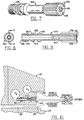
- Each upper preheat block 20 includes a base member 42 , and an extension member 43 secured to the base member 42 and extending forwardly therefrom.
- a plurality of preheat nozzle inserts 44 ( Figures 3-6) are mounted adjacent to each other in a row across the width of the extension member 43 .
- Each nozzle insert 44 is formed as a longitudinally extending, substantially cylindrically configured body member extending into the extension member 43 ( Figure 6).
- the nozzle inserts 44 preferably are each formed of a unitary piece of brass or copper with opposing gas entrance and discharge ends 46 , 48 ( Figure 4). Each nozzle insert 44 is mounted within a mounting opening 50 in the extension member 43 .
- An O-ring 52 is positioned on the outer circumference of the nozzle insert 44 at the entrance end and aids in centering and removably securing the nozzle insert 44 within the mounting opening 50 of the upper preheat block 20 . Additionally, the O-ring serves as a seal to segregate oxygen and fuel gas.
- a mounting plate 54 is secured to the upper preheat block and engages the discharge ends 48 of the nozzle inserts 44 .
- the mounting plate 54 also aids in retaining the nozzle inserts 44 within the mounting openings 50 .
- the mounting plate 54 includes holes which align and center the discharge ends 48 of the nozzle inserts 44 .
- the mounting plate 54 is secured to the upper preheat block 20 by fasteners, such as machine bolts 58 ( Figure 3).
- a central bore 60 extends axially through the nozzle insert 44 .
- An oxygen flow channel 62 within the manifold and head assembly 14 passes gas into an upper preheat block fuel channel 64 and through the central bore 60 in communication with the channel 64 ( Figure 2).
- the central bore 60 includes a first converging portion 66 , a throat portion 68 , and a diverging end portion 70 (Figure 4).
- the converging portion 66 tapers inward at a high angle as shown in Figure 4.
- the second, diverging portion 70 tapers outward at a smaller angle.
- the diameter of the diverging portion 70 at the oxygen discharge end is less than the diameter of the bore before converging.
- the bore before converging could be a smaller diameter than the exit diameter, or the bore could be designed straight completely through.
- oxygen gas received into the bore is constricted first within the converging portion where the gas velocity is increased.
- the oxygen then exits the discharge end as a high-velocity, preferably supersonic, accurately directed stream against the slab S .
- a retaining ring 72 is formed on the discharge end 48 of the nozzle insert 44 .
- the discharge end 48 includes elongate, concentric flutes 74 forming fuel gas flow channels 76 around the nozzle insert periphery through which fuel gas flows outward from the nozzle in substantially parallel, concentric flow around the central flow of oxygen.
- Fuel gas is delivered through an upper preheat block channel 78 ( Figure 2) and then onto the outer surface of the nozzle insert 44 and into the fuel gas channels 76 by the flutes.
- the concentric flow of fuel gas around the central flow of oxygen prevents a fuel gas flow intersection with the oxygen adjacent the nozzles.
- the momentum of the oxygen is maintained as it exits the nozzle insert 44 .
- Mixing of oxygen and fuel gas occurs further downstream to produce a hotter flame at a more extended distance from the preheat blocks.
- a forwardly protruding portion of the extension member 43 forms a shield plate 80 ( Figures 2 and 3), which is positioned in spaced relation above the insert plate 54 to form a slot 82 .
- An oxygen flow channel 64a extends off from the central oxygen flow channel 64 and through the upper preheat block to the slot 82 . Oxygen discharged through the slot 82 forms a shielded oxygen flow for the oxygen and fuel gas flowing from the nozzle insert 44 .
- the apparatus 10 are positioned as shown in Figure 1, including the side scarfing units (not shown), and the flows of oxygen and fuel gas through the various passageways are controlled to preheat the slab S .
- the nozzle insert 44 provides an efficient oxygen and fuel gas flow outward from the apparatus 10 without a sharp fuel gas flow intersection with the oxygen adjacent the nozzles, the momentum of the oxygen exiting the central bore is maintained until it intersects the fuel gas further downstream from the preheat blocks.
- a diagonal standoff distance is increased as compared to other conventional scarfing apparatus.
- a diagonal standoff distance as high as fifteen inches has been achieved.
- the slag and molten steel cannot drop onto the apparatus and the scarfing operation can begin at the end portion of the slab. Additionally, during continued use of the apparatus, the discharge end of the nozzle insert may become worn.
- the nozzle insert 44 can be readily replaced by removing the mounting plate 54 , and then removing the damaged nozzle insert 44 . A new nozzle insert 44 is inserted within the mounting hole 50 .
- Figures 7-10 illustrate a second embodiment of the nozzle insert in accordance with the present invention at 144 .
- the insert 144 is composed of a unitary piece of metallic material, such as brass or copper, and it includes a converging-diverging bore 160 to facilitate the production of supersonic flow therethrough.
- the exterior surface includes a plurality of flutes 174 along about one quarter of the longitudinal length of the body member adjacent the forward discharge end 148 , and the exterior surface also includes an externally threaded portion 145 adjacent the rear end 146 .
- This threaded portion 145 is adapted to engage a mating threaded portion in the cylindrical opening of the block, note Figure 10, and to facilitate the engagement and disengagement of this threaded interconnection, the bore of the insert is provided with a hex socket 151 at the forward discharge end which is adapted to be engaged by an allen wrench or the like.
- the insert 144 of Figures 7-10 also includes a pair of longitudinally spaced apart shoulders 153 , 154 positioned between the flutes and the externally threaded portion, and so as to form an annular channel 155 therebetween which is adapted to receive a resilient O-ring 152 .
- the rearward shoulder 153 also includes a rearwardly facing frusto-conical surface portion 160 which is adapted to form a metal to metal seat with a mating surface in the cylindrical opening of the supporting block.
- FIG 12 the prior art method of initiating near end scarfing one to two inches in from the end of a steel slab is illustrated and shown with a prior art apparatus having an overhanging preheat block.
- the scarfing apparatus begins its preheat one or two inches inward of the edge. In this preheat position, the apparatus has about a 0.5 inch vertical standoff above the slab, creating about a 1.25 inch diagonal standoff distance.
- a gullet G is formed across the width of the slab edge.
- the scarfing apparatus is positioned as shown in Figure 13.
- the diagonal standoff distance of the present invention is greater, ranging from six to ten inches.
- the horizontal standoff distance is preferably between about three to five inches, as compared to the other prior art method in which there is no horizontal standoff separation and the prior art apparatus is positioned above the steel slab.
- the vertical standoff distance is preferably between about 1.5 to 2.0 inches as compared to the prior art method in which the vertical standoff preheating distance is only 0.5 inches.
- the diagonal standoff distance may be defined as the distance from the front of the nozzle inserts 44 or 144 to the front corner of the workpiece.
- the horizontal standoff distance is the horizontal distance between a vertical plane containing the front of the nozzles and the end of the workpiece, and the vertical standoff distance is the vertical distance between a horizontal plane containing the skids 41 and the upper surface of the workpiece.
- the table (not shown) on which the steel slab rests is moved into a position in which the scarfing apparatus 10 are positioned over and adjacent the slab.
- the scarfing units are closed as in conventional scarfing operations, and then the table is retracted into the preheat position ( Figures 11 and 13).
- the scarfing apparatus preheat fuel gas is ignited at a low flow rate, and the preheat oxygen is also discharged at a low flow rate. Also, in the illustrated embodiment, a small volume flow of oxygen is concurrently directed through the scarfing slot 26 to provide a lower shield flow. The preheat fuel gas flow rate is then increased.
- the oxygen preheat flow is increased, and as best seen in Figure 6, this flow includes a stabilizing stream immediately above the preheating gas stream emanating from the nozzles formed by the inserts 44 or 144 .
- the oxygen flow rate is increased to about twice as much as normal oxygen preheat flow rates for the prior art methods and scarfing apparatus.
- the central stream of oxygen is discharged at a substantially supersonic speed
- the concentric stream of fuel gas is discharged at a speed less than the speed of the central stream.
- the upper and lower oxygen stabilizing streams are discharged at respective speeds which are less than the speed of the stream of fuel gas.
- the preheat oxygen flow is substantially reduced as shown in Figure 14, and the flow of scarfing oxygen is generated.
- the scarfing oxygen has reached its peak pressure and flow rate, the preheating fuel gas is reduced, and the table holding the steel slab is moved toward the scarfing apparatus.
- the "dead time" in which the scarfing oxygen remains until table movement is about two seconds.
- the table is initially moved forward at a first relatively slow speed, which is typically about 3 to 4 meters per minute, which is about one-fourth the normal speed of scarfing. After a predetermined period, its speed is increased to the normal scarfing speed, which is about four times as fast as the first speed.
- the flow rate of the oxygen is decreased slightly at the time when the table speed reaches the normal scarfing speed.
- Scarfing then continues as in normal prior art apparatus.
- a stream of fuel gas is concurrently discharged from the discharge end 34 of the fuel gas channel 32 of the lower block, to facilitate maintenance of the oxidizing reaction.
- the manifold and head assembly closes so that it moves into contact and "floats" on the moving workpiece.
- the closing operation is commenced substantially concurrently with the acceleration of the workpiece from its initial speed to its operating or final scarfing speed. Also, the closing operation is timed to terminate substantially concurrently with the workpiece reaching its final scarfing speed.
- Figure 15 illustrates a modification of the starting procedure.
- the scarfing oxygen delivery does not commence as early as in the embodiment of Figure 14, nor does it ramp up to a large rate and then back off as in Figure 14.
- the scarfing oxygen is smoothly increased during the acceleration of the table. The choice of these operating parameters is dependent in large measure to the initial standoff distance between the manifold and head assembly, and the workpiece.
- FIG 16 illustrates the timing of the machine closing process and workpiece acceleration in the embodiment of Figure 15, in somewhat more detail.
Abstract
Description
- This invention relates to a method and apparatus for thermochemically scarfing a metal workpiece and which allows a significant diagonal stand-off distance from the end of the workpiece during preheating and scarfing initiation so that molten metal is not blown onto the scarfing apparatus.
- Steel slabs commonly are conditioned by moving scarfing units along the top, bottom and side surfaces of a steel slab to eliminate surface defects such as cracks, seams and slag intrusions. One conventional scarfing apparatus includes top, side and bottom scarfing units that are mounted across the width and end portions of a support. The top, side and bottom units are arranged to scarf all sides of the slab.
- Both top, side, and bottom units include a manifold and head assembly, which receives and distributes oxygen and fuel gas to upper and lower preheat blocks. The upper and lower preheat blocks are spaced from each other to define between the two blocks an oxygen scarfing slot through which a quantity of oxygen is blown onto the slab surface to enable scarfing. The lower preheat block includes a fuel gas channel having a discharge end positioned adjacent the oxygen slot for discharging a fuel gas adjacent the oxygen flow.
- As illustrated for example in U.S. Patent No. 4,115,154, the upper preheat block typically is a one-piece unit that includes oxygen and fuel gas channels each having discharge orifices to define nozzles through which a combination of oxygen and fuel gas is discharged for preheating the slab before scarfing. Later, a postmix flow of oxygen and fuel gas provides for scarfing. To maintain a proper vertical stand-off distance of the nozzle exit from the steel slab, the top and bottom scarfing units include riding shoes positioned on respective lower preheat blocks. Because the integrally formed nozzles do not provide for a high speed gas flow outward from the scarfing units, the total diagonal stand-off distance, i.e., the vertical stand-off distance and horizontal stand-off distance (the lead distance from the scarfing unit to the slab) is small, and the scarfing units must be placed in close proximity to the slab during preheating. Thus, in a conventional scarfing unit as illustrated in the above referenced patent, the upper preheat block extends forward and hangs over the lower preheat block to direct the preheating stream of gas discharged from the upper preheat block onto the slab during preheating.
- Because the upper preheat block extends forwardly beyond the lower preheat block during initial preheating of the slab, the molten steel formed on the slab edge may drip onto portions of the upper preheat block positioned below the slab. The molten steel may damage the upper preheat block requiring reconstruction or replacement of the preheat blocks. To avoid this problem, during initial preheating, the scarfing units are positioned adjacent the slab and heat the slab one to two inches inward of the end to prevent steel and slag from dripping onto the forwardly extending preheat block. As a result of starting the scarfing process inward from the end of the steel slab, the one or two inches of unscarfed steel must be either scrapped or hand scarfed, leading to excessive production costs.
- Additionally, through continued use, the discharge ends forming the upper preheat nozzles may wear. Because the preheat nozzles are integrally formed in the upper preheat block, any damage to the nozzle area mandates either replacement of the entire upper preheat block, or removal of the damaged area and the brazing of new material onto the upper preheat block.
- It is accordingly an object of the present invention to provide a scarfing method and apparatus that allows a greater diagonal standoff distance from the metal workpiece during preheating and scarfing, to permit initial scarfing at the front portion of the slab in such a way that molten metal is not blown onto the scarfing apparatus.
- It is another object of the present invention to provide a method of initiating end scarfing on the end of a steel slab and in which the scarfing apparatus is positioned a diagonal standoff distance sufficient to allow full width preheating of the end of the slab without having a significant amount of molten steel and other particles fall or be blown onto the scarfing apparatus.
- The above and other objects and advantages of the present invention are achieved in the embodiments illustrated herein by the provision of a method and apparatus for thermochemically scarfing a metal workpiece and which includes the step of preheating an area on the surface of a stationary workpiece. This preheating step includes directing a preheating gas stream toward the area, and the preheating gas stream comprises a high speed central stream of oxidizing gas and a concentric stream of fuel gas coaxially about the central stream so as to be essentially parallel to the flow of the central stream. As a result, the momentum of the central stream is substantially maintained. Thereafter a stream of scarfing oxidizing gas is directed at an acute angle toward the preheated area of the workpiece, and relative movement is initiated between the workpiece and the stream of scarfing oxidizing gas so as to produce a scarfing cut.
- In the preferred embodiment, the preheating gas stream is stabilized, by directing a first stabilizing stream of oxidizing gas immediately above the preheating gas stream, and directing a second stabilizing stream of oxidizing gas immediately below the preheating stream. Preferably, the second stabilizing stream is discharged from the same port which later discharges the scarfing oxidizing gas.
- The apparatus of the present invention comprises a manifold and head assembly which includes upper and lower preheat blocks, with the blocks being spaced from each other to define an oxygen scarfing slot therebetween. A plurality of discharge nozzles are mounted adjacent to each other in a row above and parallel to the slot, with each nozzle including a central bore for receiving an oxidizing gas from the manifold and head assembly and discharging the same as the high speed central stream. Outer channel means is also provided for receiving a fuel gas from the manifold and head assembly and discharging the same in a substantially concentric stream disposed coaxially about and parallel to the central stream of oxidizing gas.
- In accordance with the more specific aspects of the present invention, the method includes the steps of positioning the manifold and head assembly at a diagonal standoff distance from an end of an elongate metal workpiece, preheating the end of the metal workpiece and including generating a high speed stream of oxidizing gas through the central bore of the nozzles and while generating a stream of fuel gas through the outer channel means of the nozzles. The streams are ignited and directed toward the end of the metal workpiece, and then the streams of the oxidizing gas and fuel gas from the nozzles are reduced to a low flow rate. Scarfing of the workpiece then commences, which includes generating a high speed stream of scarfing oxidizing gas from the slot, and while moving the workpiece horizontally toward and then past the manifold and head assembly so as to produce a scarfing cut.
- In the preferred embodiment, the preheat nozzles are nozzle inserts. Each nozzle insert is adapted to form a nozzle when mounted in a cylindrical opening in the supporting block, and each comprises a generally cylindrical body member defining a longitudinal axis and a forward discharge end and a rear end. A central bore extends through the body member along the longitudinal axis, and a plurality of longitudinally extending flutes are spaced about the exterior surface of the body member and along a portion of the length thereof adjacent the forward discharge end. When the insert is mounted in the cylindrical opening of the supporting block, a high speed flow of oxygen may be directed through the central bore, and a substantially concentric stream of fuel gas may be directed through the channels which are formed between the flutes and the cylindrical opening, so as to maintain the momentum of the oxygen as it exits the central bore.
- In the preferred embodiment, the central bore of the nozzle insert includes a first converging portion and a second diverging portion terminating in an oxygen discharge end of the nozzle insert. The diameter of the diverging portion at the oxygen discharge end is less than the diameter of the bore before converging. This construction provides for a high speed, and preferably supersonic, oxygen flow from the central bore.
- Also in the preferred embodiment, the lower preheat block includes a fuel gas flow channel and discharge end positioned adjacent the oxygen slot defined between the upper and lower preheat blocks. The upper preheat block includes a slot positioned above the row of nozzles. The slot extends through the upper preheat block for receiving a flow of oxygen from the manifold and head assembly and forming a shielding oxygen flow for the gas exiting the discharge end of the nozzles.
- In the preferred method, the diagonal standoff distance is between about six to ten inches during preheating of the slab. The horizontal standoff distance from the steel slab is between about three to five inches during preheating of the slab, and the vertical standoff distance from the steel slab is between-about one and one half and three inches.
- The step of moving the workpiece includes accelerating the workpiece over a predetermined time period in order to reach a final scarfing speed, and in accordance with the preferred embodiment of the invention, the manifold and head assembly is closed so as to move into contact with the moving workpiece during the time the workpiece is accelerating. Also, it is preferred to accelerate the workpiece in two stages, with the closing of the manifold and head assembly occurring during the second stage.
- Some of the objects and advantages of the present invention having been set forth above, other objects and advantages will appear as the description proceeds, when taken in conjunction with the accompanying drawings, in which:
- Figure 1 is a schematic side elevation view of upper and lower scarfing apparatus positioned for preheating and scarfing of a steel slab;
- Figure 2 is an enlarged, schematic side elevation view of the upper scarfing apparatus of Figure 1;
- Figure 3 is a front elevation view of the scarfing apparatus showing a plurality of nozzle inserts mounted in the upper preheat block;
- Figure 4 is a perspective view of a nozzle insert in accordance with one embodiment of the present invention;
- Figure 5 is a sectional view of the nozzle insert shown in Figure 4;
- Figure 6 is a fragmentary sectional view of the upper preheat block and illustrating the nozzle insert of Figures 4 and 5 and the preheating gas streams;
- Figure 7 is a perspective view of a second embodiment of the nozzle insert;
- Figure 8 is an end view of the nozzle insert shown in Figure 7;
- Figure 9 is a sectional view of the insert taken substantially along the line 9-9 of Figure 8;
- Figure 10 is a view similar to Figure 6, but illustrating the nozzle insert of Figures 7-9;
- Figure 11 is a schematic end view of scarfing apparatus positioned around a steel slab to be scarfed;
- Figure 12 is a schematic illustration of a prior art method of initiating end scarfing of a steel slab;
- Figure 13 is a schematic illustration of the method of initiating end scarfing of a steel slab in accordance with the present invention;
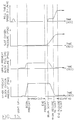
- Figure 14 is a graph of various steps involved in the preheating and initiation of end scarfing of a steel slab;
- Figure 15 is a graph similar to Figure 14 but illustrating a modified procedure; and
- Figure 16 is a graph illustrating the relationship roll table (i.e. workpiece) speed and scarfing oxygen pressure during scarfing initiation.
- Referring now to the drawings, and more particularly to Figure 1, there is illustrated the scarfing
apparatus 10 in accordance with the present invention. Two scarfingapparatus 10 are illustrated in two positions, one above and one below the plane of a steel slab to be scarfed. The scarfingapparatus 10 are usually mounted across the width of supports 11 (Figure 11) and arranged to scarf the top and bottom of a slab S. Additionally,side scarfing units 10a are positioned on supports 11 to aid in scarfing the sides of a slab S (Figure 11), which normally is positioned on a movable table (not shown) that can extend through the rectangular housing configuration defined by the scarfing apparatus. - In accordance with the present invention, the scarfing
apparatus 10 is constructed to allow a stand-off distance from a slab during preheating and scarfing so that preheating and scarfing can occur on the end corner of the slab without having slag or other hot, molten metal fall onto the apparatus, as occurs in other, conventional scarfing units during initial starting adjacent the slab edge. - As shown in greater detail in the schematic illustration of Figure 2, the apparatus includes a manifold and
head assembly 14, typically formed from a bronze or copper material, and having fuel and oxygen gas channels (shown schematically) which receive and distribute oxygen and fuel gas. The manifold andhead assembly 14 includes a formedslot 16 along one edge in which upper and lower preheat blocks 20, 22 are mounted. Both the upper and lower preheat blocks 20, 22 extend outward from the manifold and head assembly 14 a substantially equal distance to each other. The upper and lower preheat blocks are preferably formed from copper. - The upper and lower preheat blocks 20, 22 are spaced from each other to define an
oxygen slot 26 anddischarge orifice 28 of predetermined size for receiving a flow of scarfing oxygen from the manifold and head assembly and discharging the scarfing oxygen through the discharge orifice onto the steel slab 8 (Figures 2 and 6). An oxygen flow channel, illustrated schematically at 30, extends through the manifold andhead assembly 14 and connects to the entrance end of theoxygen scarfing slot 26. - The
lower preheat block 22 includes a fuel gas flow channel, indicated schematically at 32, and a discharge end 34 positioned adjacent to the scarfingslot 26. Fuel gas flows through a fuelgas flow channel 36 of the manifold andhead assembly 14 into thefuel gas passageway 32 and exits as a scarfing flame during scarfing. A ridingshoe 38 is positioned along the underside of thelower preheat block 22 and the manifold andhead assembly 16. The ridingshoe 38 includes a lowerslab engaging surface 40 havingslab engaging skids 41 adapted to contact the slab to position the scarfingdischarge orifice 28 as well as the other exiting fuel and oxygen flows a predetermined distance from the steel slab. As shown in Figure 1, thelower scarfing apparatus 10 is inverted and the ridingshoe 38 is positioned to engage the bottom surface of the steel slabs S. - Each
upper preheat block 20 includes abase member 42, and anextension member 43 secured to thebase member 42 and extending forwardly therefrom. A plurality of preheat nozzle inserts 44 (Figures 3-6) are mounted adjacent to each other in a row across the width of theextension member 43. Eachnozzle insert 44 is formed as a longitudinally extending, substantially cylindrically configured body member extending into the extension member 43 (Figure 6). The nozzle inserts 44 preferably are each formed of a unitary piece of brass or copper with opposing gas entrance and discharge ends 46, 48 (Figure 4). Eachnozzle insert 44 is mounted within a mountingopening 50 in theextension member 43. An O-ring 52 is positioned on the outer circumference of thenozzle insert 44 at the entrance end and aids in centering and removably securing thenozzle insert 44 within the mountingopening 50 of theupper preheat block 20. Additionally, the O-ring serves as a seal to segregate oxygen and fuel gas. - A mounting
plate 54 is secured to the upper preheat block and engages the discharge ends 48 of the nozzle inserts 44. The mountingplate 54 also aids in retaining the nozzle inserts 44 within the mountingopenings 50. The mountingplate 54 includes holes which align and center the discharge ends 48 of the nozzle inserts 44. The mountingplate 54 is secured to theupper preheat block 20 by fasteners, such as machine bolts 58 (Figure 3). - As illustrated in greater detail in Figure 4, a
central bore 60 extends axially through thenozzle insert 44. Anoxygen flow channel 62 within the manifold andhead assembly 14 passes gas into an upper preheatblock fuel channel 64 and through thecentral bore 60 in communication with the channel 64 (Figure 2). Thecentral bore 60 includes a first converging portion 66, a throat portion 68, and a diverging end portion 70 (Figure 4). The converging portion 66 tapers inward at a high angle as shown in Figure 4. The second, divergingportion 70 tapers outward at a smaller angle. In the preferred embodiment the diameter of the divergingportion 70 at the oxygen discharge end is less than the diameter of the bore before converging. However, the bore before converging could be a smaller diameter than the exit diameter, or the bore could be designed straight completely through. Thus, oxygen gas received into the bore is constricted first within the converging portion where the gas velocity is increased. The oxygen then exits the discharge end as a high-velocity, preferably supersonic, accurately directed stream against the slab S. - A retaining
ring 72 is formed on the discharge end 48 of thenozzle insert 44. As best seen in Figure 5, thedischarge end 48 includes elongate,concentric flutes 74 forming fuelgas flow channels 76 around the nozzle insert periphery through which fuel gas flows outward from the nozzle in substantially parallel, concentric flow around the central flow of oxygen. Fuel gas is delivered through an upper preheat block channel 78 (Figure 2) and then onto the outer surface of thenozzle insert 44 and into thefuel gas channels 76 by the flutes. The concentric flow of fuel gas around the central flow of oxygen prevents a fuel gas flow intersection with the oxygen adjacent the nozzles. Thus, the momentum of the oxygen is maintained as it exits thenozzle insert 44. Mixing of oxygen and fuel gas occurs further downstream to produce a hotter flame at a more extended distance from the preheat blocks. - A forwardly protruding portion of the
extension member 43 forms a shield plate 80 (Figures 2 and 3), which is positioned in spaced relation above theinsert plate 54 to form aslot 82. Anoxygen flow channel 64a extends off from the centraloxygen flow channel 64 and through the upper preheat block to theslot 82. Oxygen discharged through theslot 82 forms a shielded oxygen flow for the oxygen and fuel gas flowing from thenozzle insert 44. - During operation, the
apparatus 10 are positioned as shown in Figure 1, including the side scarfing units (not shown), and the flows of oxygen and fuel gas through the various passageways are controlled to preheat the slab S. Because thenozzle insert 44 provides an efficient oxygen and fuel gas flow outward from theapparatus 10 without a sharp fuel gas flow intersection with the oxygen adjacent the nozzles, the momentum of the oxygen exiting the central bore is maintained until it intersects the fuel gas further downstream from the preheat blocks. As a result, a more enhanced and hotter flame is achieved, and the diagonal standoff distance is increased as compared to other conventional scarfing apparatus. With the present invention, a diagonal standoff distance as high as fifteen inches has been achieved. As a result of this greater diagonal stand-off distance, during initial pre-heating of the slab S, the slag and molten steel cannot drop onto the apparatus and the scarfing operation can begin at the end portion of the slab. Additionally, during continued use of the apparatus, the discharge end of the nozzle insert may become worn. Thenozzle insert 44 can be readily replaced by removing the mountingplate 54, and then removing the damagednozzle insert 44. Anew nozzle insert 44 is inserted within the mountinghole 50. - Figures 7-10 illustrate a second embodiment of the nozzle insert in accordance with the present invention at 144. In this embodiment, the
insert 144 is composed of a unitary piece of metallic material, such as brass or copper, and it includes a converging-divergingbore 160 to facilitate the production of supersonic flow therethrough. The exterior surface includes a plurality offlutes 174 along about one quarter of the longitudinal length of the body member adjacent theforward discharge end 148, and the exterior surface also includes an externally threadedportion 145 adjacent therear end 146. This threadedportion 145 is adapted to engage a mating threaded portion in the cylindrical opening of the block, note Figure 10, and to facilitate the engagement and disengagement of this threaded interconnection, the bore of the insert is provided with ahex socket 151 at the forward discharge end which is adapted to be engaged by an allen wrench or the like. - The
insert 144 of Figures 7-10 also includes a pair of longitudinally spaced apart shoulders 153, 154 positioned between the flutes and the externally threaded portion, and so as to form an annular channel 155 therebetween which is adapted to receive a resilient O-ring 152. Therearward shoulder 153 also includes a rearwardly facing frusto-conical surface portion 160 which is adapted to form a metal to metal seat with a mating surface in the cylindrical opening of the supporting block. - In Figure 12, the prior art method of initiating near end scarfing one to two inches in from the end of a steel slab is illustrated and shown with a prior art apparatus having an overhanging preheat block. As shown, the scarfing apparatus begins its preheat one or two inches inward of the edge. In this preheat position, the apparatus has about a 0.5 inch vertical standoff above the slab, creating about a 1.25 inch diagonal standoff distance. As a result of starting the preheat inward from the slab end, a gullet G is formed across the width of the slab edge.
- Looking now at Figure 13, a preferred method of scarfing in accordance with the present invention is illustrated. During initial preheating, the scarfing apparatus is positioned as shown in Figure 13. As compared to the prior art preheating method in which the diagonal standoff distance is only 1.25 inches (Figure 12), the diagonal standoff distance of the present invention is greater, ranging from six to ten inches. The horizontal standoff distance is preferably between about three to five inches, as compared to the other prior art method in which there is no horizontal standoff separation and the prior art apparatus is positioned above the steel slab. The vertical standoff distance is preferably between about 1.5 to 2.0 inches as compared to the prior art method in which the vertical standoff preheating distance is only 0.5 inches.
- As used herein, the diagonal standoff distance may be defined as the distance from the front of the nozzle inserts 44 or 144 to the front corner of the workpiece. Similarly, the horizontal standoff distance is the horizontal distance between a vertical plane containing the front of the nozzles and the end of the workpiece, and the vertical standoff distance is the vertical distance between a horizontal plane containing the
skids 41 and the upper surface of the workpiece. - The steps involved in the initial starting of the scarfing process will now be described in more detail with reference to Figures 6 and 14. To initiate preheating, the table (not shown) on which the steel slab rests is moved into a position in which the
scarfing apparatus 10 are positioned over and adjacent the slab. The scarfing units are closed as in conventional scarfing operations, and then the table is retracted into the preheat position (Figures 11 and 13). The scarfing apparatus preheat fuel gas is ignited at a low flow rate, and the preheat oxygen is also discharged at a low flow rate. Also, in the illustrated embodiment, a small volume flow of oxygen is concurrently directed through the scarfingslot 26 to provide a lower shield flow. The preheat fuel gas flow rate is then increased. Just after the preheat fuel gas flow rate is increased, the oxygen preheat flow is increased, and as best seen in Figure 6, this flow includes a stabilizing stream immediately above the preheating gas stream emanating from the nozzles formed by theinserts - In one preferred embodiment, the central stream of oxygen is discharged at a substantially supersonic speed, and the concentric stream of fuel gas is discharged at a speed less than the speed of the central stream. Also, the upper and lower oxygen stabilizing streams are discharged at respective speeds which are less than the speed of the stream of fuel gas.
- Once the steel slab is preheated, the preheat oxygen flow is substantially reduced as shown in Figure 14, and the flow of scarfing oxygen is generated. When the scarfing oxygen has reached its peak pressure and flow rate, the preheating fuel gas is reduced, and the table holding the steel slab is moved toward the scarfing apparatus. In the preferred embodiment, the "dead time" in which the scarfing oxygen remains until table movement is about two seconds.
- The table is initially moved forward at a first relatively slow speed, which is typically about 3 to 4 meters per minute, which is about one-fourth the normal speed of scarfing. After a predetermined period, its speed is increased to the normal scarfing speed, which is about four times as fast as the first speed. The flow rate of the oxygen is decreased slightly at the time when the table speed reaches the normal scarfing speed. Scarfing then continues as in normal prior art apparatus. Preferably, a stream of fuel gas is concurrently discharged from the discharge end 34 of the
fuel gas channel 32 of the lower block, to facilitate maintenance of the oxidizing reaction. Also, as illustrated in Figure 14, the manifold and head assembly closes so that it moves into contact and "floats" on the moving workpiece. The closing operation is commenced substantially concurrently with the acceleration of the workpiece from its initial speed to its operating or final scarfing speed. Also, the closing operation is timed to terminate substantially concurrently with the workpiece reaching its final scarfing speed. - Figure 15 illustrates a modification of the starting procedure. In this embodiment, the scarfing oxygen delivery does not commence as early as in the embodiment of Figure 14, nor does it ramp up to a large rate and then back off as in Figure 14. In Figure 15, the scarfing oxygen is smoothly increased during the acceleration of the table. The choice of these operating parameters is dependent in large measure to the initial standoff distance between the manifold and head assembly, and the workpiece.
- Figure 16 illustrates the timing of the machine closing process and workpiece acceleration in the embodiment of Figure 15, in somewhat more detail.
- In the drawings and specification, there has been set forth a preferred embodiment of this invention, and even though specific terms are used, they are used in a generic and descriptive sense only and not for purposes of limitation.
Claims (8)
- An insert for forming a nozzle (144) when mounted in a cylindrical opening in a supporting member and comprising:
a generally cylindrical body member defining a longitudinal axis and a forward discharge end (148) and a rear end (146); and
a central bore (160) extending through said body member along said longitudinal axis,
said insert being characterised by a plurality of longitudinal extending substantially parallel flutes (174) spaced about the exterior surface of said body member and along a portion of the length thereof adjacent to said forward discharge end (148), said flutes (174) extending longitudinally along less than about one half of the longitudinal length of said body member and extending to said forward discharge end (148) thereof, and the rear end portion (145) of said body member being externally threaded so as to be adapted to engage a mating threaded portion in the cylindrical opening of the supporting member (20), and whereby when the insert is mounted in the cylindrical opening of the supporting member a high speed gas flow may be directed through said central bore and a substantially concentric stream may be directed through the channels which are formed between said flutes (174) and the cylindrical opening. - The insert as defined in claim 1, including a resilient O-ring positioned circumferentially about said insert at a location spaced from said flutes (174) so as to form a seal with a mating portion of the cylindrical opening of the supporting member.
- The insert as defined in claim 1 or 2, wherein said central bore (160) includes a first converging portion and a second diverging portion which terminates at said discharge end (148) thereof.
- The insert as defined in claim 3, wherein the diameter of the diverging portion of said central bore (160) at said discharge end (148) is less than the diameter of said bore before converging.
- The insert as defined in any one of the preceding claims, wherein said body member is composed of a unitary piece of metallic material.
- The insert as defined in any one of the preceding claims, wherein said central bore (160) includes a multi-sided socket (151) formed at said forward discharge end (148) which is arranged to be engaged by an Allen wrench or the like.
- The insert as defined in claim 6, wherein said body member includes a pair of longitudinally spaced apart shoulders (153, 154) positioned between said flutes (174) and said externally threaded portion (145) and forming an annular channel (155) therebetween for receiving a resilient sealing O-ring.
- The insert as defined in claim 7, wherein one of said shoulders (153, 154) includes a frusto-conical surface portion (160) which faces toward said rear end (146) for forming a metal-to-metal seal with a mating portion in the cylindrical opening of the supporting member (20).
Applications Claiming Priority (5)
| Application Number | Priority Date | Filing Date | Title |
|---|---|---|---|
| US07/805,111 US5234658A (en) | 1991-12-09 | 1991-12-09 | Scarfing apparatus |
| US805111 | 1991-12-09 | ||
| US07/948,027 US5304256A (en) | 1991-12-09 | 1992-09-21 | Scarfing method |
| EP92310845A EP0546727B1 (en) | 1991-12-09 | 1992-11-27 | Scarfing method and apparatus |
| US948027 | 1993-03-19 |
Related Parent Applications (2)
| Application Number | Title | Priority Date | Filing Date |
|---|---|---|---|
| EP92310845A Division EP0546727B1 (en) | 1991-12-09 | 1992-11-27 | Scarfing method and apparatus |
| EP92310845.0 Division | 1992-11-27 |
Publications (3)
| Publication Number | Publication Date |
|---|---|
| EP0705656A2 true EP0705656A2 (en) | 1996-04-10 |
| EP0705656A3 EP0705656A3 (en) | 1996-05-15 |
| EP0705656B1 EP0705656B1 (en) | 1998-01-28 |
Family
ID=27122752
Family Applications (2)
| Application Number | Title | Priority Date | Filing Date |
|---|---|---|---|
| EP95119086A Expired - Lifetime EP0705656B1 (en) | 1991-12-09 | 1992-11-27 | Insert for a scarfing method and apparatus |
| EP92310845A Expired - Lifetime EP0546727B1 (en) | 1991-12-09 | 1992-11-27 | Scarfing method and apparatus |
Family Applications After (1)
| Application Number | Title | Priority Date | Filing Date |
|---|---|---|---|
| EP92310845A Expired - Lifetime EP0546727B1 (en) | 1991-12-09 | 1992-11-27 | Scarfing method and apparatus |
Country Status (8)
| Country | Link |
|---|---|
| US (2) | US5304256A (en) |
| EP (2) | EP0705656B1 (en) |
| JP (1) | JPH0653305B2 (en) |
| KR (1) | KR970008471B1 (en) |
| CN (1) | CN1042004C (en) |
| AT (2) | ATE141843T1 (en) |
| CA (1) | CA2084395C (en) |
| DE (2) | DE69213182T2 (en) |
Cited By (1)
| Publication number | Priority date | Publication date | Assignee | Title |
|---|---|---|---|---|
| DE102006034014A1 (en) * | 2006-02-23 | 2007-10-31 | Egon Evertz Kg (Gmbh & Co.) | Flame deseaming burner has nozzle arranged in head and circularly arranged gas supply channels has central gas supply opening |
Families Citing this family (19)
| Publication number | Priority date | Publication date | Assignee | Title |
|---|---|---|---|---|
| US5358221A (en) * | 1991-12-09 | 1994-10-25 | The Esab Group, Inc. | Block assembly for use in metal scarfing apparatus |
| US5497976A (en) * | 1995-01-18 | 1996-03-12 | The Esab Group, Inc. | Lower block assembly for use in metal scarfing apparatus |
| US5520370A (en) * | 1995-02-01 | 1996-05-28 | The Esab Group, Inc. | Gas distribution manifold for metal scarfing apparatus |
| US6174491B1 (en) | 1998-09-18 | 2001-01-16 | The Esab Group, Inc. | Lower pre-heat block for use in metal scarfing apparatus |
| AU1571901A (en) * | 1999-10-29 | 2001-05-14 | Matthew P. Pasulka | Accelerated steel cutting methods and machines for implementing such methods |
| JP3710998B2 (en) * | 2000-07-18 | 2005-10-26 | 日本スピング株式会社 | Welding method |
| US7134615B2 (en) * | 2002-07-31 | 2006-11-14 | Caterpillar Inc | Nozzle insert for mixed mode fuel injector |
| US7648086B2 (en) * | 2004-12-24 | 2010-01-19 | Hans-Joachim Bernd Struck | Nozzle device for use in a paper machine, board machine, pulp dewatering machine or similar machines |
| DE102007024247B3 (en) * | 2007-05-15 | 2008-11-06 | Lechler Gmbh | High pressure nozzle and method of making a high pressure nozzle |
| JP5251784B2 (en) * | 2009-08-10 | 2013-07-31 | 新日鐵住金株式会社 | Scarfing equipment |
| KR101189516B1 (en) * | 2010-02-08 | 2012-10-10 | 주식회사 포스코 | Slab processing method and slab processing system |
| KR101243206B1 (en) * | 2010-12-20 | 2013-03-13 | 주식회사 포스코 | Method for controlling scarfing speed of four-side scarfing apparatus |
| GB2507719A (en) * | 2012-09-25 | 2014-05-14 | Pillarhouse Int Ltd | Method and apparatus for improving selective soldering |
| DE102013101184A1 (en) * | 2013-02-07 | 2014-08-07 | Gega Lotz Gmbh | Flämmblockbaugruppe |
| WO2015099372A1 (en) * | 2013-12-23 | 2015-07-02 | 주식회사 포스코 | Slab scarfing apparatus and method for controlling same |
| JP6790873B2 (en) * | 2017-01-27 | 2020-11-25 | 日本製鉄株式会社 | Hot scarfer |
| JP6885270B2 (en) * | 2017-09-11 | 2021-06-09 | 日本製鉄株式会社 | Slab melting method |
| JP7401731B2 (en) * | 2019-07-17 | 2023-12-20 | 日本製鉄株式会社 | Steel material fusing equipment and steel material fusing method |
| CN114473132A (en) * | 2022-04-19 | 2022-05-13 | 振东冶金科技江苏有限公司 | Regulating valve with local microcirculation regulating function for corner cleaning |
Citations (1)
| Publication number | Priority date | Publication date | Assignee | Title |
|---|---|---|---|---|
| US4115154A (en) | 1977-09-26 | 1978-09-19 | Union Carbide Corporation | Method and apparatus for producing a post-mixed, stabilized scarfing pre-heating flame |
Family Cites Families (22)
| Publication number | Priority date | Publication date | Assignee | Title |
|---|---|---|---|---|
| US2468824A (en) * | 1944-11-23 | 1949-05-03 | Air Reduction | Multipiece cutting tip |
| US2531006A (en) * | 1946-12-30 | 1950-11-21 | Smith Welding Equipment Corp | Tip for cutting blowtorches |
| US2496923A (en) * | 1947-03-21 | 1950-02-07 | John D Walters | Tip structure for gas torches |
| US2521199A (en) * | 1947-06-14 | 1950-09-05 | Linde Air Prod Co | Method of and apparatus for high-speed, high-pressure oxygen cutting of metals |
| US2838431A (en) * | 1953-05-26 | 1958-06-10 | Union Carbide Corp | Method and apparatus for thermochemical metal scarfing |
| DE1213203B (en) * | 1962-06-25 | 1966-03-24 | Union Carbide Corp | Method for lightening metallic workpieces |
| US3231431A (en) * | 1964-06-24 | 1966-01-25 | Union Carbide Corp | Post-mixed fuel gas preheat scarfing |
| US3230116A (en) * | 1964-10-23 | 1966-01-18 | Union Carbide Corp | Moving end starts in mechanized scarfing |
| US3477646A (en) * | 1967-01-06 | 1969-11-11 | Union Carbide Corp | Scarfing unit |
| YU159370A (en) * | 1969-06-25 | 1977-06-30 | Union Carbide Corp | Device for preheating and melting the surface layer of metal blocks |
| DD102614A1 (en) * | 1973-03-27 | 1973-12-20 | ||
| US4038108A (en) * | 1976-05-10 | 1977-07-26 | Union Carbide Corporation | Method and apparatus for making an instantaneous thermochemical start |
| DE2633719C2 (en) * | 1976-07-27 | 1986-06-26 | Linde Ag, 6200 Wiesbaden | Method for operating a cutting torch and nozzle for carrying out the method |
| DE2948777A1 (en) * | 1979-12-04 | 1981-06-11 | Linde Ag, 6200 Wiesbaden | Autogenous flame cutting, esp. using oxy-acetylene - where air is added to heating flame to ensure adequate preheating of thick workpieces |
| JPS6049813B2 (en) * | 1980-08-21 | 1985-11-05 | 清二 加川 | crater |
| DE8309304U1 (en) * | 1983-03-29 | 1983-11-03 | GeGa Gesellschaft für Gasetechnik Lotz GmbH & Co KG, 6238 Hofheim | Strand cutting machine for cutting with cutting breaks |
| US4455176A (en) * | 1983-05-17 | 1984-06-19 | Union Carbide Corporation | Post-mixed oxy-fuel gas cutting torch and nozzle and method of oxy-fuel gas cutting |
| CA1323828C (en) * | 1986-10-22 | 1993-11-02 | Ronald Elmer Fuhrhop | Scarfing nozzles |
| WO1989002051A1 (en) * | 1987-09-02 | 1989-03-09 | Aga Aktiebolag | A method to generate an oxidizing flame, a burner and a use for a burner |
| JPH0274377A (en) * | 1988-09-09 | 1990-03-14 | Mitsubishi Kasei Corp | Conducting thermal transfer recording material |
| US4954683A (en) * | 1989-05-26 | 1990-09-04 | Thermal Dynamics Corporation | Plasma arc gouger |
| EP0513414B1 (en) * | 1991-05-16 | 1996-12-11 | Hotwork International S.A. | Nozzle device for controlling a gas stream |
-
1992
- 1992-09-21 US US07/948,027 patent/US5304256A/en not_active Expired - Lifetime
- 1992-11-27 AT AT92310845T patent/ATE141843T1/en not_active IP Right Cessation
- 1992-11-27 EP EP95119086A patent/EP0705656B1/en not_active Expired - Lifetime
- 1992-11-27 DE DE69213182T patent/DE69213182T2/en not_active Expired - Lifetime
- 1992-11-27 AT AT95119086T patent/ATE162746T1/en not_active IP Right Cessation
- 1992-11-27 DE DE69224309T patent/DE69224309T2/en not_active Expired - Lifetime
- 1992-11-27 EP EP92310845A patent/EP0546727B1/en not_active Expired - Lifetime
- 1992-12-02 CA CA002084395A patent/CA2084395C/en not_active Expired - Fee Related
- 1992-12-05 KR KR1019920023427A patent/KR970008471B1/en not_active IP Right Cessation
- 1992-12-08 JP JP4351422A patent/JPH0653305B2/en not_active Expired - Lifetime
- 1992-12-09 CN CN92113707A patent/CN1042004C/en not_active Expired - Fee Related
- 1992-12-10 US US07/988,450 patent/US5333841A/en not_active Expired - Lifetime
Patent Citations (1)
| Publication number | Priority date | Publication date | Assignee | Title |
|---|---|---|---|---|
| US4115154A (en) | 1977-09-26 | 1978-09-19 | Union Carbide Corporation | Method and apparatus for producing a post-mixed, stabilized scarfing pre-heating flame |
Cited By (1)
| Publication number | Priority date | Publication date | Assignee | Title |
|---|---|---|---|---|
| DE102006034014A1 (en) * | 2006-02-23 | 2007-10-31 | Egon Evertz Kg (Gmbh & Co.) | Flame deseaming burner has nozzle arranged in head and circularly arranged gas supply channels has central gas supply opening |
Also Published As
| Publication number | Publication date |
|---|---|
| CN1042004C (en) | 1999-02-10 |
| ATE141843T1 (en) | 1996-09-15 |
| CA2084395C (en) | 1998-08-04 |
| CN1075905A (en) | 1993-09-08 |
| EP0705656B1 (en) | 1998-01-28 |
| US5333841A (en) | 1994-08-02 |
| JPH05329635A (en) | 1993-12-14 |
| JPH0653305B2 (en) | 1994-07-20 |
| KR930012166A (en) | 1993-07-20 |
| KR970008471B1 (en) | 1997-05-24 |
| EP0546727B1 (en) | 1996-08-28 |
| EP0705656A3 (en) | 1996-05-15 |
| DE69224309D1 (en) | 1998-03-05 |
| US5304256A (en) | 1994-04-19 |
| CA2084395A1 (en) | 1993-06-10 |
| EP0546727A1 (en) | 1993-06-16 |
| ATE162746T1 (en) | 1998-02-15 |
| DE69224309T2 (en) | 1998-09-17 |
| DE69213182D1 (en) | 1996-10-02 |
| DE69213182T2 (en) | 1997-03-20 |
Similar Documents
| Publication | Publication Date | Title |
|---|---|---|
| EP0546727B1 (en) | Scarfing method and apparatus | |
| US2451422A (en) | Thermochemical removal of metal with a flux-forming powder in the oxygen cutting stream | |
| EP0589561B1 (en) | Block Assembly for use in metal scarfing apparatus | |
| US2353318A (en) | Nozzle for desurfacing metal | |
| JPH02192699A (en) | Nozzle for plasma torch and method of introducing powder flow into plasma column of plasma torch | |
| US4836447A (en) | Duct-stabilized flame-spray method and apparatus | |
| US2290295A (en) | Method and apparatus for desurfacing metal | |
| US5234658A (en) | Scarfing apparatus | |
| EP0163776A2 (en) | Highly concentrated supersonic flame spray method and apparatus with improved material feed | |
| EP0987078B1 (en) | Lower pre-heat block for use in metal scarfing apparatus | |
| US2536201A (en) | Thermochemical metal removal method and apparatus | |
| EP0722803B1 (en) | Lower block assembly for use in metal scarfing apparatus | |
| US4243436A (en) | Instantaneous scarfing by means of a pilot puddle | |
| US3216867A (en) | Thermochemical scarfing process | |
| US2433539A (en) | Blowpipe nozzle | |
| KR970006321B1 (en) | Block assembly for use in metal scarfing apparatus | |
| US2627826A (en) | Thermochemical material removal | |
| JP2000141030A (en) | Powder cutting device | |
| US2556786A (en) | Method of thermochemically severing tubular metal members | |
| US2626880A (en) | Thermochemical material removal | |
| US2794755A (en) | Flat powder stream forming process | |
| WO2010061596A1 (en) | Apparatus for scarfing steel bar and method for scarfing steel bar | |
| CA1142067A (en) | Instantaneous scarfing by means of a pilot puddle | |
| JPS6029309B2 (en) | Flame jet method and apparatus | |
| JPH0724588A (en) | Laser beam cutting machine |
Legal Events
| Date | Code | Title | Description |
|---|---|---|---|
| PUAI | Public reference made under article 153(3) epc to a published international application that has entered the european phase |
Free format text: ORIGINAL CODE: 0009012 |
|
| PUAL | Search report despatched |
Free format text: ORIGINAL CODE: 0009013 |
|
| 17P | Request for examination filed |
Effective date: 19951213 |
|
| AC | Divisional application: reference to earlier application |
Ref document number: 546727 Country of ref document: EP |
|
| AK | Designated contracting states |
Kind code of ref document: A2 Designated state(s): AT DE FR GB |
|
| AK | Designated contracting states |
Kind code of ref document: A3 Designated state(s): AT DE FR GB |
|
| RHK1 | Main classification (correction) |
Ipc: B23K 7/08 |
|
| RIN1 | Information on inventor provided before grant (corrected) |
Inventor name: DAWSON, JOHN G., JR. Inventor name: GUSKY, FRANK J. Inventor name: SHOWALTER,MICHAEL S. |
|
| GRAG | Despatch of communication of intention to grant |
Free format text: ORIGINAL CODE: EPIDOS AGRA |
|
| 17Q | First examination report despatched |
Effective date: 19970326 |
|
| GRAG | Despatch of communication of intention to grant |
Free format text: ORIGINAL CODE: EPIDOS AGRA |
|
| GRAH | Despatch of communication of intention to grant a patent |
Free format text: ORIGINAL CODE: EPIDOS IGRA |
|
| GRAH | Despatch of communication of intention to grant a patent |
Free format text: ORIGINAL CODE: EPIDOS IGRA |
|
| GRAA | (expected) grant |
Free format text: ORIGINAL CODE: 0009210 |
|
| AC | Divisional application: reference to earlier application |
Ref document number: 546727 Country of ref document: EP |
|
| AK | Designated contracting states |
Kind code of ref document: B1 Designated state(s): AT DE FR GB |
|
| REF | Corresponds to: |
Ref document number: 162746 Country of ref document: AT Date of ref document: 19980215 Kind code of ref document: T |
|
| REF | Corresponds to: |
Ref document number: 69224309 Country of ref document: DE Date of ref document: 19980305 |
|
| ET | Fr: translation filed | ||
| PLBE | No opposition filed within time limit |
Free format text: ORIGINAL CODE: 0009261 |
|
| STAA | Information on the status of an ep patent application or granted ep patent |
Free format text: STATUS: NO OPPOSITION FILED WITHIN TIME LIMIT |
|
| 26N | No opposition filed | ||
| REG | Reference to a national code |
Ref country code: GB Ref legal event code: IF02 |
|
| PGFP | Annual fee paid to national office [announced via postgrant information from national office to epo] |
Ref country code: DE Payment date: 20091127 Year of fee payment: 18 Ref country code: AT Payment date: 20091103 Year of fee payment: 18 |
|
| PGFP | Annual fee paid to national office [announced via postgrant information from national office to epo] |
Ref country code: GB Payment date: 20091125 Year of fee payment: 18 Ref country code: FR Payment date: 20091201 Year of fee payment: 18 |
|
| GBPC | Gb: european patent ceased through non-payment of renewal fee |
Effective date: 20101127 |
|
| REG | Reference to a national code |
Ref country code: FR Ref legal event code: ST Effective date: 20110801 |
|
| PG25 | Lapsed in a contracting state [announced via postgrant information from national office to epo] |
Ref country code: AT Free format text: LAPSE BECAUSE OF NON-PAYMENT OF DUE FEES Effective date: 20101127 |
|
| REG | Reference to a national code |
Ref country code: DE Ref legal event code: R119 Ref document number: 69224309 Country of ref document: DE Effective date: 20110601 Ref country code: DE Ref legal event code: R119 Ref document number: 69224309 Country of ref document: DE Effective date: 20110531 |
|
| PG25 | Lapsed in a contracting state [announced via postgrant information from national office to epo] |
Ref country code: DE Free format text: LAPSE BECAUSE OF NON-PAYMENT OF DUE FEES Effective date: 20110531 |
|
| PG25 | Lapsed in a contracting state [announced via postgrant information from national office to epo] |
Ref country code: FR Free format text: LAPSE BECAUSE OF NON-PAYMENT OF DUE FEES Effective date: 20101130 |
|
| PG25 | Lapsed in a contracting state [announced via postgrant information from national office to epo] |
Ref country code: GB Free format text: LAPSE BECAUSE OF NON-PAYMENT OF DUE FEES Effective date: 20101127 |