EP0705535B1 - Modulare Stütze für verpflanzte Pflanzen - Google Patents
Modulare Stütze für verpflanzte Pflanzen Download PDFInfo
- Publication number
- EP0705535B1 EP0705535B1 EP95115636A EP95115636A EP0705535B1 EP 0705535 B1 EP0705535 B1 EP 0705535B1 EP 95115636 A EP95115636 A EP 95115636A EP 95115636 A EP95115636 A EP 95115636A EP 0705535 B1 EP0705535 B1 EP 0705535B1
- Authority
- EP
- European Patent Office
- Prior art keywords
- elements
- plant
- trunk
- horizontal
- rod
- Prior art date
- Legal status (The legal status is an assumption and is not a legal conclusion. Google has not performed a legal analysis and makes no representation as to the accuracy of the status listed.)
- Expired - Lifetime
Links
- 239000002689 soil Substances 0.000 claims abstract description 12
- 239000000463 material Substances 0.000 claims abstract description 5
- 230000001681 protective effect Effects 0.000 claims abstract description 3
- 239000002023 wood Substances 0.000 claims description 3
- 238000004873 anchoring Methods 0.000 claims description 2
- 239000003337 fertilizer Substances 0.000 claims description 2
- 241000196324 Embryophyta Species 0.000 description 43
- 229920001971 elastomer Polymers 0.000 description 3
- 239000004033 plastic Substances 0.000 description 3
- 229920003023 plastic Polymers 0.000 description 3
- 239000005060 rubber Substances 0.000 description 3
- 244000025254 Cannabis sativa Species 0.000 description 2
- 239000002184 metal Substances 0.000 description 2
- 241001465754 Metazoa Species 0.000 description 1
- 238000009434 installation Methods 0.000 description 1
- 230000000670 limiting effect Effects 0.000 description 1
- 238000000034 method Methods 0.000 description 1
- 229920003052 natural elastomer Polymers 0.000 description 1
- 229920001194 natural rubber Polymers 0.000 description 1
- 230000000284 resting effect Effects 0.000 description 1
- 125000006850 spacer group Chemical group 0.000 description 1
- 229920003051 synthetic elastomer Polymers 0.000 description 1
- 239000005061 synthetic rubber Substances 0.000 description 1
Images

Classifications
-
- A—HUMAN NECESSITIES
- A01—AGRICULTURE; FORESTRY; ANIMAL HUSBANDRY; HUNTING; TRAPPING; FISHING
- A01G—HORTICULTURE; CULTIVATION OF VEGETABLES, FLOWERS, RICE, FRUIT, VINES, HOPS OR SEAWEED; FORESTRY; WATERING
- A01G23/00—Forestry
- A01G23/02—Transplanting, uprooting, felling or delimbing trees
- A01G23/04—Transplanting trees; Devices for grasping the root ball, e.g. stump forceps; Wrappings or packages for transporting trees
-
- A—HUMAN NECESSITIES
- A01—AGRICULTURE; FORESTRY; ANIMAL HUSBANDRY; HUNTING; TRAPPING; FISHING
- A01G—HORTICULTURE; CULTIVATION OF VEGETABLES, FLOWERS, RICE, FRUIT, VINES, HOPS OR SEAWEED; FORESTRY; WATERING
- A01G17/00—Cultivation of hops, vines, fruit trees, or like trees
- A01G17/04—Supports for hops, vines, or trees
Definitions
- the present invention relates to a structure with modular components and openable collar, particularly adapted for supporting transplanted plants in an upright position in order to allow their root-taking and -forming.
- Transplanting a small- and medium-sized plant or tree currently entails removing the plant from its growing place so that a part of the soil that surrounds it, known as sod, remains attached to the roots; then a larger hole (approximately twice as large as the sod) is dug in the transplant area; the plant and the associated sod are placed in this larger hole, and then three (or more) supporting posts are inserted at the sides of the hole, orientating them towards the trunk of the plant. Thereafter, the ends of the supporting posts (known as braces) are tied to the plant with flexible means, such as ropes, metal cables, or the like. Finally, the hole is filled with soil, which is then tamped. With this supporting system, the transplanted plant remains upright with no danger that the sod might separate from the roots.
- braces lie outside the hole and are sometimes very long (for example three or four meters long in the case of large-size plants or trees) they occupy significant space around the plant and are thus aesthetically unpleasant. Additionally, the known braces constitute a dangerous obstacle for people and animals.
- braces protruding out of the soil that surrounds the plant also entail the drawback that they require cutting other young plants to provide them and hinder periodical cutting of the grass around the transplanted plant; said cutting, even after removing the braces, can cause damage to the bark of the plant, especially if lawn-mowers or the like are used.
- DE-A-4008580 discloses a method for securing trees against falling in which at least one earth anchor, which grips on a strong tree root, is inserted at least about 3 m deep into the ground.
- a principal aim of the present invention is to provide a supporting structure for transplanted plants that is conceived and structured so as to fully obviate the practical, economical, and aesthetic problems entailed by the use of braces arranged outside the soil affected by the plant, and most of all such that it can be reused several times, without practical difficulties and always with the same effectiveness and reliability, and which can also be used for transplanting potted plants or the like.
- An object of the invention is to provide a supporting structure of the above specified type that is structured so as to be easily adapted, quickly and without using accessories and/or operations for adapting the braces to the various situations, for plants the height and trunk diameter whereof vary significantly.
- said supporting structure uses three horizontal rod-like elements, two whereof are rigidly coupled to (or monolithic with) each other at one of their free ends and are longer than the third horizontal element, so as to form a single element that is curved at substantially 90° and is meant to accommodate the trunk of the plant in the curved region; the third horizontal element being shorter than the other elements and being detachably anchored thereto in the curved region between the two first elements; the plant being fastened to the structure by means of a half-collar or the like adjustable by means of screw-like spacers or the like; said fastening being such as to close, with the interposition of a flexible sleeve, the trunk of the plant between the curved region of the first two elements and the half-collar.
- said horizontal rod-like elements have the same length and each one is provided, at its free end, with a portion shaped like a circular arc; said circular arcs have screw-like anchoring means for their stable connection around the trunk of the plant after interposing a flexible sleeve-like sheath.
- said vertical rod-like elements are preferably constituted by straight tubular bodies adapted to allow, when required, the introduction of fertilizers in the soil that surrounds the roots of the transplanted plant.
- the supporting structure according to the invention is conceived and structured so as to remain installed, fully embedded and concealed in the hole formed in the soil in a known manner.
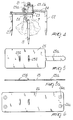
- Said structure in fact comprises three metallic rod-like elements 1-2-3 which, after placing the sod 6 with the roots in the hole 4, are driven vertically inside the hole 4, which is substantially quadrangular or even cylindrical and is formed in a known manner in the soil 5, at a substantially equal distance from each other and with an angular spacing as shown in figure 2, that is to say, so that they lie at the corners of an isosceles triangle or the like, in the central region whereof the sod is placed.
- Horizontal rod-like elements 8-9-10 are furthermore connected to said three vertical elements by virtue of screw means or the like; their length is adjustable so as to converge towards the plant or tree and then be able to fasten it regardless of the diameter of its trunk.
- the embodiment shown in figures 1 and 2 entails forming the horizontal elements 8 and 9 starting from a single rod-like element that is subsequently bent at an angle (approximately 90°) so as to form the two elements 8-9 and then allow to accommodate, in the curved region between the two elements 8-9, the trunk of the plant 7 above the sod.
- the third horizontal rod-like element 10, which is shorter than the previous ones, is furthermore connected by screw means or the like 10a to the curved region between the elements 8-9.
- the plant which is already located in the curved region (figure 2) between the elements 8-9, is then fastened by virtue of a collar 11 that is substantially a curved flat element having two opposite lugs 11a-11b which allow to tighten the collar around the trunk by virtue of two traction elements 12-12a anchored at right angles to the elements 8-9; said traction elements are threaded so that, by passing through holes formed in the lugs of the collar, said collar can be tightened around the plant by means of nuts.
- a sleeve-shaped tubular sheath 13 made of flexible material such as natural or synthetic rubber, nonrigid plastics, or the like, is interposed between said collar and the trunk.
- At least the horizontal traction elements 8-9 are made of two parts that can be telescopically adjusted in length with respect to each other by screwing or unscrewing a nut 14 that acts by resting on lugs that protrude from the traction elements on a threaded portion of the initial part 8a-9a of the two traction elements 8-9.
- the traction element 10 can also be provided so that it can elongate telescopically according to the requirements.
- the supporting structure with vertical rod-like elements can have three horizontal rigid elements or traction elements 15-16-17 (figure 3) of equal length; sectors of a cylindrical sleeve 15a-16a-17a are anchored to the free end of said elements that lies close to the trunk, and said sectors are provided, at their ends, with lugs that mate with each other so as to provide, by virtue of traction screws 18, a rigid tubular body that encloses the plant 7 and the corresponding flexible protective sleeve 13.
- the length of said screws 18 is such as to allow to fasten the cylindrical sectors 15a-16a-17a that form the collar on plants of different diameters.
- the structure is separated from the plant and extracted so that it can be reused for other transplants.
- the length of the elastic tubular sheath 13 can be such that it protrudes partially from the ground, so as to wrap around a part of the trunk, protecting it from the cutting devices of conventional lawn-mowers.
- the supporting structure can be constituted by four vertical elements 19-20-21-22 (figure 4) made of wood, metal, plastics, or the like, which are arranged inside a quadrangular hole and at the top whereof it is possible to anchor two identical horizontal elements 23-24 that are substantially two pairs of identical rod-like elements shaped like a V or the like and arranged so that they are mutually opposite and co-planar, as clearly shown in figure 4.
- the V-shaped elements 23-24 can be provided so that they can elongate telescopically to adapt them to the various dimensions of the plant to be supported; in this case, too, a fitting made of rubber or the like, having an adjustable height and length, is inserted between the plant and the portions of the elements that form the external quadrilateral.
- the rubber sleeve or gasket is in fact constituted by an elastic belt 25 or 26 (figures 5-5a and figure 6) having, in one case, a toothed tab 25a adapted to be wrapped in a tubular manner around the plant and then inserted in bridges 25b and then pulled so as to adhere to said plant.
- the elastic belt 26 (figure 6) can instead have, as securing means, once the tubular element has been formed, elastic press-studs 26a or the like.
- the dimensions of the vertical and horizontal rod-like elements, as well as the materials employed can vary according to the requirements; likewise, the dimensions and shape of the elastic belts and of the collar fastening system can also vary according to the requirements without abandoning the scope of the protection of the invention.
Landscapes
- Life Sciences & Earth Sciences (AREA)
- Environmental Sciences (AREA)
- Botany (AREA)
- Biodiversity & Conservation Biology (AREA)
- Ecology (AREA)
- Forests & Forestry (AREA)
- Supports For Plants (AREA)
- Hydroponics (AREA)
- Cultivation Receptacles Or Flower-Pots, Or Pots For Seedlings (AREA)
- Cultivation Of Plants (AREA)
Claims (7)
- Stützstruktur für zu versetzende Pflanzen, dadurch gekennzeichnet, daß sie mindestens drei stabartige Elemente (1, 2, 3; 19, 20, 21, 22) hat, die weitgehend vertikal und mit zueinander gleichen Abständen in den Boden eines Loches, das einer Pflanze (7) mit Wurzelballen (6) angepaßt ist, so einzutreiben sind, daß ihre oberen Enden teilweise unter dem Rand des Loches (4) liegen; daß ein horizontales stabartiges Element (8, 9, 10; 15, 16, 17; 23, 24) lösbar am oberen Ende eines jeden vertikalen stabartigen Elements (1, 2, 3; 19, 20, 21, 22) verankert und auf den Stamm der Pflanze (7) im mittleren Bereich des Loches (4) ausgerichtet ist; und daß mindestens eine Zwinge (11) zum Befestigen des Stammes der Pflanze (7) an den Enden der horizontalen Elemente (8, 9, 10; 15, 16, 17; 23, 24) eine einstellbare Breite hat und mit den horizontalen Elementen (8, 9, 10; 15, 16, 17; 23, 24) unter Zwischenlage einer Schutzhülse (13) aus flexiblem Material zwischen der Zwinge (11) und dem Stamm der Pflanze (7) verbindbar ist.
- Stützstruktur nach Anspruch 1, dadurch gekennzeichnet, daß sie drei horizontale stabartige Elemente (8, 9, 10) hat, von denen zwei (8, 9) an einem ihrer freien Enden starr miteinander verbunden und länger als das dritte horizontale Element (10) sind, so daß sie ein um etwa 90° gebogenes Element zur Anpassung an den Stamm einer Pflanze (7) in dem gebogenen Bereich bilden; daß das dritte horizontale Element (10) kürzer als die anderen Elemente (8, 9) ist und mit diesen in dem gebogenen Bereich zwischen den ersten beiden Elementen lösbar verankert ist; daß die Pflanze (7) an der Struktur durch eine einstellbare Halbzwinge (11) befestigt ist, die unter Zwischenlage einer flexiblen Hülse (13) den Stamm der Pflanze (7) zwischen dem gebogenen Bereich der ersten beiden Elemente (8, 9) und der Halbzwinge (11) einschließt.
- Stützstruktur nach Anspruch 1 und 2, dadurch gekennzeichnet, daß die horizontalen stabartigen Elemente (15, 16, 17) übereinstimmende Länge haben und jeweils an seinem freien Ende mit einem kreisbogenförmigen Teil (15a, 16a, 17a) versehen sind, und daß die kreisbogenförmigen Teile (15, 16a, 17a) schraubenartige Einstell- und Verankerungsmittel (18) zur stabilen Verbindung um den Stamm der Pflanze (7) herum haben, nachdem eine flexible hülsenartige Hülle (13) zwischengelegt ist.
- Stützstruktur nach den Ansprüchen 1 bis 3, dadurch gekennzeichnet, daß die vertikalen stabartigen Elemente (1, 2, 3; 19, 20, 21, 22) vorzugsweise durch gerade rohrförmige Körper gebildet sind, die erforderlichenfalls das Einführen von Dünger in den Boden (5) in der Umgebung der Wurzeln der versetzten Pflanze (7) erlauben.
- Stützstruktur nach den vorhergehenden Ansprüchen, dadurch gekennzeichnet, daß die rohrförmige Hülse (13) aus flexiblem Material eine solche Höhe oder Länge hat, daß sie aus der Oberfläche des Bodens (5) zum Schutz des unteren Teils der Pflanze (7) teilweise hervorsteht.
- Stützstruktur nach einem oder mehreren der vorhergehenden Ansprüche, dadurch gekennzeichnet, daß sie durch vier vertikale stabartige Elemente (19, 20, 21, 22) gebildet ist, die an den Ecken eines viereckigen Loches eingetrieben sind; daß die freien Enden zweier identischer horizontaler Elemente (23, 24), die gleichfalls aus Holz o.ä. bestehen, lösbar an dem oberen Ende der vertikalen stabartigen Elemente (19, 20, 21, 22) verankert sind; und daß die horizontalen Elemente (23, 24) durch Elementpaare gebildet sind, die V-förmig o.ä. angeordnet und einander gegenüberliegend in gemeinsamer Ebene angeordnet sind, so daß sie zwischen sich einen Rahmen zum Halten der zu versetzenden Pflanze (7) bilden.
- Stützstruktur nach den vorhergehenden Ansprüchen, dadurch gekennzeichnet, daß die Schutzhülse (13) oder Manschette durch ein elastisches Band (25, 26) mit gezahnter Lasche (25a) gebildet ist, die in Brücken (25b) einzuschieben sind, nachdem das Band (25, 26) um den Stamm der Pflanze (7) gewickelt ist, und dann gezogen werden, bis das rohrförmige Element stabil an dem Stamm befestigt ist, indem die Zähne der Lasche (25a) in der Brücke (25b) festsitzen.
Applications Claiming Priority (2)
| Application Number | Priority Date | Filing Date | Title |
|---|---|---|---|
| ITMI940670U | 1994-10-07 | ||
| IT94MI000670U IT234148Y1 (it) | 1994-10-07 | 1994-10-07 | Struttura ad elementi componibili ed a collare apribile, particolarmente adatta per il sostegno di piante trapiantate al fine |
Publications (2)
| Publication Number | Publication Date |
|---|---|
| EP0705535A1 EP0705535A1 (de) | 1996-04-10 |
| EP0705535B1 true EP0705535B1 (de) | 1998-04-29 |
Family
ID=11368522
Family Applications (1)
| Application Number | Title | Priority Date | Filing Date |
|---|---|---|---|
| EP95115636A Expired - Lifetime EP0705535B1 (de) | 1994-10-07 | 1995-10-04 | Modulare Stütze für verpflanzte Pflanzen |
Country Status (5)
| Country | Link |
|---|---|
| EP (1) | EP0705535B1 (de) |
| AT (1) | ATE165493T1 (de) |
| DE (1) | DE69502252T2 (de) |
| ES (1) | ES2117820T3 (de) |
| IT (1) | IT234148Y1 (de) |
Families Citing this family (10)
| Publication number | Priority date | Publication date | Assignee | Title |
|---|---|---|---|---|
| GB2322782B (en) * | 1997-03-07 | 2001-10-03 | Toho Leo Kabushiki Kaisha | Method of providing support to tree,as well as tree base support member and root ball retainer for use in the method |
| DE69816330T2 (de) * | 1997-10-28 | 2004-05-13 | Rockwool International A/S | Lärmschutzwand |
| ES2255813B1 (es) * | 2004-05-20 | 2007-07-01 | Gerard Passola Parcerissa | Procedimiento para trasladar objetos enterrados total o parcialmente en un terreno. |
| FR2983680B1 (fr) * | 2011-12-12 | 2015-01-23 | Novagreen | Systeme enterre de stabilisation d'arbres en motte |
| US10653079B1 (en) | 2016-08-25 | 2020-05-19 | Ginger Tree Innovations, LLC | Underground tree stake system |
| CN106962061B (zh) * | 2017-03-22 | 2020-03-20 | 浙江德润市政园林有限公司 | 一种园林用植物固定装置 |
| CN108551966A (zh) * | 2018-06-13 | 2018-09-21 | 麻江县睿林蓝莓有限公司 | 一种蓝莓种植用支撑装置 |
| CN112913571B (zh) * | 2021-03-31 | 2023-04-25 | 河南科技大学 | 用于新移植带土球大树的隐藏式支撑装置 |
| CN114467599A (zh) * | 2021-12-31 | 2022-05-13 | 刘芳玲 | 一种沃柑的节肥高效栽培方法 |
| CN117981552B (zh) * | 2024-02-26 | 2024-08-09 | 巨野关资果蔬种植专业合作社 | 一种樱桃种植营养液补给装置及方法 |
Family Cites Families (4)
| Publication number | Priority date | Publication date | Assignee | Title |
|---|---|---|---|---|
| US4520590A (en) * | 1983-04-13 | 1985-06-04 | Schuh Gerald J | Tree brace system |
| JPS6387919A (ja) * | 1986-10-01 | 1988-04-19 | 東邦パ−ライト株式会社 | 樹木の支持施工方法 |
| US4922653A (en) * | 1988-12-28 | 1990-05-08 | Alan Stone | Plant watering and feeding support system |
| DE4008580A1 (de) * | 1990-03-15 | 1991-09-19 | Merkel Klaus Dieter | Verfahren und vorrichtung zur sicherung von baeumen gegen umstuerzen |
-
1994
- 1994-10-07 IT IT94MI000670U patent/IT234148Y1/it active IP Right Grant
-
1995
- 1995-10-04 DE DE69502252T patent/DE69502252T2/de not_active Expired - Fee Related
- 1995-10-04 EP EP95115636A patent/EP0705535B1/de not_active Expired - Lifetime
- 1995-10-04 AT AT95115636T patent/ATE165493T1/de not_active IP Right Cessation
- 1995-10-04 ES ES95115636T patent/ES2117820T3/es not_active Expired - Lifetime
Also Published As
| Publication number | Publication date |
|---|---|
| ITMI940670U1 (it) | 1996-04-07 |
| DE69502252D1 (de) | 1998-06-04 |
| EP0705535A1 (de) | 1996-04-10 |
| ATE165493T1 (de) | 1998-05-15 |
| DE69502252T2 (de) | 1998-11-05 |
| IT234148Y1 (it) | 2000-02-23 |
| ITMI940670V0 (it) | 1994-10-07 |
| ES2117820T3 (es) | 1998-08-16 |
Similar Documents
| Publication | Publication Date | Title |
|---|---|---|
| US4520590A (en) | Tree brace system | |
| US6269589B1 (en) | Planter for trees, poles and other vertical surfaces | |
| EP0705535A1 (de) | Modulare Stütze für verpflanzte Pflanzen | |
| KR20190045806A (ko) | 수목 지지대 | |
| US6199818B1 (en) | Support device for a pole | |
| WO1995019695A1 (en) | Tree support device | |
| US6216387B1 (en) | Device for and method of plant support and fertilizer delivery | |
| US6371432B1 (en) | Support device | |
| KR101049249B1 (ko) | 수목 지하 지주 설치방법 | |
| US6708446B2 (en) | V-strap tree stabilizing assembly | |
| US4299052A (en) | Tree anchoring device | |
| US4454681A (en) | Method and means of securing a plant pot to a shelf | |
| GB2307170A (en) | Support for a vertical elongate member | |
| US20140183311A1 (en) | Tree Planter Harness | |
| JPH06169660A (ja) | 人工育成する樹木の固定方法と固定装置 | |
| JP3145458B2 (ja) | 樹木の植栽方法 | |
| JPH03112419A (ja) | 樹木の支持施工方法 | |
| JPH06141705A (ja) | 樹木の支持施工装置 | |
| GB2295952A (en) | Tree stable | |
| KR20010025472A (ko) | 수목 와이어 지주 | |
| KR200263806Y1 (ko) | 과수원의 보호망 지지용 강선 고정장치 | |
| KR880002426Y1 (ko) | 화분걸이가 부착된 가로수 보호지지대 | |
| KR0118689Y1 (ko) | 식수목의 지주대 | |
| US20020011023A1 (en) | Tree stabilizing assembly | |
| Meade et al. | Staking and Guying Newly Planted Trees |
Legal Events
| Date | Code | Title | Description |
|---|---|---|---|
| PUAI | Public reference made under article 153(3) epc to a published international application that has entered the european phase |
Free format text: ORIGINAL CODE: 0009012 |
|
| AK | Designated contracting states |
Kind code of ref document: A1 Designated state(s): AT BE CH DE DK ES FR GB GR IE IT LI NL PT SE |
|
| 17P | Request for examination filed |
Effective date: 19960930 |
|
| 17Q | First examination report despatched |
Effective date: 19961106 |
|
| GRAG | Despatch of communication of intention to grant |
Free format text: ORIGINAL CODE: EPIDOS AGRA |
|
| GRAG | Despatch of communication of intention to grant |
Free format text: ORIGINAL CODE: EPIDOS AGRA |
|
| GRAH | Despatch of communication of intention to grant a patent |
Free format text: ORIGINAL CODE: EPIDOS IGRA |
|
| GRAH | Despatch of communication of intention to grant a patent |
Free format text: ORIGINAL CODE: EPIDOS IGRA |
|
| GRAA | (expected) grant |
Free format text: ORIGINAL CODE: 0009210 |
|
| AK | Designated contracting states |
Kind code of ref document: B1 Designated state(s): AT BE CH DE DK ES FR GB GR IE IT LI NL PT SE |
|
| PG25 | Lapsed in a contracting state [announced via postgrant information from national office to epo] |
Ref country code: NL Free format text: LAPSE BECAUSE OF FAILURE TO SUBMIT A TRANSLATION OF THE DESCRIPTION OR TO PAY THE FEE WITHIN THE PRESCRIBED TIME-LIMIT Effective date: 19980429 Ref country code: LI Free format text: LAPSE BECAUSE OF FAILURE TO SUBMIT A TRANSLATION OF THE DESCRIPTION OR TO PAY THE FEE WITHIN THE PRESCRIBED TIME-LIMIT Effective date: 19980429 Ref country code: GR Free format text: LAPSE BECAUSE OF FAILURE TO SUBMIT A TRANSLATION OF THE DESCRIPTION OR TO PAY THE FEE WITHIN THE PRESCRIBED TIME-LIMIT Effective date: 19980429 Ref country code: CH Free format text: LAPSE BECAUSE OF FAILURE TO SUBMIT A TRANSLATION OF THE DESCRIPTION OR TO PAY THE FEE WITHIN THE PRESCRIBED TIME-LIMIT Effective date: 19980429 Ref country code: BE Free format text: LAPSE BECAUSE OF FAILURE TO SUBMIT A TRANSLATION OF THE DESCRIPTION OR TO PAY THE FEE WITHIN THE PRESCRIBED TIME-LIMIT Effective date: 19980429 |
|
| REF | Corresponds to: |
Ref document number: 165493 Country of ref document: AT Date of ref document: 19980515 Kind code of ref document: T |
|
| REG | Reference to a national code |
Ref country code: CH Ref legal event code: EP |
|
| REF | Corresponds to: |
Ref document number: 69502252 Country of ref document: DE Date of ref document: 19980604 |
|
| RAP2 | Party data changed (patent owner data changed or rights of a patent transferred) |
Owner name: TUTOR INTERNATIONAL S.N.C. DI ALTINI MARIO & GUGLI |
|
| ITF | It: translation for a ep patent filed | ||
| PG25 | Lapsed in a contracting state [announced via postgrant information from national office to epo] |
Ref country code: SE Free format text: LAPSE BECAUSE OF FAILURE TO SUBMIT A TRANSLATION OF THE DESCRIPTION OR TO PAY THE FEE WITHIN THE PRESCRIBED TIME-LIMIT Effective date: 19980729 Ref country code: PT Free format text: LAPSE BECAUSE OF FAILURE TO SUBMIT A TRANSLATION OF THE DESCRIPTION OR TO PAY THE FEE WITHIN THE PRESCRIBED TIME-LIMIT Effective date: 19980729 Ref country code: DK Free format text: LAPSE BECAUSE OF FAILURE TO SUBMIT A TRANSLATION OF THE DESCRIPTION OR TO PAY THE FEE WITHIN THE PRESCRIBED TIME-LIMIT Effective date: 19980729 |
|
| REG | Reference to a national code |
Ref country code: IE Ref legal event code: FG4D Free format text: 80111 |
|
| REG | Reference to a national code |
Ref country code: ES Ref legal event code: FG2A Ref document number: 2117820 Country of ref document: ES Kind code of ref document: T3 |
|
| NLT2 | Nl: modifications (of names), taken from the european patent patent bulletin |
Owner name: TUTOR INTERNATIONAL S.N.C. DI ALTINI MARIO & GUGLI |
|
| ET | Fr: translation filed | ||
| NLV1 | Nl: lapsed or annulled due to failure to fulfill the requirements of art. 29p and 29m of the patents act | ||
| PG25 | Lapsed in a contracting state [announced via postgrant information from national office to epo] |
Ref country code: IE Free format text: LAPSE BECAUSE OF NON-PAYMENT OF DUE FEES Effective date: 19981004 |
|
| REG | Reference to a national code |
Ref country code: CH Ref legal event code: PL |
|
| PLBE | No opposition filed within time limit |
Free format text: ORIGINAL CODE: 0009261 |
|
| STAA | Information on the status of an ep patent application or granted ep patent |
Free format text: STATUS: NO OPPOSITION FILED WITHIN TIME LIMIT |
|
| 26N | No opposition filed | ||
| REG | Reference to a national code |
Ref country code: GB Ref legal event code: IF02 |
|
| GBPC | Gb: european patent ceased through non-payment of renewal fee |
Effective date: 20031004 |
|
| REG | Reference to a national code |
Ref country code: GB Ref legal event code: 728V |
|
| REG | Reference to a national code |
Ref country code: GB Ref legal event code: 728Y |
|
| PGFP | Annual fee paid to national office [announced via postgrant information from national office to epo] |
Ref country code: GB Payment date: 20050331 Year of fee payment: 10 Ref country code: ES Payment date: 20050331 Year of fee payment: 10 |
|
| PGFP | Annual fee paid to national office [announced via postgrant information from national office to epo] |
Ref country code: AT Payment date: 20050401 Year of fee payment: 10 |
|
| PGFP | Annual fee paid to national office [announced via postgrant information from national office to epo] |
Ref country code: FR Payment date: 20050405 Year of fee payment: 10 |
|
| PGFP | Annual fee paid to national office [announced via postgrant information from national office to epo] |
Ref country code: DE Payment date: 20050429 Year of fee payment: 10 |
|
| PG25 | Lapsed in a contracting state [announced via postgrant information from national office to epo] |
Ref country code: GB Free format text: LAPSE BECAUSE OF NON-PAYMENT OF DUE FEES Effective date: 20051004 Ref country code: AT Free format text: LAPSE BECAUSE OF NON-PAYMENT OF DUE FEES Effective date: 20051004 |
|
| PG25 | Lapsed in a contracting state [announced via postgrant information from national office to epo] |
Ref country code: ES Free format text: LAPSE BECAUSE OF NON-PAYMENT OF DUE FEES Effective date: 20051005 |
|
| PG25 | Lapsed in a contracting state [announced via postgrant information from national office to epo] |
Ref country code: DE Free format text: LAPSE BECAUSE OF NON-PAYMENT OF DUE FEES Effective date: 20060503 |
|
| GBPC | Gb: european patent ceased through non-payment of renewal fee |
Effective date: 20051004 |
|
| PG25 | Lapsed in a contracting state [announced via postgrant information from national office to epo] |
Ref country code: FR Free format text: LAPSE BECAUSE OF NON-PAYMENT OF DUE FEES Effective date: 20060630 |
|
| REG | Reference to a national code |
Ref country code: FR Ref legal event code: ST Effective date: 20060630 |
|
| REG | Reference to a national code |
Ref country code: ES Ref legal event code: FD2A Effective date: 20051005 |
|
| PGFP | Annual fee paid to national office [announced via postgrant information from national office to epo] |
Ref country code: IT Payment date: 20091020 Year of fee payment: 15 |
|
| PG25 | Lapsed in a contracting state [announced via postgrant information from national office to epo] |
Ref country code: IT Free format text: LAPSE BECAUSE OF NON-PAYMENT OF DUE FEES Effective date: 20101004 |