EP0704952B1 - Circuit d'autosurveillance, notamment d'appareillage électrique et en particulier de disjoncteur haute tension à SF6 - Google Patents
Circuit d'autosurveillance, notamment d'appareillage électrique et en particulier de disjoncteur haute tension à SF6 Download PDFInfo
- Publication number
- EP0704952B1 EP0704952B1 EP19950402164 EP95402164A EP0704952B1 EP 0704952 B1 EP0704952 B1 EP 0704952B1 EP 19950402164 EP19950402164 EP 19950402164 EP 95402164 A EP95402164 A EP 95402164A EP 0704952 B1 EP0704952 B1 EP 0704952B1
- Authority
- EP
- European Patent Office
- Prior art keywords
- station
- stations
- terminal
- parameter
- transaction
- Prior art date
- Legal status (The legal status is an assumption and is not a legal conclusion. Google has not performed a legal analysis and makes no representation as to the accuracy of the status listed.)
- Expired - Lifetime
Links
Images

Classifications
-
- H—ELECTRICITY
- H02—GENERATION; CONVERSION OR DISTRIBUTION OF ELECTRIC POWER
- H02H—EMERGENCY PROTECTIVE CIRCUIT ARRANGEMENTS
- H02H3/00—Emergency protective circuit arrangements for automatic disconnection directly responsive to an undesired change from normal electric working condition with or without subsequent reconnection ; integrated protection
-
- G—PHYSICS
- G05—CONTROLLING; REGULATING
- G05B—CONTROL OR REGULATING SYSTEMS IN GENERAL; FUNCTIONAL ELEMENTS OF SUCH SYSTEMS; MONITORING OR TESTING ARRANGEMENTS FOR SUCH SYSTEMS OR ELEMENTS
- G05B19/00—Program-control systems
- G05B19/02—Program-control systems electric
- G05B19/418—Total factory control, i.e. centrally controlling a plurality of machines, e.g. direct or distributed numerical control [DNC], flexible manufacturing systems [FMS], integrated manufacturing systems [IMS] or computer integrated manufacturing [CIM]
- G05B19/4185—Total factory control, i.e. centrally controlling a plurality of machines, e.g. direct or distributed numerical control [DNC], flexible manufacturing systems [FMS], integrated manufacturing systems [IMS] or computer integrated manufacturing [CIM] characterised by the network communication
-
- Y—GENERAL TAGGING OF NEW TECHNOLOGICAL DEVELOPMENTS; GENERAL TAGGING OF CROSS-SECTIONAL TECHNOLOGIES SPANNING OVER SEVERAL SECTIONS OF THE IPC; TECHNICAL SUBJECTS COVERED BY FORMER USPC CROSS-REFERENCE ART COLLECTIONS [XRACs] AND DIGESTS
- Y02—TECHNOLOGIES OR APPLICATIONS FOR MITIGATION OR ADAPTATION AGAINST CLIMATE CHANGE
- Y02P—CLIMATE CHANGE MITIGATION TECHNOLOGIES IN THE PRODUCTION OR PROCESSING OF GOODS
- Y02P90/00—Enabling technologies with a potential contribution to greenhouse gas [GHG] emissions mitigation
- Y02P90/02—Total factory control, e.g. smart factories, flexible manufacturing systems [FMS] or integrated manufacturing systems [IMS]
-
- Y—GENERAL TAGGING OF NEW TECHNOLOGICAL DEVELOPMENTS; GENERAL TAGGING OF CROSS-SECTIONAL TECHNOLOGIES SPANNING OVER SEVERAL SECTIONS OF THE IPC; TECHNICAL SUBJECTS COVERED BY FORMER USPC CROSS-REFERENCE ART COLLECTIONS [XRACs] AND DIGESTS
- Y02—TECHNOLOGIES OR APPLICATIONS FOR MITIGATION OR ADAPTATION AGAINST CLIMATE CHANGE
- Y02P—CLIMATE CHANGE MITIGATION TECHNOLOGIES IN THE PRODUCTION OR PROCESSING OF GOODS
- Y02P90/00—Enabling technologies with a potential contribution to greenhouse gas [GHG] emissions mitigation
- Y02P90/80—Management or planning
Definitions
- the present invention relates to a circuit self-monitoring of apparatus, in particular of apparatus electrical such as a high voltage SF6 circuit breaker.
- apparatus electrical such as a high voltage SF6 circuit breaker.
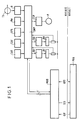
- the data of all these transducers is sent to a multiprocessor system SMP, constituting a base of local distributed data; the SMP system also receives closing and opening orders from PLCs and protections located on level 1, and represented in the figure by the rectangle PRA.
- SMP multiprocessor system
- the SMP system converts with the PRA stage through a MBD microcontroller, called remote terminal microcontroller, since it is located at a distance from the circuit breaker at monitor.
- the MBD microcontroller constitutes a basis for data which is the replica of the system database SMP.
- the link between the MBD microcontroller and the system SMP is done by fiber optic links, free of electromagnetic disturbances.
- the PRA stage can be connected to the MBD microcontroller by in different ways depending on the architecture of the control station command is conventional or digital.
- parallel links preferably with optical fibers, allow the transmission of orders O / F opening and closing, GIS and access to the database.
- FIG. 2 is a block diagram of the system SMP multiprocessor.
- the system consists of several microcontrollers each constituting as many databases and which provide, in addition to their application software individuals, software for communication with a network local RL, allowing to manage the database distributed data, refreshed periodically and guaranteeing in particular the simultaneous deposit of the same data in each of the distributed databases.
- a network local has been described in French patent application 92 06 921 published under the number FR-A-2 692 057.
- Functional anomalies are coded and stored for a posteriori analysis of the behavior of the circuit breaker.
- Two microcontrollers S5 and S6 (stations n ° 5 and n ° 6) monitor wear for each pole, respectively electrical contact and the density of the insulating gas SF6.
- station n ° 5 receives, in its base of data, information related to opening orders and closing; this station, in turn, provides "electrical wear” information.
- Station n ° 6 enriches the distributed database SF6 data relating to each pole.
- Stations S1 to S3 thus have access to their own information and can adopt the corresponding strategy when they receive an order.
- a GR microcontroller ensures network management local RL by designating, within its frames, which are the consuming and / or producing stations of such or such as given, at the rate of the periodicity of refresh of each data in the database distributed.
- a special TB card called a bus translator, allows the transition from a wired bus to BO optical buses.
- the wired copper bus for compatibility reasons electromagnetic, is thus strictly confined in the electronic rack, optical links avoiding the introduction of external disturbances.
- An S4 microcontroller (station n ° 4) ensures the software gateway between the LAN and a link LS series to level 1 microcomputer, which is preference of the PC (personal computer) type and which will be hereinafter referred to as PC.
- This connection allows, for maintenance purposes, constitute a human-machine interface to access, in reading, to the information contained in the database distributed.
- An object of the invention is to arrange this station and its programming so as to allow modification, by the Local or remote PC, operating thresholds of the system (SF6 alarms for example).
- the subject of the invention is a circuit device self-monitoring including a plurality of transducers for measuring the parameters of operation of said apparatus, said transducers of measurement providing data to a multiprocessor system comprising stations connected by a local network under the command of a network manager and constituting a base distributed data refreshed with periodicities data, the system can receive instructions from a higher level and provide it with answers, said level superior including a computer linked by a link serial to a gateway itself connected to said network, characterized in that said gateway is a microcontroller called terminal and connected to said network, said terminal interacting with stations through first messages corresponding to requests from the terminal and received by all stations in memory areas determined, called first dedicated areas, and second messages corresponding to responses from stations interrogated and received by said terminal in areas of determined memories, say second dedicated zones.
- the terminal is configured to be well of all the data in the distributed database and source of messages regarding requests for transaction.
- Transaction requests can be requests of reading a parameter in memory in a given station of the system or entering a new value of a parameter at a determined address of a memory of a given station.
- a request to register a new parameter is consisting of two words sent by the terminal and comprising each two bytes, the first indicating the nature of the transaction, the number of the destination station and the page number and memory index where the new parameter must be stored, the second word containing the value of the new parameter formatted on 14 bits, two bits being used for verification of the transaction.
- a read request includes a word sent by the terminal formatted on two bytes and indicating the nature of the transaction, the number of the destination station and the page number and memory index where the parameter must be sought, the response of the requested station being consisting of a two-byte word containing the value of parameter read at the address indicated, said word being formatted on 14 bits, two bits being used for verification of the transaction.
- the invention also relates to an apparatus electric characterized in that it comprises a circuit self-monitoring as indicated above.
- the invention also relates to a circuit breaker with high voltage at SF6, characterized in that it includes a self-monitoring circuit according to one of claims 1 at 5.
- the data for each of these types occupy two areas very distinct in the database: an area called “0" for periodic data and an area called “1" for periodic data.
- first dedicated memory areas each with a dimension of two bytes, referenced below by BAL1 and BAL2.
- BAL1 and BAL2 These mailboxes occupy for example, in page 0 of the memory, for BAL1 the indices FCh and FDh (in hexadecimal numbering) and, for BAL2, the FEh and FFh.
- zone "0” i memory zones having two bytes each, i being the station number of the multiprocessor system, these zones being called seconds dedicated memory areas, and referenced BAL3i and located for example so that the index of the first byte is ECh + 2i, the second byte being at the index EDh + 2i.
- the GR network manager designates the station n ° 4 as producer (or source) of the data contained in memories BAL1 and BAL2, the others stations being consumers (or sinks) of these data.
- station # 4 is well for all data from the distributed database.
- each of these memories BAL is attached to the corresponding station i, so that a station i is configured as the source of the contents of its memory BAL3i, but on the other hand, only the station n ° 4 is well of it and thus receives the contents of all BAL3i memories.
- the memory BAL1 concerns a transaction request by the PC.
- transaction we mean either a request for reading of a parameter, i.e. a request to write a new value of a parameter.
- a BAL 1 memory is shown below, comprising two bytes D0 to D7 at the addresses FCh and FDh respectively: BAL1 (transaction request) D7 D6 D5 D4 D3 D2 D1 D0 FCh nature operation * memory page number * station number requested FDh address (parameter index in the page)
- the two bits D7 and D6 of the first byte are assigned to the nature of the operation according to the following coding: Nature of the operation D7 D6 none (no operation) 0 0 parameter write request 1 0 parameter read request 0 1
- the station number requested is designated by bits D0 to D2 of the first byte and page number of station memory concerned by the transaction is designated by bits D3 to D5 of the first byte.
- the content of the second byte is used to designate the index in the memory page of the requested station.
- the memory BAL2 is used to write the new parameter to write, hereinafter called "PC data"; this parameter is formatted on 14 bytes, the bytes marked x in the diagram below, the bits D6 and D7 of the second byte being reserved for the protocol, as will be seen below.
- the device works as follows:
- BAL1 AND BAL2 being in zone "0" are aperiodic data and as such are sent to the stations via the local network and under the control of the network manager GR.
- the stations simultaneously detect the write request by the respective values "1" and "0" of bits D6 and D7 of the first byte of the first word; only one station is recognized by its address coded by the bits D0 to D2 of the first byte of the first word; this station registers in the prescribed page and index the new parameter read in BAL2 and jointly puts it back in its BAL3i for control by station n ° 4.
- the 14 bits of the new parameter are thus stored in BAL3i, as well as, for bits D6 and D7 of the second byte of BAL3i (also called “nature data”), the bits according to the table below: Nature data D7 D6 Invalid data 0 0 New parameter well received 1 0 The parameter requested in read is valid 0 1
- the message transmitted by the network is read by all the stations; only, the requested station recognizes itself and provides the response in the words "response transaction i" whose index of the first byte is equal to ECh + 2i, as indicated below where the y represent the parameter coded in 14 bits.
- the second octet bits D7 and D6 are coded as "01" to indicate to station 4 that the 14-bit data it contains is valid.
- D7 D6 D5 D4 D3 D2 D1 D0 BAL3 ECh + 2i y y y y y y y rep.
- station 4 When the requested station has responded, station 4, after checking in BAL3i the validity of the data received in response to its request, gives "transaction type” (D1D0 of the FCh index) to "00", indicating that there is no more transactions in progress, then the station requested (n ° 6 in the example chosen) resets "nature data” to "00"; of even unsolicited stations will keep nature bits data "to” 00 “indicating that the" transaction response "data are invalid.
- transaction type D1D0 of the FCh index
- the PC can also request acknowledgments of faults or teleactions by submitting your request in BAL1.
- the index in FDh will be operated by the stations concerned.
- the invention is not limited to ordering a circuit breaker. It applies mutatis mutandis to all switchgear, electric or not, including sensors or measurement transducers providing data to a multiprocessor system comprising stations connected in network under the control of a network manager and constituting a distributed database refreshed with given intervals, the network can receive in addition to instructions or instructions of a higher level.
- the invention allows self-monitoring of switchgear, in particular electrical, and in particular circuit breakers, which allows for example to run a predictive maintenance and operate in degraded mode between two effective maintenance.
Landscapes
- Engineering & Computer Science (AREA)
- Automation & Control Theory (AREA)
- Manufacturing & Machinery (AREA)
- Quality & Reliability (AREA)
- Physics & Mathematics (AREA)
- General Physics & Mathematics (AREA)
- General Engineering & Computer Science (AREA)
- Remote Monitoring And Control Of Power-Distribution Networks (AREA)
- Keying Circuit Devices (AREA)
- Emergency Protection Circuit Devices (AREA)
- Selective Calling Equipment (AREA)
- Driving Mechanisms And Operating Circuits Of Arc-Extinguishing High-Tension Switches (AREA)
- Computer And Data Communications (AREA)
- Gas-Insulated Switchgears (AREA)
Description
- pour chaque pôle du disjoncteur, un transducteur CAO indiquant que le pôle est en position ouverte,
- pour chaque pôle du disjoncteur, un transducteur CAF indiquant que le pôle est en position fermée,
- pour chaque pôle, un transducteur SF6 fournissant la valeur de la pression du gaz d'isolement SF6 dans le pôle,
- un transducteur PH indiquant la pression d'huile dans la commande du disjoncteur
- pour chaque pôle, un transducteur U élaborant, à partir de la mesure du courant dans le pôle par un transformateur d'intensité TI, une indication permettant l'évaluation de l'usure du pôle.
- réaliser le pilotage correct des bobines de fermeture (BF) et d'ouverture (BO), sans aucun contact conventionnel dans la chaíne, à l'aide des interrupteurs statiques (ISF et ISO respectivement),
- élaborer des informations de position du disjoncteur avec un très haut degré de sécurité, grâce à un algorithme qui exploite notamment les redondances entres les transducteurs CAO et CAF, ainsi que les informations de discordance éventuelle,
- assurer une réouverture automatique des trois pôles en cas de discordance à la fermeture,
- assurer pour chacune des manoeuvres le chronométrage des deux durées caractéristiques, à savoir la durée entre la réception de l'ordre et le départ de la position initiale et la durée entre le départ de la position initiale et l'arrivée dans la position finale,
- assurer le pilotage de regonflage de la commande hydraulique, au moyen d'une pompe P et également par des circuits dénués de tout contact conventionnel, grâce notamment à un interrupteur statique ISP,
- élaborer signalisations, alarmes et verrouillages pour toute défaillance constatée lors des autotests générés par le circuit SMP, tant pour les transducteurs que pour les circuits de la commande hydraulique.
- l'autotest périodique des transducteurs de positions, la détermination de la position du pôle à l'état de veille et lors des manoeuvres,
- la commande adéquate des bobines BF et BO par l'intermédiaire des interrupteurs statiques ISF et ISO à partir des ordres acquis dans le microcontrôleur de bornier déporté MBD,
- l'autosurveillance permanente des circuits de commande, incluant les interrupteurs statiques ISF et ISO,
- le chronométrage des durées de fonctionnement des pôles lors des manoeuvres,
- le dépôt de toutes les informations précédentes dans la base de données réparties.
- acquisition, à partir du niveau 1, des ordres d'ouverture et de fermeture et de dépôt des ces infirmations dans la base de données, et par conséquent vers les stations,
- détermination de la position du disjoncteur à partir des informations produites par les microcontrôleurs associés aux phases (S1, S2 et S3),
- automatisme de discordance de position des pôles,
- élaboration et signalisation des alarmes lorsque des défaillances sont constatées, tant au niveau des autotests que sur positions anormales des pôles,
- élaboration d'une alarme signalant une défaillance de l'une des stations ou du réseau local.
- la durée maximum d'opération d'ouverture ou de fermeture de chaque pôle,
- les vitesses moyennes des contacts primaires,
- les éventuelles désynchronisation des pôles,
- le comptage des opérations de chaque pôle.
- la figure 1 est un schéma d'un circuit de contrôle et d'autosurveillance d'un disjoncteur, selon l'art connu,
- la figure 2 est un schéma bloc du système multiprocesseur faisant partie du circuit de la figure 1.
- les données périodiques rafraíchies cycliquement en permanence par les trames émises par le gestionnaire de réseau GR. Elles doivent donc être présentées continuellement par la station productrice.
- les données apériodiques correspondant généralement à des seuils de surveillance, et dont les modifications, et par conséquent les acquisitions, sont très exceptionnelles et réalisées depuis la station n°4. Cez données ne sont donc présentées à la station réceptrice qu'au moment de leur modification.
| BAL1 (demande de transaction) | ||||||||||
| D7 | D6 | D5 | D4 | D3 | D2 | D1 | D0 | |||
| FCh | nature opération | * | n° page mémoire | * | n° station sollicitéé | |||||
| FDh | adresse (index paramètre dans la page) |
| Nature de l'opération | D7 | D6 |
| néant (pas d'opération) | 0 | 0 |
| demande d'écriture de paramètre | 1 | 0 |
| demande de lecture de paramètre | 0 | 1 |

| D7 | D6 | * | D5 | D4 | D3 | * | D2 | D1 | D0 | |
| BAL2 | x | x | x | x | x | x | x | x | ||
| (data du PC) | x | x | x | x | x | x |
| Nature data | D7 | D6 |
| Donnée invalide | 0 | 0 |
| Nouveau paramètre bien reçu | 1 | 0 |
| Le paramètre demandé en lecture est valide | 0 | 1 |
- les bits D2D1D0 indiquent le numéro de la station sollicitée (exemple :"110" pour la station 6),
- les bits D5D4D3 indiquent le numéro de page mémoire (exemple: "001" pour la page 1),
- les bits D7D6 indiquent la nature de l'opération: ici, c'est une demande de lecture , donc D1D0 sont positionnés à "01".
| D7 | D6 | D5 | D4 | D3 | D2 | D1 | D0 | ||
| BAL3 | ECh+2i | y | y | y | y | y | y | y | y |
| rép. trans-action | EDh+2i | 1 | 0 | y | y | y | y | y | y |
Claims (7)
- Circuit d'autosurveillance d'appareillage comprenant une pluralités de transducteurs (CAO, CAF, SF6, PH, T1) pour la mesure des paramètres de fonctionnement dudit appareillage, lesdits transducteurs de mesure fournissant des données à un système multiprocesseur (SMP) comprenant des stations (S1, S2, S3, S5, S6) reliées par un réseau local (RL) sous la commande d'un gestionnaire de reseau (GR) et constituant une base de données réparties rafraíchies avec des périodicités données, le système multiprocesseur (SMP) pouvant recevoir des instructions d'un niveau supérieur et lui fournir des réponses, ledit niveau supérieur (PC, S4) comprenant un ordinateur (PC) relié par une liaison série (LS) à une passerelle (S4) elle-même reliée audit réseau (RL), caractérisé en ce que ladite passerelle est un microcontrôleur (S4) appelé terminal et relié audit réseau (RL), ledit terminal (S4) dialoguant avec les stations (S1, S2, S3, S5, S6) par l'intermédiaire de premiers messages (BAL1, BAL2) correspondant à des demandes émises par le terminal et reçus par toutes les stations dans des zones de mémoire déterminées, dites premières zones dédiées, et de seconds messages (BAL3) correspondant à des réponses des stations interrogées et reçus par ladit terminal (S4) dans des zones de mémoires déterminées, dites secondes zones dédiées.
- Circuit selon la revendication 1, caractérisé en ce que le terminal est configuré pour être puits de toutes les données de la base de données réparties et source de messages concernant des demandes de transaction.
- Circuit selon la revendication 2, caractérisé en ce que les demandes de transaction peuvent être des demandes de lecture d'un paramètre en mémoire dans une station donnée du système ou l'inscription d'une nouvelle valeur d'un paramètre à une adresse déterminée d'une mémoire d'une station donnée.
- Circuit selon la revendication 3 caractérisé en ce que une demande d'inscription d'un nouveau paramètre est constituée de deux mots émis par le terminal et comprenant chacun deux octets, le premier (BAL1) indiquant la nature de la transaction, le numéro de la station destinataire et le numéro de page et l'index de la mémoire où le nouveau paramètre doit être rangé, le second mot (BAL2) comportant la valeur du nouveau paramètre formaté sur 14 bits, deux bits étant utilisés pour la vérification de la transaction.
- Circuit selon la revendication 3, caractérisé en ce qu'une demande de lecture comprend un mot émis par le terminal (BAL1) formaté sur deux octets et indiquant la nature de la transaction, le numéro de la station destinataire et le numéro de page et l'index de la mémoire où le paramètre doit être recherché, la réponse de la station sollicitée étant constituée d'un mot de deux octets (BAL3i) comportant la valeur du paramètre lu à l'adresse indiquée, ledit mot étant formaté sur 14 bits, deux bits étant utilisés pour la vérification de la transaction.
- Appareillage électrique caractérisé en ce qu'il comprend un circuit d'auto-surveillance selon l'une des revendications 1 à 5.
- Disjoncteur à haute tension à SF6, caractérisé en ce qu'il comprend un circuit d'auto-surveillance selon l'une des revendications 1 à 5.
Applications Claiming Priority (2)
| Application Number | Priority Date | Filing Date | Title |
|---|---|---|---|
| FR9411638 | 1994-09-29 | ||
| FR9411638A FR2725316B1 (fr) | 1994-09-29 | 1994-09-29 | Circuit d'autosurveillance, notamment d'appareillage electrique et en particulier de disjoncteur haute tension a sf6 |
Publications (3)
| Publication Number | Publication Date |
|---|---|
| EP0704952A1 EP0704952A1 (fr) | 1996-04-03 |
| EP0704952B1 true EP0704952B1 (fr) | 1999-09-08 |
| EP0704952B2 EP0704952B2 (fr) | 2004-04-14 |
Family
ID=9467405
Family Applications (1)
| Application Number | Title | Priority Date | Filing Date |
|---|---|---|---|
| EP19950402164 Expired - Lifetime EP0704952B2 (fr) | 1994-09-29 | 1995-09-27 | Circuit d'autosurveillance, notamment d'appareillage électrique et en particulier de disjoncteur haute tension à SF6 |
Country Status (7)
| Country | Link |
|---|---|
| US (1) | US5648917A (fr) |
| EP (1) | EP0704952B2 (fr) |
| JP (1) | JPH08111147A (fr) |
| AT (1) | ATE184430T1 (fr) |
| DE (1) | DE69511978T3 (fr) |
| ES (1) | ES2135678T5 (fr) |
| FR (1) | FR2725316B1 (fr) |
Cited By (1)
| Publication number | Priority date | Publication date | Assignee | Title |
|---|---|---|---|---|
| US12444944B2 (en) | 2017-09-15 | 2025-10-14 | Cheuk Kwan LUI | Utility power distribution branch management system |
Families Citing this family (10)
| Publication number | Priority date | Publication date | Assignee | Title |
|---|---|---|---|---|
| FR2747475B1 (fr) * | 1996-04-12 | 1998-05-15 | Gec Alsthom T & D Sa | Procede de surveillance de l'usure electrique des sectionneurs d'aiguillage d'un poste haute tension |
| DE19814611A1 (de) * | 1998-04-01 | 1999-10-07 | Bosch Gmbh Robert | Bussystem, insbesondere für eine Hausautomatisierungseinrichtung |
| JP2001027951A (ja) | 1999-07-14 | 2001-01-30 | Fujitsu Ltd | マルチプロセッサ構成の情報処理システムにおけるファイルロード装置と記録媒体 |
| EP1148399B1 (fr) * | 2000-04-18 | 2004-11-24 | ELMOS Semiconductor AG | Méthode pour l'adressage automatique des composants d'un système de bus |
| FR2834120B1 (fr) * | 2001-12-21 | 2004-02-06 | Schneider Electric Ind Sa | Procede pour determiner l'usure des contacts d'un appareil interrupteur |
| CN101937227B (zh) * | 2010-09-07 | 2012-02-22 | 航天科技控股集团股份有限公司 | 车用电路断电器生产监测系统及其监测方法 |
| DE102011002876A1 (de) * | 2011-01-19 | 2012-07-19 | Comde Computer Meßtechnik Design und Entwicklungs GmbH | Gasdichtewächter, Vorrichtung und Verfahren zur Prüfung und/oder Überwachung einer Vielzahl von Gasdichtewächtern |
| JP2015050806A (ja) * | 2013-08-30 | 2015-03-16 | 株式会社東芝 | 変電機器制御盤 |
| CN104090540B (zh) * | 2014-06-19 | 2016-06-15 | 国家电网公司 | Sf6设备室安全防护装置 |
| US11462910B2 (en) | 2017-09-15 | 2022-10-04 | Cheuk Kwan LUI | Utility power distribution branch management system |
Family Cites Families (6)
| Publication number | Priority date | Publication date | Assignee | Title |
|---|---|---|---|---|
| US4161027A (en) * | 1976-10-04 | 1979-07-10 | Electric Power Research Institute, Inc. | Digital protection system for transmission lines and associated power equipment |
| WO1989012345A1 (fr) * | 1988-06-08 | 1989-12-14 | The South East Queensland Electricity Board | Unite de commande et systeme d'unites de commande de reseau |
| DD274764A1 (de) † | 1988-08-12 | 1990-01-03 | Komb Medizin Und Labor Technik | Beleuchtungseinrichtung fuer endoskope |
| US5224054A (en) * | 1990-04-02 | 1993-06-29 | Square D Company | Waveform capturing arrangement in distributed power network |
| FR2692057B1 (fr) * | 1992-06-09 | 1996-11-22 | Alsthom Gec | Reseau locaal, notamment pour un systeme de commande et d'auto-surveillance d'un appareil electrique. |
| US5475609A (en) * | 1993-03-05 | 1995-12-12 | Square D Company | Load interrupter system |
-
1994
- 1994-09-29 FR FR9411638A patent/FR2725316B1/fr not_active Expired - Lifetime
-
1995
- 1995-09-27 EP EP19950402164 patent/EP0704952B2/fr not_active Expired - Lifetime
- 1995-09-27 AT AT95402164T patent/ATE184430T1/de active
- 1995-09-27 ES ES95402164T patent/ES2135678T5/es not_active Expired - Lifetime
- 1995-09-27 DE DE1995611978 patent/DE69511978T3/de not_active Expired - Lifetime
- 1995-09-28 US US08/535,827 patent/US5648917A/en not_active Expired - Lifetime
- 1995-09-29 JP JP25361795A patent/JPH08111147A/ja active Pending
Cited By (1)
| Publication number | Priority date | Publication date | Assignee | Title |
|---|---|---|---|---|
| US12444944B2 (en) | 2017-09-15 | 2025-10-14 | Cheuk Kwan LUI | Utility power distribution branch management system |
Also Published As
| Publication number | Publication date |
|---|---|
| FR2725316A1 (fr) | 1996-04-05 |
| US5648917A (en) | 1997-07-15 |
| ES2135678T3 (es) | 1999-11-01 |
| DE69511978D1 (de) | 1999-10-14 |
| EP0704952B2 (fr) | 2004-04-14 |
| EP0704952A1 (fr) | 1996-04-03 |
| ES2135678T5 (es) | 2004-11-01 |
| FR2725316B1 (fr) | 1996-11-22 |
| JPH08111147A (ja) | 1996-04-30 |
| DE69511978T2 (de) | 2000-02-24 |
| ATE184430T1 (de) | 1999-09-15 |
| DE69511978T3 (de) | 2004-12-09 |
Similar Documents
| Publication | Publication Date | Title |
|---|---|---|
| EP0704952B2 (fr) | Circuit d'autosurveillance, notamment d'appareillage électrique et en particulier de disjoncteur haute tension à SF6 | |
| CA2351809C (fr) | Dispositif et procede de communication entre un systeme de reproduction d'informations audiovisuelles et une machine electronique de divertissement | |
| EP0460486B1 (fr) | Procédé de maintenance centralisée, pour un réseau de téléphonie sans fil | |
| EP1280376B1 (fr) | Procédé de gestion de tâches pour un automate de routage d'un commutateur de paquets faisant partie d'un réseau sécurisé de transmission à commutation par paquets | |
| FR2571871A1 (fr) | Systeme de commande pour bus serie | |
| FR2472234A1 (fr) | Protocoles de communication geres par les modules de communication utilises dans un systeme de traitement de donnees reparti | |
| FR2727269A1 (fr) | Systeme de controle d'acces a des machines informatiques connectees en reseau prive | |
| FR2728749A1 (fr) | Procede de commande d'un sous-systeme d'exploitation et de gestion pour un systeme n[1 d'echange de messages de signalisation | |
| EP0755010A1 (fr) | Dispositif d'interface entre un calculateur à architecture redondante et un moyen de communication | |
| EP1146693A1 (fr) | Système de communication client serveur | |
| EP0102434B1 (fr) | Dispositif pour signaler à l'unité de commande centrale d'un équipement de traitement de données, les erreurs se produisant dans les adaptateurs | |
| EP0889429A1 (fr) | Lecteur de cartes à puces à protocole de transmission rapide | |
| EP0023689A1 (fr) | Dispositif logique de prétraitement d'alarmes | |
| EP0752669A1 (fr) | Dispositif de communication entre une pluralité de modules fonctionnels installés dans une unité locale et un bus externe de type ARINC 629 | |
| EP0368979B1 (fr) | Procede pour la transmission d'informations entre des entites aptes a emettre et/ou a recevoir des informations | |
| FR2824936A1 (fr) | Systeme de diagnostic predictif dans un automate programmable | |
| EP0537040A1 (fr) | Système de test d'un réseau en forme d'anneau à trés haut débit et procédé de mise en oeuvre de ce système | |
| CN113315769B (zh) | 工控资产信息收集方法及装置 | |
| CH632350A5 (en) | Data processing assembly | |
| CA2067902C (fr) | Procede et dispositif de detection et de controle du gabarit de messages numeriques transmis a un dispositif de reception | |
| WO2014202635A1 (fr) | Procédé de communication dans un réseau interconnectant au moins deux groupes électrogènes, et dispositif d'interfaçage correspondant | |
| FR2776103A1 (fr) | Ensemble de securite notamment pour des equipements de protection electrosensible | |
| EP0599681B1 (fr) | Outil de simulation d'un code de réseau | |
| EP0106714A1 (fr) | Structure de point d'accès à un réseau de diffusion de connées par paquets | |
| EP0403364A2 (fr) | Dispositif de transfert bidirectionnel de données entre une station centrale et des stations locales |
Legal Events
| Date | Code | Title | Description |
|---|---|---|---|
| PUAI | Public reference made under article 153(3) epc to a published international application that has entered the european phase |
Free format text: ORIGINAL CODE: 0009012 |
|
| AK | Designated contracting states |
Kind code of ref document: A1 Designated state(s): AT CH DE ES GB IT LI SE |
|
| 17P | Request for examination filed |
Effective date: 19960912 |
|
| GRAG | Despatch of communication of intention to grant |
Free format text: ORIGINAL CODE: EPIDOS AGRA |
|
| GRAG | Despatch of communication of intention to grant |
Free format text: ORIGINAL CODE: EPIDOS AGRA |
|
| GRAH | Despatch of communication of intention to grant a patent |
Free format text: ORIGINAL CODE: EPIDOS IGRA |
|
| 17Q | First examination report despatched |
Effective date: 19981109 |
|
| GRAH | Despatch of communication of intention to grant a patent |
Free format text: ORIGINAL CODE: EPIDOS IGRA |
|
| GRAA | (expected) grant |
Free format text: ORIGINAL CODE: 0009210 |
|
| AK | Designated contracting states |
Kind code of ref document: B1 Designated state(s): AT CH DE ES GB IT LI SE |
|
| REF | Corresponds to: |
Ref document number: 184430 Country of ref document: AT Date of ref document: 19990915 Kind code of ref document: T |
|
| ITF | It: translation for a ep patent filed | ||
| REG | Reference to a national code |
Ref country code: CH Ref legal event code: EP |
|
| REF | Corresponds to: |
Ref document number: 69511978 Country of ref document: DE Date of ref document: 19991014 |
|
| REG | Reference to a national code |
Ref country code: CH Ref legal event code: NV Representative=s name: CABINET ROLAND NITHARDT CONSEILS EN PROPRIETE INDU |
|
| REG | Reference to a national code |
Ref country code: ES Ref legal event code: FG2A Ref document number: 2135678 Country of ref document: ES Kind code of ref document: T3 |
|
| PLBI | Opposition filed |
Free format text: ORIGINAL CODE: 0009260 |
|
| PLBF | Reply of patent proprietor to notice(s) of opposition |
Free format text: ORIGINAL CODE: EPIDOS OBSO |
|
| 26 | Opposition filed |
Opponent name: SIEMENS AG Effective date: 20000531 |
|
| PLBF | Reply of patent proprietor to notice(s) of opposition |
Free format text: ORIGINAL CODE: EPIDOS OBSO |
|
| PLBF | Reply of patent proprietor to notice(s) of opposition |
Free format text: ORIGINAL CODE: EPIDOS OBSO |
|
| REG | Reference to a national code |
Ref country code: GB Ref legal event code: IF02 |
|
| PLAW | Interlocutory decision in opposition |
Free format text: ORIGINAL CODE: EPIDOS IDOP |
|
| RAP2 | Party data changed (patent owner data changed or rights of a patent transferred) |
Owner name: ALSTOM T & D SA |
|
| PUAH | Patent maintained in amended form |
Free format text: ORIGINAL CODE: 0009272 |
|
| STAA | Information on the status of an ep patent application or granted ep patent |
Free format text: STATUS: PATENT MAINTAINED AS AMENDED |
|
| 27A | Patent maintained in amended form |
Effective date: 20040414 |
|
| AK | Designated contracting states |
Kind code of ref document: B2 Designated state(s): AT CH DE ES GB IT LI SE |
|
| REG | Reference to a national code |
Ref country code: SE Ref legal event code: RPEO |
|
| REG | Reference to a national code |
Ref country code: CH Ref legal event code: AEN Free format text: MAINTIEN DU BREVET DONT L'ETENDUE A ETE MODIFIEE |
|
| GBTA | Gb: translation of amended ep patent filed (gb section 77(6)(b)/1977) | ||
| REG | Reference to a national code |
Ref country code: CH Ref legal event code: PFA Owner name: ALSTOM T & D SA Free format text: GEC ALSTHOM T ET D SA#38, AVENUE KLEBER#75016 PARIS (FR) -TRANSFER TO- ALSTOM T & D SA#25, AVENUE KLEBER#75116 PARIS (FR) Ref country code: CH Ref legal event code: PFA Owner name: AREVA T & D SA Free format text: ALSTOM T & D SA#25, AVENUE KLEBER#75116 PARIS (FR) -TRANSFER TO- AREVA T & D SA#LE "SEXTANT" 3, AVENUE ANDRE MALRAUX#92309 LEVALLOIS-PERRET (FR) |
|
| PGFP | Annual fee paid to national office [announced via postgrant information from national office to epo] |
Ref country code: ES Payment date: 20040921 Year of fee payment: 10 |
|
| REG | Reference to a national code |
Ref country code: ES Ref legal event code: DC2A Date of ref document: 20040610 Kind code of ref document: T5 |
|
| REG | Reference to a national code |
Ref country code: CH Ref legal event code: PFA Owner name: AREVA T & D SA Free format text: AREVA T & D SA#LE "SEXTANT" 3, AVENUE ANDRE MALRAUX#92309 LEVALLOIS-PERRET (FR) -TRANSFER TO- AREVA T & D SA#1, PLACE DE LA COUPOLE TOUR AREVA#92084 PARIS LA DEFENSE (FR) |
|
| PG25 | Lapsed in a contracting state [announced via postgrant information from national office to epo] |
Ref country code: ES Free format text: LAPSE BECAUSE OF NON-PAYMENT OF DUE FEES Effective date: 20050928 |
|
| REG | Reference to a national code |
Ref country code: ES Ref legal event code: FD2A Effective date: 20050928 |
|
| PLAB | Opposition data, opponent's data or that of the opponent's representative modified |
Free format text: ORIGINAL CODE: 0009299OPPO |
|
| PGFP | Annual fee paid to national office [announced via postgrant information from national office to epo] |
Ref country code: SE Payment date: 20130912 Year of fee payment: 19 Ref country code: CH Payment date: 20130911 Year of fee payment: 19 Ref country code: DE Payment date: 20130910 Year of fee payment: 19 Ref country code: AT Payment date: 20130819 Year of fee payment: 19 |
|
| PGFP | Annual fee paid to national office [announced via postgrant information from national office to epo] |
Ref country code: GB Payment date: 20130920 Year of fee payment: 19 |
|
| PGFP | Annual fee paid to national office [announced via postgrant information from national office to epo] |
Ref country code: IT Payment date: 20130923 Year of fee payment: 19 |
|
| REG | Reference to a national code |
Ref country code: DE Ref legal event code: R119 Ref document number: 69511978 Country of ref document: DE |
|
| REG | Reference to a national code |
Ref country code: CH Ref legal event code: PL |
|
| REG | Reference to a national code |
Ref country code: SE Ref legal event code: EUG |
|
| REG | Reference to a national code |
Ref country code: AT Ref legal event code: MM01 Ref document number: 184430 Country of ref document: AT Kind code of ref document: T Effective date: 20140927 |
|
| GBPC | Gb: european patent ceased through non-payment of renewal fee |
Effective date: 20140927 |
|
| PG25 | Lapsed in a contracting state [announced via postgrant information from national office to epo] |
Ref country code: SE Free format text: LAPSE BECAUSE OF NON-PAYMENT OF DUE FEES Effective date: 20140928 |
|
| REG | Reference to a national code |
Ref country code: DE Ref legal event code: R119 Ref document number: 69511978 Country of ref document: DE Effective date: 20150401 |
|
| PG25 | Lapsed in a contracting state [announced via postgrant information from national office to epo] |
Ref country code: LI Free format text: LAPSE BECAUSE OF NON-PAYMENT OF DUE FEES Effective date: 20140930 Ref country code: CH Free format text: LAPSE BECAUSE OF NON-PAYMENT OF DUE FEES Effective date: 20140930 Ref country code: GB Free format text: LAPSE BECAUSE OF NON-PAYMENT OF DUE FEES Effective date: 20140927 Ref country code: DE Free format text: LAPSE BECAUSE OF NON-PAYMENT OF DUE FEES Effective date: 20150401 |
|
| PG25 | Lapsed in a contracting state [announced via postgrant information from national office to epo] |
Ref country code: AT Free format text: LAPSE BECAUSE OF NON-PAYMENT OF DUE FEES Effective date: 20140927 Ref country code: IT Free format text: LAPSE BECAUSE OF NON-PAYMENT OF DUE FEES Effective date: 20140927 |