EP0704735B1 - Electrical insulator with optical fibres and manufacturing process - Google Patents
Electrical insulator with optical fibres and manufacturing process Download PDFInfo
- Publication number
- EP0704735B1 EP0704735B1 EP95402166A EP95402166A EP0704735B1 EP 0704735 B1 EP0704735 B1 EP 0704735B1 EP 95402166 A EP95402166 A EP 95402166A EP 95402166 A EP95402166 A EP 95402166A EP 0704735 B1 EP0704735 B1 EP 0704735B1
- Authority
- EP
- European Patent Office
- Prior art keywords
- support member
- optical waveguide
- fittings
- wall
- tube
- Prior art date
- Legal status (The legal status is an assumption and is not a legal conclusion. Google has not performed a legal analysis and makes no representation as to the accuracy of the status listed.)
- Expired - Lifetime
Links
Images

Classifications
-
- G—PHYSICS
- G02—OPTICS
- G02B—OPTICAL ELEMENTS, SYSTEMS OR APPARATUS
- G02B6/00—Light guides; Structural details of arrangements comprising light guides and other optical elements, e.g. couplings
- G02B6/44—Mechanical structures for providing tensile strength and external protection for fibres, e.g. optical transmission cables
- G02B6/4401—Optical cables
- G02B6/4415—Cables for special applications
- G02B6/4416—Heterogeneous cables
- G02B6/4417—High voltage aspects, e.g. in cladding
- G02B6/442—Insulators
-
- H—ELECTRICITY
- H01—ELECTRIC ELEMENTS
- H01B—CABLES; CONDUCTORS; INSULATORS; SELECTION OF MATERIALS FOR THEIR CONDUCTIVE, INSULATING OR DIELECTRIC PROPERTIES
- H01B7/00—Insulated conductors or cables characterised by their form
-
- G—PHYSICS
- G02—OPTICS
- G02B—OPTICAL ELEMENTS, SYSTEMS OR APPARATUS
- G02B6/00—Light guides; Structural details of arrangements comprising light guides and other optical elements, e.g. couplings
- G02B6/44—Mechanical structures for providing tensile strength and external protection for fibres, e.g. optical transmission cables
- G02B6/4401—Optical cables
- G02B6/4415—Cables for special applications
- G02B6/4416—Heterogeneous cables
- G02B6/4417—High voltage aspects, e.g. in cladding
- G02B6/442—Insulators
- G02B6/4421—Insulators with helical structure of optical fibre, e.g. fibres wound around insulators
-
- H—ELECTRICITY
- H01—ELECTRIC ELEMENTS
- H01B—CABLES; CONDUCTORS; INSULATORS; SELECTION OF MATERIALS FOR THEIR CONDUCTIVE, INSULATING OR DIELECTRIC PROPERTIES
- H01B17/00—Insulators or insulating bodies characterised by their form
- H01B17/32—Single insulators consisting of two or more dissimilar insulating bodies
- H01B17/325—Single insulators consisting of two or more dissimilar insulating bodies comprising a fibre-reinforced insulating core member
Definitions
- An electrical insulator comprising a support member having an outer wall which extends along a longitudinal axis between two ends, two fittings respectively sealed at the ends of the support element on spans formed in the wall exterior of it and an optical waveguide which is set up inside the insulator to extend from one end to the other of it and cross the two fittings.
- Such an insulator is known from document JP 60-225 806
- An electrical insulator of the type indicated above is intended in particular to serve as an insulating support member to a high voltage outdoor installation as described in document US-4802731.
- This document discloses a first provision according to which the optical waveguide is placed in the internal volume of the support element consisting of a tube laminate, following a linear or even helical path.
- the internal volume of the tube is generally filled with a pressurized dielectric gas, such as SF6, to avoid arcing phenomena between the high potential end of the insulator and the low potential end of the insulator.
- a pressurized dielectric gas such as SF6
- the document cited above further discloses a arrangement that the optical waveguide is embedded in the thickness of the laminated tube.
- Such a method proves in practice very difficult to implement in particular because the optical waveguide must undergo both mechanical and thermal stresses during the following tube heating operation filament winding.
- the ends of the tube must be cut which is difficult in the presence of the optical waveguide.
- the object of the invention is to propose an isolator electric which does not have the disadvantages indicated above and which is simple to carry out as well as a process manufacturing such an insulator.
- the optical waveguide extends in the bottom of a helical groove and two grooves circular wrapping around the longitudinal axis of the support element, for example a laminated tube.
- the grooves are formed in the outer wall of the element support.
- Each circular groove extends one of the ends of the helical groove and is part of a bearing surface on which the corresponding fitting is sealed.
- the optical waveguide is embedded in the elastomeric material which fills these grooves.
- This arrangement ensures stable positioning of the waveguide. It is possible to set up a guide optical wave consisting of a large number of fibers optics.
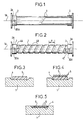
- Figure 1 is a schematic view partially cut from a laminated tube fitted with a pair of fittings constituting part of an electrical insulator.
- Figure 2 shows schematically the tube of the Figure 1 in which is arranged a helical groove for the passage of an optical waveguide.
- FIG. 3 schematically shows, in axial section, part of the tube of figure 2 with the groove in which is deposited the first strip of material elastomer.
- Figure 4 shows schematically the part of the tube of Figure 3 but with the optical waveguide deposited on the first strip of elastomeric material.
- Figure 5 shows schematically the part of the tube in Figure 4 but with the optical waveguide embedded in the elastomeric material.
- Figure 6 schematically shows the tube of the figure 2 once the optical waveguide is embedded in the elastomeric material.
- Figure 7 shows schematically the insulator electric with its final coating of elastomeric material constituting fins.
- the electrical insulator shown in Figure 7 has a laminated tube 1 visible in FIG. 1.
- This laminated tube 1 is obtained by winding fibers or mineral or organic yarns, such as fiberglass, on a mandrel not shown.
- the threads or fibers are agglomerated in layers successive with a curable synthetic resin.
- the tube 1 can take a cylindrical shape as shown in the Figure 1, frustoconical, bitronconic or other.
- the mandrel with the laminated tube 1 is brought to inside a heating oven to polymerize the synthetic resin. The whole is then taken out of the oven and the ends of the laminated tube 1 are cut off to obtain the desired axial length of the tube. This is the order of a few meters when the electrical insulator serves as a fixed support for a high voltage installation.
- the laminated tube 1 (especially when it comes of a cylindrical tube) on the mandrel can be cut off in several places to obtain several tubes laminates each having a desired axial length.
- the mandrel is then extracted from the laminated tube 1 (or laminated tubes obtained after cutting as indicated above).
- Two fittings 2 and 3 are inserted respectively at two ends of the tube and each sealed with a sticking agent on a surface of the tube.
- Each litter cylindrical came from machining the outer surface end of the tube.
- the two fittings have in their wall passages 2A and 3A shown schematically in the figures, which extend substantially parallel to axis 1A when the fittings are inserted on the tube. It is understood that each passage leads only to the outside of the tube.
- Laminated tube 1 fitted with two fittings 2 and 3 is mounted on a lathe not shown, the fittings being caught in the jaws of the lathe. It is machined by milling so as to form in the wall of the tube a groove 4B which winds helically around the longitudinal axis 1A of the tube.
- the ends of the groove 4B are in the following alignment axis 1A with openings 20A, 30A of passages 2A and 3A (openings placed on the middle side of the tube in the figure 2) in fittings, alignment being easily obtained by adjusting the pitch (constant or variable) of the winding of the groove 4B.
- groove helical 4B is advantageously extended to both ends respectively by two circular grooves 4A and 4C which are carried out near the inner edge of each fitting which is placed on the middle side of the tube. This arrangement makes it possible to dispense with the adjustment of the pitch P winding of the groove 4B whatever the position relative of the passages in the fittings.
- Laminated tube 1 with grooves 4A, 4B and 4C is shown in Figure 2.
- the grooves 4A, 4B and 4C are made on the "cylindrical" outer surface of the laminate tube.
- Each circular groove 4A and 4C is part of the span on which a fitting is inserted, this bearing having been machined before sealing the fittings on the tube as indicated above, which simplifies the manufacture of the electrical insulator.
- the thickness of the wall of the tube laminate is provided to meet the constraints mechanical required in the presence of grooves 4A to 4C.
- the the depth of the grooves 4A to 4C must also be sufficient to accommodate an optical waveguide such as a bundle of optical fibers 6 as described below.
- a strip 5 in elastomeric material with cross-section complementary to the cross-section of each groove 4A, 4B, 4C and obtained by extrusion, is deposited in the groove (s) 4A, 4B, 4C along this (s), by a helical winding, as shown in the figure 3.
- a bundle of optical fibers 6, of preferably in sheet, is threaded, by one of its ends in passage 20A, for example, of fitting 2. Then, there is deposited on top of the strip 5, by a winding helically, as shown in Figure 4. The other end of the bundle of optical fibers is then threaded into the passage 3A of the fitting 3.
- optical fibers 6 are then embedded in the inside of the strip 5 by crushing the assembly (optical fibers and tape) using a pressure roller which rolls along grooves 4A, 4B and 4C. Pressure exercised by the roller on the tube is possibly adjustable. In this way, the optical fibers 6 are pressed into the bottom of groove 4 (actually 4A, 4B and 4C) which is completely filled with elastomeric material 5 like shown in figure 5 so as to obtain a surface outside of the tube 1 which is uniform.
- Figure 6 shows the external appearance of the tube after the rolling operation with the optical fibers 6 which open at the two ends of the tube through fittings 2 and 3.
- the lathe on which is mounted the tube 1 rotates it around its axis 1A, it is advantageous to carry out at the same time the deposition of the optical fibers 6 on the strip 5 (by winding) and the crushing of these optical fibers and the tape so as to reduce the manufacturing time of the insulator.
- the laminated tube 1 of FIG. 6 equipped with the fibers optics 6 is then coated with an elastomeric material vulcanized, such as ethylene-propylene rubber or silicone, as described in patent application FR-2363170 so as to form a plurality of insulating fins 7 around tube 1 and get the electrical insulator shown at Figure 7.
- these fins are formed at from a continuous strip of the elastomeric material which is obtained by extrusion and which presents in section the shape an inverted T.
- the small transition of optical fibers from tube 1 (actually from a groove) to a fitting (actually in a passage such as 2A or 3A) is covered by the strip of elastomeric material which constitutes the insulating fins.
- the step of the groove can vary along the tube without that this hinders the placement of optical fibers in the groove and in fittings.
- the different electrical insulator manufacturing phases are well dissociated between them which simplifies the implementation of the process. It is understood, that after the crushing of the tape 6, the outer surface of the tube is uniform to obtain good adhesion to the strip's laminate tube constituting the insulating fins.
Abstract
Description
L'invention porte sur un isolateur électrique comprenant un élément support ayant une paroi extérieure qui s'étend suivant un axe longitudinal entre deux extrémités, deux ferrures scellées respectivement aux extrémités de l'élément support sur des portées formées dans la paroi extérieure de celui-ci et un guide d'onde optique qui est mis en place à l'intérieur de l'isolateur pour s'étendre d'une extrémité à l'autre de celui-ci et traverser les deux ferrures. Un tel isolateur est connu par le document JP 60-225 806An electrical insulator is provided comprising a support member having an outer wall which extends along a longitudinal axis between two ends, two fittings respectively sealed at the ends of the support element on spans formed in the wall exterior of it and an optical waveguide which is set up inside the insulator to extend from one end to the other of it and cross the two fittings. Such an insulator is known from document JP 60-225 806
Un isolateur électrique du genre indiqué ci-dessus est destiné en particulier pour servir d'organe support isolant à une installation extérieure haute tension comme décrit dans le document US-4802731.An electrical insulator of the type indicated above is intended in particular to serve as an insulating support member to a high voltage outdoor installation as described in document US-4802731.
Ce document divulgue une première disposition selon laquelle le guide d'onde optique est mis en place dans le volume intérieur de l'élément support constitué d'un tube stratifié, suivant un trajet linéaire ou même hélicoïdal. Toutefois, le volume intérieur du tube est généralement rempli d'un gaz diélectrique sous pression, comme du SF6, pour éviter les phénomènes d'amorçage d'arcs électriques entre l'extrémité de haut potentiel de l'isolateur et l'extrémité de bas potentiel de l'isolateur. Il s'ensuit que cette disposition du guide d'onde optique implique des problèmes d'étanchéité puisque le guide d'onde optique doit passer du volume intérieur du tube à l'extérieur du tube.This document discloses a first provision according to which the optical waveguide is placed in the internal volume of the support element consisting of a tube laminate, following a linear or even helical path. However, the internal volume of the tube is generally filled with a pressurized dielectric gas, such as SF6, to avoid arcing phenomena between the high potential end of the insulator and the low potential end of the insulator. It follows that this arrangement of the optical waveguide involves sealing problems since the optical waveguide must switch from the interior volume of the tube to the exterior of the tube.
Le document cité ci-dessus divulgue encore une disposition selon laquelle le guide d'onde optique est noyé dans l'épaisseur du tube stratifié. En fait il est proposé de combiner l'enroulement filamentaire pour la fabrication du tube stratifié avec un enroulement du guide d'onde optique. Un tel procédé s'avère en pratique très difficile à mettre en oeuvre notamment parce que le guide d'onde optique doit subir des contraintes tant mécaniques que thermiques lors de l'opération de chauffage du tube qui suit l'enroulement filamentaire. De plus, il s'avère difficile de maintenir une extrémité du guide d'onde optique alors qu'on procède à son enroulement, gérer le retournement de l'enroulement filamentaire en même temps que l'enroulement du guide d'onde optique. En plus, les extrémités du tube doivent être tronçonnées ce qui est délicat en présence du guide d'onde optique.The document cited above further discloses a arrangement that the optical waveguide is embedded in the thickness of the laminated tube. In fact it is proposed to combine filament winding for manufacturing laminated tube with a waveguide winding optical. Such a method proves in practice very difficult to implement in particular because the optical waveguide must undergo both mechanical and thermal stresses during the following tube heating operation filament winding. In addition, it is difficult to hold one end of the optical waveguide while rolls it up, manage the flipping of the filament winding at the same time as the winding of the optical waveguide. In addition, the ends of the tube must be cut which is difficult in the presence of the optical waveguide.
Le document cité ci-dessus propose encore de noyer le guide d'onde optique dans le matériau élastomère qui revêt le tube stratifié et qui constitue les ailettes isolantes. Mais là encore, un tel procédé s'avère très difficile à mettre en oeuvre quand les ailettes de l'isolateur sont constituées par une bande continue en matériau élastomère obtenue par extrusion et qui est enroulée en hélice autour du tube. De plus, ce procédé implique que le pas d'enroulement du guide d'onde optique autour du tube soit identique au pas d'enroulement de la bande continue extrudée qui constitue les ailettes. Or il s'avère nécessaire de pouvoir faire varier la longueur du guide d'onde entre les deux extrémités du tube indépendamment du nombre d'ailettes pour adapter le gradient de la tension électrique admissible qui est établie dans le guide d'onde optique.The document cited above also proposes to drown the optical waveguide in the coated elastomeric material the laminated tube which constitutes the insulating fins. But here again, such a process proves to be very difficult to use when the fins of the insulator are formed by a continuous strip of elastomeric material obtained by extrusion and which is wound in a helix around of the tube. In addition, this process implies that the step winding the optical waveguide around the tube either identical to the winding pitch of the extruded continuous strip which constitutes the fins. However, it is necessary to ability to vary length of waveguide between two ends of the tube regardless of the number of fins to adapt the gradient of the admissible electrical voltage which is established in the optical waveguide.
Le but de l'invention est de proposer un isolateur électrique qui ne présente pas les inconvénients indiqués ci-dessus et qui est simple à réaliser ainsi qu'un procédé de fabrication d'un tel isolateur.The object of the invention is to propose an isolator electric which does not have the disadvantages indicated above and which is simple to carry out as well as a process manufacturing such an insulator.
Selon l'invention, le guide d'onde optique s'étend dans le fond d'une rainure hélicoïdale et de deux rainures circulaires s'enroulant autour de l'axe longitudinal de l'élément support, par exemple un tube stratifié. Les rainures sont formées dans la paroi extérieure de l'élément support. Chaque rainure circulaire prolonge une des extrémités de la rainure hélicoïdale et fait partie d'une portée sur laquelle est scellée la ferrure correspondante. Le guide d'onde optique est noyé dans le matériau élastomère qui remplit ces rainures. Pour fabriquer cet isolateur, on usine l'élément support pour former les portées des ferrures qui définissent aussi les rainures circulaires. Après le scellement des ferrures; on usine l'élément support pour former la rainure hélicoïdale. Ensuite, une bande continue en matériau élastomère est mise en place dans les rainures. Puis le guide d'onde optique est déposé sur le dessus et le long de cette bande continue. Enfin, on exerce une pression sur le dessus de la bande continue de sorte à noyer le guide d'onde optique dans le matériau élastomère au fond des rainures.According to the invention, the optical waveguide extends in the bottom of a helical groove and two grooves circular wrapping around the longitudinal axis of the support element, for example a laminated tube. The grooves are formed in the outer wall of the element support. Each circular groove extends one of the ends of the helical groove and is part of a bearing surface on which the corresponding fitting is sealed. The optical waveguide is embedded in the elastomeric material which fills these grooves. To make this isolator, we machines the support element to form the bearing surfaces of the fittings which also define the circular grooves. After the sealing of fittings; the support element is machined for form the helical groove. Then a continuous strip made of elastomeric material is placed in the grooves. Then the optical waveguide is placed on top and the along this continuous strip. Finally, there is pressure on the top of the strip continues so as to drown the guide optical wave in the elastomeric material at the bottom of the grooves.
Cette disposition assure un positionnement stable du guide d'onde. Il est possible de mettre en place un guide d'onde optique constitué d'un grand nombre de fibres optiques.This arrangement ensures stable positioning of the waveguide. It is possible to set up a guide optical wave consisting of a large number of fibers optics.
Un mode de réalisation de l'invention est décrit ci-dessous en référence aux dessins annexés.An embodiment of the invention is described below with reference to the accompanying drawings.
La figure 1 est une vue schématique partiellement coupée d'un tube stratifié équipé d'une paire de ferrures constituant une partie d'un isolateur électrique.Figure 1 is a schematic view partially cut from a laminated tube fitted with a pair of fittings constituting part of an electrical insulator.
La figure 2 montre schématiquement le tube de la figure 1 dans lequel est aménagée une rainure hélicoïdale pour le passage d'un guide d'onde optique.Figure 2 shows schematically the tube of the Figure 1 in which is arranged a helical groove for the passage of an optical waveguide.
La figure 3 montre schématiquement, en coupe axiale, une partie du tube de la figure 2 avec la rainure dans laquelle est déposée la première bande en matériau élastomère.FIG. 3 schematically shows, in axial section, part of the tube of figure 2 with the groove in which is deposited the first strip of material elastomer.
La figure 4 montre schématiquement la partie du tube de la figure 3 mais avec le guide d'onde optique déposé sur la première bande en matériau élastomère.Figure 4 shows schematically the part of the tube of Figure 3 but with the optical waveguide deposited on the first strip of elastomeric material.
La figure 5 montre schématiquement la partie du tube de la figure 4 mais avec le guide d'onde optique noyé dans le matériau élastomère.Figure 5 shows schematically the part of the tube in Figure 4 but with the optical waveguide embedded in the elastomeric material.
La figure 6 montre schématiquement le tube de la figure 2 une fois que le guide d'onde optique est noyé dans le matériau élastomère. Figure 6 schematically shows the tube of the figure 2 once the optical waveguide is embedded in the elastomeric material.
La figure 7 montre schématiquement l'isolateur électrique avec son revêtement final en matériau élastomère constituant des ailettes.Figure 7 shows schematically the insulator electric with its final coating of elastomeric material constituting fins.
L'isolateur électrique montré à la figure 7 comporte
un tube stratifié 1 visible à la figure 1.
Ce tube stratifié 1 est obtenu par enroulement de fibres ou
fils minéraux ou organiques, comme la fibre de verre, sur un
mandrin non représenté.The electrical insulator shown in Figure 7 has
a laminated
Les fils ou fibres sont agglomérées en couches
successives par une résine synthétique durcissable. Le tube
1 peut prendre une forme cylindrique comme montrée à la
figure 1, tronconique, bitronconique ou autre.The threads or fibers are agglomerated in layers
successive with a curable synthetic resin. The
Le mandrin avec le tube stratifié 1 est amené à
l'intérieur d'une étuve chauffante pour polymériser la
résine synthétique. L'ensemble est ensuite sorti de l'étuve
et les extrémités du tube stratifié 1 sont tronçonnées pour
obtenir la longueur axiale voulue du tube. Celle-ci est de
l'ordre de quelques mètres lorsque l'isolateur électrique
sert de support fixe à une installation à haute tension. A
noter que le tube stratifié 1 (notamment quand il s'agit
d'une tube cylindrique) sur le mandrin peut être tronçonné
en plusieurs endroits pour obtenir plusieurs tubes
stratifiés ayant chacun une longueur axiale voulue.The mandrel with the laminated
Le mandrin est ensuite extrait du tube stratifié 1 (ou des tubes stratifiés obtenus après tronçonnage comme indiqué ci-dessus).The mandrel is then extracted from the laminated tube 1 (or laminated tubes obtained after cutting as indicated above).
Deux ferrures 2 et 3 sont insérées respectivement aux
deux extrémités du tube et scellées chacune à l'aide d'un
agent collant sur une portée du tube. Chaque portée
cylindrique est venue d'usinage de la surface extérieure
d'extrémité du tube. A noter que les deux ferrures
présentent dans leur paroi respectivement des passages 2A et
3A représentés de façon schématique sur les figures, qui
s'étendent sensiblement parallèlement à l'axe 1A quand les
ferrures sont insérées sur le tube. Il est entendu que
chaque passage débouche uniquement vers l'extérieur du tube. Two
Le tube stratifié 1 équipé des deux ferrures 2 et 3
est monté sur un tour non représenté, les ferrures étant
prises dans les mors du tour. Il est usiné par fraisage de
manière à former dans la paroi du tube une rainure 4B qui
s'enroule en hélice autour de l'axe longitudinal 1A du tube.
Les extrémités de la rainure 4B sont en alignement suivant
l'axe 1A avec les ouvertures 20A,30A des passages 2A et 3A
(ouvertures placées du côté du milieu du tube sur la figure
2) dans les ferrures, l'alignement étant obtenu facilement
par un réglage du pas (constant ou variable) de
l'enroulement de la rainure 4B. A noter que la rainure
hélicoïdale 4B est avantageusement prolongée à ses deux
extrémités respectivement par deux rainures circulaires 4A
et 4C qui sont réalisées à proximité du bord intérieur de
chaque ferrure qui est placé du côté du milieu du tube.
cette disposition permet de s'affranchir du réglage du pas P
d'enroulement de la rainure 4B quelque que soit la position
relative des passages dans les ferrures. Le tube stratifié 1
avec les rainures 4A,4B et 4C est montré à la figure 2. A
noter encore que les rainures 4A,4B et 4C sont réalisées sur
la surface extérieure "cylindrique" du tube stratifié.
Chaque rainure circulaire 4A et 4C fait partie de la portée
sur laquelle est insérée une ferrure, cette portée ayant été
usinée avant le scellement des ferrures sur le tube comme
indiqué plus haut, ce qui simplifie la fabrication de
l'isolateur électrique.Laminated
Il est entendu que l'épaisseur de la paroi du tube
stratifiée est prévue de façon à tenir les contraintes
mécaniques requises en présence des rainures 4A à 4C. La
profondeur des rainures 4A à 4C doit en outre être
suffisante pour accueillir un guide d'onde optique tel qu'un
faisceau de fibres optiques 6 comme décrit par la suite.It is understood that the thickness of the wall of the tube
laminate is provided to meet the constraints
mechanical required in the presence of grooves 4A to 4C. The
the depth of the grooves 4A to 4C must also be
sufficient to accommodate an optical waveguide such as a
bundle of
Après réalisation de la rainure 4B, une bande 5 en
matériau élastomère, à section complémentaire à la section
de chaque rainure 4A,4B,4C et obtenue par extrusion, est
déposée dans la ou les rainures 4A,4B,4C le long de
celle(s)-ci, par un enroulement en hélice, comme montré à la
figure 3.After completion of the groove 4B, a
Ensuite, un faisceau de fibres optiques 6, de
préférence en nappe, est enfilé, par une de ses extrémités
dans le passage 20A, par exemple, de la ferrure 2. Puis, il
est déposé sur le dessus de la bande 5, par un enroulement
en hélice, comme montré à la figure 4. L'autre extrémité du
faisceau de fibres optiques est ensuite enfilée dans le
passage 3A de la ferrure 3.Next, a bundle of
Les fibres optiques 6 sont ensuite noyées à
l'intérieur de la bande 5 par écrasement de l'ensemble
(fibres optiques et bande) à l'aide d'un galet de pression
qui roule le long des rainures 4A,4B et 4C. La pression
exercée par le galet sur le tube est éventuellement
réglable. De cette façon, les fibres optiques 6 sont
plaquées dans le fond de la rainure 4 (en fait 4A,4B et 4C)
qui est remplie complètement du matériau élastomère 5 comme
montré à la figure 5 de sorte à obtenir une surface
extérieure du tube 1 qui soit uniforme. La figure 6 montre
l'aspect extérieur du tube après l'opération de roulage avec
les fibres optiques 6 qui débouchent aux deux extrémités du
tube au travers des ferrures 2 et 3. A noter que si le tour
sur lequel est monté le tube 1 entraíne en rotation celui-ci
autour de son axe 1A, il est avantageux de réaliser en même
temps le dépôt des fibres optiques 6 sur la bande 5 (par
enroulement) et l'écrasement de ces fibres optiques et de la
bande de sorte à réduire le temps de fabrication de
l'isolateur.The
Le tube stratifié 1 de la figure 6 équipé des fibres
optiques 6 est ensuite revêtu d'un matériau élastomère
vulcanisé, tel qu'un caoutchouc éthylène-propylène ou un
silicone, comme décrit dans la demande de brevet FR-2363170
de façon à former une pluralité d'ailettes isolantes 7
autour du tube 1 et obtenir l'isolateur électrique montré à
la figure 7. En particulier, ces ailettes sont constituées à
partir d'une bande continue du matériau élastomère qui est
obtenue par extrusion et qui présente en section la forme
d'un T renversé. La petite transition des fibres optiques
depuis le tube 1 (en fait depuis une rainure) vers un
ferrure (en fait dans un passage tel que 2A ou 3A) est
recouverte par la bande en matériau élastomère qui constitue
les ailettes isolantes.The
Dans le procédé qui vient d'être décrit, le pas
d'enroulement de la rainure peut varier le long du tube sans
que cela gène la mise en place des fibres optiques dans la
rainure et dans les ferrures. De plus, les différentes
phases de la fabrication de l'isolateur électrique sont bien
dissociées entre elles ce qui simplifie la mise en oeuvre du
procédé. Il est entendu, qu'après l'écrasement de la bande
6, la surface extérieure du tube est uniforme pour obtenir
une bonne adhérisation sur le tube stratifié de la bande
constituant les ailettes isolantes.In the process which has just been described, the step
of the groove can vary along the tube without
that this hinders the placement of optical fibers in the
groove and in fittings. In addition, the different
electrical insulator manufacturing phases are well
dissociated between them which simplifies the implementation of the
process. It is understood, that after the crushing of the
Claims (7)
- Electrical isolator comprising a support member (1) having an outer wall which extends along a longitudinal axis (1A) between two ends, two fittings (2,3) which are bedded into respective ends of the support member on bearing surfaces formed in the outer wall thereof, and an optical waveguide (6) which is positioned within the isolator to extend from one end to the other thereof and to pass through the two fittings, characterised in that said optical waveguide is housed on the one hand in two circular grooves (4A,4C) which are formed in the outer wall of the support member and which form part of respective ones of the bearing surfaces for the fittings, and on the other hand in a helical groove (4B) which is formed in the outer wall of the support member and which has ends which open into respective ones of the two circular grooves (4A,4C).
- Isolator according to claim 1 in which the support member (1) is surrounded by a coating of elastomeric material forming a plurality of annular vanes (7), said grooves (4A,4B,4C) formed in the outer wall of the support member being filled with said elastomeric material and said optical waveguide (6) being embedded in said elastomeric material which fills said grooves.
- Isolator according to claim 1 in which said helical groove (4B) circles round the longitudinal axis (1A) at a pitch which varies along the axis.
- Method of producing an electrical isolator comprising a support member (1) having an outer wall which extends along a longitudinal axis (1A) between two ends, two fittings (2,3) which are bedded into respective ends of the support member on bearing surfaces formed in the outer wall thereof, and at least one optical waveguide (6) which is positioned within the isolator to extend from one end to the other thereof and to pass through the two fittings, characterised by the following steps:machining of the support member (1) to form, in the outer wall thereof, a helical groove (4B) which circles in helical fashion around said longitudinal axis (1A),fitting of a continuous extruded strip (5) of elastomeric material into and along said helical groove (4B),laying down of the optical waveguide (6) on the top of the strip (5) and along said helical groove,a pressure being exerted on the top of the strip (5) to set the optical waveguide into the bottom of said helical groove and embed it in the elastomeric material.
- Method according to claim 4, also comprising the stage consisting of machining the support member (1) to form, in the outer wall thereof, two bearing surfaces for bedding in the fittings in such a way as to form, after the fittings have been bedded in on said bearing surfaces, two circular grooves (4A,4C) which circle around said longitudinal axis (1A), each circular groove being positioned close to the edge of a fitting.
- Method according to claim 4, in which the stage of laying down the optical waveguide (6) on the top of the strip of elastomeric material (5) and the stage in which a pressure is exerted on the top of the strip (5) are carried out at the same time.
- Method according to claim 6, in which the support member is driven in rotation about said longitudinal axis (1A) during the stage of laying down said strip of elastomeric material (5) and the stage in which a pressure is exerted on the top of the strip.
Applications Claiming Priority (2)
| Application Number | Priority Date | Filing Date | Title |
|---|---|---|---|
| FR9411726 | 1994-09-30 | ||
| FR9411726A FR2725302B1 (en) | 1994-09-30 | 1994-09-30 | AN ELECTRICAL ISOLATOR EQUIPPED WITH OPTICAL FIBERS AND ITS MANUFACTURING METHOD |
Publications (2)
| Publication Number | Publication Date |
|---|---|
| EP0704735A1 EP0704735A1 (en) | 1996-04-03 |
| EP0704735B1 true EP0704735B1 (en) | 2002-04-17 |
Family
ID=9467469
Family Applications (1)
| Application Number | Title | Priority Date | Filing Date |
|---|---|---|---|
| EP95402166A Expired - Lifetime EP0704735B1 (en) | 1994-09-30 | 1995-09-27 | Electrical insulator with optical fibres and manufacturing process |
Country Status (12)
| Country | Link |
|---|---|
| US (1) | US5594827A (en) |
| EP (1) | EP0704735B1 (en) |
| JP (1) | JP3410879B2 (en) |
| KR (1) | KR100348544B1 (en) |
| AT (1) | ATE216504T1 (en) |
| BR (1) | BR9504237A (en) |
| CA (1) | CA2159573C (en) |
| DE (1) | DE69526400T2 (en) |
| DK (1) | DK0704735T3 (en) |
| ES (1) | ES2172565T3 (en) |
| FR (1) | FR2725302B1 (en) |
| ZA (1) | ZA958233B (en) |
Families Citing this family (26)
| Publication number | Priority date | Publication date | Assignee | Title |
|---|---|---|---|---|
| FR2727561B1 (en) * | 1994-11-30 | 1996-12-20 | Sediver | ELECTRICAL INSULATOR, METHOD FOR MANUFACTURING SUCH AN INSULATOR, AND DEVICE FOR IMPLEMENTING THE METHOD |
| DE19633695C1 (en) * | 1996-08-21 | 1998-04-02 | Reinhausen Maschf Scheubeck | Process for producing a wound insulating tube III |
| DE19635362C1 (en) * | 1996-08-21 | 1997-12-04 | Siemens Ag | Making e.g. high voltage, glass fibre-reinforced epoxy insulators incorporating optical fibre channel |
| DE19635372C1 (en) | 1996-08-21 | 1997-10-09 | Siemens Ag | Wound high voltage insulating tube |
| EP0926516A4 (en) * | 1997-07-03 | 2000-07-19 | Ngk Insulators Ltd | Organic insulating device with built-in optical fiber and manufacturing method therefor |
| US6215940B1 (en) * | 1998-06-01 | 2001-04-10 | 3M Innovative Properties Company | High voltage insulator for optical fibers |
| SE513494C2 (en) * | 1999-04-01 | 2000-09-18 | Daimler Chrysler Ag | Wheel axle guard |
| WO2002052304A2 (en) * | 2000-12-22 | 2002-07-04 | Corning Incorporated | Fiber optic spools and methods of making the same |
| CA2349253C (en) * | 2000-12-26 | 2009-11-17 | S&C Electric Company | Method and arrangement for providing a gas-tight housing joint |
| US6952154B2 (en) * | 2002-06-16 | 2005-10-04 | Maclean-Fogg Company | Composite insulator for fuse cutout |
| US6831232B2 (en) * | 2002-06-16 | 2004-12-14 | Scott Henricks | Composite insulator |
| US6776522B2 (en) | 2002-10-09 | 2004-08-17 | Steven J. Syracuse | Apparatus and system for monitoring temperature of high voltage conductors |
| EP1418452A1 (en) * | 2002-11-07 | 2004-05-12 | Abb Research Ltd. | High voltage device with optical fiber and fabrication method therefor |
| US6897380B2 (en) | 2002-11-29 | 2005-05-24 | Sumitomo Wiring Systems, Ltd. | Grommet for a wire harness |
| KR100699222B1 (en) | 2005-01-14 | 2007-03-27 | 엘에스전선 주식회사 | Composite insulator manufacture method for high voltage |
| WO2007010025A1 (en) * | 2005-07-20 | 2007-01-25 | Areva T & D Sa | Electric insulator and a method for the production thereof |
| US8579886B2 (en) * | 2007-05-01 | 2013-11-12 | Covidien Lp | Accordion style cable stand-off |
| FR2941811A1 (en) * | 2009-01-30 | 2010-08-06 | Areva T & D Sa | Electric insulator for e.g. non-conventional instrument transformer, has optical fibers placed along external surface of body, and insulated material cover surrounding body, where optical fibers are housed in cured epoxy resin protection |
| IT1398519B1 (en) * | 2009-09-29 | 2013-03-01 | Eni Spa | METHOD OF INSTALLATION OF LONG-DUCT FIBER OPTIC SENSORS USED IN FLUID TRANSPORT |
| US8774587B1 (en) | 2013-01-26 | 2014-07-08 | Optisense Network, Llc | Stress control structure for optical fibers in a high voltage environment |
| KR101641652B1 (en) * | 2013-02-12 | 2016-07-21 | 포리프라스틱 가부시키가이샤 | Grooved resin molded part |
| US9347973B2 (en) | 2013-05-15 | 2016-05-24 | Gridview Optical Solutions, Llc | Stress control assembly and methods of making the same |
| KR101734344B1 (en) | 2014-03-25 | 2017-05-11 | 포리프라스틱 가부시키가이샤 | Composite molded article and method for manufacturing same |
| CN106772844A (en) * | 2015-11-24 | 2017-05-31 | 泰科电子(上海)有限公司 | Insulator and its manufacture method |
| KR102047376B1 (en) * | 2019-04-01 | 2019-11-21 | 주식회사 웰코 | tunnel bracket and manufacturing method at the same |
| DE102021130320A1 (en) * | 2021-11-19 | 2023-05-25 | Maschinenfabrik Reinhausen Gmbh | PROCESS FOR MAKING A HIGH VOLTAGE INSULATOR AND HIGH VOLTAGE INSULATOR |
Family Cites Families (13)
| Publication number | Priority date | Publication date | Assignee | Title |
|---|---|---|---|---|
| AU568618B2 (en) * | 1982-12-13 | 1988-01-07 | Afl Telecommunications Europe Limited | Fibre optic cable arrangement |
| JPS60225806A (en) * | 1984-04-24 | 1985-11-11 | Fujikura Ltd | Composite insulator for optical fiber |
| JPS60262103A (en) * | 1984-06-08 | 1985-12-25 | Tokyo Electric Power Co Inc:The | Insulator for incorporating optical fiber |
| DE8421520U1 (en) * | 1984-07-18 | 1986-11-13 | Siemens Ag, 1000 Berlin Und 8000 Muenchen, De | |
| GB8424584D0 (en) * | 1984-09-28 | 1984-11-07 | Bicc Plc | Overhead electric and optical transmission system |
| GB8428575D0 (en) * | 1984-11-12 | 1984-12-19 | Raychem Ltd | Electrical insulator |
| US4610033A (en) * | 1984-12-14 | 1986-09-02 | Harvey Hubbell Incorporated | Insulator with fiber optic communication channel |
| CH671639A5 (en) * | 1986-10-24 | 1989-09-15 | Bbc Brown Boveri & Cie | |
| JPH01246724A (en) * | 1988-03-28 | 1989-10-02 | Ngk Insulators Ltd | Optical-fiber complex insulator and its manufacture |
| DE68922815T2 (en) * | 1988-10-14 | 1995-12-14 | Ngk Insulators Ltd | Composite isolator of the type with built-in optical fiber and method of manufacturing the same. |
| DE8914972U1 (en) * | 1989-12-21 | 1990-03-08 | Felten & Guilleaume Energietechnik Ag, 5000 Koeln, De | |
| DE4227410C1 (en) * | 1992-08-19 | 1993-11-04 | Felten & Guilleaume Energie | Overhead line termination for optical fibre phase cable - has tubular ceramics isolator fitted with internal plastics reinforced sleeve filled with foamed elastomer material |
| JPH06325648A (en) * | 1993-05-14 | 1994-11-25 | Furukawa Electric Co Ltd:The | Insulator wire built-in optical fiber |
-
1994
- 1994-09-30 FR FR9411726A patent/FR2725302B1/en not_active Expired - Fee Related
-
1995
- 1995-09-27 ES ES95402166T patent/ES2172565T3/en not_active Expired - Lifetime
- 1995-09-27 DE DE69526400T patent/DE69526400T2/en not_active Expired - Lifetime
- 1995-09-27 AT AT95402166T patent/ATE216504T1/en active
- 1995-09-27 EP EP95402166A patent/EP0704735B1/en not_active Expired - Lifetime
- 1995-09-27 DK DK95402166T patent/DK0704735T3/en active
- 1995-09-29 KR KR1019950032758A patent/KR100348544B1/en not_active IP Right Cessation
- 1995-09-29 ZA ZA958233A patent/ZA958233B/en unknown
- 1995-09-29 US US08/536,476 patent/US5594827A/en not_active Expired - Lifetime
- 1995-09-29 CA CA002159573A patent/CA2159573C/en not_active Expired - Fee Related
- 1995-09-29 BR BR9504237A patent/BR9504237A/en not_active IP Right Cessation
- 1995-09-29 JP JP25361695A patent/JP3410879B2/en not_active Expired - Lifetime
Also Published As
| Publication number | Publication date |
|---|---|
| CA2159573A1 (en) | 1996-03-31 |
| JP3410879B2 (en) | 2003-05-26 |
| DE69526400D1 (en) | 2002-05-23 |
| KR100348544B1 (en) | 2002-11-23 |
| EP0704735A1 (en) | 1996-04-03 |
| CA2159573C (en) | 2006-08-29 |
| KR960012043A (en) | 1996-04-20 |
| JPH08212856A (en) | 1996-08-20 |
| ZA958233B (en) | 1996-04-24 |
| ATE216504T1 (en) | 2002-05-15 |
| US5594827A (en) | 1997-01-14 |
| BR9504237A (en) | 1996-07-30 |
| ES2172565T3 (en) | 2002-10-01 |
| FR2725302B1 (en) | 1997-03-14 |
| DK0704735T3 (en) | 2002-07-01 |
| DE69526400T2 (en) | 2003-02-13 |
| FR2725302A1 (en) | 1996-04-05 |
Similar Documents
| Publication | Publication Date | Title |
|---|---|---|
| EP0704735B1 (en) | Electrical insulator with optical fibres and manufacturing process | |
| EP0204607B1 (en) | Mast made from plastic material for supporting especially electric wires, and device for winding fibres around this mast | |
| CA1253223A (en) | Electrical cable for the transportation of very high currents at low voltages, and its manufacture | |
| CA1137284A (en) | Manufacture of an insulating element with a finned core, and element so made | |
| FR2655765A1 (en) | CABLE FOR AERIAL ELECTRIC POWER TRANSPORT LINE, AND METHODS AND DEVICES FOR MANUFACTURING SUCH A CABLE. | |
| WO1997039462A1 (en) | Enhanced varistor-based lighting arresters | |
| FR2723645A1 (en) | PROCESS FOR MANUFACTURING A REINFORCED FIBER OPTIC CABLE, DEVICE FOR IMPLEMENTING THIS PROCESS AND CABLE OBTAINED BY THIS PROCESS | |
| EP0204608A1 (en) | Cable support for a utility pole | |
| EP0716426B1 (en) | Process of manufacturing an electrical insulator | |
| FR2503476A1 (en) | Fitting protective sheath over electric cable - using cylindrical mandrel to carry sheath which is rolled forward over bared cable end | |
| EP0720181A1 (en) | Electrical insulator, manufacturing method of such an insulator and device for carrying out the method | |
| EP0019026A1 (en) | Carrier element for the realisation of unitary fibre optics cable elements and manufacturing process | |
| FR2508180A1 (en) | OPTICAL FIBER CABLE AND METHOD FOR MANUFACTURING THE SAME | |
| EP0518738B1 (en) | Method of realizing a loose tube fibre cable and resulting cable | |
| FR2511161A1 (en) | OPTICAL CABLE FOR SUPPORTING HIGH PRESSURES | |
| EP0379853A1 (en) | Electrical cable for high tensions | |
| FR2735511A1 (en) | MULTI-LAYERED CABLE SHEATH, MANUFACTURING METHOD THEREOF, AND MACHINE FOR CARRYING OUT SAID METHOD | |
| FR2501382A1 (en) | CABLE ELEMENT AND OPTICAL FIBER CABLE, PARTICULARLY CAPABLE OF RESISTING HIGH TRACTIONS AND / OR PRESSURES, AND METHOD FOR MANUFACTURING THE SAME | |
| EP3711915A1 (en) | Method and facility for manufacturing a rotating part made of a composite material | |
| EP0015816B1 (en) | Method of manufacturing a coaxial cable | |
| WO1996004666A1 (en) | Cable for conveying electrical energy or telecommunications and method for the manufacture of such a cable | |
| FR2570510A1 (en) | METHOD FOR MANUFACTURING AN OPTICAL FIBER CABLE, AND CABLE OBTAINED BY ITS IMPLEMENTATION | |
| EP0141723A2 (en) | Production method for a fibre-optical cable without any electrically conducting materials | |
| FR2500204A1 (en) | PERFECTED ELECTRIC CABLES, AND METHODS AND APPARATUS FOR THE PRODUCTION OF SUCH CABLES | |
| EP0419338A1 (en) | Thermal protection skin, a method and a production installation |
Legal Events
| Date | Code | Title | Description |
|---|---|---|---|
| PUAI | Public reference made under article 153(3) epc to a published international application that has entered the european phase |
Free format text: ORIGINAL CODE: 0009012 |
|
| AK | Designated contracting states |
Kind code of ref document: A1 Designated state(s): AT BE CH DE DK ES FR GB IT LI |
|
| 17P | Request for examination filed |
Effective date: 19960923 |
|
| GRAG | Despatch of communication of intention to grant |
Free format text: ORIGINAL CODE: EPIDOS AGRA |
|
| 17Q | First examination report despatched |
Effective date: 20010710 |
|
| GRAG | Despatch of communication of intention to grant |
Free format text: ORIGINAL CODE: EPIDOS AGRA |
|
| GRAH | Despatch of communication of intention to grant a patent |
Free format text: ORIGINAL CODE: EPIDOS IGRA |
|
| GRAH | Despatch of communication of intention to grant a patent |
Free format text: ORIGINAL CODE: EPIDOS IGRA |
|
| REG | Reference to a national code |
Ref country code: GB Ref legal event code: IF02 |
|
| GRAA | (expected) grant |
Free format text: ORIGINAL CODE: 0009210 |
|
| AK | Designated contracting states |
Kind code of ref document: B1 Designated state(s): AT BE CH DE DK ES FR GB IT LI |
|
| REF | Corresponds to: |
Ref document number: 216504 Country of ref document: AT Date of ref document: 20020515 Kind code of ref document: T |
|
| REG | Reference to a national code |
Ref country code: CH Ref legal event code: EP |
|
| REF | Corresponds to: |
Ref document number: 69526400 Country of ref document: DE Date of ref document: 20020523 |
|
| REG | Reference to a national code |
Ref country code: CH Ref legal event code: NV Representative=s name: ALTHOFF PATENTANWALTSBUERO |
|
| REG | Reference to a national code |
Ref country code: DK Ref legal event code: T3 |
|
| GBT | Gb: translation of ep patent filed (gb section 77(6)(a)/1977) |
Effective date: 20020701 |
|
| REG | Reference to a national code |
Ref country code: ES Ref legal event code: FG2A Ref document number: 2172565 Country of ref document: ES Kind code of ref document: T3 |
|
| PLBE | No opposition filed within time limit |
Free format text: ORIGINAL CODE: 0009261 |
|
| STAA | Information on the status of an ep patent application or granted ep patent |
Free format text: STATUS: NO OPPOSITION FILED WITHIN TIME LIMIT |
|
| 26N | No opposition filed |
Effective date: 20030120 |
|
| PGFP | Annual fee paid to national office [announced via postgrant information from national office to epo] |
Ref country code: DK Payment date: 20110926 Year of fee payment: 17 Ref country code: CH Payment date: 20110923 Year of fee payment: 17 |
|
| PGFP | Annual fee paid to national office [announced via postgrant information from national office to epo] |
Ref country code: GB Payment date: 20120920 Year of fee payment: 18 |
|
| PGFP | Annual fee paid to national office [announced via postgrant information from national office to epo] |
Ref country code: DE Payment date: 20120921 Year of fee payment: 18 Ref country code: ES Payment date: 20120926 Year of fee payment: 18 |
|
| PGFP | Annual fee paid to national office [announced via postgrant information from national office to epo] |
Ref country code: BE Payment date: 20120920 Year of fee payment: 18 Ref country code: FR Payment date: 20121017 Year of fee payment: 18 |
|
| PGFP | Annual fee paid to national office [announced via postgrant information from national office to epo] |
Ref country code: IT Payment date: 20120926 Year of fee payment: 18 |
|
| PGFP | Annual fee paid to national office [announced via postgrant information from national office to epo] |
Ref country code: AT Payment date: 20120912 Year of fee payment: 18 |
|
| BERE | Be: lapsed |
Owner name: SOC. EUROPEENNE D'ISOLATEURS EN VERRE ET COMPOSITE Effective date: 20130930 |
|
| REG | Reference to a national code |
Ref country code: CH Ref legal event code: PL |
|
| REG | Reference to a national code |
Ref country code: DK Ref legal event code: EBP Effective date: 20130930 |
|
| REG | Reference to a national code |
Ref country code: AT Ref legal event code: MM01 Ref document number: 216504 Country of ref document: AT Kind code of ref document: T Effective date: 20130927 |
|
| GBPC | Gb: european patent ceased through non-payment of renewal fee |
Effective date: 20130927 |
|
| REG | Reference to a national code |
Ref country code: FR Ref legal event code: ST Effective date: 20140530 |
|
| REG | Reference to a national code |
Ref country code: DE Ref legal event code: R119 Ref document number: 69526400 Country of ref document: DE Effective date: 20140401 |
|
| PG25 | Lapsed in a contracting state [announced via postgrant information from national office to epo] |
Ref country code: CH Free format text: LAPSE BECAUSE OF NON-PAYMENT OF DUE FEES Effective date: 20130930 Ref country code: GB Free format text: LAPSE BECAUSE OF NON-PAYMENT OF DUE FEES Effective date: 20130927 Ref country code: BE Free format text: LAPSE BECAUSE OF NON-PAYMENT OF DUE FEES Effective date: 20130930 Ref country code: LI Free format text: LAPSE BECAUSE OF NON-PAYMENT OF DUE FEES Effective date: 20130930 |
|
| PG25 | Lapsed in a contracting state [announced via postgrant information from national office to epo] |
Ref country code: FR Free format text: LAPSE BECAUSE OF NON-PAYMENT OF DUE FEES Effective date: 20130930 Ref country code: AT Free format text: LAPSE BECAUSE OF NON-PAYMENT OF DUE FEES Effective date: 20130927 Ref country code: DE Free format text: LAPSE BECAUSE OF FAILURE TO SUBMIT A TRANSLATION OF THE DESCRIPTION OR TO PAY THE FEE WITHIN THE PRESCRIBED TIME-LIMIT Effective date: 20140401 Ref country code: IT Free format text: LAPSE BECAUSE OF NON-PAYMENT OF DUE FEES Effective date: 20130927 |
|
| REG | Reference to a national code |
Ref country code: ES Ref legal event code: FD2A Effective date: 20141007 |
|
| PG25 | Lapsed in a contracting state [announced via postgrant information from national office to epo] |
Ref country code: DK Free format text: LAPSE BECAUSE OF NON-PAYMENT OF DUE FEES Effective date: 20130930 |
|
| PG25 | Lapsed in a contracting state [announced via postgrant information from national office to epo] |
Ref country code: ES Free format text: LAPSE BECAUSE OF NON-PAYMENT OF DUE FEES Effective date: 20130928 |