EP0703852B1 - Cable saw machine for cutting concrete bodies, walls, rocks or the like - Google Patents
Cable saw machine for cutting concrete bodies, walls, rocks or the like Download PDFInfo
- Publication number
- EP0703852B1 EP0703852B1 EP94926760A EP94926760A EP0703852B1 EP 0703852 B1 EP0703852 B1 EP 0703852B1 EP 94926760 A EP94926760 A EP 94926760A EP 94926760 A EP94926760 A EP 94926760A EP 0703852 B1 EP0703852 B1 EP 0703852B1
- Authority
- EP
- European Patent Office
- Prior art keywords
- rope
- pulleys
- saw
- frame
- pulley
- Prior art date
- Legal status (The legal status is an assumption and is not a legal conclusion. Google has not performed a legal analysis and makes no representation as to the accuracy of the status listed.)
- Expired - Lifetime
Links
Images


Classifications
-
- B—PERFORMING OPERATIONS; TRANSPORTING
- B28—WORKING CEMENT, CLAY, OR STONE
- B28D—WORKING STONE OR STONE-LIKE MATERIALS
- B28D1/00—Working stone or stone-like materials, e.g. brick, concrete or glass, not provided for elsewhere; Machines, devices, tools therefor
- B28D1/02—Working stone or stone-like materials, e.g. brick, concrete or glass, not provided for elsewhere; Machines, devices, tools therefor by sawing
- B28D1/08—Working stone or stone-like materials, e.g. brick, concrete or glass, not provided for elsewhere; Machines, devices, tools therefor by sawing with saw-blades of endless cutter-type, e.g. chain saws, i.e. saw chains, strap saws
- B28D1/088—Sawing in situ, e.g. stones from rocks, grooves in walls
-
- B—PERFORMING OPERATIONS; TRANSPORTING
- B23—MACHINE TOOLS; METAL-WORKING NOT OTHERWISE PROVIDED FOR
- B23D—PLANING; SLOTTING; SHEARING; BROACHING; SAWING; FILING; SCRAPING; LIKE OPERATIONS FOR WORKING METAL BY REMOVING MATERIAL, NOT OTHERWISE PROVIDED FOR
- B23D57/00—Sawing machines or sawing devices not covered by one of the preceding groups B23D45/00 - B23D55/00
- B23D57/003—Sawing machines or sawing devices working with saw wires, characterised only by constructional features of particular parts
- B23D57/0053—Sawing machines or sawing devices working with saw wires, characterised only by constructional features of particular parts of drives for saw wires; of wheel mountings; of wheels
Definitions
- the invention relates to a wire saw machine according to the Preamble of claim 1.
- Rope sawing machines are already known in which the saw rope or the like in the form of an endless loop around the concrete body to be separated. is looped. As the depth of cut increases, the saw rope loop must be retightened to maintain the cutting pressure.
- the cable drive device is located on a carriage or carriage that can be moved along horizontal rails. With large bodies to be separated, this requires long rope loops, a long travel path and correspondingly long rails. In many cases, however, the limited space available prevents long rails from being laid out, which limits the use of such wire saws.
- the object of the invention is to achieve a wire saw machine with the most compact and simple structure possible, which can also be used with limited space.
- the embodiment according to the invention is that inclined Rope deflection rollers are available which allow the saw rope redirect to different rope levels so that the number the rope strands and thus the rope holding capacity can be varied can.
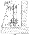
- the wire saw machine is intended to use a saw wire 1, which is usually covered with diamond chips or other suitable abrasive materials, a concrete body, masonry, stone or the like. to saw.
- the sawing rope 1 which is assembled into an endless loop, is looped around the body 2 to be separated and fed to a rope sawing machine 3 via deflection rollers.
- the wire saw 3 contains a frame 4 on which there is an upper stationary roller carrier 5 and a lower movable roller carrier 6.
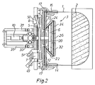
- the saw cable 1 is driven by two hydraulic motors 7, 8 arranged on the inlet and outlet sides.
- a chain drive 9 acting on the lower, movable roller carrier 6 is provided, which is driven by a hydraulic motor 10 which is independent of the cable drive.
- a first cable guide roller 12 on the upper roller carrier 5 is included connected to the hydraulic motor 7, a second one, on the upper one Pulley 5 located rope pulley 13 is on the opposite Drive connected side with the second hydraulic motor 8.
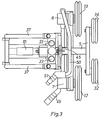
- a further deflection roller 14, 16 is attached to a turntable 17 on the left and right.
- These two lowermost deflection rollers 14, 16, each rotatably attached to an inclined support 25, determine the cutting plane of the saw cable 1.
- the supports 11 are adjustable in height along the frame 4 and can be locked in the selected position.
- the inclined supports 25 for the cable pulleys 14, 16 are on one Turntable 17 mounted with a vertical axis of rotation and can be by means of Lock the locking bolt 21 in the desired positions.
- On the lower roller carrier 6 is also a further cable pulley 20.
- These rope deflection rollers 12, 13 and 20 lie in a first rope running level A.
- two lower cable guide pulleys 22, 24, which are inclined approximately at an angle of 45 °, are present on the lower roller carrier 6, which thus together form a right angle, which opens towards the concrete body 2.
- the lower roller carrier 6 contains a further cable deflection roller 26 which, together with the two cable deflection rollers 32 and 34 seated on the upper roller carrier 5, are all in the second rope running level B.
- the frame 4 on which the upper and lower roller carriers 5, 6 are seated contains two parallel cylindrical rods 33, which can be pivoted on the frame foot about a horizontal bolt 35 are.
- Two parallel oblique struts 37 are at the upper end of the frame Axes 39 supported.
- the lower end of the struts 37 is with the Frame foot connected by floor rails 41.
- the height of the movable roller carrier 6 is adjusted by a chain drive with an endless chain 43. This is above and led down by a sprocket 45 each.
- the upper sprocket 45 is in connection with a drive motor, which is preferably a hydraulic motor 10 with connections 47. With this motor drive the lower roller carrier 6 can thus be moved along the rods 33 in Move in the direction of the double arrow C.
- Pressure oil is supplied to the two hydraulic motors 7, 8 through connection sockets 49, 51 and hose or pipe lines 50.
- the return flow takes place via return lines, not shown instead of.
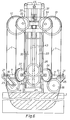
- FIGS. 4 shows a first embodiment of the cable guide, wherein here, in contrast to FIGS. 1 and 2, the parting plane is not horizontal, but vertical.
- the one to be separated Structure 2 looped saw cable 1 runs over the pulleys 14, afterwards over the first deflection roller 12 on the upper roller carrier 5 and then over the deflection roller 20 on the lower roller carrier 6, up over the second deflecting roller 13 of the upper roller carrier 5 and finally over the pulley 16. All rope strands are located in the same rope level A.
- the lower roller carrier 6 with the deflection roller 20 is approximately in its lowermost end position.
- the roller carrier 6 is brought into its upper end position by the chain hoist 43.
- the drive motor 10 of the chain hoist 43 By means of the drive motor 10 of the chain hoist 43, the roller carrier 6 is slowly moved downward, and as a result the saw cable 1 is constantly tensioned in accordance with the sawing progress.
- the saw cable is moved around by hand.
- the roller carrier 6 is previously moved into its upper end position by the chain hoist 9.
- the cable guide is as follows: deflecting rollers 14, 12, first oblique roller 22, deflecting rollers 32, 34, second oblique roller 24, deflecting rollers 13, 16.
- the saw rope 1 thus runs in the rope levels A and B.
- the rope tension required for the sawing process is achieved by the downward movement of the roller carrier 6 on which the inclined rollers 22, 24 are seated.
Abstract
Description
Die Erfindung bezieht sich auf eine Seilsägemaschine nach dem
Oberbegriff des Patentanspruches 1.The invention relates to a wire saw machine according to the
Preamble of
Es sind bereits Seilsägemaschinen bekannt, bei denen das Sägeseil in
Form einer endlosen Schleife um den zu trennenden Betonkörper
od.dgl. geschlungen wird. Mit zunehmender Schnitt-Tiefe muss die
Sägeseilschlaufe zur Aufrechterhaltung des Schnittdruckes das Seil
ständig nachgezogen werden. Zu diesem Zweck befindet sich die
Seilantriebseinrichtung auf einem entlang von horizontalen Schienen
fahrbaren Wagen oder Schlitten. Bei grossen zu trennenden Körpern
bedingt dies lange Seilschlaufen, einen langen Fahrweg und entsprechend
lange Schienen.
In vielen Fällen verhindern indessen gegebene, enge Platzverhältnisse
das Auslegen langer Schienen, was die Verwendung solcher
Seilsägemaschinen begrenzt.Rope sawing machines are already known in which the saw rope or the like in the form of an endless loop around the concrete body to be separated. is looped. As the depth of cut increases, the saw rope loop must be retightened to maintain the cutting pressure. For this purpose, the cable drive device is located on a carriage or carriage that can be moved along horizontal rails. With large bodies to be separated, this requires long rope loops, a long travel path and correspondingly long rails.
In many cases, however, the limited space available prevents long rails from being laid out, which limits the use of such wire saws.
Mit der Erfindung soll die Aufgabe gelöst werden, eine Seilsägemaschine mit möglichst kompaktem und einfachem Aufbau zu schaffen, die auch bei räumlicher Begrenzung einsetzbar ist.The object of the invention is to achieve a wire saw machine with the most compact and simple structure possible, which can also be used with limited space.
Diese Aufgabe wird durch die im Kennzeichen des Anspruches 1 genannten
Merkmale gelöst.This object is achieved by those mentioned in the characterizing part of
Durch die Ausbildung des Seilspeichers in Form eines Flaschenzuges gelingt es, den mit zunehmender Schnitt-Tiefe anfallenden Seilvorrat in sehr platzsparender Weise aufzunehmen (siehe z.B. die JP-A-05-098813).By designing the rope storage in the form of a pulley the rope supply that accumulates with increasing depth of cut succeeds in a very space-saving manner (see e.g. JP-A-05-098813).
Die Ausführungsform nach der Erfindung besteht darin, dass schräg gestellte Seilumlenkrollen vorhanden sind, welche gestatten, das Sägeseil in unterschiedliche Seillaufebenen umzulenken, sodass die Zahl der Seilstränge und damit die Seilaufnahmekapazität variiert werden kann.The embodiment according to the invention is that inclined Rope deflection rollers are available which allow the saw rope redirect to different rope levels so that the number the rope strands and thus the rope holding capacity can be varied can.
Die Verwendung von zwei parallel steuerbaren Hydraulikmotoren für den Sägeseilantrieb ermöglicht ein langsames Anfahren zu Beginn der Sägeseilbewegung Dadurch lassen sich die auf das Sägeseil einwirkenden Zugkräfte gut beherrschen und Seilbrüche durch Überbeanspruchung namentlich bei Laufbeginn vermeiden.The use of two hydraulic motors controllable in parallel for the saw cable drive enables a slow start at the beginning the saw cable movement This allows the on the saw cable Control the tensile forces acting well and rope breaks due to excessive stress Avoid especially at the start of the run.
Zur Anpassung an den fortschreitenden Trennvorgang lässt sich die frei werdende Seilschlaufe von Hand auf unterschiedliche Seilumlenkrollen und damit unterschiedliche Seilstrangzahlen umhängen, was einen besonders kompakten Aufbau der Seilsägemaschine ermöglicht. To adapt to the progressive separation process, the free rope loop by hand on different rope pulleys and thus transfer different numbers of rope strands, which enables a particularly compact construction of the wire saw machine.
In der Zeichnung ist ein Ausführungsbeispiel des Erfindungsgegenstandes dargestellt und wird nachfolgend näher erläutert. Es zeigen:
- Fig.1
- eine Seitenansicht einer Seilsägemaschine samt einem zu trennenden Betonkörper
- Fig.2
- eine Draufsicht auf die Seilsägemaschine mit zu trennendem Baukörper
- Fig.3
- eine Draufsicht auf den oberen Rollenträger, ohne Sägeseil
- Fig.4
- eine Frontansicht der Seilsägemaschine mit einer ersten Art der Seilführung
- Fig.5
- eine Frontansicht der Seilsägemaschine mit einer zweiten Art der Seilführung
- Fig.6
- eine Frontansicht der Seilsägemaschine mit einer dritten Art der Seilführung
- Fig. 1
- a side view of a wire saw machine including a concrete body to be separated
- Fig. 2
- a plan view of the wire saw with the building to be separated
- Fig. 3
- a top view of the upper roller carrier, without saw cable
- Fig. 4
- a front view of the wire saw machine with a first type of rope guide
- Fig. 5
- a front view of the wire saw machine with a second type of rope guide
- Fig. 6
- a front view of the wire saw machine with a third type of rope guide
Die Seilsägemaschine ist dazu bestimmt, mittels eines Sägeseiles 1,
das üblicherweise mit Diamantsplittern oder andern geeigneten Abrasivstoffen
besetzt ist, einen Betonkörper, Mauerwerk, Gestein
od.dgl. zu zersägen. Zu diesem Zweck wird das zu einer endlosen
Schleife zusammengesetzte Sägeseil 1 um den zu trennenden Körper
2 geschlungen und über Umlenkrollen einer Seilsägemaschine 3 zugeführt.
Die Seilsägemaschine 3 enthält ein Gestell 4 auf dem sich
ein oberer stationärer Rollenträger 5 und ein unterer beweglich gelagerter
Rollenträger 6 befindet. Der Antrieb des Sägeseiles 1 erfolgt
durch zwei einlauf- und auslaufseitig angeordnete Hydraulikmotoren
7,8.
Für das Spannen des Sägeseiles 1 zur Erzeugung des Schnittdruckes
ist ein auf den unteren, beweglichen Rollenträger 6 einwirkender
Kettenantrieb 9 vorhanden, der von einem vom Seilantrieb unabhängigen
Hydraulikmotor 10 angetrieben ist. The wire saw machine is intended to use a
For tensioning the
Eine erste Seilumlenkrolle 12 auf dem oberen Rollenträger 5 ist mit
dem Hydraulikmotor 7 antriebsverbunden, eine zweite, auf dem oberen
Rollenträger 5 befindliche Seilumlenkrolle 13 ist auf der gegenüberliegenden
Seite mit dem zweiten Hydraulikmotor 8 antriebsverbunden.A first
Auf einem am Fuss des Gestelles 4 lösbar befestigten Träger 11 ist
links und rechts je eine weitere Umlenkrolle 14,16 je auf einem
Drehteller 17 befestigt. Diese beiden untersten je an einer Schrägstütze
25 drehbar befestigten Umlenkrollen 14,16 bestimmen die
Schnittebene des Sägeseiles 1.
Zur Einstellung deren Seillage sind die Träger 11 entlang des Gestelles
4 höhenverstellbar und in der gewählten Stellung arretierbar ausgebildet.On a
In order to adjust the rope position, the
Die Schrägstützen 25 für die Seilumlenkrollen 14,16 sind auf einem
Drehteller 17 mit vertikaler Drehachse gelagert und lassen sich mittels
Arretierbolzen 21 in gewünschten Positionen arretieren. Auf
dem unteren Rollenträger 6 sitzt ferner eine weitere Seilumlenkrolle
20. Diese Seilumlenkrollen 12,13 und 20 liegen in einer ersten Seillaufebene
A.The
Zur Umlenkung des Sägeseiles 1 in eine zweite Seillaufebene B sind
am unteren Rollenträger 6 zwei etwa im Winkel von 45° schräg gestellte
Seilumlenkrollen 22,24 vorhanden, die somit zusammen einen
rechten Winkel einschliessen, der sich gegen den Betonkörper 2 hin
öffnet.
Der untere Rollenträger 6 enthält eine weitere Seilumlenkrolle 26,
die sich zusammen mit den beiden auf dem oberen Rollenträger 5
sitzenden Seilumlenkrollen 32 und 34 alle in der zweiten Seillaufebene
B befinden.For deflecting the
The
Das Gestell 4 auf welchem der obere und untere Rollenträger 5,6 sitzen,
enthält zwei untereinander parallele zylindrische Stangen 33,
die am Gestellfuss um einen horizontalen Bolzen 35 schwenkbar
sind. The frame 4 on which the upper and
Zwei parallel schräge Streben 37 sind am oberen Gestellende durch
Achsen 39 abgestützt. Das untere Ende der Streben 37 ist mit dem
Gestellfuss durch Bodenschienen 41 verbunden. Durch Veränderung
der Länge der Bodenschienen 41 oder des Abstützpunktes der Strebe
37 können die Stangen 33 bei Bedarf geneigt werden.Two parallel
Die Höhenverstellung des beweglichen Rollenträgers 6 erfolgt durch
einen Kettenantrieb mit einer endlosen Kette 43. Diese ist oben und
unten je um ein Kettenrad 45 geführt. Das obere Kettenrad 45 steht
mit einem Antriebsmotor in Verbindung, der vorzugsweise ein Hydraulikmotor
10 mit Anschlüssen 47 ist. Mit diesem Motorantrieb
lässt sich somit der untere Rollenträger 6 entlang den Stangen 33 in
Richtung des Doppelpfeiles C bewegen.The height of the
Die Zufuhr von Drucköl zu den beiden Hydraulikmotoren 7,8 erfolgt
durch Anschlussnippen 49,51 und Schlauch- oder Rohrleitungen 50.
Der Rückfluss findet über nicht näher dargestellte Rücklaufleitungen
statt.Pressure oil is supplied to the two
Mit fortschreitendem Sägevorgang wird die frei werdenden Seillänge von Hand um unterschiedliche Umlenkrollen umgehängt, wie das nachfolgend an Hand der Fig. 4 - 6 näher beschrieben wird. Dadurch ergeben sich Flaschenzüge mit Mehrfach-Untersetzung und mit einer unterschiedlichen Zahl von Seilzügen.As the sawing process progresses, the rope length that becomes free becomes available by hand around different pulleys, like that is described in more detail below with reference to FIGS. 4-6. Thereby there are pulleys with multiple reduction and with one different number of cables.
Aus Fig.4 geht eine erste Ausbildung der Seilführung hervor, wobei
hier im Gegensatz zu den Fig.1 und 2 die Trennebene nicht
waagrecht, sondern senkrecht verläuft. Das um den zu trennenden
Baukörper 2 geschlungene Sägeseil 1 läuft über die Umlenkrollen
14, hernach über die erste Umlenkrolle 12 am oberen Rollenträger 5
und sodann über die Umlenkrolle 20 am unteren Rollenträger 6,
herauf über die zweite Umlenkrolle 13 des oberen Rollenträgers 5
und schliesslich über die Umlenkrolle 16. Alle Seilstränge befinden
sich in der gleichen Seilebene A. 4 shows a first embodiment of the cable guide, wherein
here, in contrast to FIGS. 1 and 2, the parting plane is not
horizontal, but vertical. The one to be separated
Bei der in Fig.4 dargestellten Ausführungsform befindet sich der
untere Rollenträger 6 mit der Umlenkrolle 20 angenähert in seiner
untersten Endlage. Zu Beginn des Sägevorganges wird der Rollenträger
6 durch den Kettenzug 43 in seine obere Endlage gebracht.
Durch den Antriebsmotor 10 des Kettenzuges 43 wird der Rollenträger
6 langsam abwärts bewegt und dadurch das Sägeseil 1 entsprechend
dem Sägefortschritt ständig gespannt wird. Wenn die in Fig.4
dargestellte untere Endlage des Rollenträgers 6 erreicht ist, wird das
Sägeseil von Hand umgehängt. Vorgängig wird der Rollenträger 6
durch den Kettenzug 9 in seine obere Endlage bewegt.
Gemäss Fig. 5 ist die Seilführung wie folgt: Umlenkrollen 14,12,
erste Schrägrolle 22, Umlenkrollen 32,34, zweite Schrägrolle 24,
Umlenkrollen 13,16.
Das Sägeseil 1 läuft somit in den Seilebenen A und B. Die für den
Sägevorgang erforderliche Seilspannung wird durch Abwärtsbewegung
des Rollenträgers 6 erreicht, auf dem die Schrägrollen 22,24
sitzen.In the embodiment shown in FIG. 4, the
5, the cable guide is as follows: deflecting
The
Zu Fig.6 ist die Seilführung nach einem weiteren Umhängevorgang
dargestellt, wobei zuvor der Rollenträger 6 in seine obere Ausgangsstellung
gebracht wird. Die Seilführung ist nun wie folgt: Rollen
14,12,22,32,26,34,24,13,16. Durch Bewegung des Rollenträgers
6 in Abwärtsrichtung wird das Sägeseil 1 gespannt.6 shows the cable guide after another transfer process
shown, previously the
Als Ausführungsvariante könnte an Stelle eines Kettenzuges auch eine
parallel zu den Stangen 33 verlaufende Zahnstange und ein in
diese eingreifendes, auf dem Rollenträger 6 sitzendes angetriebenes
Ritzel vorhanden sein.
An Stelle der bevorzugten vertikalen Lage des Gestelles 4 könnte
dieses auch schräg gestellt oder liegend ausgeführt werden.As a variant, instead of a chain hoist, there could also be a toothed rack running parallel to the
Instead of the preferred vertical position of the frame 4, this could also be carried out obliquely or horizontally.
Claims (7)
- Rope-type sawing machine for making severing cuts in rock, bodies of concrete, masonry or the like, with a motor-driven saw rope equipped with abrasive material, for the loop part of the saw rope (1) projecting from the body (2) to be severed, there are pulley-block rope store means with a frame (4) and stationary and movably mounted pulleys (5,6), around which the saw rope (1) is looped, the movable pulley carrier (6) being movable linearly by means of a power drive (10,45), characterised in that at least on one pulley carrier (5,6) inclined pulleys (22,24) are provided for deflecting the sawing rope (1) into different rope running planes (A,B).
- Rope sawing machine according to claim 1, characterised in that the top pulley carrier (5) as a fixed pulley carrier is provided with a first set of pulleys with two from each other radially distanced pulleys (12, 13) for the rope guidance in a first rope plane, oil the top pulley carrier (5) is provided a second set of pulleys with two from each other radially distanced pulleys (32, 34), those pulleys (32, 34) having an axial distance to the first set of pulleys for the rope guidance in a second rope plane, the bottom movably beared pulley carrier (6) is provided with a third set of pulleys (14, 16) pivotally beared and at least one additional pulley (26), and a pivotable arranged fourth set of pulleys (22, 24) is used fastened on a carrier (11) which is adjustable along and detachable fixed on the frame (4).
- Rope sawing machine according to the claims 1 or 2, characterised in that the rope drive takes place by two parallel controllable hydraulic motors (7,8) arranged on the rope inlet and rope outlet side.
- Rope sawing machine according to any one of the claims 1 to 3, characterised in that the movable pulley carrier (6) can be moved along two parallel guide rods (33) supported by the frame (4) and the frame can be swiveled around a horizontal axis or rotation (35) provided on the base of the frame.
- Rope sawing machine according to any one of the claims 1 to 4, characterised in that the frame has two rods (33) or guide rails arranged parallel to each other for the guidance of the movable pulley carrier (6).
- Rope sawing machine according to any one of the claims 1 to 5, characterised in that the drive takes place by a motor-driven chain drive (9,43,45) for the movement of the pulley carrier (6).
- Method particularly for operating the rope sawing machine according to claim 1, characterised in that as the depth of the cut increases, to increase the number of rope lines and accordingly the rope storage capacity of the pulley block means, the free sawing rope is hung by hand around various rope deflecting pulleys (12,13,22,24,26) into different rope running planes (A, B).
Applications Claiming Priority (3)
| Application Number | Priority Date | Filing Date | Title |
|---|---|---|---|
| CH110794 | 1994-04-13 | ||
| CH1107/94 | 1994-04-13 | ||
| PCT/CH1994/000186 WO1995028263A1 (en) | 1994-04-13 | 1994-09-21 | Cable saw machine for cutting concrete bodies, walls, rocks or the like |
Publications (2)
| Publication Number | Publication Date |
|---|---|
| EP0703852A1 EP0703852A1 (en) | 1996-04-03 |
| EP0703852B1 true EP0703852B1 (en) | 1998-08-19 |
Family
ID=4202663
Family Applications (1)
| Application Number | Title | Priority Date | Filing Date |
|---|---|---|---|
| EP94926760A Expired - Lifetime EP0703852B1 (en) | 1994-04-13 | 1994-09-21 | Cable saw machine for cutting concrete bodies, walls, rocks or the like |
Country Status (10)
| Country | Link |
|---|---|
| US (1) | US5645040A (en) |
| EP (1) | EP0703852B1 (en) |
| JP (1) | JP2879476B2 (en) |
| AT (1) | ATE169858T1 (en) |
| CA (1) | CA2163366C (en) |
| DE (1) | DE59406744D1 (en) |
| DK (1) | DK0703852T3 (en) |
| ES (1) | ES2120631T3 (en) |
| WO (1) | WO1995028263A1 (en) |
| ZA (1) | ZA952229B (en) |
Cited By (3)
| Publication number | Priority date | Publication date | Assignee | Title |
|---|---|---|---|---|
| DE102004012606B4 (en) * | 2004-03-12 | 2007-06-14 | Cedima Diamantwerkzeug- Und Maschinenhandelsgesellschaft Mbh | Protective device for wire saw devices |
| DE102004012023B4 (en) * | 2004-03-10 | 2007-06-14 | Cedima Diamantenwerkzeug- Und Maschinenhandelsgesellschaft Mbh | Cable saw |
| DE102007008124A1 (en) | 2007-02-19 | 2008-08-21 | Cedima Diamantwerkzeug- Und Maschinenbaugesellschaft Mbh | Wire saw system for cutting e.g. natural stone, has roll package formed in position-adjustable manner relative to another roll package, and protective-cover profile partially covering freely-running wire saw outside wire saw machine |
Families Citing this family (20)
| Publication number | Priority date | Publication date | Assignee | Title |
|---|---|---|---|---|
| EP0766613B1 (en) * | 1995-04-18 | 2002-09-04 | Josef Plattner | Saw cable guiding device |
| AT2194U1 (en) * | 1997-04-09 | 1998-06-25 | Braun Maschf Gmbh | ROPE STORAGE |
| US6279564B1 (en) * | 1997-07-07 | 2001-08-28 | John B. Hodsden | Rocking apparatus and method for slicing a workpiece utilizing a diamond impregnated wire |
| US6170478B1 (en) * | 1998-10-15 | 2001-01-09 | Richard S. Gorder | Process and apparatus for cutting a chamfer in concrete |
| ES2305044T3 (en) * | 2000-01-24 | 2008-11-01 | Graniterie Petitjean Sas | CHECK TO INSERT A CUTTING SLOT. |
| JP2002086441A (en) * | 2000-09-18 | 2002-03-26 | Shibuya:Kk | Wire saw cutting device and wire saw cutting device unit |
| US7055650B2 (en) * | 2001-05-17 | 2006-06-06 | Jlg Industries, Inc. | Saw accessory for aerial work platform |
| DE10148492A1 (en) * | 2001-10-01 | 2003-04-17 | Hilti Ag | wire saw |
| US8056633B2 (en) * | 2008-04-28 | 2011-11-15 | Barra Marc T | Apparatus and method for removing subsea structures |
| WO2010128903A1 (en) * | 2009-05-04 | 2010-11-11 | Husqvarna Ab | A wire saw and a method of rebuilding a wall saw to a wire saw |
| CN101791827B (en) * | 2010-01-22 | 2015-02-04 | 侯平常 | Diamond wire saw stone hole mining device |
| US8651098B2 (en) * | 2010-03-04 | 2014-02-18 | MacTech, Inc. | Apparatus, system and method for using a diamond-impregnated wire to cut an object |
| IT1401683B1 (en) * | 2010-08-27 | 2013-08-02 | Gambini Int Sa | CUTTING DEVICE FOR ROLLS OF RIBBED MATERIAL, IN PARTICULAR PAPER. |
| JP2016043532A (en) * | 2014-08-21 | 2016-04-04 | 日本地工株式会社 | Electric pole cutting device and electric pole cutting method |
| NO342783B1 (en) * | 2016-08-12 | 2018-08-06 | 1Diamond As | Magazine wire saw |
| NO345448B1 (en) | 2018-01-30 | 2021-02-01 | 1Diamond As | Inclined cut GBS leg |
| JP7012042B2 (en) * | 2019-03-30 | 2022-01-27 | テクノス株式会社 | Deck cutting method and cutting device |
| JP7255803B2 (en) * | 2019-07-26 | 2023-04-11 | 株式会社大林組 | Cutting device and method for cutting and separating concrete floor slab and main girder |
| USD909164S1 (en) * | 2020-07-15 | 2021-02-02 | Yongkang Yizu Trading Co., Ltd | Rope saw |
| CN114038605B (en) * | 2021-11-08 | 2023-08-15 | 中国核动力研究设计院 | Remote dismounting device and method for bead string rope of diamond wire saw |
Family Cites Families (10)
| Publication number | Priority date | Publication date | Assignee | Title |
|---|---|---|---|---|
| FR312582A (en) * | 1900-01-01 | |||
| FR612372A (en) * | 1926-03-06 | 1926-10-22 | Accumulator with sheaves, for wires or cables, for equipping limestone sawing devices, and the like, called helical wire, fixed or mobile, with a long wire or cable, although there is only one space available restricted | |
| US4494523A (en) * | 1983-08-05 | 1985-01-22 | Motorola, Inc. | Wire saw |
| IT1199484B (en) * | 1984-03-14 | 1988-12-30 | Paolo Bresciani | CAROUSEL LATHE FOR CONCENTRIC, CYLINDRICAL, CONICAL, HYPERBOLIC AND CUP CUTTING, OF MARBLE, STONE AND GRANITE BLOCKS, WITH DIAMOND OR HELICAL WIRE TOOL |
| JPS63189207A (en) * | 1987-01-31 | 1988-08-04 | 株式会社 ダイモ社 | Method of wire sewing construction of reinforced concrete structure |
| CH669554A5 (en) * | 1987-02-18 | 1989-03-31 | Forbeton Betonbohr S A | |
| JPS6422406U (en) * | 1987-07-31 | 1989-02-06 | ||
| JPH03126554U (en) * | 1990-04-04 | 1991-12-19 | ||
| JPH0598813A (en) * | 1991-10-03 | 1993-04-20 | Concrete Kooring Kk | Tension imparting process in wire saw method |
| DE4239212C2 (en) * | 1992-11-21 | 1994-11-24 | Peter Loeffelbein | Rope saw tensioning device |
-
1994
- 1994-09-21 WO PCT/CH1994/000186 patent/WO1995028263A1/en active IP Right Grant
- 1994-09-21 DK DK94926760T patent/DK0703852T3/en active
- 1994-09-21 JP JP7526596A patent/JP2879476B2/en not_active Expired - Lifetime
- 1994-09-21 DE DE59406744T patent/DE59406744D1/en not_active Expired - Lifetime
- 1994-09-21 US US08/564,199 patent/US5645040A/en not_active Expired - Lifetime
- 1994-09-21 EP EP94926760A patent/EP0703852B1/en not_active Expired - Lifetime
- 1994-09-21 ES ES94926760T patent/ES2120631T3/en not_active Expired - Lifetime
- 1994-09-21 AT AT94926760T patent/ATE169858T1/en active
- 1994-09-21 CA CA002163366A patent/CA2163366C/en not_active Expired - Lifetime
-
1995
- 1995-03-17 ZA ZA952229A patent/ZA952229B/en unknown
Cited By (3)
| Publication number | Priority date | Publication date | Assignee | Title |
|---|---|---|---|---|
| DE102004012023B4 (en) * | 2004-03-10 | 2007-06-14 | Cedima Diamantenwerkzeug- Und Maschinenhandelsgesellschaft Mbh | Cable saw |
| DE102004012606B4 (en) * | 2004-03-12 | 2007-06-14 | Cedima Diamantwerkzeug- Und Maschinenhandelsgesellschaft Mbh | Protective device for wire saw devices |
| DE102007008124A1 (en) | 2007-02-19 | 2008-08-21 | Cedima Diamantwerkzeug- Und Maschinenbaugesellschaft Mbh | Wire saw system for cutting e.g. natural stone, has roll package formed in position-adjustable manner relative to another roll package, and protective-cover profile partially covering freely-running wire saw outside wire saw machine |
Also Published As
| Publication number | Publication date |
|---|---|
| JPH08511746A (en) | 1996-12-10 |
| ES2120631T3 (en) | 1998-11-01 |
| CA2163366A1 (en) | 1995-10-26 |
| CA2163366C (en) | 2005-08-09 |
| US5645040A (en) | 1997-07-08 |
| WO1995028263A1 (en) | 1995-10-26 |
| EP0703852A1 (en) | 1996-04-03 |
| ZA952229B (en) | 1995-12-14 |
| JP2879476B2 (en) | 1999-04-05 |
| DK0703852T3 (en) | 1999-05-25 |
| DE59406744D1 (en) | 1998-09-24 |
| ATE169858T1 (en) | 1998-09-15 |
Similar Documents
| Publication | Publication Date | Title |
|---|---|---|
| EP0703852B1 (en) | Cable saw machine for cutting concrete bodies, walls, rocks or the like | |
| EP1700809B1 (en) | Elevator system | |
| EP2216117B1 (en) | Rope saw and method for operating same | |
| AT402710B (en) | ROPE SAW MACHINE | |
| DE10225183A1 (en) | Demolition machine for especially walls has transporting device mounted on top of wall and movable along it, and means to support transporting device on wall and which are brought into engagement with sides of wall | |
| DE19754520A1 (en) | Wire saw | |
| DE3718281C2 (en) | ||
| DE102014103271B4 (en) | Wire saw apparatus and use of a wire saw device | |
| DE202005006442U1 (en) | Rope saw machine for cutting workpiece e.g. concrete, has saw rope guided in guide rollers in area of its cutting line in workpiece, where rollers are vertically adjustable in guides corresponding to progress of line, by motor | |
| CH693087A5 (en) | Wire saw | |
| DE98977C (en) | ||
| CH688816A5 (en) | Rope saw machine for producing dividing cuts in stone, concrete bodies or walls | |
| DE1653126C3 (en) | Device for delimbing and debarking felled trees | |
| DE1502967C3 (en) | Revolving circular saw device | |
| DE3124852A1 (en) | MATERIAL UNLOADING DEVICE | |
| DE95797C (en) | ||
| DE1627276A1 (en) | Cut-to-length shears for metal sheets | |
| DE2639369A1 (en) | Multiple stone block sawing machine - has cutting frames driven by flywheel and crankshaft between two pairs of stone blocks | |
| DE389358C (en) | Mining machine | |
| DE3141708C2 (en) | Jig | |
| DE57187C (en) | Water pressure - Lauf krahn with special rope arrangement | |
| DE1929709C (en) | Drive for the slide of a cone setting machine | |
| DE1080946B (en) | Process for the extraction and promotion of coal in low struts of small length and device for carrying out this process | |
| DE2348442A1 (en) | DEVICE FOR CAGE SAWS FOR ALIGNMENT OF THE LOGS TO BE DISCONNECTED IN RELATION TO THEIR ANGLE POSITION AND FOR THEIR INTRODUCTION INTO THE MACHINE | |
| DE43743C (en) | Innovation on cutting devices for brick presses |
Legal Events
| Date | Code | Title | Description |
|---|---|---|---|
| PUAI | Public reference made under article 153(3) epc to a published international application that has entered the european phase |
Free format text: ORIGINAL CODE: 0009012 |
|
| AK | Designated contracting states |
Kind code of ref document: A1 Designated state(s): AT BE CH DE DK ES FR GB GR IE IT LI LU NL PT SE |
|
| 17P | Request for examination filed |
Effective date: 19960227 |
|
| GRAG | Despatch of communication of intention to grant |
Free format text: ORIGINAL CODE: EPIDOS AGRA |
|
| GRAG | Despatch of communication of intention to grant |
Free format text: ORIGINAL CODE: EPIDOS AGRA |
|
| GRAH | Despatch of communication of intention to grant a patent |
Free format text: ORIGINAL CODE: EPIDOS IGRA |
|
| 17Q | First examination report despatched |
Effective date: 19980209 |
|
| GRAH | Despatch of communication of intention to grant a patent |
Free format text: ORIGINAL CODE: EPIDOS IGRA |
|
| GRAA | (expected) grant |
Free format text: ORIGINAL CODE: 0009210 |
|
| AK | Designated contracting states |
Kind code of ref document: B1 Designated state(s): AT BE CH DE DK ES FR GB GR IE IT LI LU NL PT SE |
|
| REF | Corresponds to: |
Ref document number: 169858 Country of ref document: AT Date of ref document: 19980915 Kind code of ref document: T |
|
| REG | Reference to a national code |
Ref country code: CH Ref legal event code: EP |
|
| REG | Reference to a national code |
Ref country code: CH Ref legal event code: NV Representative=s name: LUCHS & PARTNER PATENTANWAELTE |
|
| REF | Corresponds to: |
Ref document number: 59406744 Country of ref document: DE Date of ref document: 19980924 |
|
| GBT | Gb: translation of ep patent filed (gb section 77(6)(a)/1977) |
Effective date: 19981002 |
|
| REG | Reference to a national code |
Ref country code: ES Ref legal event code: FG2A Ref document number: 2120631 Country of ref document: ES Kind code of ref document: T3 |
|
| ET | Fr: translation filed | ||
| REG | Reference to a national code |
Ref country code: IE Ref legal event code: FG4D Free format text: GERMAN |
|
| REG | Reference to a national code |
Ref country code: PT Ref legal event code: SC4A Free format text: AVAILABILITY OF NATIONAL TRANSLATION Effective date: 19981021 |
|
| PLBQ | Unpublished change to opponent data |
Free format text: ORIGINAL CODE: EPIDOS OPPO |
|
| REG | Reference to a national code |
Ref country code: DK Ref legal event code: T3 |
|
| PLBI | Opposition filed |
Free format text: ORIGINAL CODE: 0009260 |
|
| PLBF | Reply of patent proprietor to notice(s) of opposition |
Free format text: ORIGINAL CODE: EPIDOS OBSO |
|
| 26 | Opposition filed |
Opponent name: EURODIMA DIAMANT-TECHNIK GMBH Effective date: 19990519 |
|
| PGFP | Annual fee paid to national office [announced via postgrant information from national office to epo] |
Ref country code: PT Payment date: 19990917 Year of fee payment: 6 |
|
| PGFP | Annual fee paid to national office [announced via postgrant information from national office to epo] |
Ref country code: DK Payment date: 19990920 Year of fee payment: 6 |
|
| PGFP | Annual fee paid to national office [announced via postgrant information from national office to epo] |
Ref country code: NL Payment date: 19990921 Year of fee payment: 6 |
|
| PGFP | Annual fee paid to national office [announced via postgrant information from national office to epo] |
Ref country code: SE Payment date: 19990922 Year of fee payment: 6 Ref country code: LU Payment date: 19990922 Year of fee payment: 6 |
|
| PGFP | Annual fee paid to national office [announced via postgrant information from national office to epo] |
Ref country code: ES Payment date: 19990923 Year of fee payment: 6 |
|
| PGFP | Annual fee paid to national office [announced via postgrant information from national office to epo] |
Ref country code: GR Payment date: 19990927 Year of fee payment: 6 |
|
| PGFP | Annual fee paid to national office [announced via postgrant information from national office to epo] |
Ref country code: IE Payment date: 19990928 Year of fee payment: 6 |
|
| PGFP | Annual fee paid to national office [announced via postgrant information from national office to epo] |
Ref country code: BE Payment date: 19990929 Year of fee payment: 6 |
|
| PLBF | Reply of patent proprietor to notice(s) of opposition |
Free format text: ORIGINAL CODE: EPIDOS OBSO |
|
| PG25 | Lapsed in a contracting state [announced via postgrant information from national office to epo] |
Ref country code: LU Free format text: LAPSE BECAUSE OF NON-PAYMENT OF DUE FEES Effective date: 20000921 Ref country code: IE Free format text: LAPSE BECAUSE OF NON-PAYMENT OF DUE FEES Effective date: 20000921 Ref country code: DK Free format text: LAPSE BECAUSE OF NON-PAYMENT OF DUE FEES Effective date: 20000921 |
|
| PG25 | Lapsed in a contracting state [announced via postgrant information from national office to epo] |
Ref country code: ES Free format text: LAPSE BECAUSE OF NON-PAYMENT OF DUE FEES Effective date: 20000922 |
|
| PG25 | Lapsed in a contracting state [announced via postgrant information from national office to epo] |
Ref country code: SE Free format text: THE PATENT HAS BEEN ANNULLED BY A DECISION OF A NATIONAL AUTHORITY Effective date: 20000929 |
|
| PG25 | Lapsed in a contracting state [announced via postgrant information from national office to epo] |
Ref country code: GR Free format text: LAPSE BECAUSE OF NON-PAYMENT OF DUE FEES Effective date: 20000930 Ref country code: BE Free format text: LAPSE BECAUSE OF NON-PAYMENT OF DUE FEES Effective date: 20000930 |
|
| PLAW | Interlocutory decision in opposition |
Free format text: ORIGINAL CODE: EPIDOS IDOP |
|
| BERE | Be: lapsed |
Owner name: HYDROSTRESS A.G. Effective date: 20000930 |
|
| PG25 | Lapsed in a contracting state [announced via postgrant information from national office to epo] |
Ref country code: PT Free format text: LAPSE BECAUSE OF NON-PAYMENT OF DUE FEES Effective date: 20010331 |
|
| PG25 | Lapsed in a contracting state [announced via postgrant information from national office to epo] |
Ref country code: NL Free format text: LAPSE BECAUSE OF NON-PAYMENT OF DUE FEES Effective date: 20010401 |
|
| APAC | Appeal dossier modified |
Free format text: ORIGINAL CODE: EPIDOS NOAPO |
|
| APAE | Appeal reference modified |
Free format text: ORIGINAL CODE: EPIDOS REFNO |
|
| EUG | Se: european patent has lapsed |
Ref document number: 94926760.3 |
|
| REG | Reference to a national code |
Ref country code: DK Ref legal event code: EBP |
|
| NLV4 | Nl: lapsed or anulled due to non-payment of the annual fee |
Effective date: 20010401 |
|
| REG | Reference to a national code |
Ref country code: IE Ref legal event code: MM4A |
|
| REG | Reference to a national code |
Ref country code: PT Ref legal event code: MM4A Free format text: LAPSE DUE TO NON-PAYMENT OF FEES Effective date: 20010331 |
|
| APAE | Appeal reference modified |
Free format text: ORIGINAL CODE: EPIDOS REFNO |
|
| REG | Reference to a national code |
Ref country code: GB Ref legal event code: IF02 |
|
| PGFP | Annual fee paid to national office [announced via postgrant information from national office to epo] |
Ref country code: GB Payment date: 20020829 Year of fee payment: 9 |
|
| APAC | Appeal dossier modified |
Free format text: ORIGINAL CODE: EPIDOS NOAPO |
|
| APAC | Appeal dossier modified |
Free format text: ORIGINAL CODE: EPIDOS NOAPO |
|
| PLBO | Opposition rejected |
Free format text: ORIGINAL CODE: EPIDOS REJO |
|
| PLBN | Opposition rejected |
Free format text: ORIGINAL CODE: 0009273 |
|
| STAA | Information on the status of an ep patent application or granted ep patent |
Free format text: STATUS: OPPOSITION REJECTED |
|
| 27O | Opposition rejected |
Effective date: 20030311 |
|
| PG25 | Lapsed in a contracting state [announced via postgrant information from national office to epo] |
Ref country code: GB Free format text: LAPSE BECAUSE OF NON-PAYMENT OF DUE FEES Effective date: 20030921 |
|
| REG | Reference to a national code |
Ref country code: ES Ref legal event code: FD2A Effective date: 20011011 |
|
| GBPC | Gb: european patent ceased through non-payment of renewal fee |
Effective date: 20030921 |
|
| PG25 | Lapsed in a contracting state [announced via postgrant information from national office to epo] |
Ref country code: IT Free format text: LAPSE BECAUSE OF NON-PAYMENT OF DUE FEES;WARNING: LAPSES OF ITALIAN PATENTS WITH EFFECTIVE DATE BEFORE 2007 MAY HAVE OCCURRED AT ANY TIME BEFORE 2007. THE CORRECT EFFECTIVE DATE MAY BE DIFFERENT FROM THE ONE RECORDED. Effective date: 20050921 |
|
| APAH | Appeal reference modified |
Free format text: ORIGINAL CODE: EPIDOSCREFNO |
|
| PGFP | Annual fee paid to national office [announced via postgrant information from national office to epo] |
Ref country code: AT Payment date: 20130913 Year of fee payment: 20 Ref country code: CH Payment date: 20130926 Year of fee payment: 20 Ref country code: DE Payment date: 20130927 Year of fee payment: 20 |
|
| PGFP | Annual fee paid to national office [announced via postgrant information from national office to epo] |
Ref country code: FR Payment date: 20130918 Year of fee payment: 20 |
|
| REG | Reference to a national code |
Ref country code: DE Ref legal event code: R071 Ref document number: 59406744 Country of ref document: DE |
|
| REG | Reference to a national code |
Ref country code: DE Ref legal event code: R071 Ref document number: 59406744 Country of ref document: DE |
|
| REG | Reference to a national code |
Ref country code: CH Ref legal event code: PL |
|
| PG25 | Lapsed in a contracting state [announced via postgrant information from national office to epo] |
Ref country code: DE Free format text: LAPSE BECAUSE OF EXPIRATION OF PROTECTION Effective date: 20140923 |
|
| REG | Reference to a national code |
Ref country code: AT Ref legal event code: MK07 Ref document number: 169858 Country of ref document: AT Kind code of ref document: T Effective date: 20140921 |