EP0703699B1 - Vorrichtung zum Nachweis von Röntgenstrahlung und Bildlesegerät - Google Patents
Vorrichtung zum Nachweis von Röntgenstrahlung und Bildlesegerät Download PDFInfo
- Publication number
- EP0703699B1 EP0703699B1 EP95114815A EP95114815A EP0703699B1 EP 0703699 B1 EP0703699 B1 EP 0703699B1 EP 95114815 A EP95114815 A EP 95114815A EP 95114815 A EP95114815 A EP 95114815A EP 0703699 B1 EP0703699 B1 EP 0703699B1
- Authority
- EP
- European Patent Office
- Prior art keywords
- image
- data
- histogram
- ccd
- memory
- Prior art date
- Legal status (The legal status is an assumption and is not a legal conclusion. Google has not performed a legal analysis and makes no representation as to the accuracy of the status listed.)
- Expired - Lifetime
Links
Images


Classifications
-
- H—ELECTRICITY
- H04—ELECTRIC COMMUNICATION TECHNIQUE
- H04N—PICTORIAL COMMUNICATION, e.g. TELEVISION
- H04N1/00—Scanning, transmission or reproduction of documents or the like, e.g. facsimile transmission; Details thereof
- H04N1/32—Circuits or arrangements for control or supervision between transmitter and receiver or between image input and image output device, e.g. between a still-image camera and its memory or between a still-image camera and a printer device
- H04N1/32101—Display, printing, storage or transmission of additional information, e.g. ID code, date and time or title
-
- H—ELECTRICITY
- H04—ELECTRIC COMMUNICATION TECHNIQUE
- H04N—PICTORIAL COMMUNICATION, e.g. TELEVISION
- H04N1/00—Scanning, transmission or reproduction of documents or the like, e.g. facsimile transmission; Details thereof
- H04N1/32—Circuits or arrangements for control or supervision between transmitter and receiver or between image input and image output device, e.g. between a still-image camera and its memory or between a still-image camera and a printer device
-
- H—ELECTRICITY
- H04—ELECTRIC COMMUNICATION TECHNIQUE
- H04N—PICTORIAL COMMUNICATION, e.g. TELEVISION
- H04N2201/00—Indexing scheme relating to scanning, transmission or reproduction of documents or the like, and to details thereof
- H04N2201/32—Circuits or arrangements for control or supervision between transmitter and receiver or between image input and image output device, e.g. between a still-image camera and its memory or between a still-image camera and a printer device
- H04N2201/3201—Display, printing, storage or transmission of additional information, e.g. ID code, date and time or title
- H04N2201/3225—Display, printing, storage or transmission of additional information, e.g. ID code, date and time or title of data relating to an image, a page or a document
- H04N2201/3242—Display, printing, storage or transmission of additional information, e.g. ID code, date and time or title of data relating to an image, a page or a document of processing required or performed, e.g. for reproduction or before recording
-
- H—ELECTRICITY
- H04—ELECTRIC COMMUNICATION TECHNIQUE
- H04N—PICTORIAL COMMUNICATION, e.g. TELEVISION
- H04N2201/00—Indexing scheme relating to scanning, transmission or reproduction of documents or the like, and to details thereof
- H04N2201/32—Circuits or arrangements for control or supervision between transmitter and receiver or between image input and image output device, e.g. between a still-image camera and its memory or between a still-image camera and a printer device
- H04N2201/3201—Display, printing, storage or transmission of additional information, e.g. ID code, date and time or title
- H04N2201/3278—Transmission
Definitions
- the present invention relates to an X-ray image detecting apparatus for detecting an X-ray image, particularly a medical X-ray image, to convert it into a digital image, and an image reading apparatus for reading a general image to digitalize it.
- EP-A-0 335 419 a method of and apparatus for establishing highlight and shadow densities used for gradation control of image data obtained through reading an original are known. Furthermore, from Gonzalez, Rafael C.: “Digital Image Processing", 30.6.92, Addison-Wesley Publishing Company, USA, pages 173-180, a histogram equalization is known. Moreover, from EP-A-0 560 165 an image scanner system and method for improving the image quality of microfilm by calculating a histogram of pixel values of a scanned microfilm image, generating image statistics from the histogram, using the image statistics to select a look-up table and employing the look-up table to perform a pixel-by-pixel transformation of the microfilm image is known.
- a known example of a device for digitalizing the X-ray image is an X-ray image detecting apparatus which is so arranged that X-rays transmitted by a subject are guided onto a fluorescent screen, a storage-type solid state image sensing device such as CCD receives fluorescence emitted in proportion to X-ray intensity from the fluorescent screen to convert it into video signals, and thereafter the video signals are converted into digital values.
- a device for directly converting X-ray amounts into charge amounts without utilizing fluorescence is also preferably utilized.
- a film digitizer which optically reads an image on an X-ray film taken and developed and which converts it into a digital image.
- digital images used in medical diagnosis require delicate density information, and therefore, digital values used therefor are of 12 to 16 bits corresponding to gradients of 4096 to 65536.
- the digital medical images often have distributions of gradients not effectively distributed over the entire range of the above digital values but concentrated in a part of the range. If such digital images are displayed on a display apparatus, for example such as a CRT, images with low contrast are displayed because the display apparatus itself has lower capability of gradation expression than films.
- the X-ray image detecting apparatus is arranged to output digital data obtained to an external arithmetic unit, to produce a histogram of densities in the arithmetic unit, normally to measure a distribution of frequencies of the image data, to detect an effective range of digital values of the image data, and to produce a data conversion table for expanding the effective range to the entire range of the digital values, that is, to produce a look-up table.
- To display high-contrast images becomes possible by converting the digital values of image data referring to such a look-up table.
- the histogram is one of important information in image diagnosis.
- a medical image is composed of a large quantity of pixels, about 2000 ⁇ 3000 (6 millions).
- the conventional example as described above is, however, arranged to produce the histogram as outputting the digital data pixel by pixel from the X-ray image detecting apparatus to the external arithmetic unit, which takes a lot of time and thus greatly lowers the operation efficiency in handling many images.
- an object of the present invention as set out in the appended claims is to provide an X-ray image detecting apparatus and an image reading apparatus that can improve the operation efficiency without forcing a load, for example a load of producing the histogram, on the external arithmetic unit.
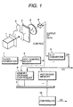
- Fig. 1 is a structural drawing of an X-ray image detecting apparatus of the first embodiment not falling under the claimed invention, in which an X-ray generator 1 emits X-rays toward a subject S in an irradiation direction represented by an arrow and in which a fluorescent screen 2, an optic lens 3, and a CCD image sensor 4 are arranged in order on the opposite side to the generator 1 with respect to the subject S in the irradiation direction of X-rays.
- the output of the CCD image sensor 4 is connected through an A/D converter 5 to an interface to an external device and a memory storage controller 6, and outputs of a clock generator 7 for generating a basic clock, and a CCD control unit 8 are connected in series to the input side of the CCD image sensor 4.
- the output of the CCD control unit 8 is also connected to the memory storage controller 6.
- the memory storage controller 6, a histogram memory 9, and a controller 10 for controlling the entire system are connected to each other through a signal bus 11.
- the CCD image sensor 4 has about six million pixels
- the A/D converter 5 has the 12-bit configuration
- the histogram memory 9 has the 24-bit configuration and 4096 addresses. These addresses correspond to respective gradients, and numerical values stored in the addresses correspond to frequencies of digital values corresponding to the gradients.
- the controller 10 To take an X-ray image in the form of digital data, the controller 10 first outputs a control signal through the signal bus 11 to the histogram memory 9 to initialize all numerical values stored in the histogram memory 9 to zero, and thereafter drives the X-ray generator 1 to generate X-rays.
- X-rays transmitted by the subject S irradiate the fluorescent screen 2, whereby the fluorescent screen 2 radiates beams of fluorescence proportional to intensities of X-rays.
- the optic lens 3 condenses the fluorescence beams on the pixels in the CCD image sensor 4, which stores the light information in the form of charges.
- the CCD control unit 8 outputs control pulses to the CCD image sensor 4 and the memory storage controller 6 in synchronization with the basic clock from the clock generator 7.
- a charge amount in each pixel is output as a voltage value to the A/D converter 5 every control pulse, and the A/D converter 5 converts each voltage value to digital data DD indicating a certain numerical value.
- This digital data DD is transmitted to the interface connected to an external device, also is output as an address value to the memory storage controller 6, and further is stored as image data in a memory device such as a frame memory, not shown.
- the memory storage controller 6 controls the signal bus 11 to take data in from the same address in the histogram memory 9 as an address of each address value in synchronization with the control pulses from the CCD control unit 8, and then adds 1 to the data to again write the result in the same address.
- a numerical value stored in an address in the histogram memory 9 corresponds to a frequency of a gradient represented by the address. Accordingly, an image obtained through the CCD image sensor 4 is converted into a digital image and at the same time as it, a histogram thereof is produced in the histogram memory 9.
- the controller 10 After reading the image data from the memory device not shown, the controller 10 reads the histogram data HD stored in the histogram memory 9 and then outputs it with the image data through the interface to the external device.
- the charge amounts obtained by the CCD image sensor 4 are directly converted into the digital data DD, but they may be converted into the digital data DD after effecting correction of light-quantity unevenness of the fluorescent screen 2, optic lens 3, etc., and correction of variations in conversion efficiency between the pixels in the CCD image sensor 4.
- the A/D converter 5 can be selected not only from those handling 12-bit digital values, but also from those handling arbitrary-number-of-bits digital values. Further, the number of bits of the histogram memory 9 does not always have to be 24 bits. In most cases, a sufficient number is about 16 bits, and thus, the number of bits of the histogram memory 9 can be decreased to this level of bit number. With the thus decreased bit number, the digital values could overflow in the histogram memory 9, and become necessary to be saturated, which will rarely affect the shape of histogram.
- an address in the histogram memory 9 is used for one digital data DD, but the present invention is not limited to such a relation of correspondence.
- a mean value may be obtained from each 50 or so digital data DD for one gradient.
- the histogram can be produced using such mean values as address values, whereby an amount of histogram data HD can be greatly decreased with rarely damaging the shape of histogram.
- this embodiment produced the histogram of the entire image obtained by the CCD image sensor 4, the histogram may be produced of only an image of a portion necessary for diagnosis in order to decrease the data amount of histogram data HD.
- Fig. 2 shows the entire image taken in the CCD image sensor 4, and with respect to this image, a region necessary for diagnosis is only a rectangular portion indicated by the dashed lines, which is a region surrounded by four straight lines Xstart, Ystart, Xend, and Yend.
- position information of the region surrounded by the straight lines Xstart, Ystart, Xend, Yend represented by the dashed lines is preliminarily stored as numbers of control pulses from the CCD control unit 8 in the memory storage controller 6, the memory storage controller 6 counts control pulses from the CCD control unit 8 upon producing the histogram, and based on this pulse number, positions of pixels where the digital data DD output from the A/D converter 5 was obtained are monitored, whereby only data obtained from the pixels inside the dashed lines shown in Fig. 2 out of the digital data DD can be used as address values.
- the present embodiment outputs the shape of histogram as histogram data HD to the outside, but in order to decrease the data amount and to facilitate utilization thereof, it is also possible to output to the outside only a characteristic parameter or characteristic parameters representing the shape of histogram, as extracted from the histogram data HD in the controller 10.
- Fig. 3 is a graph to show histograms, in which the abscissa indicates gradients of 0 to 4095 and the ordinate frequencies of the respective gradients and in which histograms a and b are those obtained from two types of different images.
- the histograms do not have simple shapes like a unimodal shape, but have considerably different shapes between images. Accordingly, it is difficult to uniquely determine a parameter or parameters for expressing the shape of histogram, but they may be extracted depending upon the purpose of use.
- the parameter or parameters may be (1) mean and variance of histogram or standard deviation obtained from these, (2) mode representing a maximum frequency of histogram, (3) width and median of histogram, (4) peak value and frequency thereof roughly taken, etc.
- a look-up table has to be produced in the external arithmetic device in order to display a good-contrast image.
- the apparatus can also be, however, arranged in such a manner that the look-up table optimal to display image data is produced in the controller 10 in the present apparatus, based on the histogram data HD taken from the histogram memory 9. Then, outputting the look-up table with the image data to the external device, it becomes possible to display a good-contrast image with good efficiency.
- the look-up table may be produced depending upon the purpose of use. For example, a look-up table simply will expand gradations of the histograms a, b as shown in Fig. 3 in the direction of the abscissa so as to spread throughout the entire gradient range.
- Fig. 4 is a structural drawing of another embodiment not falling under the claimed invention, which is an image reading apparatus for optically reading an image on an X-ray film taken and developed, different from the embodiment shown in Fig. 1, but having the same circuitry for signal processing as that in the embodiment shown in Fig. 1.
- a transmission-type X-ray film F, an optic lens 22, and a CCD line sensor 23 are arranged in order in the direction of emission from a light source 21 such as a fluorescent lamp or a halogen lamp.
- An output of the CCD line sensor 23 is connected in the same manner as the CCD image sensor 4 shown in Fig. 1 is.
- the CCD line sensor 23 receives a linear image extending in the direction perpendicular to the carrying direction, i.e., an image on the film passing through the portion represented by the chain lines. Accordingly, the X-ray film F is scanned by the CCD line sensor 23 whereby the entire image is read in.
- the CCD control unit 8 produces control pulses, based on the basic clock from the clock generator 7.
- the X-ray film F is carried, charges stored in the CCD line sensor 23 are output as voltage values to the A/D converter 5, the A/D converter 5 converts the voltage values to the digital data DD, the histogram is produced in the same manner as in the above embodiment, and the controller 10 outputs the histogram data with the image data to the outside.
- the X-ray image detecting apparatus and image reading apparatus of the embodiments as described above can produce information concerning the histogram and output it with image data to the external device, they can omit the time and operation for producing the histogram in the external device and can handle a lot of medical images with good efficiency.
- Fig. 5 is a structural drawing of an X-ray image detecting apparatus according to the third embodiment of the claimed invention.
- the present embodiment is constructed substantially in the same structure as the first embodiment except that the apparatus of the present embodiment produces a look-up table based on the histogram data and also performs conversion to digital values for gradation processing of image data based on the look-up table.
- the fluorescent screen 2, optic lens 3, and CCD image sensor 4 are arranged in order on the opposite side to the X-ray generator 1 with respect to the subject S.
- the output of the CCD image sensor 4 is connected through the A/D converter 5 to an image memory 12 and the memory storage controller 6, and the output of the image memory 12 is connected through a gradation-processing look-up table 13 to the interface to the external device.
- Outputs of the clock generator 7 for generating the basic clock, and the CCD control unit 8 are connected in series to the input side of the CCD image sensor 4, and the output of the CCD control unit 8 is also connected to the memory storage controller 6.
- the memory storage controller 6, histogram memory 9, the controller 10 for controlling the entire system, the image memory 12, and the look-up table 13 are connected to each other through the signal bus 11.
- the CCD image sensor 4 has about six million pixels, the A/D converter 5 has the 12-bit configuration, and the histogram memory 9 has the 24-bit configuration and 4096 addresses. These addresses correspond to respective gradients, and numerical values stored in the addresses correspond to frequencies of digital values corresponding to the gradients.
- the image memory 12 has a capacity of 2000 ⁇ 3000 ⁇ 12 bits, and the look-up table 13 has the 12-bit configuration and 4096 addresses.
- the controller 10 In order to read an X-ray image in as digital data, the controller 10 first outputs a control signal through the signal bus 11 to the histogram memory 9 to initialize all numerical values stored in the histogram memory 9 to zero, and thereafter drives the X-ray generator 1 to generate X-rays.
- X-rays transmitted by the subject S irradiate the fluorescent screen 2, and then the fluorescent screen 2 emits beams of fluorescence proportional to intensities of X-rays.
- the beams of fluorescence are condensed by the optic lens 3 to be received by the CCD image sensor 4, which stores charges according to the received beams.
- the CCD control unit 8 outputs the control pulses to the CCD image sensor 4 and the memory storage controller 6 in synchronization with the basic clock from the clock generator 7.
- the charge amounts in the respective pixels are output as voltage values one every control pulse to the A/D converter 5, and the A/D converter 5 converts each voltage value to digital data DD indicating a certain numerical value.
- the digital data DD is sent to the image memory 12, which stores the data and also outputs it as address values to the memory storage controller 6.
- the memory storage controller 6 controls the signal bus 11 to read data from the same address in the histogram memory 9 as an address of each address value in synchronization with the control pulses from the CCD control unit 8, and adds 1 to this data and again writes the result in the same address.
- Numerical values accumulated in the respective addresses in the histogram memory 9 correspond to frequencies of the gradients represented by the addresses. Accordingly, an image obtained through the CCD image sensor 4 is converted into a digital image, and at the same time as it, the histogram memory 9 produces the histogram.
- the controller 10 After reading the X-ray image, the controller 10 reads the histogram data HD stored in the histogram memory 9, writes look-up table data in the look-up table 13, based on the histogram data HD, and then outputs the image data held in the image memory 12 to the external interface after data conversion through the look-up table 13.
- the apparatus of the present embodiment has the functions to produce the histogram data from the image data and to determine the look-up table data from the histogram data and is arranged to output to the external device the image data after digital conversion referring to the look-up table data, the load on the external device is greatly decreased, the operation efficiency is more improved, and the processing speed is increased.
- the charge amounts obtained by the CCD image sensor 4 are directly converted into the digital data DD, but they may be converted into the digital data DD after effecting correction of light-quantity unevenness of the fluorescent screen 2, optic lens 3, etc., and correction of variations in conversion efficiency between the pixels in the CCD image sensor 4.
- the A/D converter 5 can be selected not only from those handling 12-bit digital values, but also from those handling arbitrary-number-of-bits digital values. Further, the number of bits of the histogram memory 9 does not always have to be 24 bits. In most cases, a sufficient number is about 16 bits, and thus, the number of bits of the histogram memory 9 can be decreased to this level of bit number. With the thus decreased bit number, the digital values could overflow in the histogram memory 9, and become necessary to be saturated, which will rarely affect the shape of histogram.
- the capacity of the image memory 12 does not always have to be 2000 ⁇ 3000 ⁇ 12 bits, but may be determined to be an arbitrary capacity depending upon the size of image, the number of images, etc. Further, the number of bits of the look-up table 13 does not always have to be 12 bits, but can be set to an arbitrary number of bits matching the number of necessary gradients.
- an address in the histogram memory 9 is used for one digital data DD, but the present invention is not limited to such a relation of correspondence.
- a mean value may be obtained from each 50 or so digital data DD for one gradient.
- the histogram can be produced using such mean values as address values, whereby an amount of histogram data HD can be greatly decreased with rarely damaging the shape of histogram.
- this embodiment produced the histogram of the entire image obtained by the CCD image sensor 4, the histogram may be produced of only an image of a portion necessary for diagnosis in order to decrease the data amount of histogram data HD, as explained with Fig. 2, and it can be used for the look-up table.
- the present embodiment can output the information concerning the histogram, such as the look-up table data and the histogram data HD, as the data having been used in the gradation processing, to the external device as added to the image or separated from the image.
- the information concerning the histogram such as the look-up table data and the histogram data HD, as the data having been used in the gradation processing
- the controller 10 may be arranged to extract only a characteristic parameter or characteristic parameters representing the shape of histogram from the histogram data HD to output it or them, as explained with Fig. 3.
- the apparatus may also have an additional function to output to the external device the information concerning the histogram, or the look-up table data before the image data.
- the look-up table can be preliminarily prepared in the external device, and the image data can be taken in not through the look-up table in the apparatus, but through the look-up table in the external device. This can cut a memory for temporarily holding the image in the external device, the time for producing the information concerning the histogram, etc.
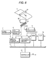
- Fig. 6 is a structural drawing of another embodiment according to the claimed invention. Different from the embodiment shown in Fig. 5, the present embodiment is an image reading apparatus for optically reading an image on an X-ray film taken and developed, similar to the embodiment of Fig. 4. However, the signal processing circuitry is the same as that in the embodiment shown in Fig. 5.
- the transmission-type X-ray film F, optic lens 22, and CCD line sensor 23 are arranged in order.
- the output of the CCD line sensor 23 is connected in the same manner as the CCD image sensor 4 shown in Fig. 5 is.
- the light from the light source 21 is transmitted by the X-ray film F and then is condensed by the optic lens 22 to be focused on the CCD line sensor 23. Since the X-ray film F is successively carried in the direction of the arrow by a carrier not shown, the CCD line sensor 23 receives a linear image in the direction perpendicular to the carrying direction, i.e., an image on the film passing the portion indicated by the chain lines. Accordingly, the X-ray film F is scanned by the CCD line sensor 23 whereby the entire image is read in.
- the CCD control unit 8 produces the control pulses, based on the basic clock from the clock generator 7.
- the X-ray film F is carried in synchronization with the control pulses, and the CCD line sensor 23 outputs charges stored therein as voltage values to the A/D converter 5, which converts the voltage values to the digital data DD.
- the controller 10 writes the look-up table data based on the histogram data in the look-up table 13, and the image data held in the image memory 12 is output through the look-up table 13 to the external interface.
- the X-ray image detecting apparatus and image reading apparatus are arranged to produce the information concerning the histogram, to produce the look-up table based on the histogram data, to perform the gradation processing in the apparatus, and to output the image data after gradation processing to the external device, it can omit the operation and time for processing the histogram in the external device and the operation and time for performing the gradation processing of image data, and it can handle a lot of medical images with good efficiency and at low cost.
Landscapes
- Engineering & Computer Science (AREA)
- Multimedia (AREA)
- Signal Processing (AREA)
- Image Processing (AREA)
- Facsimile Image Signal Circuits (AREA)
- Image Analysis (AREA)
- Transforming Light Signals Into Electric Signals (AREA)
- Radiography Using Non-Light Waves (AREA)
- Apparatus For Radiation Diagnosis (AREA)
- Closed-Circuit Television Systems (AREA)
Claims (3)
- Vorrichtung zum Aufnehmen eines Bilds, mit:wobei durch das Datenwandlungssystem (13) gewandelte Bilddaten zu der externen Vorrichtung ausgegeben werden und die ein Histogramm betreffenden Daten (HD) derart zu der externen Vorrichtung ausgegeben werden, daß die ein Histogramm betreffenden Daten (HD) zu den durch das Datenwandlungssystem (13) gewandelten Bilddaten hinzugefügt oder von ihnen getrennt ausgegeben werden.einem Bildleseabschnitt (2-5; 22, 23) zum Ausgeben von Bilddaten (DD) eines gelesenen Bilds; undeinem Signalverarbeitungsabschnitt (6, 9, 10; 12) zum Empfangen der Bilddaten (DD) von dem Bildleseabschnitt (2-5; 22, 23) und Ausgeben eines Signals zu einer externen Vorrichtung, wobei der Signalverarbeitungsabschnitt (6, 9, 10; 12) umfaßt:ein Histogrammsystem (6, 9, 10) zum Erzeugen von ein Histogramm betreffenden Daten (HD) aus den Bilddaten (DD) von dem Bildleseabschnitt (2-5; 22, 23); undein Datenwandlungssystem (13) zum Wandeln der Bilddaten (DD) von dem Bildleseabschnitt (2-5; 22, 23) auf der Grundlage der ein Histogramm betreffenden Daten (HD) ;
- Vorrichtung nach Anspruch 1, wobei das Histogrammsystem (6, 9, 10) Daten eines eine Form eines Histogramms der Bilddaten (DD) betreffenden Parameters, ein Histogramm eines Teils der Bilddaten (DD) betreffende Daten, ein Histogramm mit einer geringeren Anzahl von Daten als einer Anzahl von Daten der Bilddaten (DD), Daten eines Histogramms der Bilddaten (DD) selbst und/oder Daten einer Nachschlagetabelle zur Bildanzeige als die ein Histogramm betreffenden Daten (HD) erzeugt.
- Vorrichtung nach Anspruch 1, wobei der Bildleseabschnitt (2-5; 22, 23) ein Röntgenbild erfaßt oder ein Bild eines Films (F) aufnimmt.
Priority Applications (1)
| Application Number | Priority Date | Filing Date | Title |
|---|---|---|---|
| EP02015930A EP1251685B1 (de) | 1994-09-21 | 1995-09-20 | Vorrichtung zum Nachweis von Röntgenstrahlung und Bildlesegerät |
Applications Claiming Priority (6)
| Application Number | Priority Date | Filing Date | Title |
|---|---|---|---|
| JP25464794 | 1994-09-21 | ||
| JP25464794 | 1994-09-21 | ||
| JP254647/94 | 1994-09-21 | ||
| JP25695795 | 1995-09-08 | ||
| JP7256957A JPH08147456A (ja) | 1994-09-21 | 1995-09-08 | X線画像検出装置及び画像読取装置 |
| JP256957/95 | 1995-09-08 |
Related Child Applications (1)
| Application Number | Title | Priority Date | Filing Date |
|---|---|---|---|
| EP02015930A Division EP1251685B1 (de) | 1994-09-21 | 1995-09-20 | Vorrichtung zum Nachweis von Röntgenstrahlung und Bildlesegerät |
Publications (3)
| Publication Number | Publication Date |
|---|---|
| EP0703699A2 EP0703699A2 (de) | 1996-03-27 |
| EP0703699A3 EP0703699A3 (de) | 1996-08-14 |
| EP0703699B1 true EP0703699B1 (de) | 2003-12-03 |
Family
ID=26541774
Family Applications (2)
| Application Number | Title | Priority Date | Filing Date |
|---|---|---|---|
| EP95114815A Expired - Lifetime EP0703699B1 (de) | 1994-09-21 | 1995-09-20 | Vorrichtung zum Nachweis von Röntgenstrahlung und Bildlesegerät |
| EP02015930A Expired - Lifetime EP1251685B1 (de) | 1994-09-21 | 1995-09-20 | Vorrichtung zum Nachweis von Röntgenstrahlung und Bildlesegerät |
Family Applications After (1)
| Application Number | Title | Priority Date | Filing Date |
|---|---|---|---|
| EP02015930A Expired - Lifetime EP1251685B1 (de) | 1994-09-21 | 1995-09-20 | Vorrichtung zum Nachweis von Röntgenstrahlung und Bildlesegerät |
Country Status (3)
| Country | Link |
|---|---|
| EP (2) | EP0703699B1 (de) |
| JP (1) | JPH08147456A (de) |
| DE (2) | DE69534998D1 (de) |
Families Citing this family (2)
| Publication number | Priority date | Publication date | Assignee | Title |
|---|---|---|---|---|
| DE19731303B4 (de) * | 1997-07-13 | 2009-02-26 | Smi Senso Motoric Instruments Gmbh | Verfahren und Vorrichtung zum kontaktlosen, helmfreien Messen der Blickrichtung von Augen bei Kopf- und Augenbewegungen |
| JP5489577B2 (ja) | 2009-07-31 | 2014-05-14 | キヤノン株式会社 | 放射線撮像システム及びその制御方法、メイン制御ユニット及びその制御方法、並びに、プログラム |
Citations (1)
| Publication number | Priority date | Publication date | Assignee | Title |
|---|---|---|---|---|
| EP0560165A1 (de) * | 1992-02-28 | 1993-09-15 | Eastman Kodak Company | Bildabtastsystem und Verfahren zu verbesserter Mikrofilmbildqualität |
Family Cites Families (2)
| Publication number | Priority date | Publication date | Assignee | Title |
|---|---|---|---|---|
| JP2779496B2 (ja) * | 1988-03-14 | 1998-07-23 | 富士写真フイルム株式会社 | 放射線画像読取表示装置 |
| JP2525859B2 (ja) * | 1988-03-31 | 1996-08-21 | 大日本スクリーン製造株式会社 | ハイライト・シャド―濃度値の設定方法 |
-
1995
- 1995-09-08 JP JP7256957A patent/JPH08147456A/ja active Pending
- 1995-09-20 EP EP95114815A patent/EP0703699B1/de not_active Expired - Lifetime
- 1995-09-20 DE DE69534998T patent/DE69534998D1/de not_active Expired - Lifetime
- 1995-09-20 DE DE1995632225 patent/DE69532225T2/de not_active Expired - Lifetime
- 1995-09-20 EP EP02015930A patent/EP1251685B1/de not_active Expired - Lifetime
Patent Citations (1)
| Publication number | Priority date | Publication date | Assignee | Title |
|---|---|---|---|---|
| EP0560165A1 (de) * | 1992-02-28 | 1993-09-15 | Eastman Kodak Company | Bildabtastsystem und Verfahren zu verbesserter Mikrofilmbildqualität |
Non-Patent Citations (1)
| Title |
|---|
| GONZALEZ, RAFAEL C.: "Digital Image Processing", 30 June 1992, ADDISON-WESLEY PUBLISHING COMPANY, UNITED STATES OF AMERICA * |
Also Published As
| Publication number | Publication date |
|---|---|
| EP1251685A3 (de) | 2003-01-08 |
| DE69532225D1 (de) | 2004-01-15 |
| EP1251685A2 (de) | 2002-10-23 |
| DE69534998D1 (de) | 2006-06-22 |
| EP1251685B1 (de) | 2006-05-17 |
| DE69532225T2 (de) | 2004-10-07 |
| EP0703699A3 (de) | 1996-08-14 |
| JPH08147456A (ja) | 1996-06-07 |
| EP0703699A2 (de) | 1996-03-27 |
Similar Documents
| Publication | Publication Date | Title |
|---|---|---|
| US4774569A (en) | Method for adaptively masking off a video window in an overscanned image | |
| JP2716755B2 (ja) | アドレス・トークンに基づく画像処理装置 | |
| EP0331687B1 (de) | Apparat und verfahren zum lokalisieren von rändern und vorlagengrenzlinien in videoabtastzeilen | |
| US6370265B1 (en) | Method for generating gray scale transfer functions for use in displaying a digital radiogram | |
| US7729019B2 (en) | Image reading system and image reading program | |
| JPH0254683A (ja) | 画像走査装置およびその補正方法 | |
| JPH07153592A (ja) | 自動x線露光装置の作動方法および自動x線露光装置 | |
| US6249596B1 (en) | Method of locating saturated pixels in the display of a radiographic image | |
| US4903141A (en) | Apparatus for electronically duplicating film images while maintaining a high degree of image quality | |
| US6219405B1 (en) | Method and apparatus for sensing an image | |
| US6477228B2 (en) | Method for operating an X-ray diagnosis device with immediate imaging | |
| US4965679A (en) | Method for electronically duplicating film images while maintaining a high degree of image quality | |
| US6282306B1 (en) | X-ray image detecting apparatus and image reading apparatus | |
| JP2004053584A (ja) | 画像補正装置及び方法 | |
| EP0703699B1 (de) | Vorrichtung zum Nachweis von Röntgenstrahlung und Bildlesegerät | |
| US4724489A (en) | Electronic image generation | |
| JPH05293095A (ja) | 画像表示方法 | |
| EP0219575A1 (de) | Verfahren zur Korrektur eines Videoausgangssignals | |
| US6891965B2 (en) | Image display method and apparatus | |
| US6212293B1 (en) | Image reading device | |
| US6201618B1 (en) | Image reading device | |
| JPS63298578A (ja) | 表面分析用画像表示装置 | |
| EP0166922B1 (de) | Verfahren und Vorrichtung zum Auslesen eines Strahlungsbildes | |
| JP2814769B2 (ja) | 画像処理装置 | |
| JPH01261787A (ja) | 放射線画像処理装置 |
Legal Events
| Date | Code | Title | Description |
|---|---|---|---|
| PUAI | Public reference made under article 153(3) epc to a published international application that has entered the european phase |
Free format text: ORIGINAL CODE: 0009012 |
|
| AK | Designated contracting states |
Kind code of ref document: A2 Designated state(s): DE FR GB NL |
|
| PUAL | Search report despatched |
Free format text: ORIGINAL CODE: 0009013 |
|
| AK | Designated contracting states |
Kind code of ref document: A3 Designated state(s): DE FR GB NL |
|
| 17P | Request for examination filed |
Effective date: 19970102 |
|
| 17Q | First examination report despatched |
Effective date: 19980930 |
|
| APAB | Appeal dossier modified |
Free format text: ORIGINAL CODE: EPIDOS NOAPE |
|
| GRAH | Despatch of communication of intention to grant a patent |
Free format text: ORIGINAL CODE: EPIDOS IGRA |
|
| GRAH | Despatch of communication of intention to grant a patent |
Free format text: ORIGINAL CODE: EPIDOS IGRA |
|
| GRAA | (expected) grant |
Free format text: ORIGINAL CODE: 0009210 |
|
| AK | Designated contracting states |
Kind code of ref document: B1 Designated state(s): DE FR GB NL |
|
| REG | Reference to a national code |
Ref country code: GB Ref legal event code: FG4D |
|
| REF | Corresponds to: |
Ref document number: 69532225 Country of ref document: DE Date of ref document: 20040115 Kind code of ref document: P |
|
| ET | Fr: translation filed | ||
| PLBE | No opposition filed within time limit |
Free format text: ORIGINAL CODE: 0009261 |
|
| STAA | Information on the status of an ep patent application or granted ep patent |
Free format text: STATUS: NO OPPOSITION FILED WITHIN TIME LIMIT |
|
| 26N | No opposition filed |
Effective date: 20040906 |
|
| PGFP | Annual fee paid to national office [announced via postgrant information from national office to epo] |
Ref country code: NL Payment date: 20080915 Year of fee payment: 14 |
|
| PGFP | Annual fee paid to national office [announced via postgrant information from national office to epo] |
Ref country code: FR Payment date: 20080923 Year of fee payment: 14 |
|
| REG | Reference to a national code |
Ref country code: NL Ref legal event code: V1 Effective date: 20100401 |
|
| REG | Reference to a national code |
Ref country code: FR Ref legal event code: ST Effective date: 20100531 |
|
| PG25 | Lapsed in a contracting state [announced via postgrant information from national office to epo] |
Ref country code: NL Free format text: LAPSE BECAUSE OF NON-PAYMENT OF DUE FEES Effective date: 20100401 Ref country code: FR Free format text: LAPSE BECAUSE OF NON-PAYMENT OF DUE FEES Effective date: 20090930 |
|
| PGFP | Annual fee paid to national office [announced via postgrant information from national office to epo] |
Ref country code: DE Payment date: 20130930 Year of fee payment: 19 |
|
| PGFP | Annual fee paid to national office [announced via postgrant information from national office to epo] |
Ref country code: GB Payment date: 20130924 Year of fee payment: 19 |
|
| REG | Reference to a national code |
Ref country code: DE Ref legal event code: R119 Ref document number: 69532225 Country of ref document: DE |
|
| GBPC | Gb: european patent ceased through non-payment of renewal fee |
Effective date: 20140920 |
|
| REG | Reference to a national code |
Ref country code: DE Ref legal event code: R119 Ref document number: 69532225 Country of ref document: DE Effective date: 20150401 |
|
| PG25 | Lapsed in a contracting state [announced via postgrant information from national office to epo] |
Ref country code: GB Free format text: LAPSE BECAUSE OF NON-PAYMENT OF DUE FEES Effective date: 20140920 Ref country code: DE Free format text: LAPSE BECAUSE OF NON-PAYMENT OF DUE FEES Effective date: 20150401 |