EP0703386A2 - Control system for a positive displacement machine of a hydromechanic power-shift transmission - Google Patents
Control system for a positive displacement machine of a hydromechanic power-shift transmission Download PDFInfo
- Publication number
- EP0703386A2 EP0703386A2 EP95113359A EP95113359A EP0703386A2 EP 0703386 A2 EP0703386 A2 EP 0703386A2 EP 95113359 A EP95113359 A EP 95113359A EP 95113359 A EP95113359 A EP 95113359A EP 0703386 A2 EP0703386 A2 EP 0703386A2
- Authority
- EP
- European Patent Office
- Prior art keywords
- clutch
- gear
- volume
- position signal
- control device
- Prior art date
- Legal status (The legal status is an assumption and is not a legal conclusion. Google has not performed a legal analysis and makes no representation as to the accuracy of the status listed.)
- Granted
Links
Images

Classifications
-
- F—MECHANICAL ENGINEERING; LIGHTING; HEATING; WEAPONS; BLASTING
- F16—ENGINEERING ELEMENTS AND UNITS; GENERAL MEASURES FOR PRODUCING AND MAINTAINING EFFECTIVE FUNCTIONING OF MACHINES OR INSTALLATIONS; THERMAL INSULATION IN GENERAL
- F16H—GEARING
- F16H47/00—Combinations of mechanical gearing with fluid clutches or fluid gearing
- F16H47/02—Combinations of mechanical gearing with fluid clutches or fluid gearing the fluid gearing being of the volumetric type
- F16H47/04—Combinations of mechanical gearing with fluid clutches or fluid gearing the fluid gearing being of the volumetric type the mechanical gearing being of the type with members having orbital motion
-
- F—MECHANICAL ENGINEERING; LIGHTING; HEATING; WEAPONS; BLASTING
- F16—ENGINEERING ELEMENTS AND UNITS; GENERAL MEASURES FOR PRODUCING AND MAINTAINING EFFECTIVE FUNCTIONING OF MACHINES OR INSTALLATIONS; THERMAL INSULATION IN GENERAL
- F16H—GEARING
- F16H61/00—Control functions within control units of change-speed- or reversing-gearings for conveying rotary motion ; Control of exclusively fluid gearing, friction gearing, gearings with endless flexible members or other particular types of gearing
- F16H61/38—Control of exclusively fluid gearing
- F16H61/40—Control of exclusively fluid gearing hydrostatic
- F16H61/46—Automatic regulation in accordance with output requirements
- F16H61/462—Automatic regulation in accordance with output requirements for achieving a target speed ratio
-
- F—MECHANICAL ENGINEERING; LIGHTING; HEATING; WEAPONS; BLASTING
- F16—ENGINEERING ELEMENTS AND UNITS; GENERAL MEASURES FOR PRODUCING AND MAINTAINING EFFECTIVE FUNCTIONING OF MACHINES OR INSTALLATIONS; THERMAL INSULATION IN GENERAL
- F16H—GEARING
- F16H37/00—Combinations of mechanical gearings, not provided for in groups F16H1/00 - F16H35/00
- F16H37/02—Combinations of mechanical gearings, not provided for in groups F16H1/00 - F16H35/00 comprising essentially only toothed or friction gearings
- F16H37/06—Combinations of mechanical gearings, not provided for in groups F16H1/00 - F16H35/00 comprising essentially only toothed or friction gearings with a plurality of driving or driven shafts; with arrangements for dividing torque between two or more intermediate shafts
- F16H37/08—Combinations of mechanical gearings, not provided for in groups F16H1/00 - F16H35/00 comprising essentially only toothed or friction gearings with a plurality of driving or driven shafts; with arrangements for dividing torque between two or more intermediate shafts with differential gearing
- F16H37/0833—Combinations of mechanical gearings, not provided for in groups F16H1/00 - F16H35/00 comprising essentially only toothed or friction gearings with a plurality of driving or driven shafts; with arrangements for dividing torque between two or more intermediate shafts with differential gearing with arrangements for dividing torque between two or more intermediate shafts, i.e. with two or more internal power paths
- F16H37/084—Combinations of mechanical gearings, not provided for in groups F16H1/00 - F16H35/00 comprising essentially only toothed or friction gearings with a plurality of driving or driven shafts; with arrangements for dividing torque between two or more intermediate shafts with differential gearing with arrangements for dividing torque between two or more intermediate shafts, i.e. with two or more internal power paths at least one power path being a continuously variable transmission, i.e. CVT
- F16H2037/088—Power split variators with summing differentials, with the input of the CVT connected or connectable to the input shaft
- F16H2037/0886—Power split variators with summing differentials, with the input of the CVT connected or connectable to the input shaft with switching means, e.g. to change ranges
-
- Y—GENERAL TAGGING OF NEW TECHNOLOGICAL DEVELOPMENTS; GENERAL TAGGING OF CROSS-SECTIONAL TECHNOLOGIES SPANNING OVER SEVERAL SECTIONS OF THE IPC; TECHNICAL SUBJECTS COVERED BY FORMER USPC CROSS-REFERENCE ART COLLECTIONS [XRACs] AND DIGESTS
- Y10—TECHNICAL SUBJECTS COVERED BY FORMER USPC
- Y10T—TECHNICAL SUBJECTS COVERED BY FORMER US CLASSIFICATION
- Y10T74/00—Machine element or mechanism
- Y10T74/19—Gearing
- Y10T74/19149—Gearing with fluid drive
- Y10T74/19158—Gearing with fluid drive with one or more controllers for gearing, fluid drive, or clutch
- Y10T74/19163—Gearing with fluid drive with one or more controllers for gearing, fluid drive, or clutch with interrelated controls
Definitions
- the invention relates to a method for controlling a hydrostatic variable transmission of a hydrostatic-mechanically stepless power-split power shift transmission in which a displacer volume is changed for a gear change until a predetermined speed ratio of a transmission input shaft speed to an output shaft speed is present, after which a clutch of a new gear is engaged , and then the displacer volume is changed with respect to a theoretical displacer volume in the direction of a new displacer volume, in which the clutch of the still moving, previously effective gear is relieved, after which it is disengaged.
- the displacement volume is carried out by pivoting an abutment which is electrically controlled by means of a proportional hydraulic adjusting device.
- the positive displacement machine is used in an additive manner to transmit power before shifting up a gear stage and subtractively after shifting into higher gear.
- theoretically synchronous speeds are to be engaged and disengaged Clutches predefined so that the clutch of the new gear is switched on smoothly and the clutch of the previous gear is disengaged smoothly thereafter.
- the hydrostatic transmission is controlled in such a way that the leakage losses are also covered before the new gear is engaged to produce the synchronous operation on the clutch.
- the corrective setting results in each case independently of the respective pressure ratios and thus the corresponding leakage losses, which differ depending on the branching ratio used in the upper speed range of the lower gear and in the lower speed range of the upper gear by the switching ratio. For this reason, the leakage losses before an upshift in the synchronous state of the clutch to be engaged are smaller than after an upshift when the clutch is disengaged. When shifting down, the loss ratios are reversed. According to the invention, these differences in leakage losses before and after switching are taken into account in the setting of the displacer volume, so that a disengagement is only carried out when no torque is transmitted via the coupling parts, which is caused by the beginning Movement of the coupling parts is signaled at the correct displacement volume setting.
- a control circuit for setting the displacer volume to which a position signal of the actuating device of the displacer volume is supplied as an actual displacer signal. Furthermore, it is provided that speed signals are taken from the drive and output shafts of the hydrostatic transmission unit in a known manner. By observing the speed ratios known for the individual gears, it can thereby be achieved that the next desired gear is engaged with a synchronism on the clutch. In the direction of the theoretical displacement position signal and beyond, a set position signal to be specified for the displacement control is now continuously formed, so that the different leakage oil losses for the new transmission branch are increasingly taken into account.
- Displacer volume is continuously regulated according to an operating specification.
- This regulation and control of the hydraulic system and the couplings described above also brings about an adaptation of the hydraulic setting when disengaging to the leakage behavior of the device, which changes with ongoing operation and which depends on the temperature of the hydraulic oil and which depends on the actuator and also changes with the load.
- Fig. 1 shows a hydrostatic-mechanical power split power shift transmission, the hydrostatic branch of which consists of the hydrostatic actuator (HG).
- HG hydrostatic actuator
- ST electronic control device
- HGZ position-proportional hydraulic control cylinder
- HV electric-hydraulic control valve pair
- the presence of this speed ratio is determined from the signals from the speed sensors (S1, S2) in the electronic control device (ST). is determined, actuated by the control device (ST) the electrohydraulic third-gear valve (V3), which allows the third-gear clutch (K3) to engage hydraulically, the determined Speed ratio ensures that the gear parts of the clutch (K3) of the third gear rotate synchronously before coupling.
- the proportional device (HGZ) is acted upon by the control device (ST) via the electrohydraulic control valve (HGV) in such a way that it is continuously corrected according to the leakage losses that are different for torque-free disengagement, up to the coupling clutch claws of the second clutch (K2) Gear transmission no more torque is transmitted.
- the control device (ST) switches off the second-gear valve (V2) and thereby disengages the second-gear clutch (K2) hydraulically without jerking by switching off the associated controllable valve (V2).
- the torque free on the clutch (K2) is determined by continuously monitoring the signal of the clutch position sensor (KS2) for an occurring position change from the control device (ST) when the clutch (K2) is acted on in the separating direction.
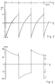
- Fig. 3 shows the pressure conditions in the hydrostatic branch.
- the two pressures (P1, P2) on both sides of the switching point are related to each other like the control ratio.
- the proportional valve unit For the exact adjustability of the proportional valve unit (HGV), it is fed with a predeterminable current from the control device (ST). This current is preferably reported back to the control device (ST) by a current sensor as an actual displacement position signal.
- a position indicator e.g. of a potentiometer (P) on the wiper side
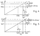
- the old displacement volume (Valt) that prevails when the clutch is engaged is larger than the theoretical displacement volume (Vth) by the leakage volume (DValt).
- the new displacer volume (Vneu), in which the old gearbox is load-free, is smaller by a leakage volume difference (DValt xk) than the theoretical displacer volume (Vth) by the leakage volume factor (k). Accordingly, the old and new settings (Salt, Sneu) are higher and lower than the theoretical position (Sth) by a smaller or a larger amount.
- the leakage volume factor is in principle greater than 1, since different pressure conditions prevail in the old and new condition, which lead to the differences.
- the clutch position sensors (KS2, KS3) are, for example, commercially available rotary potentiometers which are arranged on the actuating shafts of the swivel claws. The working range of these potentiometers is expediently somewhat larger than the swivel angle of the swivel claws between the engaged and disengaged condition of the connected couplings.
- the two sensor signal values of the voltage-fed potentiometers, which each occur in the clutch positions, are stored by the control device and used as comparison values, a tolerance variable being appropriately taken into account.
- the saving of the final values can be repeated after each coupling process and the value can be adapted to any fluctuations.
- the position sensors of the clutches are also used to monitor the correct function of the clutch and its actuating means, which was also common up to now.
- the determination of the correct disengagement conditions by means of the clutch position sensor signals is a new additional use of the same.
Landscapes
- Engineering & Computer Science (AREA)
- General Engineering & Computer Science (AREA)
- Mechanical Engineering (AREA)
- Control Of Transmission Device (AREA)
- Hydraulic Clutches, Magnetic Clutches, Fluid Clutches, And Fluid Joints (AREA)
- Control Of Fluid Gearings (AREA)
Abstract
Description
Die Erfindung betrifft ein Verfahren zur Steuerung eines hydrostatischen Verstellgetriebes eines hydrostatisch-mechanisch stufenlos leistungsverzweigten Lastschaltgetriebes bei dem zu einem Gangwechsel ein Verdrängervolumen jeweils so lange geändert wird, bis ein vorgegebenes Drehzahlverhältnis einer Getriebeeingangswellendrehzahl zu einer Ausgangswellendrehzahl vorliegt, wonach ein Einschalten einer Kupplung eines neuen Ganges erfolgt, und dann das Verdrängervolumen bezüglich eines theoretischen Verdrängervolumens in Richtung auf ein neues Verdrängervolumen geändert wird, bei dem die Kupplung des jeweils noch mitlaufenden, vorher wirksamen Ganges entlastet wird, wonach diese ausgerückt wird.The invention relates to a method for controlling a hydrostatic variable transmission of a hydrostatic-mechanically stepless power-split power shift transmission in which a displacer volume is changed for a gear change until a predetermined speed ratio of a transmission input shaft speed to an output shaft speed is present, after which a clutch of a new gear is engaged , and then the displacer volume is changed with respect to a theoretical displacer volume in the direction of a new displacer volume, in which the clutch of the still moving, previously effective gear is relieved, after which it is disengaged.
Aus der DE 38 38 767 C2 ist eine derartige Steuerung einer Verdrängermaschine bekannt, bei der jeweils beim Gangwechsel eine Einstellung des Verdrängervolumens entsprechend dem theoretischen Ölbedarf zuzüglich eines bestimmten Leckageverlustes erfolgt, damit jeweils die auszurückende Kupplung des vorherigen Ganges möglichst drehmomentlos zu schalten ist. Die Bestimmung eines zu berücksichtigenden Leckageverlustes aufgrund früherer Meßwerte und theoretischer Betrachtungen gibt einen ungenauen Kompromiß, da die Verdrängermaschine vor und nach den Schaltpunkten aufeinanderfolgender Getriebestufen jeweils entsprechend der Getriebestufung mit einem unterschiedlichen hydraulischen Übertragungsanteil wirksam ist, so daß die hydraulischen Druckverhältnisse und demzufolge das Verhältnis der Leckageverluste unterschiedlich groß ist, was stets unberückischtigt geblieben ist, so daß das beabsichtigte drehmomentarme Ausrückenden der Kupplungsteile entweder in keinem Fall oder nur bei dem Hoch- oder dem Herunterschalten erreicht wird, was zu Schäden an der Kupplung und dem Getriebe und ruckartigem Betrieb führt.Such a control of a displacement machine is known from DE 38 38 767 C2, in which when the gear is changed, the displacement volume is adjusted according to the theoretical oil requirement plus a certain leakage loss, so that the clutch to be disengaged from the previous gear is to be switched as torque-free as possible. The determination of a leakage loss to be taken into account on the basis of previous measured values and theoretical considerations gives an imprecise compromise, since the displacement machine before and after the switching points of successive gear stages is effective with a different hydraulic transmission component, depending on the gear ratio, so that the hydraulic pressure ratios and consequently the ratio of the leakage losses is of different sizes, which has always remained undiminished, so that the intended Low torque disengaging ends of the clutch parts are either never reached or only when shifting up or down, which leads to damage to the clutch and the transmission and jerky operation.
Es ist Aufgabe der Erfindung, eine Steuerung der Verdrängermaschine zu offenbaren, bei der bei jedem Schaltvorgang eine drehmomentlose Einstellung der auszurückenden Kupplungsteile zuverlässig und für eine zum vollständigen Auskuppeln ausreichende Zeit erreicht wird.It is an object of the invention to disclose a control of the displacement machine, in which a torque-free adjustment of the clutch parts to be disengaged is achieved reliably and for a time sufficient for complete disengagement with each shift.
Die Lösung der Aufgabe besteht darin, daß jeweils während dieser Änderung des Verdrängervolumens die Kupplung des jeweils noch mitlaufenden, vorher wirksamen Ganges in Ausrückrichtung angesteuert wird und dabei ein Kupplungsstellungssignal laufend darauf überwacht wird, ob ein Ausrücken beginnt, und wenn dies der Fall ist, das erreichte Verdrängervolumen konstant gehalten wird, bis ein vollständiges Ausrücken der betreffenden Kupplung durch das Kupplungsstellungssignal gemeldet wird.The solution to the problem is that during this change in the displacement volume, the clutch of the still active, previously active gear is actuated in the disengaging direction and a clutch position signal is continuously monitored for whether disengagement begins, and if this is the case, that reached displacer volume is kept constant until a complete disengagement of the clutch concerned is reported by the clutch position signal.
Vorteilhafte Ausgestaltung sind in den Unteransprüchen angegeben.An advantageous embodiment is specified in the subclaims.
Bei den bekannten Verdrängermaschinen wird das Verdrängervolumen durch eine Schwenkverstellung eines Widerlagers vorgenommen, die mittels einer proportional wirkenden hydraulischen Verstelleinrichtung elektrisch gesteuert erfolgt. In einem stufenlosen, hydrostatischleistungsverzweigten Getriebe wird die Verdrängermaschine jeweils vor dem Heraufschalten einer Getriebestufe additiv leistungsübertragend und nach dem Umschalten in den höheren Gang subtraktiv genutzt. In beiden Fällen sind theoretisch synchrone Drehzahlen an den ein- und auszurückenden Kupplungen vorgegeben, damit ein ruckfreies Einschalten der Kupplung des neuen Ganges ebenso wie ein ruckfreies Ausrücken der Kupplung des vorherigen Ganges danach erfolgt. Im praktischen Betrieb ist es nun erforderlich, daß vor dem Einkuppeln des neuen Ganges zur Herstellung des Synchronlaufes an der Kupplung das hydrostatische Getriebe so gesteuert ist, daß auch dessen Leckageverluste gedeckt sind. Da nach dem Einschalten des neuen Ganges wegen der inversen Betriebsweise des Hydraulikgetriebes wieder Leckageverluste bezüglich der konstant arbeitenden Verdrängereinheit auftreten, ist es zur Einstellung einer Drehmomentfreiheit an der auszurückenden Kupplung erforderlich, eine korrigierende, diese Verhältnisse berücksichtigende, Umsteuerung des Verdrängervolumens vorzunehmen, wobei die unterschiedlichen Leckageverluste zu berücksichtigen sind.In the known displacement machines, the displacement volume is carried out by pivoting an abutment which is electrically controlled by means of a proportional hydraulic adjusting device. In a continuously variable, hydrostatic power-split transmission, the positive displacement machine is used in an additive manner to transmit power before shifting up a gear stage and subtractively after shifting into higher gear. In both cases, theoretically synchronous speeds are to be engaged and disengaged Clutches predefined so that the clutch of the new gear is switched on smoothly and the clutch of the previous gear is disengaged smoothly thereafter. In practical operation, it is now necessary that the hydrostatic transmission is controlled in such a way that the leakage losses are also covered before the new gear is engaged to produce the synchronous operation on the clutch. Since after switching on the new gear due to the inverse mode of operation of the hydraulic transmission there are again leakage losses with regard to the constantly operating displacement unit, in order to set a torque-free position on the clutch to be disengaged, it is necessary to carry out a corrective, taking into account these conditions, reversing the displacement volume, with the different leakage losses are to be considered.
Gemäß der Erfindung ergibt sich jeweils die richtige korrigierende Einstellung unabhängig von den jeweiligen Druckverhältnissen und damit den entsprechenden Leckageverlusten, die jeweils abhängig von dem jeweils genutzten Verzweigungsverhältnis im oberen Drehzahlbereich des unteren Ganges und in unteren Drehzahlbereich des oberen Ganges um das Schaltverhältnis verschieden sind. Aus diesem Grund sind die Leckageverluste vor einem Heraufschalten im Synchronzustand der einzuschaltenden Kupplung kleiner als nach dem Heraufschalten bei einer Einstellung zu einer Drehmomentenfreiheit der auszurückenden Kupplung. Bei einem Herunterschalten sind die Verlustverhältnisse umgekehrt. Gemäß der Erfindung werden diese Unterschiede der Leckageverluste vor und nach dem Schalten in der Einstellung des Verdrängervolumens berücksichtigt, so daß erst dann ein Auskuppeln vorgenommen wird, wenn kein Drehmoment über die Kupplungsteile übertragen wird, was durch die beginnende Bewegung der Kupplungsteile bei der jeweils richtigen Verdrängervolumeneinstellung signalisiert wird.According to the invention, the corrective setting results in each case independently of the respective pressure ratios and thus the corresponding leakage losses, which differ depending on the branching ratio used in the upper speed range of the lower gear and in the lower speed range of the upper gear by the switching ratio. For this reason, the leakage losses before an upshift in the synchronous state of the clutch to be engaged are smaller than after an upshift when the clutch is disengaged. When shifting down, the loss ratios are reversed. According to the invention, these differences in leakage losses before and after switching are taken into account in the setting of the displacer volume, so that a disengagement is only carried out when no torque is transmitted via the coupling parts, which is caused by the beginning Movement of the coupling parts is signaled at the correct displacement volume setting.
Es ist vorteilhaft vorgesehen, zur Einstellung des Verdrängervolumens einen Regelkreis zu verwenden, dem ein Stellungssignal der Stellvorrichtung des Verdrängervolumens als Verdränger-Ist-Signal zugeführt wird. Weiterhin ist es vorgesehen, daß in bekannter Weise Drehzahlsignale von den An- und Abtriebswellen der hydrostatischen Getriebeeinheit abgenommen werden. Dadurch läßt sich durch Beachtung der jeweils für die einzelnen Gänge bekannten Drehzahlverhältnisse erreichen, daß das Einkuppeln des nächsten gewünschten Ganges bei einer Synchronität an der Kupplung erfolgt. In Richtung auf das theorethische Verdränger-Stellungssingal und darüberhinaus wird nun ein der Verdränger-Regelung vorzugebendes Soll-Stellungssignal kontinuierlich gebildet, so daß die für den neuen Getriebezweig unterschiedlichen Leckölverluste zunehmend berücksichtigt sind. Wenn danach der so eingeleitete Regelvorgang der kontinuierlichen Verdrängerverstellung so weit fortgeschritten ist, daß die noch mitlaufende Kupplung des aazukoppelnden Getriebezweiges entlastet ist, erfolgt eine Konstantregelung, bis diese Kupplung des früheren Ganges vollständig ausgerückt ist, wonach der Gang unter Umständen weiter durchlaufen wird, indem das Verdrängervolumen entsprechend einer Bedienungsvorgabe fortlaufend geregelt vorgegeben wird.It is advantageously provided to use a control circuit for setting the displacer volume, to which a position signal of the actuating device of the displacer volume is supplied as an actual displacer signal. Furthermore, it is provided that speed signals are taken from the drive and output shafts of the hydrostatic transmission unit in a known manner. By observing the speed ratios known for the individual gears, it can thereby be achieved that the next desired gear is engaged with a synchronism on the clutch. In the direction of the theoretical displacement position signal and beyond, a set position signal to be specified for the displacement control is now continuously formed, so that the different leakage oil losses for the new transmission branch are increasingly taken into account. If the control process of the continuous displacement adjustment thus initiated has progressed to such an extent that the clutch of the transmission branch still to be coupled is relieved, constant control takes place until this clutch of the previous gear is completely disengaged, after which the gear may possibly continue to run, by doing so Displacer volume is continuously regulated according to an operating specification.
Diese vorstehend beschriebene Regelung und Steuerung der Hydraulikk und der Kupplungen erbringt auch eine Anpassung der Hydraulikeinestellung beim Auskuppeln an das sich mit dem laufenden Betrieb verändernde Leckverhalten der Vorrichtung, das von der Temperatur des Hydrauliköles und der der Stelleinheit abhängig ist und sich außerdem mit der Last ändert.This regulation and control of the hydraulic system and the couplings described above also brings about an adaptation of the hydraulic setting when disengaging to the leakage behavior of the device, which changes with ongoing operation and which depends on the temperature of the hydraulic oil and which depends on the actuator and also changes with the load.
Eine vorteilhafte Ausgestaltung eines Getriebes mit der Stellvorrichtung, die eine erfindungsgemäße Einstellung und Kupplungsbetätigung vornimmt, zeigen Fig. 1 bis 3.
- Fig. 1
- zeigt ein Mehrganggetriebeschema;
- Fig. 2
- zeigt die hydrostatischen Leistungsanteile des Getriebes;
- Fig. 3
- zeigt die hydrostatischen Druckverhältnisse des Getriebes;
- Fig. 4
- zeigt ein Hochschalt-Einstelldiagramm;
- Fig. 5
- zeigt ein Herunterschalt-Einstelldiagramm.
- Fig. 1
- shows a multi-speed transmission scheme;
- Fig. 2
- shows the hydrostatic power components of the transmission;
- Fig. 3
- shows the hydrostatic pressure conditions of the transmission;
- Fig. 4
- shows an upshift setting diagram;
- Fig. 5
- shows a downshift setting diagram.
Fig. 1 zeigt ein hydrostatisch-mechanisch leistungsverzweigtes Lastschaltgetriebe, dessen hydrostatischer Zweig aus dem hydrostatischen Stellgetriebe (HG) besteht. Dieses wird durch eine elektronische Steuervorrichtung (ST) gesteuert, indem diese über ein elektrisch-hydraulisches Steuerventilpaar (HGV) einen stellungsproportional wirkenden Hydraulik-Steuerzylinder (HGZ) betätigt, so daß dieser den Stellwinkel und damit das Verdrängervolumen des Hydraulikstellgetriebes (HG) bestimmt.Fig. 1 shows a hydrostatic-mechanical power split power shift transmission, the hydrostatic branch of which consists of the hydrostatic actuator (HG). This is controlled by an electronic control device (ST) in that it actuates a position-proportional hydraulic control cylinder (HGZ) via an electric-hydraulic control valve pair (HGV), so that it determines the setting angle and thus the displacement volume of the hydraulic control gear (HG).
Beispielsweise wird zum Heraufschalten vom 2. in den 3. Gang bei einem vorgegebenen Drehzahlverhältnis an der Ein- und der Ausgangswelle des Hydrostatikwandlers (HG), das Vorhandensein dieses Drehzahlverhältnisses aus den Signalen der Drehzahlsensoren (S1, S2) in der elektronischen Steuervorrichtung (ST) ermittelt wird, von der Steuervorrichtung (ST) das elektrohydraulische Dritte-Gang-Ventil (V3) betätigt, das die 3.-Gang-Kupplung (K3) hydraulisch einrücken läßt, wobei das ermittelte Drehzahlverhältnis sicherstellt, daß die Getriebeteile der Kupplung (K3) des dritten Ganges vor dem Kuppeln synchron umlaufen. Dann wird von der Steuervorrichtung (ST) über das elektrohydraulische Steuerventil (HGV) das Proportionalsteuerventil (HGZ) so beaufschlagt, daß dieses kontinuierlich den für das drehmomentfreie Auskuppeln andere Leckageverlusten gemäß korrigierend verstellt wird, bis an den mitlaufenden Kuppplungsklauen der Kupplung (K2) des zweiten Ganggetriebes kein Drehmoment mehr übertragen wird. Dann wird von der Steuervorrichtung (ST) das Zweite-Gang-Ventil (V2) abgeschaltet und dadurch die Zweite-Gang-Kupplung (K2) hydraulisch rucklos ausgerückt, indem das zugehörige steuerbare Ventil (V2) abgeschaltet wird. Die Drehmomentfreihet an der Kupplung (K2) wird dadurch ermittelt, daß bei in Trennrichtung beaufschlagter Kupplung (K2) ständig das Signal des Kupplungsstellungssensors (KS2) auf eine auftretende Stellungsänderung von der Steuervorrichtung (ST) überwacht wird. Sobald eine Änderung des Signals erkannt wird, wird die weitere Verstellung der Verdrängermaschiene gestoppt und das vollständige Ausrücken der Kupplung (K2) abgewartet. Dieses geschieht durch eine laufende Überwachung des Kupplunsstellungs-Sensorsignales und dessen Vergleich mit einem früher gemessenen und gespeicherten Stellungssignal in der ausgekuppelten Stellung. Dabei wird zweckmäßig ein Toleranzwert der Stellungungenauigkeit bei wiederholtem Betätigen der Kupplung berücksichtigt.For example, to shift up from 2nd to 3rd gear at a predetermined speed ratio on the input and output shaft of the hydrostatic converter (HG), the presence of this speed ratio is determined from the signals from the speed sensors (S1, S2) in the electronic control device (ST). is determined, actuated by the control device (ST) the electrohydraulic third-gear valve (V3), which allows the third-gear clutch (K3) to engage hydraulically, the determined Speed ratio ensures that the gear parts of the clutch (K3) of the third gear rotate synchronously before coupling. Then the proportional device (HGZ) is acted upon by the control device (ST) via the electrohydraulic control valve (HGV) in such a way that it is continuously corrected according to the leakage losses that are different for torque-free disengagement, up to the coupling clutch claws of the second clutch (K2) Gear transmission no more torque is transmitted. Then the control device (ST) switches off the second-gear valve (V2) and thereby disengages the second-gear clutch (K2) hydraulically without jerking by switching off the associated controllable valve (V2). The torque free on the clutch (K2) is determined by continuously monitoring the signal of the clutch position sensor (KS2) for an occurring position change from the control device (ST) when the clutch (K2) is acted on in the separating direction. As soon as a change in the signal is detected, the further adjustment of the displacement machine is stopped and the clutch (K2) is disengaged completely. This is done by continuously monitoring the clutch position sensor signal and comparing it with a previously measured and stored position signal in the disengaged position. A tolerance value of the position inaccuracy is advantageously taken into account when the clutch is actuated repeatedly.
Zum Herunterschalten vom dritten Gang in den zweiten Gang werden die Vorgänge der Synchronisation an der zu schließenden Kupplung (K2), des Einkuppelns des neuen Ganges, der Kupplungsentlastung und des Ausrückens der Kupplung (K3) des vorherigen Ganges in umgekehrter Reihefolge ausgeführt, wobei jedoch zu beachten ist, daß beim Herunterschalten eine Verstellung des Verdrängervolumens über das alte Verdrängervolumen, das beim Einkuppeln herrschte, hinaus erfolgen muß, wonach das Entkuppeln und dann erst das anschließende Reduzieren des Verdrängervolumens erfolgt. Entsprechende Schaltvorgänge finden bei anderen Gangwechseln statt.To downshift from third gear to second gear, the processes of synchronization on the clutch to be closed (K2), engaging the new gear, relieving the clutch and disengaging the clutch (K3) of the previous gear are carried out in the reverse order, but with note that when shifting down, the displacement volume must be adjusted beyond the old displacement volume that prevailed when the clutch was engaged, after which the uncoupling and only then the subsequent reduction in the displacement volume takes place. Corresponding gear changes take place with other gear changes.
Der Unterschied der Leckagen in den beiden Verdrängereinheiten (HG) und den an den Hydraulikleitungen (H1, H2) angeschlossenen Verbrauchern resultiert aus den Druckunterschieden vor und nach den Schaltvorgängen.The difference in leakages in the two displacement units (HG) and the consumers connected to the hydraulic lines (H1, H2) results from the pressure differences before and after the switching operations.
Diese Druckunterschiede in den Hydraulikleitungen folgen aus dem jeweiligen hydrostatischen Leistungsanteil der übertragenen Leistung im hyraulischen Getriebezweig. Dieser Leistungsanteil (NH) ist in Fig. 2 über dem Transmissionsverhältnis (T) für die unteren Gänge des Getriebes aufgezeichnet. Da das hier vorgesehene Einstellverhältnis 1 : 1,66 beträgt, ergibt sich ein hydrostatisch übertragener Anteil von minus 33% bzw. von 20%, jenachdem ob die Getriebestufe im unteren oder im oberen Drehzahlbereich betrieben ist.These pressure differences in the hydraulic lines result from the respective hydrostatic power share of the transmitted power in the hydraulic transmission branch. This power share (NH) is recorded in Fig. 2 over the transmission ratio (T) for the lower gears of the transmission. Since the setting ratio provided here is 1: 1.66, this results in a hydrostatically transmitted share of minus 33% or 20%, depending on whether the gear stage is operated in the lower or in the upper speed range.
Fig. 3 zeigt die Druckverhältnisse im hydrostatischen Zweig. Betragsmäßig verhalten sich die beiden Drücke (P1, P2) beiderseits des Schaltpunktes zueinander wie das Stellverhältnis.Fig. 3 shows the pressure conditions in the hydrostatic branch. In terms of amount, the two pressures (P1, P2) on both sides of the switching point are related to each other like the control ratio.
Die jeweils zu den Einschalt- bzw. Ausschaltzeitpunkten der Kupplungen (K2, K3) - s. Fig.1 - vorgegebenen Einstellungen des Proportionalstellzylinders (HGZ), die die unterschiedlichen Leckagen berücksichtigen, werden durch eine geeignete Beaufschlagung jeweils eines der beiden konträr wirkenden Stellventile der elektro-hydraulischen Ventileinheit (HGV) von der Steuervorrichtung (ST) bewirkt.The at the times when the clutches are switched on or off (K2, K3) - see. Fig. 1 - the predefined settings of the proportional actuating cylinder (HGZ), which take the different leakages into account, are suitably applied to one of the two Contrary acting control valves of the electro-hydraulic valve unit (HGV) caused by the control device (ST).
Zur genauen Einstellbarkeit der Proportionalventileinheit (HGV) ist dieses mit einem vorgebbaren Strom von der Steuervorrichtung (ST) gespeist. Dieser Strom wird vorzugsweise durch einen Stromsensor an die Steuervorrichtung (ST) als Verdrängerstellungs-Ist-Signal rückgemeldet.For the exact adjustability of the proportional valve unit (HGV), it is fed with a predeterminable current from the control device (ST). This current is preferably reported back to the control device (ST) by a current sensor as an actual displacement position signal.
In einer anderen Ausgestaltung der Vorrichtung ist zur genauen Einstellbarkeit das Maß der Verstellung des Proportionalstellzylinder (HGZ) mittels eines Positionsmelders, z.B. eines Potentiometers (P) schleiferseitig, an die Steuervorrichtung (ST) als Verdrängerstellungs-Ist-Signal rückgekoppelt.In another embodiment of the device, the degree of adjustment of the proportional actuating cylinder (HGZ) by means of a position indicator, e.g. of a potentiometer (P) on the wiper side, fed back to the control device (ST) as the actual displacement position signal.
In Fig. 4 ist schematisch, d.h. im Schaltbereich vergrößert, die Abhängigkeit des Verdrängervolumens und der zugehörigen Stellungen der Steuermittel des Verdrängervolumens beim Hochschalten dargestellt. Das alte Verdrängervolumen (Valt), das beim Einkuppeln herrscht, ist um das Leckvolumen (DValt) größer als das theoretische Verdrängervolumen (Vth). Das neue Verdrängervolumen (Vneu), bei dem das alte Ganggetriebe lastfrei ist, ist um eine, um den Leckvolumenfaktor (k) größere Leckvolumendifferenz (DValt x k) kleiner als das theoretische Verdrängervolumen (Vth). Demgemäß sind die alte und die neue Einstellung (Salt, Sneu) um einen kleineren bzw. einen größeren Betrag höher bzw. niedriger als die theoretische Stellung (Sth). Hierbei ist der Leckvolumenfaktor prinzipiell größer 1, da im alten und im neuen Zustand andere Druckverhältnisse herrschen, die zu den Unterschieden führen.4 shows schematically, that is to say enlarged in the switching range, the dependence of the displacer volume and the associated positions of the control means of the displacer volume when shifting up. The old displacement volume (Valt) that prevails when the clutch is engaged is larger than the theoretical displacement volume (Vth) by the leakage volume (DValt). The new displacer volume (Vneu), in which the old gearbox is load-free, is smaller by a leakage volume difference (DValt xk) than the theoretical displacer volume (Vth) by the leakage volume factor (k). Accordingly, the old and new settings (Salt, Sneu) are higher and lower than the theoretical position (Sth) by a smaller or a larger amount. In this case, the leakage volume factor is in principle greater than 1, since different pressure conditions prevail in the old and new condition, which lead to the differences.
In Fig. 5 ist schematisch, vergrößert im Kupplungsstellbereich, die Abhängigkeit des Verdrängervolumens und der zugehörigen Stellungen der Verdrängersteuermittel beim Herunterschalten gezeigt. Es ist ersichtlich, daß das alte Verdrängervolumen (Valt'), das beim Einkuppeln des unteren Gangetriebes angesteuert ist, um ein größeres Verlustvolumen (DValt') unter dem theoretsichen Verdrängervolumen (Vth) liegt als das neue Verdrängervolumen (Vneu') nach dem Herunterschalten, das zur Lastfreiheit des alten Ganggetriebes erforderlich ist, über dem theoretischen Verdrängervolumen (Vth) liegt. Dieser Leckverlust (DVneu') ergibt sich als Quotient aus dem alten Leckverlust (DValt') und dem Leckvolumenfaktor (k). Durch den angenommenen linearen Zusammenhang der Stellungen der Steuermittel zu den Volumina ergibt sich die dargestellte Abhängigkeit der alten und der neuen Stellung (Salt', Sneu') beim Herunterschalten in ihrer Lage zur theoretsichen Stellung (Sth).5 shows schematically, enlarged in the clutch adjustment range, the dependence of the displacement volume and the associated positions of the displacement control means when downshifting. It can be seen that the old displacer volume (Valt '), which is actuated when the lower gear transmission is engaged, is by a larger loss volume (DValt') than the theoretical displacer volume (Vth) than the new displacer volume (Vneu ') after the downshift, that is necessary for the old gearbox to be load-free, is above the theoretical displacement volume (Vth). This leakage loss (DVneu ') results as the quotient of the old leakage loss (DValt') and the leakage volume factor (k). The assumed linear relationship between the positions of the control means and the volumes results in the dependence of the old and new positions (Salt ', Sneu') shown when shifting down in their position to the theoretical position (Sth).
Wie man aus der Darstellung erkennt, ist die Stellung (Sneu'), bei der das ruckfreie Auskuppeln erfolgt, weiter ausgesteuert als die Kupplungsschließstellung (Salt'). Erst nach der weiteren Aussteuerung erfolgt also die Rückführung der Steuerung auf die entgegengesetzte Stellung hin, sofern der Antrieb weiter übersetzt werden soll.As can be seen from the illustration, the position (Sneu ') in which the clutch is disengaged without jerking is more controlled than the clutch closed position (Salt'). The control is then returned to the opposite position only after further modulation, provided the drive is to be further translated.
Wie Fig. 1 zeigt, sind sämtliche Kupplungen (K2, K3) mit Kupplungstellungssensoren (KS2, KS3) ausgerüstet, sodaß alle Schaltvorgänge entsprechend abgewickelt werden können. Die Kupplungstellungssensoren (KS2, KS3) sind beispielsweise handelsübliche Drehpotentiometer, die an den Betätigungswellen der Schwenkklauen angeordnet sind. Der Arbeitsbereich dieser Potentiometer ist zweckmäßig etwas größer als der Schwenkwinkel der Schwenkklauen zwischen dem ein- und ausgekuppelten Zustand der angeschlossenen Kupplungen. Die beiden Sensorsignalwerte der Spannungsgespeisten Potentiometer die in den Kupplungsenstellungen jeweils auftreten, werden von der Steuervorrichtung gespeichert und als Vergleichswerte genutzt, wobei eine Toleranzgröße zweckmäßig berücksichtigt wird. Die Speicherung der Endwerte läßt sich nach jedem Kuppelvorgang wiederholen und so der Wert etwaigen Schwankungen anpassen. Die Stellungssensoren der Kupplungen dienen außerdem der Überwachung dr richtigen Funktion der Kupplung und deren Stellmittel, was auch bisher üblich war. Die Feststellung der richtigen Auskuppelverhältnisse mittels der Kupplungsstellung-Sensorsignale ist eine neue zusätzliche Nutzung derselben.As shown in Fig. 1, all clutches (K2, K3) are equipped with clutch position sensors (KS2, KS3), so that all switching operations can be handled accordingly. The clutch position sensors (KS2, KS3) are, for example, commercially available rotary potentiometers which are arranged on the actuating shafts of the swivel claws. The working range of these potentiometers is expediently somewhat larger than the swivel angle of the swivel claws between the engaged and disengaged condition of the connected couplings. The two sensor signal values of the voltage-fed potentiometers, which each occur in the clutch positions, are stored by the control device and used as comparison values, a tolerance variable being appropriately taken into account. The saving of the final values can be repeated after each coupling process and the value can be adapted to any fluctuations. The position sensors of the clutches are also used to monitor the correct function of the clutch and its actuating means, which was also common up to now. The determination of the correct disengagement conditions by means of the clutch position sensor signals is a new additional use of the same.
Claims (8)
dadurch gekennzeichnet, daß während dieser Änderung des Verdrängervolumens die Kupplung (K3, K2) des jeweils noch mitlaufenden, vorher wirksamen Ganges in Ausrückrichtung angesteuert wird und dabei ein Kupplungsstellungssignal laufend darauf überwacht wird, ob ein Ausrücken beginnt, und wenn dies der Fall ist, das erreichte Verdrängervolumen konstant gehalten wird, bis ein vollständiges Ausrücken der betreffenden Kupplung (K3, K2) durch das Kupplungsstellungssignal gemeldet wird.Method for controlling a hydrostatic variable transmission (HG) of a hydrostatic-mechanically stepless power-split power shift transmission, in which a displacer volume is changed for a gear change until a predetermined speed ratio of a transmission input shaft speed to an output shaft speed is present, after which a clutch (K2, K3) is switched on a new gear takes place, and then the displacer volume is changed with respect to a theoretical displacer volume (Vth) in the direction of a new displacer volume (Vneu, V'neu), in which the clutch (K3, K2) relieves the still active, previously effective gear after which it is disengaged,
characterized in that during this change in the displacement volume, the clutch (K3, K2) of the still active, previously active gear is actuated in the disengaging direction and a clutch position signal is continuously monitored for whether disengagement begins, and if this is the case, that reached displacer volume is kept constant until a complete disengagement of the clutch (K3, K2) is signaled by the clutch position signal.
Applications Claiming Priority (2)
| Application Number | Priority Date | Filing Date | Title |
|---|---|---|---|
| DE4433488 | 1994-09-20 | ||
| DE4433488A DE4433488A1 (en) | 1994-09-20 | 1994-09-20 | Control of a displacement machine of a hydrostatic-mechanical powershift transmission |
Publications (3)
| Publication Number | Publication Date |
|---|---|
| EP0703386A2 true EP0703386A2 (en) | 1996-03-27 |
| EP0703386A3 EP0703386A3 (en) | 1997-04-23 |
| EP0703386B1 EP0703386B1 (en) | 1998-11-11 |
Family
ID=6528691
Family Applications (1)
| Application Number | Title | Priority Date | Filing Date |
|---|---|---|---|
| EP95113359A Expired - Lifetime EP0703386B1 (en) | 1994-09-20 | 1995-08-25 | Control system for a positive displacement machine of a hydromechanic power-shift transmission |
Country Status (4)
| Country | Link |
|---|---|
| US (1) | US5605515A (en) |
| EP (1) | EP0703386B1 (en) |
| JP (1) | JPH08105509A (en) |
| DE (2) | DE4433488A1 (en) |
Families Citing this family (9)
| Publication number | Priority date | Publication date | Assignee | Title |
|---|---|---|---|---|
| DE4431864A1 (en) * | 1994-09-07 | 1996-03-14 | Zahnradfabrik Friedrichshafen | traction drive |
| DE59701263D1 (en) * | 1996-04-30 | 2000-04-20 | Steyr Daimler Puch Ag | METHOD FOR CONTROLLING THE CLUTCHES OF A HYDROSTATIC-MECHANICAL POWER BRANCHING GEARBOX |
| DE10115128A1 (en) * | 2001-03-27 | 2002-10-10 | Zahnradfabrik Friedrichshafen | Power branching gear has stagelessly adjustable power branch and mechanical power branch with at least two movement areas |
| US7530914B2 (en) * | 2005-06-03 | 2009-05-12 | Caterpillar Inc. | Hydromechanical transmission |
| US7530913B2 (en) * | 2005-06-03 | 2009-05-12 | Caterpillar Inc. | Multi-range hydromechanical transmission |
| CN101432551B (en) * | 2006-07-06 | 2011-11-16 | 株式会社久保田 | Shifting transmission device |
| JP5126628B2 (en) * | 2010-04-02 | 2013-01-23 | アイシン・エィ・ダブリュ株式会社 | Control device |
| CN105114587B (en) * | 2015-09-16 | 2016-05-25 | 湖南省农友机械集团有限公司 | Direct-connected and the double dynamical input unit of hydrostatic stepless three fast formula in parallel of a kind of machinery |
| CN105114606B (en) * | 2015-09-16 | 2016-10-12 | 湖南省农友机械集团有限公司 | A kind of double dynamical input type three keeps off endless-track vehicle variator |
Citations (1)
| Publication number | Priority date | Publication date | Assignee | Title |
|---|---|---|---|---|
| DE3838767C2 (en) | 1987-05-12 | 1990-04-12 | Friedrich Prof. Dr.-Ing. 4300 Essen De Jarchow |
Family Cites Families (6)
| Publication number | Priority date | Publication date | Assignee | Title |
|---|---|---|---|---|
| DE3667836D1 (en) * | 1986-02-24 | 1990-02-01 | Shimadzu Corp | HYDROMECHANICAL TRANSMISSION. |
| EP0282010B1 (en) * | 1987-03-09 | 1992-06-03 | Hydromatik GmbH | Driving device consisting of a motor with changing numbers of revolution, a variable hydrostatic transmission and a shifting device |
| WO1989012188A1 (en) * | 1988-05-31 | 1989-12-14 | Kabushiki Kaisha Komatsu Seisakusho | Mechanical-hydraulic transmission gear and method of controlling same |
| DE4109884A1 (en) * | 1991-03-26 | 1992-10-01 | Claas Ohg | CONTROL OF A DISPLACEMENT MACHINE OF A HYDROSTATIC-MECHANICAL POWERTRAIN TRANSMISSION |
| EP0599263A3 (en) * | 1992-11-23 | 1996-02-21 | Michael Meyerle | Continuously variable split torque hydromechanical transmission, particularly for motor vehicles. |
| GB2277625B (en) * | 1993-04-30 | 1996-08-28 | Kidde Fire Protection Ltd | Particle detecting apparatus and systems |
-
1994
- 1994-09-20 DE DE4433488A patent/DE4433488A1/en not_active Withdrawn
-
1995
- 1995-08-25 EP EP95113359A patent/EP0703386B1/en not_active Expired - Lifetime
- 1995-08-25 DE DE59504207T patent/DE59504207D1/en not_active Expired - Fee Related
- 1995-09-08 JP JP7266063A patent/JPH08105509A/en active Pending
- 1995-09-14 US US08/528,495 patent/US5605515A/en not_active Expired - Fee Related
Patent Citations (1)
| Publication number | Priority date | Publication date | Assignee | Title |
|---|---|---|---|---|
| DE3838767C2 (en) | 1987-05-12 | 1990-04-12 | Friedrich Prof. Dr.-Ing. 4300 Essen De Jarchow |
Also Published As
| Publication number | Publication date |
|---|---|
| DE59504207D1 (en) | 1998-12-17 |
| DE4433488A1 (en) | 1996-03-21 |
| EP0703386A3 (en) | 1997-04-23 |
| JPH08105509A (en) | 1996-04-23 |
| US5605515A (en) | 1997-02-25 |
| EP0703386B1 (en) | 1998-11-11 |
Similar Documents
| Publication | Publication Date | Title |
|---|---|---|
| EP0505688B2 (en) | Control for the positive displacement machine of a hydrostatic-mechanical gearing shiftable under load | |
| EP0650564B1 (en) | Gearbox unit for insertion between a drive motor and a user | |
| DE3851010T2 (en) | Stepless speed change gear. | |
| EP0478945B1 (en) | Automatic gear change method of a multiple-path-gear-transmission using servo pressure means | |
| DE102004043017B4 (en) | Control system of a hydromechanical transmission | |
| EP0464413B1 (en) | Multiple-ratio hydrostatic-mechanical split-torque powershift transmission | |
| DE4400701C2 (en) | Transmission device for transmitting engine power to drive wheels of a vehicle | |
| DE102006004223A1 (en) | Method and means for switching a hydromechanical transmission | |
| DE69504926T2 (en) | Control for an auxiliary power transmission | |
| DE3241140A1 (en) | HYDRAULIC TRANSMISSION DEVICE FOR A VEHICLE | |
| DE10325881A1 (en) | Manual planetary gearbox with double clutch and switched drive | |
| EP0703386B1 (en) | Control system for a positive displacement machine of a hydromechanic power-shift transmission | |
| DE102011076537A1 (en) | CONTROL OF TORQUE TRANSMISSION IN A LASSTAR GEAR | |
| DE2901543C2 (en) | Switching device for setting the ratio of a hydrostatic-mechanical compound transmission | |
| DE68929357T2 (en) | Mechanical-hydraulic transmission system and control method for power transmission with such a system | |
| DE3447640C2 (en) | ||
| DE60013292T2 (en) | Switching synchronization that takes into account a falling torque | |
| DE19751456A1 (en) | Method for shifting double-clutch gearing in motor vehicles | |
| EP1020314B1 (en) | Vehicle propulsion system and method for its control | |
| DE10357500A1 (en) | Electronic control system for changing the clutch in a transmission | |
| EP1950462B1 (en) | Method for operating a drive unit comprising a manual transmission and an engine | |
| WO2002095268A1 (en) | Transmission systems | |
| DE102015201252B4 (en) | CLUTCH PRESSURE CONTROL SYSTEM | |
| EP1482217B1 (en) | Transmission arrangement and its operation method | |
| DE2307550A1 (en) | SHIFTING ARRANGEMENT FOR A HYDRAULIC GEARBOX AND ADDITIONAL GEARBOX |
Legal Events
| Date | Code | Title | Description |
|---|---|---|---|
| PUAI | Public reference made under article 153(3) epc to a published international application that has entered the european phase |
Free format text: ORIGINAL CODE: 0009012 |
|
| AK | Designated contracting states |
Kind code of ref document: A2 Designated state(s): DE FR GB IT |
|
| PUAL | Search report despatched |
Free format text: ORIGINAL CODE: 0009013 |
|
| AK | Designated contracting states |
Kind code of ref document: A3 Designated state(s): DE FR GB IT |
|
| 17P | Request for examination filed |
Effective date: 19970613 |
|
| GRAG | Despatch of communication of intention to grant |
Free format text: ORIGINAL CODE: EPIDOS AGRA |
|
| GRAG | Despatch of communication of intention to grant |
Free format text: ORIGINAL CODE: EPIDOS AGRA |
|
| GRAH | Despatch of communication of intention to grant a patent |
Free format text: ORIGINAL CODE: EPIDOS IGRA |
|
| 17Q | First examination report despatched |
Effective date: 19971212 |
|
| GRAH | Despatch of communication of intention to grant a patent |
Free format text: ORIGINAL CODE: EPIDOS IGRA |
|
| GRAA | (expected) grant |
Free format text: ORIGINAL CODE: 0009210 |
|
| AK | Designated contracting states |
Kind code of ref document: B1 Designated state(s): DE FR GB IT |
|
| REF | Corresponds to: |
Ref document number: 59504207 Country of ref document: DE Date of ref document: 19981217 |
|
| GBT | Gb: translation of ep patent filed (gb section 77(6)(a)/1977) |
Effective date: 19981203 |
|
| ET | Fr: translation filed | ||
| PLBE | No opposition filed within time limit |
Free format text: ORIGINAL CODE: 0009261 |
|
| STAA | Information on the status of an ep patent application or granted ep patent |
Free format text: STATUS: NO OPPOSITION FILED WITHIN TIME LIMIT |
|
| 26N | No opposition filed | ||
| REG | Reference to a national code |
Ref country code: GB Ref legal event code: IF02 |
|
| PG25 | Lapsed in a contracting state [announced via postgrant information from national office to epo] |
Ref country code: IT Free format text: LAPSE BECAUSE OF NON-PAYMENT OF DUE FEES;WARNING: LAPSES OF ITALIAN PATENTS WITH EFFECTIVE DATE BEFORE 2007 MAY HAVE OCCURRED AT ANY TIME BEFORE 2007. THE CORRECT EFFECTIVE DATE MAY BE DIFFERENT FROM THE ONE RECORDED. Effective date: 20050825 |
|
| PGFP | Annual fee paid to national office [announced via postgrant information from national office to epo] |
Ref country code: DE Payment date: 20070710 Year of fee payment: 13 |
|
| PGFP | Annual fee paid to national office [announced via postgrant information from national office to epo] |
Ref country code: GB Payment date: 20070828 Year of fee payment: 13 |
|
| PGFP | Annual fee paid to national office [announced via postgrant information from national office to epo] |
Ref country code: FR Payment date: 20070821 Year of fee payment: 13 |
|
| GBPC | Gb: european patent ceased through non-payment of renewal fee |
Effective date: 20080825 |
|
| REG | Reference to a national code |
Ref country code: FR Ref legal event code: ST Effective date: 20090430 |
|
| PG25 | Lapsed in a contracting state [announced via postgrant information from national office to epo] |
Ref country code: FR Free format text: LAPSE BECAUSE OF NON-PAYMENT OF DUE FEES Effective date: 20080901 Ref country code: DE Free format text: LAPSE BECAUSE OF NON-PAYMENT OF DUE FEES Effective date: 20090303 |
|
| PG25 | Lapsed in a contracting state [announced via postgrant information from national office to epo] |
Ref country code: GB Free format text: LAPSE BECAUSE OF NON-PAYMENT OF DUE FEES Effective date: 20080825 |