EP0702979B1 - Dispositif de détection et traitement des maladies obstructives des voies aériennes - Google Patents
Dispositif de détection et traitement des maladies obstructives des voies aériennes Download PDFInfo
- Publication number
- EP0702979B1 EP0702979B1 EP95306576A EP95306576A EP0702979B1 EP 0702979 B1 EP0702979 B1 EP 0702979B1 EP 95306576 A EP95306576 A EP 95306576A EP 95306576 A EP95306576 A EP 95306576A EP 0702979 B1 EP0702979 B1 EP 0702979B1
- Authority
- EP
- European Patent Office
- Prior art keywords
- patient
- pressure sensor
- pressure
- respiratory
- stimulation
- Prior art date
- Legal status (The legal status is an assumption and is not a legal conclusion. Google has not performed a legal analysis and makes no representation as to the accuracy of the status listed.)
- Expired - Lifetime
Links
Images


Classifications
-
- A—HUMAN NECESSITIES
- A61—MEDICAL OR VETERINARY SCIENCE; HYGIENE
- A61N—ELECTROTHERAPY; MAGNETOTHERAPY; RADIATION THERAPY; ULTRASOUND THERAPY
- A61N1/00—Electrotherapy; Circuits therefor
- A61N1/18—Applying electric currents by contact electrodes
- A61N1/32—Applying electric currents by contact electrodes alternating or intermittent currents
- A61N1/36—Applying electric currents by contact electrodes alternating or intermittent currents for stimulation
- A61N1/3601—Applying electric currents by contact electrodes alternating or intermittent currents for stimulation of respiratory organs
-
- A—HUMAN NECESSITIES
- A61—MEDICAL OR VETERINARY SCIENCE; HYGIENE
- A61M—DEVICES FOR INTRODUCING MEDIA INTO, OR ONTO, THE BODY; DEVICES FOR TRANSDUCING BODY MEDIA OR FOR TAKING MEDIA FROM THE BODY; DEVICES FOR PRODUCING OR ENDING SLEEP OR STUPOR
- A61M16/00—Devices for influencing the respiratory system of patients by gas treatment, e.g. mouth-to-mouth respiration; Tracheal tubes
- A61M16/021—Devices for influencing the respiratory system of patients by gas treatment, e.g. mouth-to-mouth respiration; Tracheal tubes operated by electrical means
- A61M16/022—Control means therefor
- A61M16/024—Control means therefor including calculation means, e.g. using a processor
Definitions
- the present invention relates to medical devices which employ electrical stimulation in the treatment of obstructive airway disorders such as obstructive sleep apnea or upper airway resistance syndrome.
- Sleep apnea has been known for some time as a medical syndrome in two generally recognized forms. The first is central sleep apnea, which is associated with the failure of the body to automatically generate the neuromuscular stimulation necessary to initiate and control a respiratory cycle at the proper time. Work associated with employing electrical stimulation to treat this condition is discussed in Glenn, "Diaphragm Pacing: Present Status", Pace, V. I, pp 357-370 (July-September 1978).
- the second sleep apnea syndrome is known as obstructive sleep apnea.
- obstructive sleep apnea the contraction of the dilator muscles of the upper airways (nose and pharynx) allows their patency at the time of inspiration.
- obstructive sleep apnea the obstruction of the airways results in a disequilibrium between the forces which tend to their collapse (negative inspiratory transpharyngeal pressure gradient) and those which contribute to their opening (muscle contraction).
- the mechanisms which underlie the triggering of obstructive apnea include a reduction in the size of the superior airways, an increase in their compliance, and a reduction in the activity of the muscle dilator.
- the muscle dilators are intimately linked to the respiratory muscles and these muscles respond in a similar manner to a stimulation or a depression of the respiratory center.
- the ventilatory fluctuations observed during sleep thus favor an instability of the superior airways and the occurrence of oropharyngeal obstruction.
- the respiratory activation of the genioglossus has been particularly noted to be ineffective during sleep.
- the cardiovascular consequences of apnea include disorders of cardiac rhythm (bradycardia, auriculoventricular block, ventricular extrasystoles) and hemodynamics (pulmonary and systemic hypertension). This results, in a stimulatory metabolic and mechanical effect on the autonomic nervous system.
- a method for treatment of obstructive sleep-apnea syndrome and other upper airway conditions is to generate electrical signals to stimulate those nerves which activate the patient's upper airway muscles in order to maintain upper airway patency.
- inspiratory effort is monitored and electrical signals are directed to upper airway muscles in response to the monitored inspiratory effort.
- U.S. Patent 5,123,425 a collar contains a sensor to monitor respiratory functioning to detect an apnea episode and an electronics module which generates electrical bursts to electrodes located on the collar. The electrical bursts are transferred transcutaneously from the electrodes to the nerves innervating the upper airway muscles.
- Patent 5,174,287 issued to Kallok sensors monitor the electrical activity associated with contractions of the diaphragm and also the pressure within the thorax and the upper airway. Whenever electrical activity of the diaphragm suggests that an inspiration cycle is in progress and the pressure sensors show an abnormal pressure differential across the airway, the presence of obstructive sleep apnea is assumed and electrical stimulation is applied to the musculature of the upper airway.
- respiration sensing includes sensors for sensing breathing through left and right nostrils and through the mouth which identifies an apnea event and thereby triggers electrical stimulation of the genioglossus.
- Patent 5,190,053 issued to Meer an intra-oral, sublingual electrode is used for the electrical stimulation of the genioglossus to maintain the patency of an upper airway.
- sensors are used to determine the effectiveness of the stimulation of the upper airway and the amplitude and pulse width of the stimulation are modified in response to the measurements from the sensors.
- a stimulation generator upon sensing of the onset of an apnea event, a stimulation generator provides a signal for stimulating the muscles of the upper airway at a varying intensity such that the intensity is gradually increased during the course of the stimulation.
- a device according to the present invention is defined in claim 1.
- a device for treating obstructive upper airway conditions in a patient by electrical stimulation of muscles of the upper airway includes means for detecting inspiratory effort and for stimulating muscles of the upper airway in response to the inspiratory effort.
- a device can be implemented in a fully implantable stimulation system.
- An implantable pulse generator (IPG) such as a Medtronic ITREL II Model 7424 modified to include an input from a respiratory sensor can be implanted in a patient.
- the Medtronic ITREL II IPG has advanced programmable features permitting mode changes by transcutaneous RF telemetry.
- the patient-controllable parameters of the device's operation can therefore be controlled by the patient through a small, hand-held telemetry device while the physician can preset additional operational parameters of the device through an external programmer.
- a dynamic dp/dt type of pressure sensor such as that disclosed in U.S. Patent 4,407,296 to Anderson or U.S. Patent 4,485,813 issued to Anderson et al can be used for this purpose.
- This type of pressure sensor is used in the control of heart pacemakers and is known as Medtronic Model 4322.
- the pressure sensor is surgically implanted at the time of implantation of the IPG in a structure which has pressure coupling with the intrapleural space such as the suprasternal notch, the space between the trachea and esophagus or an intercostal placement.
- the suprasternal notch is one preferred location for the sensor.
- the suprasternal notch is a well known structure on the upper chest just above the sternum that is mechanically coupled with the intrapleural space.
- the pressure sensor can be implanted subcutaneously in the suprasternal notch with leads extending subcutaneously a short distance to the implanted IPG.
- Another preferred location for the sensor is the space between the trachea and esophagus. It is well known that the rings of cartilage do not completely encircle the trachea. The portion not encircled by cartilage provides a flexible posterior wall to the trachea.
- the pressure sensor can therefore be surgically implanted at the flexible posterior wall of the trachea, between the trachea and esophagus, without having the sensor invade the airway. In this position, the signal from the pressure sensor can be filtered according to conventional methods to remove short duration artifacts characteristic of activity of the esophagus (e.g. swallowing).
- Yet another possible location for the pressure sensor is in the venous system such as in the jugular or subclavian veins. Positioning a pressure sensor of this type in the vascular system has been disclosed in connection with the control of heart pacemakers such as in U.S. Patent 5,320,643 to Roline et al. or U.S. Patent 5,271,395 issued to Whalstrand et al.
- Inspiration-synchronous stimulation is then provided from the pulse generator through a lead to an electrode around a nerve.
- an impedance sensor such as those used in measuring minute volume for control of output rate of heart pacemakers can be used to provide a respiratory effort sensor.
- Such sensors are disclosed in U.S. Patent 5,201,808 issued to Steinhaus, et. al. or U.S. Patent 5,271,395 issued to Wahlstrand, et. al. or U.S. Patent 4,596,251 issued to Plicchi, et. al.
- the impedance sensor is surgically implanted at the time of implantation of the IPG. In order to detect respiratory effort, the electrical impedance time variation of a part of the chest is determined by means of two implanted electrodes.
- the electrodes may be subcutaneously positioned, or they may be placed on the IPG case and separated by an electrically insulating part on the same case. Therefore, one electrode can be placed in any suitable and non-critical position vis-a-vis the second electrode keeping in mind that such position has to allow the detection of geometric variations of a part of the chest barely affected by the movements of the upper limbs of the patient.
- One electrode can be the housing of the case and the second electrode can be a ring electrode about the lead extending to the nerve electrode assembly. To measure impedance, a current is forced between the IPG's conductive housing and the ring electrode of the stimulation lead, and the resultant voltage is measured.
- the DC component of the impedance signal is removed and the AC component processed into digital counts or pulses which are proportional to the change in impedance. Additional filtering of the impedance signal may also be required in order to remove physiological artifacts such as movement artifacts. Inspiration-synchronous stimulation is then provided from the pulse generator through a lead to an electrode around a nerve.
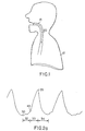
- Fig. 1 is a side sectional diagram of a patient having normal respiratory activity.
- Fig. 2a-c are graphs of normal respiratory waveforms (shown with full normal inspiration at the peak).
- Fig. 2a shows a respiratory effort waveform and indicated phases of the respiratory effort waveform.
- Fig. 2b shows a graph of a respiratory airflow waveform with Fig. 2c showing the corresponding respiratory effort waveform
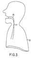
- Fig. 3 is a side sectional diagram of the patient of Fig. 1 at the onset of obstructive apnea.
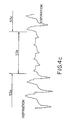
- Figs. 4a and 4b are respiratory waveforms of inspiratory effort showing normal inspiratory effort (Fig. 4a) and the change in normal inspiratory effort at the onset of an apnea event (Fig. 4b).
- Fig. 4c is a respiratory waveform showing respiratory airflow (as opposed to the respiratory effort waveform shown in Figs. 4a and 4b) in a patient during an apnea event.
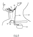
- Fig. 5 is an embodiment of the invention using an implanted pulse generator and implanted intrathoracic pressure sensor.
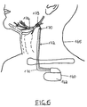
- Fig. 6 is an embodiment using an implanted pulse generator and implanted impedance sensor.
- Fig. 7 is a block diagram of one embodiment of the apnea treatment device according to the present invention.
- Fig. 8 is a block diagram of the upper airway transmitter/controller of Fig. 6 as it is applied to a patient.
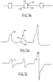
- Figs. 9a-c are waveforms showing the synchronization of stimulation from the upper airway transmitter of Fig. 7 (Fig. 9a) with the respiratory waveform from an implanted pressure sensor (Fig. 9b) and a corresponding intratracheal pressure waveform (Fig. 9c).
- the present invention relates to an apparatus for treatment of obstructive diseases of the upper airway by administering stimulation of the musculature of the upper airway in synchrony with the inspiratory phase of the respiratory cycle.
- Figs. 1 and 2a-c normal respiratory activity is depicted.
- a patient 10 has an airway 15 which remains patent during inspiration of air 20.
- Fig. 2a shows a typical respiratory effort waveform for two complete respiratory cycles. Each wave of the waveform.is characterized by a negative peak 30 on completion of expiration, a positive peak 35 on completion of inspiration and a turning point 40 which indicates the onset of inspiration.
- Each wave of the waveform can therefore be separated into a period of respiratory pause 32, an inspiratory phase 33 and an expiratory phase 34.
- Other characteristics of the waveform could also be identified in connection with tracking and analyzing the respiratory waveform to monitor respiratory activity in upper airway stimulation treatment.
- the respiratory effort waveform is related to airflow as set forth in Figs. 2b and 2c.
- Fig. 2b a trace of normal respiratory airflow from a flow transducer is shown while Fig. 2c shows the corresponding trace of the normal respiratory effort which produces the airflow.
- FIGs. 3 and 4b respiration in the same patient at the onset of an obstructive sleep apnea event is depicted.
- Fig. 3 shows the patient 10 and airway 15 with an airway obstruction 17 that is characteristic of an obstructive apnea event.
- Fig. 4a shows that in a normal respiratory effort waveform 43, the inspiratory peaks 45 a-d are of approximately the same amplitude.
- the inspiratory peaks 50 a-d become significantly greater in amplitude at the onset of obstructive apnea than the immediately preceding inspiratory peak 52. This is reflective of the increased inspiratory effort undertaken by the patient in response to the difficulty of breathing through the obstructed airway.
- the increased respiratory effort is avoided by synchronized stimulation of one or more muscles in the upper airway which hold the airway open during the inspiratory phase.
- the muscle or muscles stimulated can be selected from any number of muscles of the upper airway such as the genioglossus muscle which may be stimulated by a cuff electrode placed around the hypoglossal nerve.
- the effect of this stimulation on obstructive sleep apnea can be seen in the airflow trace of Fig. 4c.
- a first period indicated as 53a stimulation is enabled, thereby producing a normal respiratory airflow.
- a second period indicated as 53b stimulation is disabled causing obstruction of the airway and reduction in airflow volume (apnea).
- a third period indicated as 53c stimulation is resumed, restoring patency to the airway and increasing airflow volume.
- a device operating substantially as described above can be implemented in a fully implantable stimulation system such as that shown in Fig. 5.
- an implantable pulse generator 60 e.g. a Medtronic ITREL II Model 7424 modified to include an input from a respiratory sensor
- the Medtronic ITREL II implantable IPG has advanced programmable features permitting mode changes by transcutaneous RF telemetry.
- the patient-controllable parameters of the device's operation can therefore be controlled by the patient through a small, hand-held telemetry device while the physician can preset additional operational parameters of the device through an external programmer.
- the pressure sensor 70 is dynamic dp/dt type of pressure sensor such as that disclosed in U.S. Patent 4,407,296 to Anderson or U.S. Patent 4,485,813 issued to Anderson et al.
- the pressure sensor 70 is surgically implanted in a structure which has pressure coupling with the intrapleural space such as the suprasternal notch, the space between the trachea and esophagus, an intravascular placement or an intercostal placement.
- the suprasternal notch shown generally by numeral 75.
- the suprasternal notch is a well known structure on the upper chest just above the sternum that is anatomically coupled with the intrapleural space. Inspiration-synchronous stimulation is provided from the pulse generator 60 through a lead 72 to an electrode 73 around the hypoglossal nerve 74.
- an implantable pulse generator 160 e.g. a Medtronic ITREL II Model 7424 modified to include an input from a respiratory sensor
- the impedance measuring electrode 170 is a ring electrode disposed about a lead 172 terminating in a stimulation electrode 173. Therefore, the surgical implantation of the stimulation electrode 173 and lead 172 also provides the implantation of one measuring electrode 170 of the impedance measuring circuit and an associated conductor 171. Inspiration-synchronous stimulation is provided from the pulse generator 160 through the lead 172 to the nerve electrode 173 around the hypoglossal nerve 174.
- FIG. 7 A block diagram of the principal elements of the device is shown in Fig. 7. That device includes a controller 80 which is capable of sensing the inspiratory phase and transmitting an electrical stimulus pulse to muscles of the upper airway.
- a pressure sensor 85 sends respiratory waveform information to the controller 80 which sends stimulus pulses through an electrode 90 to stimulate the muscles of the patient.
- the electrode can be a Medtronic Model 3990 Half Cuff Nerve Electrode.
- a programmer 95 is capable of remote programming of controller 80 with various parameters in order to adapt the device to a particular patient.
- the device of Fig. 7 is therefore adapted to be programmed by the doctor and thereafter used each night by the patient to prevent the closure of the upper airway during the inspiratory phase of the respiration cycle.
- a programmer with basic on/off capabilities may also be provided to the patient in order to allow the patient to enable and disable the preprogrammed treatment. It will be apparent to those skilled in the art that the entire system must be made to be easy to use by the patient and since it is used without constant medical supervision, it must be able to safely adapt to many different operating conditions.
- Fig. 8 is a block diagram of the controller 80 of Fig. 7.
- a microprocessor 100 controls the principal operations of the controller 80.
- a pressure signal 89 from the pressure sensor 85 is coupled to an amplifier/filter 87 which filters artifacts from the signal 89 and an automatic gain control 88 so that it is compatible with analog or digital signal processing devices such as an analog/digital converter 91.
- the microprocessor 100 provides data to the D/A converter 101 and the oscillator 102 which allows the stimulus waveform to be shaped by the stimulus shaper 103 into an output signal 104.
- a telemetry system 105 is used with an external programmer (not shown) to communicate with the microprocessor.
- the pressure sensor 85 can be based on a piezoelectric crystal material which acts as a high impedance voltage source in response to deflections of a diaphragm to which it is rigidly attached. Additional electrical components can be included in the sensor; in the IPG and/or in the lead such that the necessary interfacing, signal recovery, and sensor excitation are accomplished.
- a piezoelectric crystal is a device producing a voltage proportional to the rate of mechanical deflection applied to a diaphragm membrane by a physiologic force. It therefore responds to changes in pressure, not to absolute pressure.
- a current is provided from the IPG to the lead system which produces an excitation of the sensor.
- a signal is then recovered from the sensor.
- the sensor is sampled at a predetermined time interval which produces a waveform corresponding to the mechanically applied physiological signal.
- intrathoracic pressure is negative during the inspiratory phase of respiration so that the sensor output is preferably inverted such that inspiration yields a positive-going voltage.
- the pulse generator biases the sensor at a current between about 8 ⁇ A and 80 ⁇ A depending on the output signal required. Since the piezoelectric element of the sensor will only respond to changes in pressure, constant pressure will result in the sensor output returning to a baseline value. Sensitivity of a pressure sensor of this type is about 3 mV/mmHg.
- the desired operational range for a pressure sensor is generally between about 1 cmH 2 O and 15 cmH 2 O (i.e.
- the IPG preferably includes an automatic gain/sensitivity control of conventional design to adapt to varying respiration levels and also to patient-to-patient pressure level variability.
- the microprocessor 100 identifies the inspiration phase of the respiratory effort waveform from the digitized amplitude values from the pressure sensor so that the system can supply a shaped stimulus burst for the duration of that phase at the electrode 90.
- the onset of inspiration is characterized as a sustained increase in slope of the pressure waveform greater than a preset threshold but less than a maximum slope value.
- an inspiratory turn point would be indicated by an increase in the pressure signal amplitude of between about 1.5X and 5X over two sample periods about 40 to 100 ms apart.
- the peak amplitude of the pressure signal indicates the end of inspiration and the onset of expiration.
- an inspiratory peak is detected if a negative slope for the pressure waveform is identified and sustained over three consecutive sample periods (i.e. over about 60 to 150 ms).
- an analog derivative of the respiration pressure signal can be used to determine onset and offset of inspiration.
- the pressure sensor output can be processed by the IPG to derive a time derivative of the fluid pressure applied to the pressure sensor.
- a baseline value for the signal is then established by averaging about 10 consecutive voltage measurements. If the average is above the previous baseline by a predetermined voltage, then the baseline is reset to the average value.
- a threshold voltage is established from the baseline voltage (e.g. baseline voltage minus a constant) that corresponds to the onset of inspiration. When the threshold voltage is achieved by the signal from the sensor, stimulation is enabled.
- the signal voltage may be averaged and then compared with the threshold voltage.
- Inspiratory offset may be found in a similar manner by computing a second threshold voltage (i.e. a negative voltage characteristic of the expiratory phase of the respiratory cycle) and identifying the point at which the second threshold is achieved.
- Figs. 9a-c indicate the basic mode of operation for the system.
- the patient's respiratory signal 110 derived from implanted pressure sensor is monitored and the inspiratory phase 112 of the signal 110 is identified from a waveform analysis which finds the turning point 113 and the inspiratory peak 114.
- This respiratory signal 110 can be seen to correspond closely with measured intratracheal pressure 111 in indicating the inspiratory phase of the respiratory cycle.
- the system then provides a stimulus burst to the appropriate upper airway musculature which is synchronized with the inspiratory phase 112.
- the shape of the stimulus burst is indicated as a stimulus window 115 which includes a peak amplitude 117 which is specifically set by the physician at a level required by the patient.
- a ramp gradually increasing the stimulus during a rise time and a ramp gradually decreasing the stimulus during a fall time may also be provided if desired.
- the stimulus would have a starting point 123 at the same time as the turning point 113 and continue to an end point 125 that is exactly at the inspiratory peak 114.
- the end point 125 for the stimulus window 115 may be delayed until the system clearly identifies the peak by seeing that the signal 110 is on a downward trend.
- the end point 125 may occur slightly after the inspiratory peak 114.
Claims (4)
- Dispositif médical pour traiter l'obstruction des voies aériennes supérieures chez un patient à l'aide d'une stimulation électrique des muscles des voies aériennes supérieures, comportant :caractérisé en ce que ledit capteur de pression (70) est un capteur dp/dt dynamique mesurant les changements de pression dans le temps et est adapté pour être implanté dans la fourchette supra-stemale, l'espace entre la trachée et l'oesophage, un emplacement intravasculaire ou un emplacement intercostal, de manière à avoir une pression se couplant avec l'espace intra-pleural, et comportant en outre des moyens (80) associés audit capteur de pression (70) pour surveiller le signal du capteur de pression implanté quant à un changement dans le temps dans la plage comprise entre 1,5X et 5X sur un intervalle compris entre 40 et 100 ms, ce changement étant indicatif du début d'une inspiration du patient, et des moyens (60) associés auxdits moyens de surveillance pour appliquer la stimulation électrique lors de la détection d'un début d'inspiration par les moyens de surveillance (80), la stimulation électrique étant appliquée à un niveau qui rétablit la perméabilité dans les voies aériennes.un capteur de pression implantable (70) adapté pour être chirurgicalement implanté à l'intérieur du patient, ledit capteur de pression délivrant un signal indicatif de changements de la pression intra-thoracique chez le patient dans le temps,
- Dispositif selon la revendication 1, comportant également des moyens d'établissement de seuil associés auxdits moyens de surveillance et auxdits moyens de stimulation pour établir une valeur de seuil pour le signal surveillé.
- Dispositif selon la revendication 2, dans lequel les moyens d'établissement de seuil comportent :(a) des moyens associés auxdits moyens de surveillance pour déterminer une valeur moyenne de ligne de base pour le signal surveillé,(b) des moyens associés auxdits moyens de détermination de ligne de base pour déterminer une valeur de seuil en fonction de la valeur moyenne de ligne de base.
- Dispositif selon l'une quelconque des revendications précédentes, comportant également des moyens associés auxdits moyens de surveillance pour numériser le signal surveillé.
Applications Claiming Priority (2)
| Application Number | Priority Date | Filing Date | Title |
|---|---|---|---|
| US310177 | 1994-09-21 | ||
| US08/310,177 US5540731A (en) | 1994-09-21 | 1994-09-21 | Method and apparatus for pressure detecting and treating obstructive airway disorders |
Publications (3)
| Publication Number | Publication Date |
|---|---|
| EP0702979A2 EP0702979A2 (fr) | 1996-03-27 |
| EP0702979A3 EP0702979A3 (fr) | 1997-03-19 |
| EP0702979B1 true EP0702979B1 (fr) | 2004-03-24 |
Family
ID=23201324
Family Applications (1)
| Application Number | Title | Priority Date | Filing Date |
|---|---|---|---|
| EP95306576A Expired - Lifetime EP0702979B1 (fr) | 1994-09-21 | 1995-09-18 | Dispositif de détection et traitement des maladies obstructives des voies aériennes |
Country Status (3)
| Country | Link |
|---|---|
| US (1) | US5540731A (fr) |
| EP (1) | EP0702979B1 (fr) |
| DE (1) | DE69532740T2 (fr) |
Families Citing this family (99)
| Publication number | Priority date | Publication date | Assignee | Title |
|---|---|---|---|---|
| US6021352A (en) * | 1996-06-26 | 2000-02-01 | Medtronic, Inc, | Diagnostic testing methods and apparatus for implantable therapy devices |
| US6132384A (en) * | 1996-06-26 | 2000-10-17 | Medtronic, Inc. | Sensor, method of sensor implant and system for treatment of respiratory disorders |
| US6093158A (en) * | 1997-05-15 | 2000-07-25 | Morris; Donald E. | Systems for modifying behavioral disorders |
| FR2780654B1 (fr) | 1998-07-06 | 2000-12-01 | Ela Medical Sa | Dispositif medical implantable actif permettant le traitement par electrostimulation du syndrome de l'apnee du sommeil |
| US6212435B1 (en) | 1998-11-13 | 2001-04-03 | Respironics, Inc. | Intraoral electromuscular stimulation device and method |
| US6450173B1 (en) | 1999-08-12 | 2002-09-17 | Obtech Medical Ag | Heartburn and reflux disease treatment with controlled wireless energy supply |
| US6482145B1 (en) | 2000-02-14 | 2002-11-19 | Obtech Medical Ag | Hydraulic anal incontinence treatment |
| US6471635B1 (en) | 2000-02-10 | 2002-10-29 | Obtech Medical Ag | Anal incontinence disease treatment with controlled wireless energy supply |
| US6464628B1 (en) | 1999-08-12 | 2002-10-15 | Obtech Medical Ag | Mechanical anal incontinence |
| AU769270B2 (en) * | 1999-08-12 | 2004-01-22 | Obtech Medical Ag | Stoma opening forming apparatus |
| US6758216B1 (en) * | 1999-09-15 | 2004-07-06 | Resmed Limited | Ventilatory assistance using an external effort sensor |
| EP1253877B1 (fr) | 2000-02-10 | 2005-05-11 | Potencia Medical AG | Appareil mecanique de traitement de l'impuissance |
| MXPA02007589A (es) | 2000-02-10 | 2004-08-23 | Potencia Medical Ag | Tratamiento controlado de incontinencia urinaria. |
| WO2001058388A1 (fr) | 2000-02-10 | 2001-08-16 | Potencia Medical Ag | Traitement d'incontinence d'urine a base d'energie radioelectrique |
| US7931582B2 (en) | 2000-02-11 | 2011-04-26 | Obtech Medical Ag | Controlled impotence treatment |
| EP1759665B1 (fr) | 2000-02-11 | 2014-10-22 | Urologica AG | Appareil de traitement de l'incontinence urinaire |
| US20030125768A1 (en) | 2000-02-11 | 2003-07-03 | Forsell Peter | Impotence treatment apparatus with energy transforming means |
| US20030100929A1 (en) * | 2000-02-14 | 2003-05-29 | Peter Forsell | Controlled penile prosthesis |
| WO2001047440A2 (fr) | 2000-02-14 | 2001-07-05 | Potencia Medical Ag | Appareil prothetique destine a lutter contre l'impuissance masculine pourvu d'une alimentation en energie sans fil |
| US7442165B2 (en) | 2000-02-14 | 2008-10-28 | Obtech Medical Ag | Penile prosthesis |
| US6357438B1 (en) * | 2000-10-19 | 2002-03-19 | Mallinckrodt Inc. | Implantable sensor for proportional assist ventilation |
| US6641542B2 (en) | 2001-04-30 | 2003-11-04 | Medtronic, Inc. | Method and apparatus to detect and treat sleep respiratory events |
| US20030195571A1 (en) * | 2002-04-12 | 2003-10-16 | Burnes John E. | Method and apparatus for the treatment of central sleep apnea using biventricular pacing |
| CA2493784C (fr) * | 2002-07-29 | 2016-04-26 | Potencia Medical Ag | Implant durable |
| US20040034275A1 (en) * | 2002-07-29 | 2004-02-19 | Peter Forsell | Multi-material incontinence treatment constriction device |
| JP2006507905A (ja) * | 2002-12-02 | 2006-03-09 | スコット・ラボラトリーズ・インコーポレイテッド | 呼吸監視システムおよび方法 |
| US7025730B2 (en) | 2003-01-10 | 2006-04-11 | Medtronic, Inc. | System and method for automatically monitoring and delivering therapy for sleep-related disordered breathing |
| US7277749B2 (en) * | 2003-01-15 | 2007-10-02 | Alfred E. Mann Institute For Biomedical Engineering At The University Of Southern California | Treatments for snoring using injectable neuromuscular stimulators |
| US20060149124A1 (en) * | 2003-01-31 | 2006-07-06 | Peter Forsell | Electrically operable impotence treatment apparatus |
| US20060142635A1 (en) * | 2003-01-31 | 2006-06-29 | Peter Forsell | Electrically operable incontinence treatment apparatus |
| US7155278B2 (en) * | 2003-04-21 | 2006-12-26 | Medtronic, Inc. | Neurostimulation to treat effects of sleep apnea |
| US20080161878A1 (en) * | 2003-10-15 | 2008-07-03 | Tehrani Amir J | Device and method to for independently stimulating hemidiaphragms |
| US7979128B2 (en) * | 2003-10-15 | 2011-07-12 | Rmx, Llc | Device and method for gradually controlling breathing |
| US8265759B2 (en) * | 2003-10-15 | 2012-09-11 | Rmx, Llc | Device and method for treating disorders of the cardiovascular system or heart |
| US8160711B2 (en) | 2003-10-15 | 2012-04-17 | Rmx, Llc | Multimode device and method for controlling breathing |
| US8140164B2 (en) * | 2003-10-15 | 2012-03-20 | Rmx, Llc | Therapeutic diaphragm stimulation device and method |
| US7970475B2 (en) | 2003-10-15 | 2011-06-28 | Rmx, Llc | Device and method for biasing lung volume |
| US9259573B2 (en) * | 2003-10-15 | 2016-02-16 | Rmx, Llc | Device and method for manipulating exhalation |
| US8467876B2 (en) * | 2003-10-15 | 2013-06-18 | Rmx, Llc | Breathing disorder detection and therapy delivery device and method |
| US8244358B2 (en) * | 2003-10-15 | 2012-08-14 | Rmx, Llc | Device and method for treating obstructive sleep apnea |
| US20050085874A1 (en) * | 2003-10-17 | 2005-04-21 | Ross Davis | Method and system for treating sleep apnea |
| US20050149132A1 (en) | 2003-12-24 | 2005-07-07 | Imad Libbus | Automatic baroreflex modulation based on cardiac activity |
| US7857369B2 (en) * | 2004-06-30 | 2010-12-28 | Case Western Reserve University | Biologically inspired gripping device |
| US7775966B2 (en) | 2005-02-24 | 2010-08-17 | Ethicon Endo-Surgery, Inc. | Non-invasive pressure measurement in a fluid adjustable restrictive device |
| US7775215B2 (en) | 2005-02-24 | 2010-08-17 | Ethicon Endo-Surgery, Inc. | System and method for determining implanted device positioning and obtaining pressure data |
| US7658196B2 (en) | 2005-02-24 | 2010-02-09 | Ethicon Endo-Surgery, Inc. | System and method for determining implanted device orientation |
| US8066629B2 (en) | 2005-02-24 | 2011-11-29 | Ethicon Endo-Surgery, Inc. | Apparatus for adjustment and sensing of gastric band pressure |
| US7927270B2 (en) | 2005-02-24 | 2011-04-19 | Ethicon Endo-Surgery, Inc. | External mechanical pressure sensor for gastric band pressure measurements |
| US7699770B2 (en) | 2005-02-24 | 2010-04-20 | Ethicon Endo-Surgery, Inc. | Device for non-invasive measurement of fluid pressure in an adjustable restriction device |
| US7909754B2 (en) * | 2005-02-24 | 2011-03-22 | Ethicon Endo-Surgery, Inc. | Non-invasive measurement of fluid pressure in an adjustable gastric band |
| US8016744B2 (en) | 2005-02-24 | 2011-09-13 | Ethicon Endo-Surgery, Inc. | External pressure-based gastric band adjustment system and method |
| US7636600B1 (en) * | 2005-10-21 | 2009-12-22 | Pacesetter, Inc. | Pressure monitoring for apnea prevention and/or therapy |
| US7519409B2 (en) * | 2005-12-29 | 2009-04-14 | Medtronic, Inc. | Implantable cell/tissue-based biosensing device |
| US7725195B2 (en) * | 2006-02-16 | 2010-05-25 | Imthera Medical, Inc. | RFID-based apparatus, system, and method for therapeutic treatment of obstructive sleep apnea |
| US8152710B2 (en) | 2006-04-06 | 2012-04-10 | Ethicon Endo-Surgery, Inc. | Physiological parameter analysis for an implantable restriction device and a data logger |
| US8870742B2 (en) | 2006-04-06 | 2014-10-28 | Ethicon Endo-Surgery, Inc. | GUI for an implantable restriction device and a data logger |
| US8688219B2 (en) | 2006-07-28 | 2014-04-01 | Medronic, Inc. | Dynamic sampling |
| AU2007313319B2 (en) | 2006-10-13 | 2012-03-22 | Cyberonics, Inc. | Obstructive sleep apnea treatment devices, systems and methods |
| US9913982B2 (en) | 2011-01-28 | 2018-03-13 | Cyberonics, Inc. | Obstructive sleep apnea treatment devices, systems and methods |
| US9744354B2 (en) | 2008-12-31 | 2017-08-29 | Cyberonics, Inc. | Obstructive sleep apnea treatment devices, systems and methods |
| US9205262B2 (en) | 2011-05-12 | 2015-12-08 | Cyberonics, Inc. | Devices and methods for sleep apnea treatment |
| US8855771B2 (en) | 2011-01-28 | 2014-10-07 | Cyberonics, Inc. | Screening devices and methods for obstructive sleep apnea therapy |
| US9186511B2 (en) | 2006-10-13 | 2015-11-17 | Cyberonics, Inc. | Obstructive sleep apnea treatment devices, systems and methods |
| US8280513B2 (en) * | 2006-12-22 | 2012-10-02 | Rmx, Llc | Device and method to treat flow limitations |
| CA2697822A1 (fr) * | 2007-10-09 | 2009-04-16 | Imthera Medical, Inc. | Appareil, systeme et procede de stimulation selective |
| WO2010042045A1 (fr) | 2008-10-10 | 2010-04-15 | Milux Holding S.A. | Système, appareil et procédé de traitement de patiente à dysfonctionnement sexuel |
| CA3187608A1 (fr) * | 2008-01-28 | 2009-08-06 | Implantica Patent Ltd. | Dispositif de drainage implantable |
| WO2009096857A1 (fr) | 2008-01-29 | 2009-08-06 | Milux Holding Sa | Dispositif, système et méthode de traitement de l'obésité |
| US20110152706A1 (en) * | 2008-05-15 | 2011-06-23 | Inspire Medical Systems, Inc. | Method and apparatus for sensing respiratory pressure in an implantable stimulation system |
| JP5547200B2 (ja) * | 2008-10-01 | 2014-07-09 | インスパイア・メディカル・システムズ・インコーポレイテッド | 睡眠時無呼吸を治療する経静脈法 |
| BRPI0920548B8 (pt) | 2008-10-09 | 2021-06-22 | Imthera Medical Inc | aparelho para controlar posição da língua de um paciente |
| CA3004121C (fr) | 2008-10-10 | 2020-06-16 | Medicaltree Patent Ltd. | Procede, systeme et dispositif d'assistance cardiaque |
| WO2010042058A1 (fr) | 2008-10-10 | 2010-04-15 | Milux Holding S.A. | Valvule artificielle perfectionnée |
| US8600510B2 (en) | 2008-10-10 | 2013-12-03 | Milux Holding Sa | Apparatus, system and operation method for the treatment of female sexual dysfunction |
| US8696745B2 (en) | 2008-10-10 | 2014-04-15 | Kirk Promotion Ltd. | Heart help device, system, and method |
| EP2349078A4 (fr) | 2008-10-10 | 2018-02-07 | Kirk Promotion LTD. | Moyen de fixation pour ensemble de surveillance médicale implantable |
| WO2010059839A2 (fr) | 2008-11-19 | 2010-05-27 | Inspire Medical Systems, Inc. | Procédé de traitement de troubles respiratoires du sommeil |
| AU2010201032B2 (en) * | 2009-04-29 | 2014-11-20 | Resmed Limited | Methods and Apparatus for Detecting and Treating Respiratory Insufficiency |
| US10952836B2 (en) | 2009-07-17 | 2021-03-23 | Peter Forsell | Vaginal operation method for the treatment of urinary incontinence in women |
| US9949812B2 (en) | 2009-07-17 | 2018-04-24 | Peter Forsell | Vaginal operation method for the treatment of anal incontinence in women |
| WO2011059531A1 (fr) | 2009-11-10 | 2011-05-19 | Imthera Medical, Inc. | Système de stimulation d'un nerf hypoglosse pour commande de la position de la langue d'un patient |
| JP6092212B2 (ja) | 2011-08-11 | 2017-03-08 | インスパイア・メディカル・システムズ・インコーポレイテッドInspire Medical Systems, Inc. | 呼吸努力の検知結果に基づいて刺激プロトコルを選択するためのシステム |
| US8983611B2 (en) | 2011-09-27 | 2015-03-17 | Cardiac Pacemakers, Inc. | Neural control of central sleep apnea |
| EP2809226B1 (fr) | 2012-01-31 | 2016-10-05 | Medtronic Inc. | Capteur comprenant canal de surverse |
| US9131858B2 (en) | 2012-01-31 | 2015-09-15 | Medtronic, Inc. | Sensor over-mold shape |
| US9517032B2 (en) | 2012-01-31 | 2016-12-13 | Medtronic, Inc. | Sensor over-mold shape |
| US9005134B2 (en) | 2012-01-31 | 2015-04-14 | Medtronic, Inc. | Sensor over-mold shape |
| EP3903727A1 (fr) | 2013-03-15 | 2021-11-03 | Implantica Patent Ltd. | Dispositif de limitation |
| US11383083B2 (en) | 2014-02-11 | 2022-07-12 | Livanova Usa, Inc. | Systems and methods of detecting and treating obstructive sleep apnea |
| WO2016033245A1 (fr) | 2014-08-26 | 2016-03-03 | Rmx, Llc | Dispositifs et procédés de réduction de la pression intrathoracique |
| JP6759227B2 (ja) | 2015-03-19 | 2020-09-23 | インスパイア・メディカル・システムズ・インコーポレイテッドInspire Medical Systems, Inc. | 閉塞性睡眠時無呼吸を治療する刺激 |
| US20170112390A1 (en) | 2015-10-22 | 2017-04-27 | Medtronic, Inc. | Atrial arrythmia detection using a pressure signal in an implantable medical device and medical system |
| WO2018089789A1 (fr) | 2016-11-10 | 2018-05-17 | The Research Foundation For The State University Of New York | Système, procédé et biomarqueurs d'obstruction des voies aériennes |
| AU2018215194B2 (en) | 2017-02-01 | 2023-02-02 | The Alfred E. Mann Foundation For Scientific Research | Stimulator systems and methods for obstructive sleep apnea |
| CN110755720B (zh) * | 2018-07-27 | 2022-06-14 | 欧姆龙健康医疗事业株式会社 | 呼吸检知方法和系统、气体提供方法和系统以及制氧机 |
| US11266838B1 (en) | 2019-06-21 | 2022-03-08 | Rmx, Llc | Airway diagnostics utilizing phrenic nerve stimulation device and method |
| WO2021195135A1 (fr) | 2020-03-23 | 2021-09-30 | The Alfred E. Mann Foundation For Scientific Research | Système pour traiter l'apnée obstructive du sommeil |
| US11931578B2 (en) | 2020-04-10 | 2024-03-19 | The Alfred E. Mann Foundation For Scientific Research | Acoustic sensing for respiration detection |
| WO2022099292A1 (fr) | 2020-11-04 | 2022-05-12 | The Alfred E. Mann Foundation For Scientific Research | Capteurs et méthodes de détermination de la respiration |
Citations (1)
| Publication number | Priority date | Publication date | Assignee | Title |
|---|---|---|---|---|
| US4830008A (en) * | 1987-04-24 | 1989-05-16 | Meer Jeffrey A | Method and system for treatment of sleep apnea |
Family Cites Families (21)
| Publication number | Priority date | Publication date | Assignee | Title |
|---|---|---|---|---|
| US4050458A (en) * | 1976-01-26 | 1977-09-27 | Puritan-Bennett Corporation | Respiration system with patient assist capability |
| US4180059A (en) * | 1978-02-03 | 1979-12-25 | City Of Hope National Medical Center | Method of measuring intrathoracic pressure |
| US4289142A (en) * | 1978-11-24 | 1981-09-15 | Kearns Kenneth L | Physiological occurrence, such as apnea, monitor and X-ray triggering device |
| US4407296A (en) * | 1980-09-12 | 1983-10-04 | Medtronic, Inc. | Integral hermetic impantable pressure transducer |
| US4485813A (en) * | 1981-11-19 | 1984-12-04 | Medtronic, Inc. | Implantable dynamic pressure transducer system |
| DE3483882D1 (de) * | 1984-02-07 | 1991-02-07 | Schiapparelli Medtronic S P A | Herzschrittmacher, abhaengig vom atmungsumfang pro zeiteinheit. |
| US5050614A (en) * | 1986-08-06 | 1991-09-24 | Spacelabs, Inc. | Apparatus and method for inspiration detection |
| US4784154A (en) * | 1986-11-13 | 1988-11-15 | Colin Electronics Co., Ltd. | Interference resistant biomedical transducer |
| US4960118A (en) * | 1989-05-01 | 1990-10-02 | Pennock Bernard E | Method and apparatus for measuring respiratory flow |
| JP2794196B2 (ja) * | 1989-06-20 | 1998-09-03 | チェスト株式会社 | 無呼吸防止刺激装置 |
| US5123425A (en) * | 1990-09-06 | 1992-06-23 | Edentec | Obstructive sleep apnea collar |
| US5211173A (en) * | 1991-01-09 | 1993-05-18 | Medtronic, Inc. | Servo muscle control |
| US5190053A (en) * | 1991-02-28 | 1993-03-02 | Jeffrey A. Meer, Revocable Living Trust | Method and apparatus for electrical sublingual stimulation |
| US5215082A (en) * | 1991-04-02 | 1993-06-01 | Medtronic, Inc. | Implantable apnea generator with ramp on generator |
| US5257636A (en) * | 1991-04-02 | 1993-11-02 | Steven J. White | Apparatus for determining position of an endothracheal tube |
| US5335657A (en) * | 1991-05-03 | 1994-08-09 | Cyberonics, Inc. | Therapeutic treatment of sleep disorder by nerve stimulation |
| US5174287A (en) * | 1991-05-28 | 1992-12-29 | Medtronic, Inc. | Airway feedback measurement system responsive to detected inspiration and obstructive apnea event |
| AU2339792A (en) * | 1991-07-22 | 1993-02-23 | Cyberonics, Inc. | Treatment of respiratory disorders by nerve stimulation |
| US5335666A (en) * | 1992-02-27 | 1994-08-09 | Edentec | Medical monitor with input regulation |
| US5271395A (en) * | 1992-04-17 | 1993-12-21 | Medtronic, Inc. | Method and apparatus for rate-responsive cardiac pacing |
| US5320643A (en) * | 1992-10-06 | 1994-06-14 | Medtronic, Inc. | Automatic cardiac capture restoration and threshold-seeking method and apparatus |
-
1994
- 1994-09-21 US US08/310,177 patent/US5540731A/en not_active Expired - Lifetime
-
1995
- 1995-09-18 DE DE69532740T patent/DE69532740T2/de not_active Expired - Lifetime
- 1995-09-18 EP EP95306576A patent/EP0702979B1/fr not_active Expired - Lifetime
Patent Citations (1)
| Publication number | Priority date | Publication date | Assignee | Title |
|---|---|---|---|---|
| US4830008A (en) * | 1987-04-24 | 1989-05-16 | Meer Jeffrey A | Method and system for treatment of sleep apnea |
Also Published As
| Publication number | Publication date |
|---|---|
| EP0702979A3 (fr) | 1997-03-19 |
| DE69532740D1 (de) | 2004-04-29 |
| DE69532740T2 (de) | 2005-04-28 |
| EP0702979A2 (fr) | 1996-03-27 |
| US5540731A (en) | 1996-07-30 |
Similar Documents
| Publication | Publication Date | Title |
|---|---|---|
| EP0702979B1 (fr) | Dispositif de détection et traitement des maladies obstructives des voies aériennes | |
| US5540732A (en) | Method and apparatus for impedance detecting and treating obstructive airway disorders | |
| US8688219B2 (en) | Dynamic sampling | |
| US5546952A (en) | Method and apparatus for detection of a respiratory waveform | |
| US5540733A (en) | Method and apparatus for detecting and treating obstructive sleep apnea | |
| US5522862A (en) | Method and apparatus for treating obstructive sleep apnea | |
| US5549655A (en) | Method and apparatus for synchronized treatment of obstructive sleep apnea | |
| US5483969A (en) | Method and apparatus for providing a respiratory effort waveform for the treatment of obstructive sleep apnea | |
| US6572543B1 (en) | Sensor, method of sensor implant and system for treatment of respiratory disorders | |
| US5485851A (en) | Method and apparatus for arousal detection | |
| EP0914179B1 (fr) | Commande de gain pour un signal periodique | |
| US5944680A (en) | Respiratory effort detection method and apparatus | |
| US6099479A (en) | Method and apparatus for operating therapy system | |
| US6021352A (en) | Diagnostic testing methods and apparatus for implantable therapy devices | |
| EP0940155B1 (fr) | Appareil pour le traitement de l'apnée pendant le sommeil | |
| JPH09215757A (ja) | 上部気道障害を処理するための医療用装置 | |
| AU768822B2 (en) | Method and apparatus for operating therapy system | |
| AU1830801A (en) | System for treatment of respiratory disorders |
Legal Events
| Date | Code | Title | Description |
|---|---|---|---|
| PUAI | Public reference made under article 153(3) epc to a published international application that has entered the european phase |
Free format text: ORIGINAL CODE: 0009012 |
|
| AK | Designated contracting states |
Kind code of ref document: A2 Designated state(s): DE FR IT NL SE |
|
| PUAL | Search report despatched |
Free format text: ORIGINAL CODE: 0009013 |
|
| AK | Designated contracting states |
Kind code of ref document: A3 Designated state(s): DE FR IT NL SE |
|
| 17P | Request for examination filed |
Effective date: 19970507 |
|
| 17Q | First examination report despatched |
Effective date: 20000921 |
|
| GRAP | Despatch of communication of intention to grant a patent |
Free format text: ORIGINAL CODE: EPIDOSNIGR1 |
|
| GRAS | Grant fee paid |
Free format text: ORIGINAL CODE: EPIDOSNIGR3 |
|
| GRAA | (expected) grant |
Free format text: ORIGINAL CODE: 0009210 |
|
| AK | Designated contracting states |
Kind code of ref document: B1 Designated state(s): DE FR IT NL SE |
|
| PG25 | Lapsed in a contracting state [announced via postgrant information from national office to epo] |
Ref country code: NL Free format text: LAPSE BECAUSE OF FAILURE TO SUBMIT A TRANSLATION OF THE DESCRIPTION OR TO PAY THE FEE WITHIN THE PRESCRIBED TIME-LIMIT Effective date: 20040324 Ref country code: IT Free format text: LAPSE BECAUSE OF FAILURE TO SUBMIT A TRANSLATION OF THE DESCRIPTION OR TO PAY THE FEE WITHIN THE PRE;WARNING: LAPSES OF ITALIAN PATENTS WITH EFFECTIVE DATE BEFORE 2007 MAY HAVE OCCURRED AT ANY TIME BEFORE 2007. THE CORRECT EFFECTIVE DATE MAY BE DIFFERENT FROM THE ONE RECORDED.SCRIBED TIME-LIMIT Effective date: 20040324 |
|
| REF | Corresponds to: |
Ref document number: 69532740 Country of ref document: DE Date of ref document: 20040429 Kind code of ref document: P |
|
| PG25 | Lapsed in a contracting state [announced via postgrant information from national office to epo] |
Ref country code: SE Free format text: LAPSE BECAUSE OF FAILURE TO SUBMIT A TRANSLATION OF THE DESCRIPTION OR TO PAY THE FEE WITHIN THE PRESCRIBED TIME-LIMIT Effective date: 20040624 |
|
| RAP2 | Party data changed (patent owner data changed or rights of a patent transferred) |
Owner name: MEDTRONIC, INC. |
|
| NLV1 | Nl: lapsed or annulled due to failure to fulfill the requirements of art. 29p and 29m of the patents act | ||
| ET | Fr: translation filed | ||
| PLBE | No opposition filed within time limit |
Free format text: ORIGINAL CODE: 0009261 |
|
| STAA | Information on the status of an ep patent application or granted ep patent |
Free format text: STATUS: NO OPPOSITION FILED WITHIN TIME LIMIT |
|
| 26N | No opposition filed |
Effective date: 20041228 |
|
| REG | Reference to a national code |
Ref country code: FR Ref legal event code: TP Owner name: INSPIRE MEDICAL SYSTEMS, INC., US Effective date: 20110829 |
|
| PGFP | Annual fee paid to national office [announced via postgrant information from national office to epo] |
Ref country code: DE Payment date: 20140911 Year of fee payment: 20 |
|
| PGFP | Annual fee paid to national office [announced via postgrant information from national office to epo] |
Ref country code: FR Payment date: 20140906 Year of fee payment: 20 |
|
| REG | Reference to a national code |
Ref country code: DE Ref legal event code: R071 Ref document number: 69532740 Country of ref document: DE |