EP0702803B1 - Hinge system for eyewear - Google Patents
Hinge system for eyewear Download PDFInfo
- Publication number
- EP0702803B1 EP0702803B1 EP94920053A EP94920053A EP0702803B1 EP 0702803 B1 EP0702803 B1 EP 0702803B1 EP 94920053 A EP94920053 A EP 94920053A EP 94920053 A EP94920053 A EP 94920053A EP 0702803 B1 EP0702803 B1 EP 0702803B1
- Authority
- EP
- European Patent Office
- Prior art keywords
- front frame
- post
- fingers
- temple
- temples
- Prior art date
- Legal status (The legal status is an assumption and is not a legal conclusion. Google has not performed a legal analysis and makes no representation as to the accuracy of the status listed.)
- Expired - Lifetime
Links
Images

Classifications
-
- G—PHYSICS
- G02—OPTICS
- G02C—SPECTACLES; SUNGLASSES OR GOGGLES INSOFAR AS THEY HAVE THE SAME FEATURES AS SPECTACLES; CONTACT LENSES
- G02C5/00—Constructions of non-optical parts
- G02C5/22—Hinges
- G02C5/2209—Pivot bearings and hinge bolts other than screws
-
- G—PHYSICS
- G02—OPTICS
- G02C—SPECTACLES; SUNGLASSES OR GOGGLES INSOFAR AS THEY HAVE THE SAME FEATURES AS SPECTACLES; CONTACT LENSES
- G02C2200/00—Generic mechanical aspects applicable to one or more of the groups G02C1/00 - G02C5/00 and G02C9/00 - G02C13/00 and their subgroups
- G02C2200/08—Modular frames, easily exchangeable frame parts and lenses
-
- G—PHYSICS
- G02—OPTICS
- G02C—SPECTACLES; SUNGLASSES OR GOGGLES INSOFAR AS THEY HAVE THE SAME FEATURES AS SPECTACLES; CONTACT LENSES
- G02C2200/00—Generic mechanical aspects applicable to one or more of the groups G02C1/00 - G02C5/00 and G02C9/00 - G02C13/00 and their subgroups
- G02C2200/20—Friction elements
Definitions
- the present invention relates to an eyewear frame and more particularly, relates to an eyewear frame with a hinge system which permits easy interchange or replacement of temples.
- Eyewear such as sunglasses or spectacles, typically comprise a front frame for holding at least one lens, temples which extend out and over the ear of the wearer, and hinges for attaching the temples to the front frame.
- the front frames comprise a pair of rims each holding a lens and attached by a bridge and/or brace. More recently, the front frames comprise a top member which holds a single unitary lens.
- Hinges typically consist of two interlocking pieces, one attached to the front frame through either a rim or a top member, and the other attached to the temple, also referred to as an ear stem. The interlocking pieces are connected by a tongue and groove relationship and held together using conventional fasteners such as screws.
- interchangeable eyewear components are now available so that the wearer may change the eyewear to meet their needs based on level of activity and environmental conditions. More specifically, lenses can be interchanged to better compensate for varying light conditions such as early morning, mid-day, and late evening sunlight.
- Temples have also been designed which are interchangeable to meet the wearer's requirements.
- One such temple can be a conventional paddle temple which is comfortable during leisure, but will not securely hold the eyewear on the wearer's head during active movement.
- a second such temple can be a cable temple which provides the secure attachment needed when engaged in rapid movement or activities, but which can sometimes be uncomfortable.
- interchangeable eyewear components have also been developed for aesthetic purposes allowing the wearer to change colours or styles of the components as desired.
- US-A-2,671,379 discloses an eyewear frame comprising a front frame, a hinge system at each of the opposite ends of the front frame and a temple releasably attached to each hinge system so as to be pivotable between a fully extended position approximately perpendicular to the front frame and a fully folded position approximately parallel to the front frame.
- each hinge system provides a post which extends vertically with respect to the front frame and each temple has a receiving member attached to its front end, the receiving member comprising two arcuately shaped fingers which are arranged perpendicularly to the post.
- a first portion of each of these fingers defines a segment of a circle forming a recess, and the fingers frictionally and pivotally engage the post along the inner periphery of these recesses.
- each hinge system comprises a generally "T"-shaped member formed from the post and a connecting element which extends horizontally with respect to the front frame to attach the post to the frame, the "T"-shaped member defining first and second vertically spaced openings between a portion of the front frame and the side of the post facing the end of the front frame opposite to which the post is attached, in that the arcuately shaped fingers of each temple extend through the first and second openings respectively with the post being located in the recess, and in that the fingers each comprise a respective second portion extending from the first portion, wherein the second portion has an outer periphery shaped such as to abut the portion of the front frame immediately adjacent the corresponding opening when the temples are in their fully extended positions, the fingers thereby acting as a positive stop to prevent further pivotal movement of said temples in a direction away from the front frame when the temples are moved to their
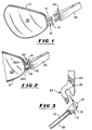
- hinge system of the eyewear frame of the present invention comprises two members, a hinge member 12 which is attached to the front frame 10 and a receiving member 22 which is attached to a temple 20.
- the hinge member 12 comprises a generally "T"-shaped member which extends sidewardly from the front frame 10. More specifically, hinge member 12 has connecting element 13 for holding post 14.
- Front frame 10 can be a rim for holding at least one lens, as shown.
- front frame 10 can comprise a conventional dual rim frame having separate means for holding the lens together such as a bridge and/or a brace (not shown), as is well known to those skilled in the art.
- front frame 10 can be a top frame member or a brow member with separate means for holding at least one lens (not shown).
- This second embodiment can be a top frame member such as is common in sports sunglasses having a unitary lens attached to the top frame.
- generally "T"-shaped hinge member 12 extends outwardly from front frame 10 so that post 14 is vertical with respect to front frame 10 when in the normal wearing position.
- Hinge member 12 can be made of either a suitable metal or plastic but is preferably made of the same material as front frame 10.
- front frame 10 is made from a metal wire typically used in eyewear frames, such as steel, nickel, titanium, copper and alloys thereof, hinge member 12 will be made of the same metal.
- Front frame 10 can also be made of a mouldable plastic, such as polyamides; polycarbonates; celluloses such as acetates, butyrates and proprionates and similar polymers or copolymers.
- Hinge member 12 will, preferably, be made from the same plastic as the front frame 10.
- hinge member 12 can be made of a different material from that of front frame 10 and affixed to front frame 10 by brazing, soldering, the use of fasteners, adhesives, or any other suitable means for attaching the two materials.
- the receiving member 22 comprises means for frictionally receiving post 14 and is attached to temple 20.
- Temple 20 can be a conventional temple having a substantially flat ear piece curved downwardly beginning at a point near its contact point with the ear.
- temple 20 can be a cable temple made of any flexible material to wrap around the back of the ear as is well known.
- Other shapes and configurations for temple member 20 can be employed.
- Receiving member 22 has a generally arcuate shaped element defining a recess 23 for frictionally receiving post 14 of hinge member 12 through a suitable recess area. Post 14 fits into recess 23 which acts as a seat allowing post 14 to pivot.
- the receiving member 22 has two curved fingers, 22a and 22b, which project substantially tangentially from one side of the arcuately shaped element and which straddle connecting member 13 when post 14 is within recess 23 as shown in Fig. 4. Curved fingers 22a and 22b also restrict the outward movement of temple 20 through contact with front frame 10 and will function as a positive stop. In this manner, temple 20 will remain substantially perpendicular to front frame 10 when the temple 20 is in the open position for placement on the wearer's head.
- Receiving member 22 can have other configurations which provide for a recess which can accept or mate with post 14.
- post 14 and recess 23 within receiving member 22 have substantially complementary shapes to form a frictional snap interfit.
- post 14 is cylindrical and recess 23 defines a circle to receive cylindrical post 14.
- receiving member 22 can be made of any suitable metal or plastic but is preferably made of the same material as temple 20 and is most preferably integral therewith. However, receiving member 22 can be made from a different material than temple 20 and be affixed to temple 20 by any suitable means as described above. Suitable materials for receiving member 22 include metal wires described above and mouldable plastics as described above.
- the present invention provides a hinge system which can be used to interchangeably remove and replace the front frame 10 and the temples 20.
- the front frame containing or comprising at least one lens and preferably two lenses, will have a temple extending sidewardly on opposite ends.
- the wearer can simply snap a temple 20 containing receiving member 22 on or off of the front frame 10 at their option. In this manner, temples can be forcibly removed and replaced for aesthetic or functional purposes.
- the front frame containing or comprising the lens(es) can also be replaced allowing the use of the same temples.
- the front frame and temples which employ the hinge system of the present invention are separated during accidental impact, avoiding breakage or injury.
- receiving member 22 can be made of any suitable metal or plastic but is preferably made of the same material as temple 20 and is most preferably integral therewith. However, receiving member 22 can be made from a different material than temple 20 and be affixed to temple 20 by any suitable means as described above. Suitable materials for receiving member 22 include metal wires described above and moldable plastics as described above.
- the present invention provides a hinge system which can be used to interchangeably remove and replace the front frame 10 and the temples 20.
- the front frame containing or comprising at least one lens and preferably two lenses, will have a temple extending sidewardly on opposite ends.
- the wearer can simple snap a temple 20 containing receiving member 22 on or off of the front frame 10 at their option. In this manner, temples can be forcibly removed and replaced for aesthetic or functional purposes.
- the front frame containing or comprising the lens(es) can also be replaced allowing the use of the same temples.
- the front frame and temples which employ the hinge system of the present invention are separated during accidental impact, avoiding breakage or injury.
Abstract
Description
Claims (4)
- An eyewear frame comprising a front frame (10), a hinge system (12) at each of the opposite ends of said front frame and a temple (20) releasably attached to each said hinge system so as to be pivotable between a fully extended position approximately perpendicular to said front frame (10) and a fully folded position approximately parallel to said front frame, each said hinge system providing a post (14) which extends vertically with respect to said front frame, and each said temple (20) having a receiving member (22) attached to its front end, the receiving member comprising two arcuately shaped fingers (22a,22b) which are arranged perpendicularly to said post (14), a first portion of each of said fingers (22a,22b) defining a segment of a circle forming a recess (23), and said fingers (22a,22b) frictionally and pivotally engaging said post (14) along the inner periphery of said recesses (23),
characterized in that:each said hinge system (12) comprises a generally "T"-shaped member formed from said post (14) and a connecting element (13) which extends horizontally with respect to said front frame (10) to attach said post (14) to said front frame (10), said "T"-shaped member defining first and second vertically spaced openings between a portion of said front frame (10) and the side of said post (14) facing the end of said front frame (10) opposite to which said post (14) is attached,in thatsaid arcuately shaped fingers (22a,22b) of each said temple (20) extend through said first and second openings respectively with said post (14) being located in said recess (23), and in that said fingers (22a, 22b) each comprise a respective second portion extending from said first portion, wherein said second portion has an outer periphery shaped such as to abut the portion of said front frame (10) immediately adjacent the corresponding opening when said temples (20) are in their fully extended positions, said fingers (22a,22b) thereby acting as a positive stop to prevent further pivotal movement of said temples (20) in a direction away from said front frame (10) when said temples (20) are moved to their fully extended positions. - An eyewear frame according to Claim 1, wherein said second portion of each said finger (22a,22b) is located on that side of said recess (23) which is opposite the attached said one end of said temple (20).
- An eyewear frame according to Claim 1 or Claim 2, wherein said recess (23) of each said finger (22a,22b) and said posts (14) are complementarily shaped so as to provide a releasable snap-type engagement between said fingers (22a,22b) and said posts (14).
- An eyewear frame according to any preceding claim, wherein said fingers (22a,22b) extend in a direction away and sidewardly of said front frame (10) when said temples (20) are in their fully folded position.
Applications Claiming Priority (3)
| Application Number | Priority Date | Filing Date | Title |
|---|---|---|---|
| US73233 | 1993-06-07 | ||
| US08/073,233 US5418581A (en) | 1993-06-07 | 1993-06-07 | Hinge system for eyewear |
| PCT/US1994/006115 WO1994029763A1 (en) | 1993-06-07 | 1994-05-31 | Hinge system for eyewear |
Publications (2)
| Publication Number | Publication Date |
|---|---|
| EP0702803A1 EP0702803A1 (en) | 1996-03-27 |
| EP0702803B1 true EP0702803B1 (en) | 1998-03-18 |
Family
ID=22112550
Family Applications (1)
| Application Number | Title | Priority Date | Filing Date |
|---|---|---|---|
| EP94920053A Expired - Lifetime EP0702803B1 (en) | 1993-06-07 | 1994-05-31 | Hinge system for eyewear |
Country Status (9)
| Country | Link |
|---|---|
| US (1) | US5418581A (en) |
| EP (1) | EP0702803B1 (en) |
| CN (1) | CN1038878C (en) |
| AU (1) | AU681414B2 (en) |
| BR (1) | BR9407116A (en) |
| DE (1) | DE69409108T2 (en) |
| ES (1) | ES2115955T3 (en) |
| HK (1) | HK1010063A1 (en) |
| WO (1) | WO1994029763A1 (en) |
Families Citing this family (67)
| Publication number | Priority date | Publication date | Assignee | Title |
|---|---|---|---|---|
| JP2527243Y2 (en) * | 1993-09-21 | 1997-02-26 | 株式会社ナカニシオプティカル | Eyeglass Temple Joint Structure |
| IT1266093B1 (en) * | 1993-12-03 | 1996-12-20 | Killer Loop Spa | HINGE STRUCTURE FOR GLASSES |
| IT1275030B (en) * | 1994-06-27 | 1997-07-29 | Killer Loop Spa | INTERCONNECTION AND LOCKING DEVICE OF TWO GLASSES OR PROTECTIVE ELEMENTS FOR SPORT |
| IT1279475B1 (en) * | 1995-11-22 | 1997-12-10 | Killer Loop Spa | HINGE STRUCTURE, ESPECIALLY FOR PLASTIC GLASSES |
| WO1997021135A1 (en) * | 1995-12-05 | 1997-06-12 | The Beta Group | Hinge connection for eyeglass frame |
| US5652637A (en) * | 1996-03-11 | 1997-07-29 | Marini; Martin A. | Eyeglasses with detachable temples |
| US6149268A (en) * | 1996-05-02 | 2000-11-21 | Cabot Safety Intermediate Corporation | Protective eyewear with at least one ventilation channel |
| US6276795B1 (en) | 1996-05-02 | 2001-08-21 | Aearo Company | Protective eyewear with adjustable strap |
| US6024446A (en) | 1996-05-02 | 2000-02-15 | Cabot Safety Intermediate Corporation | Eyewear with hingedly attached strapped head retainer |
| US5909267A (en) * | 1996-05-02 | 1999-06-01 | Cabot Safety Intermediate Corporation | Pantascopic adjustment mechanism for eyewear |
| US5818568A (en) * | 1997-05-07 | 1998-10-06 | Eye-Protor Kobayashi Inc. | Eyeglass frame assembly having screw-less hinges |
| DE19721306C2 (en) * | 1997-05-21 | 2002-06-20 | Hemaris Gmbh Chur | Joint for glasses |
| US6116733A (en) * | 1997-06-05 | 2000-09-12 | The Beta Group | Hinge connection for a temple piece of an eyeglass frame |
| DK176749B1 (en) | 1997-10-16 | 2009-06-08 | Lindberg As | Glasses frame, glasses and method of making a glasses frame |
| US5917575A (en) * | 1998-04-21 | 1999-06-29 | Cunningham; Alan | Split rim eyeglass frame mounting |
| US6231181B1 (en) | 2000-03-23 | 2001-05-15 | Qr Spex, Inc. | Exchangeable eyeglass temple pieces utilizing quick-connect attachment |
| DE60007119D1 (en) * | 2000-07-31 | 2004-01-22 | M M Evolution S R L | eyeglass frame |
| ATE241158T1 (en) | 2000-12-21 | 2003-06-15 | F A Thiele As | GLASSES FRAME AND ASSOCIATED HINGE ARRANGEMENT |
| CA2337940C (en) * | 2001-02-23 | 2007-09-25 | Leader Industries Inc. | Eyewear |
| US6994434B2 (en) * | 2001-02-23 | 2006-02-07 | Cabot Safety Intermediate Corp. | Eyewear with lens hinge |
| US6575570B2 (en) | 2001-10-05 | 2003-06-10 | M.M. Evolution S.R.L. | Spectacle frame |
| US6582075B1 (en) | 2001-10-18 | 2003-06-24 | Qr Spex, Inc. | Eyeglass temple attachment mechanism |
| US7029115B2 (en) * | 2004-03-19 | 2006-04-18 | Michael Toulch | Rimless eyeglasses |
| ITPD20040033U1 (en) * | 2004-04-09 | 2004-07-09 | Allison S P A | HINGE STRUCTURE FOR GLASSES |
| DE202004020521U1 (en) * | 2004-05-13 | 2005-09-15 | Bradtke Ulla | Spectacle frame has a centre section with lens frame and pivoting side arms with spring tab |
| DE102004027012A1 (en) * | 2004-05-28 | 2005-12-22 | Mykita Gmbh | Brillengestell |
| US7101039B2 (en) * | 2004-06-24 | 2006-09-05 | Maling Chris E | Durable eyeglasses frame assembly |
| US20060139567A1 (en) * | 2004-09-20 | 2006-06-29 | Michael Toulch | Eyeglasses with detachable bows |
| DE102005020891B4 (en) * | 2005-05-04 | 2007-11-29 | Ccs Royal Brillenmode Gmbh | glasses hinge |
| FR2891923B1 (en) * | 2005-10-11 | 2007-12-21 | Oxibis Exalto Soc Par Actions | GLASSES OF THE INTERCHANGEABLE BRANCH TYPE. |
| US7121663B1 (en) * | 2006-04-19 | 2006-10-17 | Paul Chen | Eyeglasses assembly |
| FR2923621B1 (en) * | 2007-11-14 | 2010-06-11 | Oxibis Exalto Sas | GLASSES OF THE TYPE WITH ARTICULATIONS WITHOUT SCREWS |
| CN101320141B (en) * | 2008-07-19 | 2010-06-09 | 江迪武 | Special hinge for injection-molded spectacle frame |
| FR2940473B1 (en) * | 2008-12-24 | 2011-08-05 | Laurent Linossier | HINGE FOR EYEWEAR MOUNTS |
| US20110273661A1 (en) * | 2009-08-10 | 2011-11-10 | High Rainbow Ent. Co., Ltd. | Eyeglasses |
| US20120050663A1 (en) | 2010-08-27 | 2012-03-01 | Suzanne Huston | Eyeglasses with interchangeable temple pieces |
| NZ589698A (en) | 2010-12-03 | 2013-07-26 | Francis William Austin | Eyeglass Hinge Assembly which allows removal of the arms |
| KR101124296B1 (en) * | 2011-05-31 | 2012-03-27 | 김장락 | Glasses having attachable and detachable leg frame using magnets |
| JP5934798B2 (en) | 2011-09-22 | 2016-06-15 | オークリー インコーポレイテッド | Mounting mechanism for eyewear |
| US8573772B2 (en) * | 2011-11-18 | 2013-11-05 | Yung-An Chen | Eyeglasses |
| US9122078B2 (en) * | 2011-12-01 | 2015-09-01 | Oakley, Inc. | Releasable earstem mounting mechanism for eyewear |
| TW201333578A (en) * | 2012-02-10 | 2013-08-16 | Jiann Lih Optical Co Ltd | Eyeglass temple structure |
| US9241833B2 (en) | 2012-08-31 | 2016-01-26 | Oakley, Inc. | Eyewear having multiple ventilation states |
| US8832904B2 (en) | 2012-09-04 | 2014-09-16 | Armand Kidouchim | Eye wear hinge and process for assembly |
| US9638934B2 (en) | 2012-09-04 | 2017-05-02 | Armand Kidouchim | Eyewear hinge and process for assembly |
| ITPD20120358A1 (en) * | 2012-11-30 | 2014-05-31 | Silcon Plastic Srl | PERFECTED HINGE FOR GLASSES |
| US20140321910A1 (en) * | 2013-04-26 | 2014-10-30 | Tait Towers Manufacturing, LLC | Pinned structure |
| ITRM20130622A1 (en) * | 2013-11-11 | 2015-05-12 | Fabio Nicola Arrizza | EYEWEAR AND RELATED FRAME |
| FR3013464A1 (en) * | 2013-11-18 | 2015-05-22 | Cfdg | ARTICULATED ASSEMBLY OF TWO PIECES |
| CA2943798C (en) | 2014-03-27 | 2019-08-20 | Oakley, Inc. | Mounting mechanism for eyewear |
| US9964779B2 (en) * | 2014-04-25 | 2018-05-08 | Monique Poole | Interchangeable glasses system |
| US10261338B2 (en) | 2015-01-15 | 2019-04-16 | Addo Industries, Llc | Eyewear comprising suspension system for nose and ears |
| CN106405864A (en) * | 2015-08-13 | 2017-02-15 | 天津永兴泰科技有限公司 | Sunglasses with adjustable width between legs |
| WO2017062813A1 (en) | 2015-10-09 | 2017-04-13 | Oakley, Inc. | Headworn supports with passive venting and removable lens |
| US9709817B2 (en) | 2015-12-07 | 2017-07-18 | Oakley, Inc. | Eyewear retention devices and methods |
| US10156734B2 (en) | 2015-12-08 | 2018-12-18 | Oakley, Inc. | Eyewear traction devices and methods |
| FR3047323B1 (en) * | 2016-01-29 | 2018-04-06 | Oxibis Group | SPECTACLE FRAME |
| AT518214B1 (en) * | 2016-02-04 | 2017-12-15 | Strom Eyewear Gmbh | Hinge joint for a pair of glasses |
| US10359642B2 (en) | 2016-04-22 | 2019-07-23 | Oakley, Inc. | Mounting mechanism for eyewear |
| US10061140B2 (en) | 2017-02-02 | 2018-08-28 | Francesco Ferretti | Eyeglass frames with detachable temple pieces |
| US10451882B2 (en) | 2018-03-16 | 2019-10-22 | Sharp Kabushiki Kaisha | Hinged lens configuration for a compact portable head-mounted display system |
| CN110333608A (en) * | 2019-07-05 | 2019-10-15 | 广州高增科技有限公司 | A kind of hinge for spectacles using large semicircle hinge pore structure |
| US10690937B1 (en) * | 2019-10-17 | 2020-06-23 | Banjohtos, LLC | Modular spectacles with multi-piece hinge |
| FR3106219B1 (en) * | 2020-01-14 | 2023-11-03 | Innotech Inc | Plastic hinge |
| TWI714468B (en) * | 2020-03-04 | 2020-12-21 | 雅德視國際股份有限公司 | Glasses with ventilative structure |
| US11747647B2 (en) * | 2020-05-18 | 2023-09-05 | Edward Chay | Endpiece assemblies for eyeglasses |
| IT202100019931A1 (en) * | 2021-07-27 | 2023-01-27 | Sartoria Rambaldi S R L | TEMPLE AND FRONT OF GLASSES FRAME, METHOD OF PRODUCTION OF THE TEMPLE AND/OR FRONT AND METHOD OF ASSEMBLY OF SUCH GLASSES FRAME |
Family Cites Families (21)
| Publication number | Priority date | Publication date | Assignee | Title |
|---|---|---|---|---|
| US2210507A (en) * | 1938-02-21 | 1940-08-06 | Spill Mfg Co Inc | Eyeglasses |
| US2379928A (en) * | 1942-11-10 | 1945-07-10 | Lapin Products Inc | Spectacles |
| US2504157A (en) * | 1943-09-23 | 1950-04-18 | Lapin Products Inc | Molded plastic sunglasses and the like |
| GB576400A (en) * | 1943-09-23 | 1946-04-02 | Lapin Products Inc | Improvement in spectacles |
| GB588225A (en) * | 1945-02-07 | 1947-05-16 | Norman Victor Lundie | Improvements in or relating to spectacles |
| GB608059A (en) * | 1946-02-14 | 1948-09-09 | Dufay Chromex Ltd | Improvements in and relating to sun spectacles |
| US2671379A (en) * | 1950-08-23 | 1954-03-09 | Polaroid Corp | Ophthalmic mounting |
| GB734208A (en) * | 1952-11-25 | 1955-07-27 | Albert Alexander Irons | Improvements in or relating to spectacle frames |
| GB884244A (en) * | 1960-07-14 | 1961-12-13 | Trabon Engineering Corp | Improvements relating to lubricating systems |
| US3394980A (en) * | 1964-06-11 | 1968-07-30 | Safemaster Inc | Spectacles with adjustable length temples |
| US3744887A (en) * | 1972-06-22 | 1973-07-10 | Esb Inc | Plastic hinge for spectacles |
| US4017165A (en) * | 1975-09-22 | 1977-04-12 | Frank S. Griffin | Eyeglass frames |
| US4153347A (en) * | 1977-06-08 | 1979-05-08 | Myer C Randolph | Eyeglass frames with removable, interchangeable lenses, rims and temple pieces |
| DE3404511A1 (en) * | 1984-02-09 | 1985-08-14 | Helmut 7530 Pforzheim Wünsch | Hinge for a spectacle bow |
| US4730915A (en) * | 1985-01-11 | 1988-03-15 | Oakley, Inc. | Detachable component sunglasses |
| US4824233A (en) * | 1985-01-11 | 1989-04-25 | Jannard James H | Multi-component sunglasses |
| IT8553881V0 (en) * | 1985-10-02 | 1985-10-02 | Lorenzo Poz Mario D I De | HINGE FOR GLASSES FRAMES |
| US4670915A (en) * | 1986-03-17 | 1987-06-09 | Evans Bradley J | Interchangeable eyeshield |
| IT1223738B (en) * | 1988-07-29 | 1990-09-29 | Fulvio Brucato | GLASSES |
| AT397441B (en) * | 1991-01-17 | 1994-04-25 | Silhouette Int Gmbh | HINGE JOINT BETWEEN BRACKETS AND BRACKET JAWS OF A GLASSES FRAME |
| IT1253556B (en) * | 1991-12-05 | 1995-08-08 | SIMPLIFIED ELASTICIZATION HINGE, PARTICULARLY FOR GLASSES |
-
1993
- 1993-06-07 US US08/073,233 patent/US5418581A/en not_active Expired - Fee Related
-
1994
- 1994-05-31 EP EP94920053A patent/EP0702803B1/en not_active Expired - Lifetime
- 1994-05-31 ES ES94920053T patent/ES2115955T3/en not_active Expired - Lifetime
- 1994-05-31 WO PCT/US1994/006115 patent/WO1994029763A1/en active IP Right Grant
- 1994-05-31 BR BR9407116A patent/BR9407116A/en not_active IP Right Cessation
- 1994-05-31 DE DE69409108T patent/DE69409108T2/en not_active Expired - Fee Related
- 1994-05-31 AU AU70973/94A patent/AU681414B2/en not_active Ceased
- 1994-05-31 CN CN94192373A patent/CN1038878C/en not_active Expired - Fee Related
-
1998
- 1998-09-17 HK HK98110684A patent/HK1010063A1/en not_active IP Right Cessation
Also Published As
| Publication number | Publication date |
|---|---|
| CN1125005A (en) | 1996-06-19 |
| ES2115955T3 (en) | 1998-07-01 |
| CN1038878C (en) | 1998-06-24 |
| AU681414B2 (en) | 1997-08-28 |
| BR9407116A (en) | 1996-09-03 |
| AU7097394A (en) | 1995-01-03 |
| HK1010063A1 (en) | 1999-06-11 |
| DE69409108T2 (en) | 1998-07-09 |
| EP0702803A1 (en) | 1996-03-27 |
| US5418581A (en) | 1995-05-23 |
| DE69409108D1 (en) | 1998-04-23 |
| WO1994029763A1 (en) | 1994-12-22 |
Similar Documents
| Publication | Publication Date | Title |
|---|---|---|
| EP0702803B1 (en) | Hinge system for eyewear | |
| US5467148A (en) | Eyewear having interchangeable lenses | |
| US10527868B2 (en) | Eyeglasses with interchangeable lenses | |
| US4822158A (en) | Eyeglasses with removable lens assembly | |
| US5048944A (en) | Eyeglasses with removable lens assembly | |
| US5412438A (en) | Sunglasses with detachable prescription eyeglasses | |
| US5587747A (en) | Interchangeable eyeglass lens system | |
| US5790230A (en) | Combination eyeglass assembly of sport or safety glasses with detachable prescription lenses | |
| US5530490A (en) | Safety eyeglasses and corrective lens carrier therefor | |
| US7497570B2 (en) | Adjustable nose pad system | |
| US5170502A (en) | Protective eyewear assembly | |
| CA1118246A (en) | Sports spectacle structure | |
| US5757457A (en) | Removable nosepiece for a unitary lens | |
| US5416536A (en) | Eyeglass lens piece with rear view reflective surfaces | |
| US5528320A (en) | Protective eyewear | |
| CA1271934A (en) | Optical accessory for use with spectacles | |
| US4704015A (en) | Device for attaching a replaceable nosepiece to an eyeglass frame | |
| CA1290964C (en) | Pivoting optical accessory for use with spectacles | |
| EP0694181B1 (en) | Dual temple system for eyewear | |
| US4890910A (en) | Optical accessory for spectacles | |
| US5056906A (en) | Prescription lens attachment for sunglasses | |
| US5786882A (en) | Retainer for spectacles | |
| US20070115424A1 (en) | Prescription insert for safety eyewear and conversion kit to make a presciption insert into functional eyeglasses | |
| US5106178A (en) | Prescription lens holder for use with sunglasses | |
| US5963295A (en) | Protective eyeglass assembly for use during sport activities |
Legal Events
| Date | Code | Title | Description |
|---|---|---|---|
| PUAI | Public reference made under article 153(3) epc to a published international application that has entered the european phase |
Free format text: ORIGINAL CODE: 0009012 |
|
| 17P | Request for examination filed |
Effective date: 19951201 |
|
| AK | Designated contracting states |
Kind code of ref document: A1 Designated state(s): DE ES FR GB IT |
|
| 17Q | First examination report despatched |
Effective date: 19960620 |
|
| GRAG | Despatch of communication of intention to grant |
Free format text: ORIGINAL CODE: EPIDOS AGRA |
|
| GRAG | Despatch of communication of intention to grant |
Free format text: ORIGINAL CODE: EPIDOS AGRA |
|
| GRAG | Despatch of communication of intention to grant |
Free format text: ORIGINAL CODE: EPIDOS AGRA |
|
| GRAH | Despatch of communication of intention to grant a patent |
Free format text: ORIGINAL CODE: EPIDOS IGRA |
|
| GRAH | Despatch of communication of intention to grant a patent |
Free format text: ORIGINAL CODE: EPIDOS IGRA |
|
| RAP1 | Party data changed (applicant data changed or rights of an application transferred) |
Owner name: BAUSCH & LOMB INCORPORATED |
|
| GRAA | (expected) grant |
Free format text: ORIGINAL CODE: 0009210 |
|
| ITF | It: translation for a ep patent filed |
Owner name: BARZANO' E ZANARDO ROMA S.P.A. |
|
| AK | Designated contracting states |
Kind code of ref document: B1 Designated state(s): DE ES FR GB IT |
|
| REF | Corresponds to: |
Ref document number: 69409108 Country of ref document: DE Date of ref document: 19980423 |
|
| REG | Reference to a national code |
Ref country code: ES Ref legal event code: FG2A Ref document number: 2115955 Country of ref document: ES Kind code of ref document: T3 |
|
| ET | Fr: translation filed | ||
| PLBE | No opposition filed within time limit |
Free format text: ORIGINAL CODE: 0009261 |
|
| STAA | Information on the status of an ep patent application or granted ep patent |
Free format text: STATUS: NO OPPOSITION FILED WITHIN TIME LIMIT |
|
| 26N | No opposition filed | ||
| PGFP | Annual fee paid to national office [announced via postgrant information from national office to epo] |
Ref country code: FR Payment date: 20000510 Year of fee payment: 7 |
|
| PGFP | Annual fee paid to national office [announced via postgrant information from national office to epo] |
Ref country code: GB Payment date: 20000524 Year of fee payment: 7 |
|
| PGFP | Annual fee paid to national office [announced via postgrant information from national office to epo] |
Ref country code: DE Payment date: 20000529 Year of fee payment: 7 |
|
| PGFP | Annual fee paid to national office [announced via postgrant information from national office to epo] |
Ref country code: ES Payment date: 20000531 Year of fee payment: 7 |
|
| REG | Reference to a national code |
Ref country code: GB Ref legal event code: 732E |
|
| PG25 | Lapsed in a contracting state [announced via postgrant information from national office to epo] |
Ref country code: GB Free format text: LAPSE BECAUSE OF NON-PAYMENT OF DUE FEES Effective date: 20010531 |
|
| PG25 | Lapsed in a contracting state [announced via postgrant information from national office to epo] |
Ref country code: ES Free format text: LAPSE BECAUSE OF NON-PAYMENT OF DUE FEES Effective date: 20010601 |
|
| GBPC | Gb: european patent ceased through non-payment of renewal fee |
Effective date: 20010531 |
|
| PG25 | Lapsed in a contracting state [announced via postgrant information from national office to epo] |
Ref country code: FR Free format text: LAPSE BECAUSE OF NON-PAYMENT OF DUE FEES Effective date: 20020131 |
|
| PG25 | Lapsed in a contracting state [announced via postgrant information from national office to epo] |
Ref country code: DE Free format text: LAPSE BECAUSE OF NON-PAYMENT OF DUE FEES Effective date: 20020301 |
|
| REG | Reference to a national code |
Ref country code: ES Ref legal event code: FD2A Effective date: 20020611 |
|
| PG25 | Lapsed in a contracting state [announced via postgrant information from national office to epo] |
Ref country code: IT Free format text: LAPSE BECAUSE OF NON-PAYMENT OF DUE FEES;WARNING: LAPSES OF ITALIAN PATENTS WITH EFFECTIVE DATE BEFORE 2007 MAY HAVE OCCURRED AT ANY TIME BEFORE 2007. THE CORRECT EFFECTIVE DATE MAY BE DIFFERENT FROM THE ONE RECORDED. Effective date: 20050531 |